

Page 1
Installation Guide
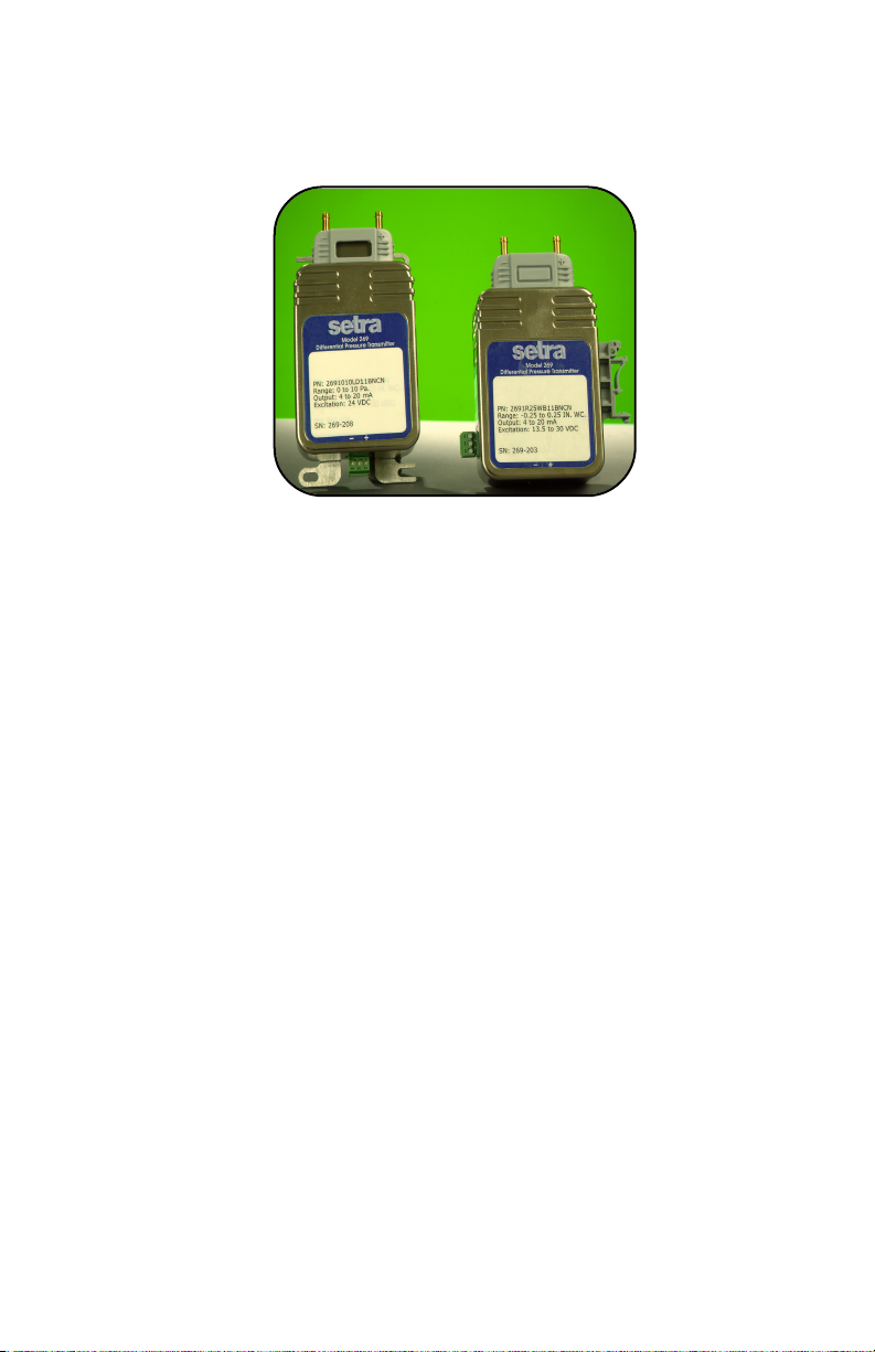
Setra Systems Model 269 High Performance
Very Low Differential Pressure Transducer
1.0 GENERAL INFORMATION
Every Model 269 has been tested and calibrated before shipment. Specific
performance specifications are shown on page 3 of this Guide.
Setra Systems 269 pressure transducers sense differential or gauge (static)
pressure and convert this pressure difference to a proportional high level
analog output for both unidirectional and bidirectional pressure ranges. A
current output of 4 to 20 mA is offered.
2.0 MECHANICAL INSTALLATION
2.1 Media Compatibility
Model 269 transducers are designed to be used with air or nonconducting
gases. Use with liquids or corrosive gases will damage the unit.
2.2 Environment
The operating temperature limits of the 269 are -20°F to +160°F
The compensated temperature range is 20°F to +140°F
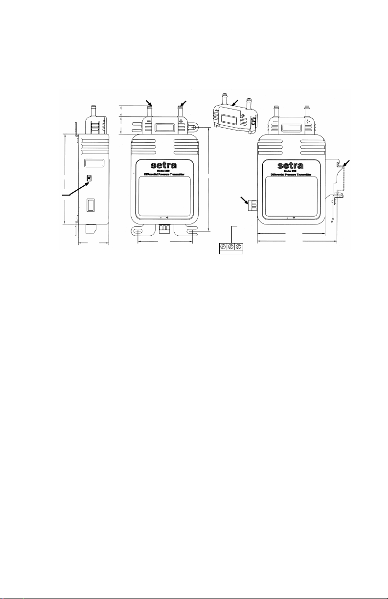
2.3 Pressure Fittings
The Model 269 is designed to be used with 3/16” I.D. push-on tubing on a
removable process head. Both the positive (high) pressure port and the
reference (low) pressure port are located on the top of the unit, labeled “+”
(HIGH) and “-” (LOW) respectively. For best results (shortest response times),
3/16” I.D. tubing is suggested for tubing lengths up to100 feet long, 1/4” I.D. for
tubing lengths up to 300 feet, and 3/8” I.D. for tubing lengths up to 900 feet
(See Diagram 1).
3.0 ELECTRICAL INSTALLATION
3.1 Current Output Units
The Model 269 is a two-wire loop-powered 4 to 20mA current output unit and
delivers rated current into any external load of 0 to 800 ohms. These terminals
have the designation of + and - (See Diagram 1).
Page 2
The current flows into the + terminal and returns back to the power supply
through the - terminal (See Diagram 2). The power supply must be a DC
voltage source with a voltage range between 13.5 and 30 measured between
the + and - terminals. The unit is calibrated at the factory with a 24 VDC loop
supply voltage and a 250 ohm load.
Low Pressure Port
.48”
High Pressure Port
Detachable Process
Head
Din
Rail
4.50”
Detachable
Electrical
Connector
Shield
to
Ground
- +
2.90”
3.70”
Turn-Down
Switch
3.90”
1.30”
2.35”
4.0. CALIBRATION
The 269 transducer is factory calibrated and should require no field adjustment
if mounted in a vertical position. Whenever possible, any zero and/or span
offsets should be corrected by software adjustment in the user’s control system.
However, fine zero and span adjustments can be made thru a calibration secure
access key. The Model 269 transducer zero offset is trimmed in the vertical
position (pressure ports pointing upward) prior to shipping from factory.
4.1 Zero/Span Adjustments with Security Key
To make secure zero and span adjustments, remove detachable process head by
pressing and pulling on side tabs. Install calibration security key in-place of
process head. (See Diagram 3).
4.2 Zero Adjustment (Current Output)
While applying zero differential pressure, zero may be adjusted by pressing the
cal button to tare zero. If fine adjustment is needed on analog output, depress
cal button while turning the encoder.
4.3 Span Adjustment (Current Output)
Span or full scale output adjustments should only be performed by using an
accurate pressure standard (electronic manometer, digital pressure gauge, etc.)
with at least comparable accuracy to the 269 transducer. With full range
pressure applied to the high pressure port (reference port open to atmosphere),
the span may be adjusted by pressing the cal button to set span. If fine
adjustment is needed on span, and control pressure is applied at least 75% of
full range, turn encoder until target output is achieved.
Diagram 1
4.4 Turn Down Adjustment (Option)
For units with optional turn-down gain, turn down is easily adjusted through
use of slider switch located on side of unit. (See Diagram 1)
2
Page 3

Current Circuit Diagram
269
13.5 to 30 VDC+_
Current
Monitoring
Device
Security Cal Key
Cal Button
Cal Encoder
Diagram 3
Diagram 2
4.5 Restoring Factory Calibration
To restore factory set calibration, turn unit off power and press cal button. Turn
on the power while cal button is depressed and release cal button.
5.0 MODEL 269 PERFORMANCE SPECIFICATIONS
Performance Codes V E G
Accuracy Class (FS) ±0.25% FS ± 0.50% FS ±1.0% FS
Non-Linearity
Terminal Point ±0.15% FS ± 0.35% FS ±0.75% FS
BFSL ±0.10% FS ± 0.25% FS ±0.55% FS
Hysteresis (Typical) ±0.05% FS ± 0.05% FS ±0.10% FS
Non-Repeatability ±0.05% FS ± 0.05% FS ±0.10% FS
Thermal Effects
Compensated Range °F 20 to +140
Zero Shift %FS/°F 0.01% 0.02% 0.03%
Span Shift %FS/°F 0.01% 0.02% 0.03%
Maximum Line Pressure 2 psi
Overpressure 2 psi in positive or negative direction
Long-term Stability 0.5% FS/1 Yr
Position Effect Range Zero Offset (%FS/G)
(Unit is factory calibrated at 0g effect To 0.1 in. WC 2.50
in the vertical position, pressure To 0.5 in. WC 1.00
ports pointing upward.) To 1.0 in. WC 0.50
To 2.5 in. WC 0.22
To 5 in. WC 0.14
Electrical
Calibrated at factory with a 24 VDC loop supply and a 250 ohm load.
Zero output factory set to 4±.04 mA for unidirectional pressure ranges and 12±.04 mA for
bidirectional ranges in vertical position.
Span factory set to 16±.04 mA.
3
Page 4

6.0 EMC CERTIFICATION
This product complies with EN61326 Electrical Equipment for Measurement, Control and Laboratory use - EMC
Requirements for Minimum Requirements and Industrial Locations. Special caution should be taken to meet
Standard EN61000-4.5: 1995 Surge Immunity if any of the following conditions apply to the installation: The
product is installed outside; all or any part of the cable is exposed to the outside; the cable is greater than 30
meters in length. In order to meet the Surge Immunity Requirements, the following conditions must be
followed during installation:
1. Shielded cable must be used, and the shield must be tied to earth ground (not power supply
ground) on at least one end of the cable shield/drain wire. The shield must be maintained all the
way from sensor to the power supply.
2. If unshielded cable is used, an earth grounded metal conduit fitting can be used to replace the
shielded cable.
3. For a sensor with a metal body or enclosure, the body/enclosure must be ground to earth. If a
protective metal housing is used, the metal housing should be grounded to earth.
4. If a protective plastic housing is used, the housing must be able to withstand at least 2 KV from
the housing to earth ground, without damaging the circuit.
7.0 RETURNING PRODUCTS FOR REPAIR
Please contact a Setra application engineer (800-257-3872, 978-263-1400) before returning unit for repair to
review information relative to your application. Many times only minor field adjustments may be necessary.
When returning a product to Setra, the material should be carefully packaged and shipped prepaid to:
To assure prompt handling, please supply the following information and include it inside the package or
returned material:
1. Name and phone number of person to contact.
2. Shipping and billing instructions.
3. Full description of the malfunction.
4. Identify any hazardous material used with product.
Notes: Please remove any pressure fittings and plumbing that you have installed and enclose any required
mating electrical connectors and wiring diagrams.
Setra Systems, Inc.
159 Swanson Road
Boxborough, MA 01719-1304
Attn: Repair Department
Allow approximately 3 weeks after receipt at Setra for the repair and return of the unit.
Non-warranty repairs will not be made without customer approval and a purchase order to cover repair
charges.
Setra maintains a complete calibration facility that is traceable to the National Institute of Standards &
Technology (NIST). If you would like to recalibrate or recertify your Setra pressure transducers or transmitters,
please call our Repair Department at 800-257-3872 (978-263-1400) for scheduling.
8.0 WARRANTY AND LIMITATION OF LIABILITY
SETRA warrants its Model 269 products to the original consumer purchaser against defects for a period of one
year from the date of sale by SETRA, as shown in its shipping documents. Without charge, SETRA will repair or
replace products found to have manufacturing defects within the warranty period.
The serial number or date code must not have been removed, defaced or otherwise changed.
SETRA must be notified in advance of any returns; any products returned to SETRA must be transportation
prepaid.
The foregoing warranty is in lieu of all warranties, express, implied or statutory, including but not limited to, any
implied warranty of merchantability for a particular purpose.
SETRA’s liability for breach of warranty is limited to repair or replacement, or if the goods cannot be repaired or
replaced, to a refund of the purchase price. SETRA’s liability for all other breaches is limited to a refund of the
purchase price. In no instance shall SETRA be liable for incidental or consequential damages arising from a
breach of warranty, or from the use or installation of its products.
No representative or person is authorized to give any warranty other than as set out above or to assume for
SETRA any other liability in connection with the sale of its products.
159 Swanson Road, Boxborough, MA 01719-1304
SS2135 Rev. D 7/19/07
Tel: 800-257-3872/978-263-1400
Calibration Services
ISO
9001:
2000
Certified
✓
4
 Loading...