

Page 1

Quick Start
Guide
Last change: 31.05.2016
Applies to software version 1.6.0 or higher
Page 2

Quick Start Guide
[Introduction] 4
1 Electronic Shelf Labeling – A brief introduction 4
2 What’s in your Smart Box? 5
3 The G1 label family 6
3.1 Key Features 7
4 Core appliance 8
4.1 Key Features 8
[Getting Started] 9
1 Get the latest software and documentation 9
2 Install software 9
2.1 System requirements 9
2.2 Installation process 9
2.3 imagotag Customer and Partner Portal 10
3 Core appliance initial setup 11
3.1 USB device configuration 11
3.2 Configuration file creator 12
3.3 Front side LEDdescription 13
3.4 Additional documentation 13
4 Start Core Service and Control Center 14
4.1 Starting imagotag Core Service 14
4.2 Starting imagotag Control Center 15
4.3 Activating your license 17
5 Access Point Configuration 19
5.1 Connect and configure AP-2010 19
5.2 Connect and configure MAP-2014 T/Q & LANCOM L-151e/322e 22
5.3 Selecting channels 27
6 Setup Security 28
6.1 General encryption features and how does it work 28
6.2 Set the encryption key 28
7 Register labels 29
7.1 General procedure 29
7.2 What's on the label? 29
Page 2 of 50
Page 3

Quick Start Guide
7.3 Handheld terminals, USB barcode scanner and iOS-App 31
7.4 Encryption status 32
7.5 Unlocking labels 33
8 Start tagging 35
8.1 What can I do now? 35
8.2 Sending pictures to labels 35
8.3 Article management 35
8.4 Matchings/Multi-Facing 36
8.5 Set (extended) filters for enums 38
8.5 Templates 39
9 Integration 44
9.1 Webservice integration 44
9.2 Plugins 44
9.3 Custom integration 44
[Troubleshooting] 45
1 FAQ 45
1.1 imagotag Core Service Dashboard 47
1.2 Running the imagotag Core Service as a background service 47
1.3 Where can I find the license file for my SmartBox? 48
1.4 Deleting the demo articles 48
1.5 Labels don’t come online 48
1.6 The encryption does not work 48
1.7 Unlocking labels 48
1.8 Starting Java applications 48
1.9 Encoding problems 50
1.10 Further documentation 50
Page 3 of 50
Page 4
Quick Start Guide
[Introduction]
1 Electronic Shelf Labeling – A brief introduction
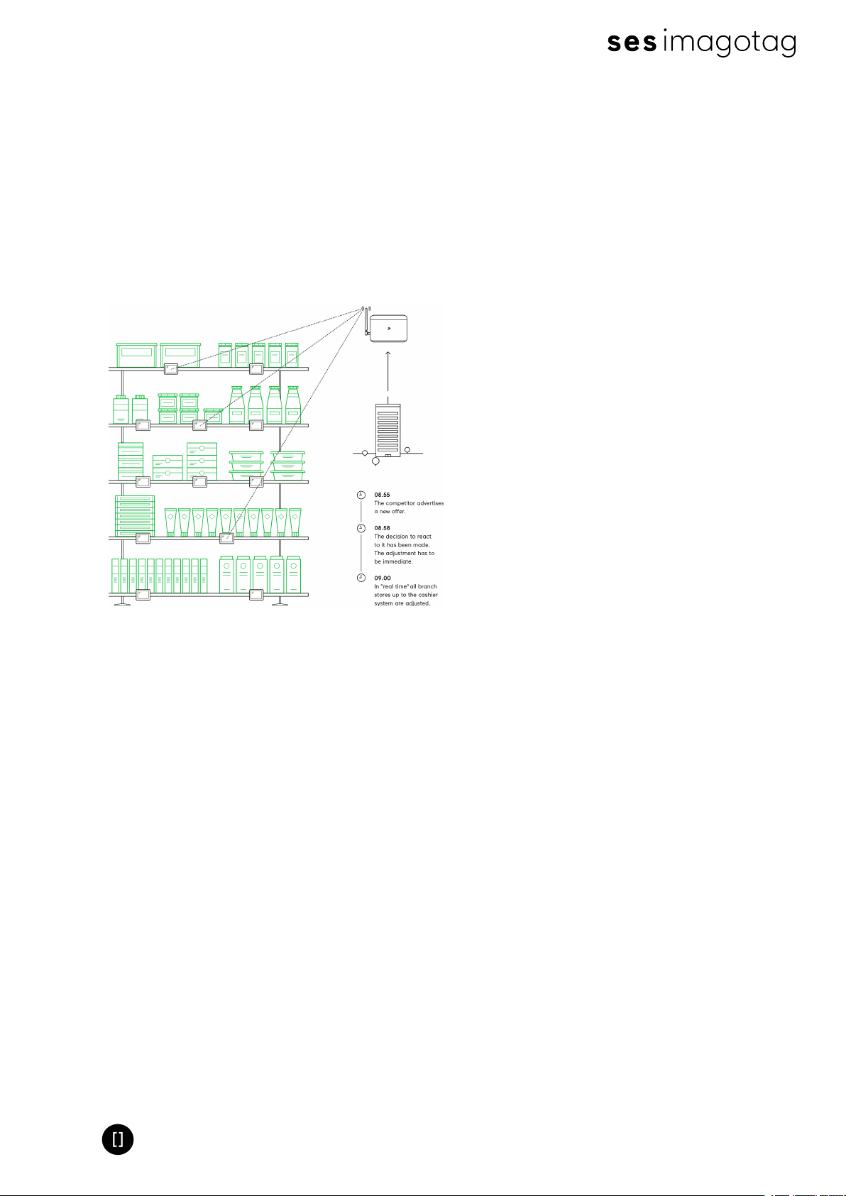
An electronic shelf label is a device that shows article data and price information on its
display. In comparison to printed labels the information is automatically updated if price or
article data changes.
l Cost reduction through elimination
of manual price changes
l Fully automatic price updates from
the headquarters to the branch
stores within seconds
l Process security and price integrity
– 100% correlation between cash
point and shelf
l Increased flexibility in price design
and immediate reaction to market
situation Image gain due to use of
highly modern technology
l Simplified processes for store per-
sonnel
FIGURE 1-1: Electronic Shelf Labeling
l Enhanced sales & price profitability
maximize price performance and
profit opportunities
Page 4 of 50
Page 5
Quick Start Guide
2 What’s in your Smart Box?
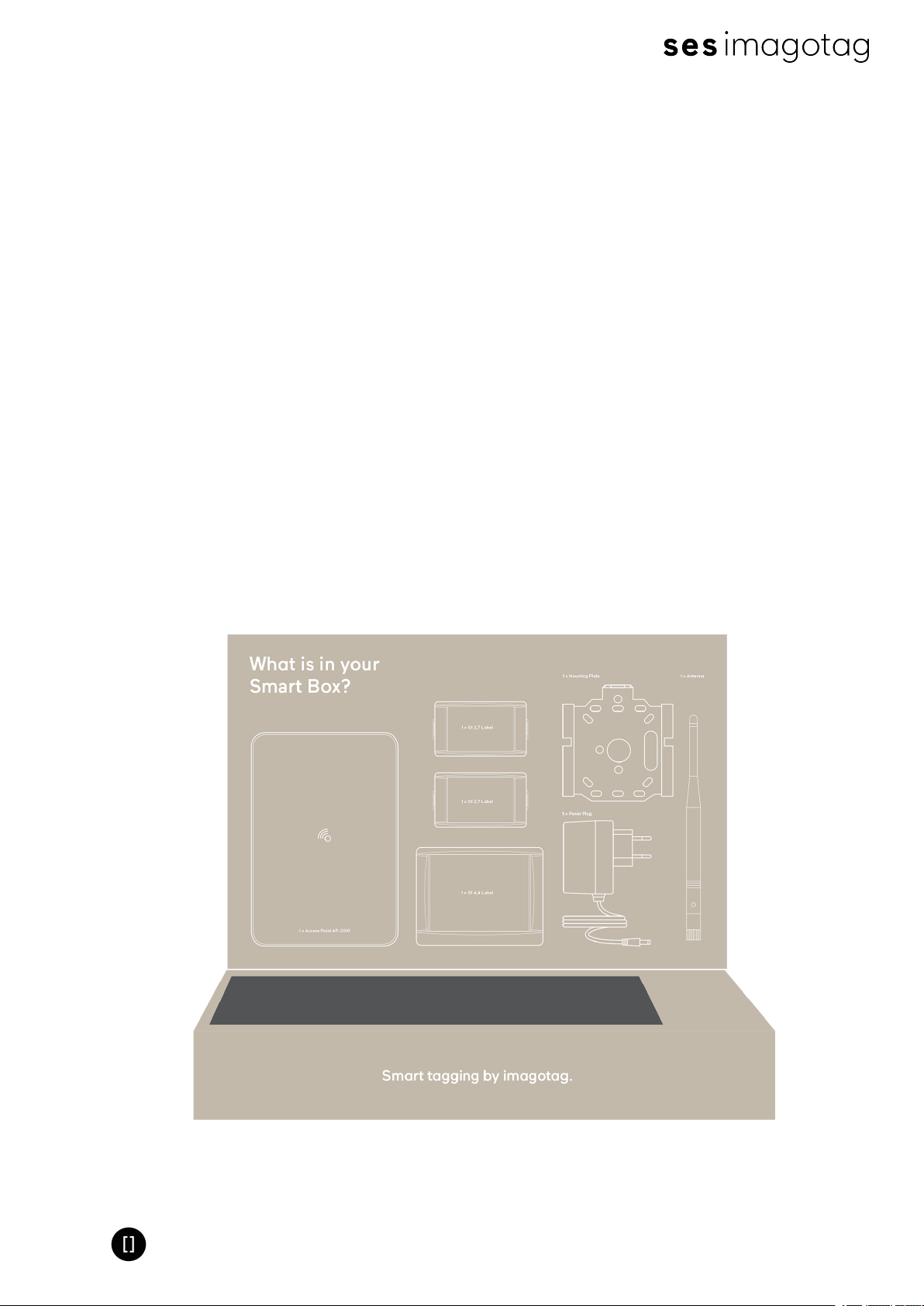
l 2x G1 2.7 Labels / 1x G1 4.4 Label
o
The G1 electronic shelf label family offers high-quality display options, operating
with a replaceable battery and thus working with any external power supply.
Thanks to the perfect readability of the e-Ink displays and our outstanding wireless
data transmission technology you can implement all your sales, marketing, and
logistic strategies.
l 1x Access Point AP-2010 incl. Antenna
o
The AP-2010 by imagotag is the communication center in the store that transmits
price information to the labels. Up to 10 000 labels can be managed per access
point and the self-organizing network allows automatic roaming of labels without
manual handling. It supports 11 selectable ESLchannels.
l 1x Mounting Plate
o
Metal Mounting Plate for Mounting the AP-2010 on Walls, Ceilings or other Mounting-Rails.
l 2x Caddy Clips
o
With our system you’re able to mount your labels almost wherever you want.
l 1x Power Plug
o
Power Plug to supply power for the AP-2010 (Power over Ethernet is also available).
Page 5 of 50
Page 6
Quick Start Guide
3 The G1 label family
The imago G1 electronic shelf label family offers high-quality display options, operating with a
replaceable battery and thus working without any external power supply. The G1 red family is
capable of changing all pixels to black, white or red.
The current line-up has display sizes from 1.6 inch to 7.4 inch. They may be used in landscape
and portrait mode and can be customized with changeable front covers.
The performance of the labels (updates per hour) depends on the mode of the access point. In
the USA and Canada the AP-2010 usa/canada bundle incl. antenna with limited data efficiency
is required (based on the FCC/ICregulation).
Caption
G1 retail 1.6 red NFC 152 x 152 140 b/w/r 4* 27.5 x 27.5 7500/4600 1
G1 retail 2.2 red NFC / Boss-
ard 2.2 red NFC
G1 retail 2.6 red NFC 296 x 152 125 b/w/r 4* 60.1 x 30.7 4500/2600 2
G1 retail 2.7 264 x 176 117 b/w 8* 57.3 x 38.2 5000/2700 4
G1 retail 2.7 red NFC 264 x 176 117 b/w/r 4* 57.3 x 38.2 4500 2
G1 retail 4.2 400 x 300 120 b/w 4* 84.8 x 63.6 3000 4
G1 retail 4.2 red NFC 400 x 300 120 b/w/r 4* 84.8 x 63.6 2000/1300 2
G1 retail 4.4 400 x 300 113 b/w 4* 90 x 67 3000/1600 4
G1 retail 4.4 red NFC 400 x 300 113 b/w/r 4* 90 x 67 2000 2
G1 retail 4.5 480 x 176 117 b/w 4* 104.2 x 38.2 4300 4
G1 retail 4.5 red NFC 400 x 300 113 b/w/r 4* 90 x 67 2500 2
G1 retail 7.4 800 x 480 126 b/w 12* 97 x 161.6 1000/500 8
G1 retail 7.4 red NFC 800 x 480 126 b/w/r 4* 97 x 161.6 600/300 2
S-tag 6 HFNFC - - b/w 4 53 x 19.3 20000/20000 4
Display Res-
olution
212 x 104 111 b/w/r 4* 48.6 x 23.8 8500/5000 2
Density
(dpi)
Display
Colors
Useable
Pages
Active Dis-
play Area
(mm)
Updates/hour/AP
(standard /
FCC&IC mode)
Battery
lifetime: 5
years with
N updates
per day
*One useable page is shared with the registration code page. This page is initially shown when
the label is shipped. After registration this page can be used as a custom page. To restore the
original content a service utility is required. To prevent accidentials overwrite this page is
protected. To unlock this page contact the imagotag support.
The content of all pages except page number 0 won't remain after a firmware update.
Page 6 of 50
Page 7

Quick Start Guide
3.1 Key Features
l 2.4 GHz bi-directional MSK proprietary radio
l Radio coverage: up to 25 meters
l Return Signal: yes
l 11 available communication channels
l Ultra-low power consumption
l Customer-replaceable battery
l Full graphical e-Ink display with paper-like readability
l Changeable and customizable front covers
l Super wide viewing angle (nearly 180 degrees)
l Flexible mounting options available
l May be used in landscape and portrait mode
l Fast response time (less than 15 seconds)
l Water resistant
l 128-bit AES encryption with secure key exchange
l Multiple pages support with preloading and fast page switching
l Integrated NFCtag as an option
Page 7 of 50
Page 8
Quick Start Guide
4 Core appliance
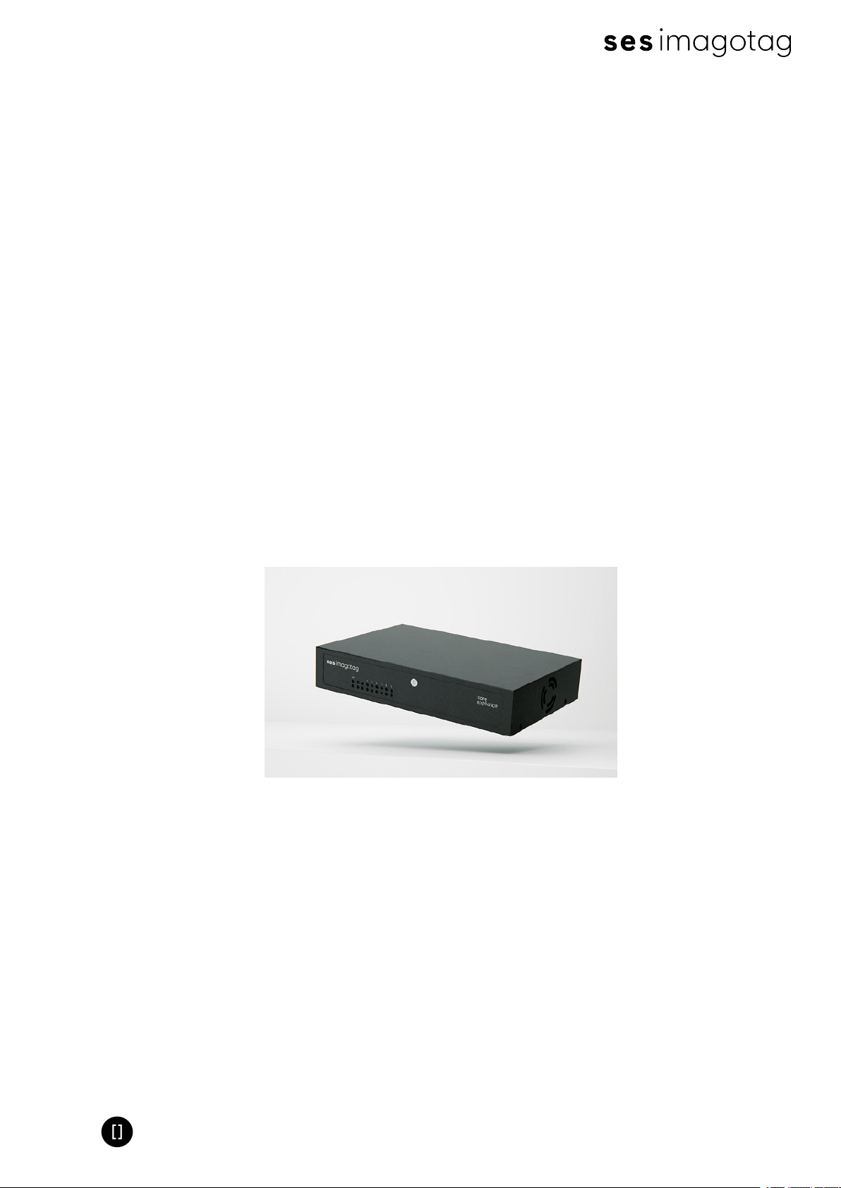
The core appliance/core appliance mini is a compact network hardware which can be used to
run the imagotag Core Service in the store, instead of using an additional dedicated server. The
imagotag Core Service is always needed in the store locally, also when cloud-based/centralized
middleware systems like Jeggy S or Bison ESL Suite is used.
4.1 Key Features
l core appliance is optimized to run up to 30 000 labels and 7 access points
l core appliance mini is optimized to run up to 500 labels and 3 access points
l Easier and faster shop installations (“Plug and Play”)
l Is not recognized as an additional server
l Low maintenance
l Easy replace/restore when hardware crashes
l Limited deployment variabilities
l Lower development costs
l Lower support costs
l Better brand recognition
l Easier to sell as a “solution in a box”
l Less overall risk for system integrators
Page 8 of 50
Page 9

Quick Start Guide
[Getting Started]
1 Get the latest software and documentation
Register at the imagotag Customer and Partner Portal to get access to the latest software
suite and documentation.
https://portal.imagotag.com
After registration your access is limited. Contact the imagotag Support Team
([email protected])to get further access and information.
2 Install software
There’s several software you’ll have to install in order to configure and setup your ESL system.
You’ll just have to extract the following 3 archives in a location of your choice:
1. imagotag Core Service (previously known as imagotag ESL Server) <server.zip>
2. imagotag Control Center (previously known as imagotag ESL Client)<client.zip>
3. Template Editor <template.zip>
2.1 System requirements
l Server hardware: Pentium 4 (2 GHz or higher), 2 GB RAM
l Java Runtime Environment Version 6, Update 36 or higher
l Windows XP, Windows 7, Windows Server 2008 (R2), Windows 10, Suse Enterprise Linux
11, Ubuntu 12 (all 32/64-bit versions), Mac OS X
l imagotag Core Software Suite
l imagotag AP-2010
l imagotag Labels
l License key
2.2 Installation process
Please unpack the zip-archives <server.zip>, <client.zip> and <template.zip> on your machine e.g. under C:\imagotag\.
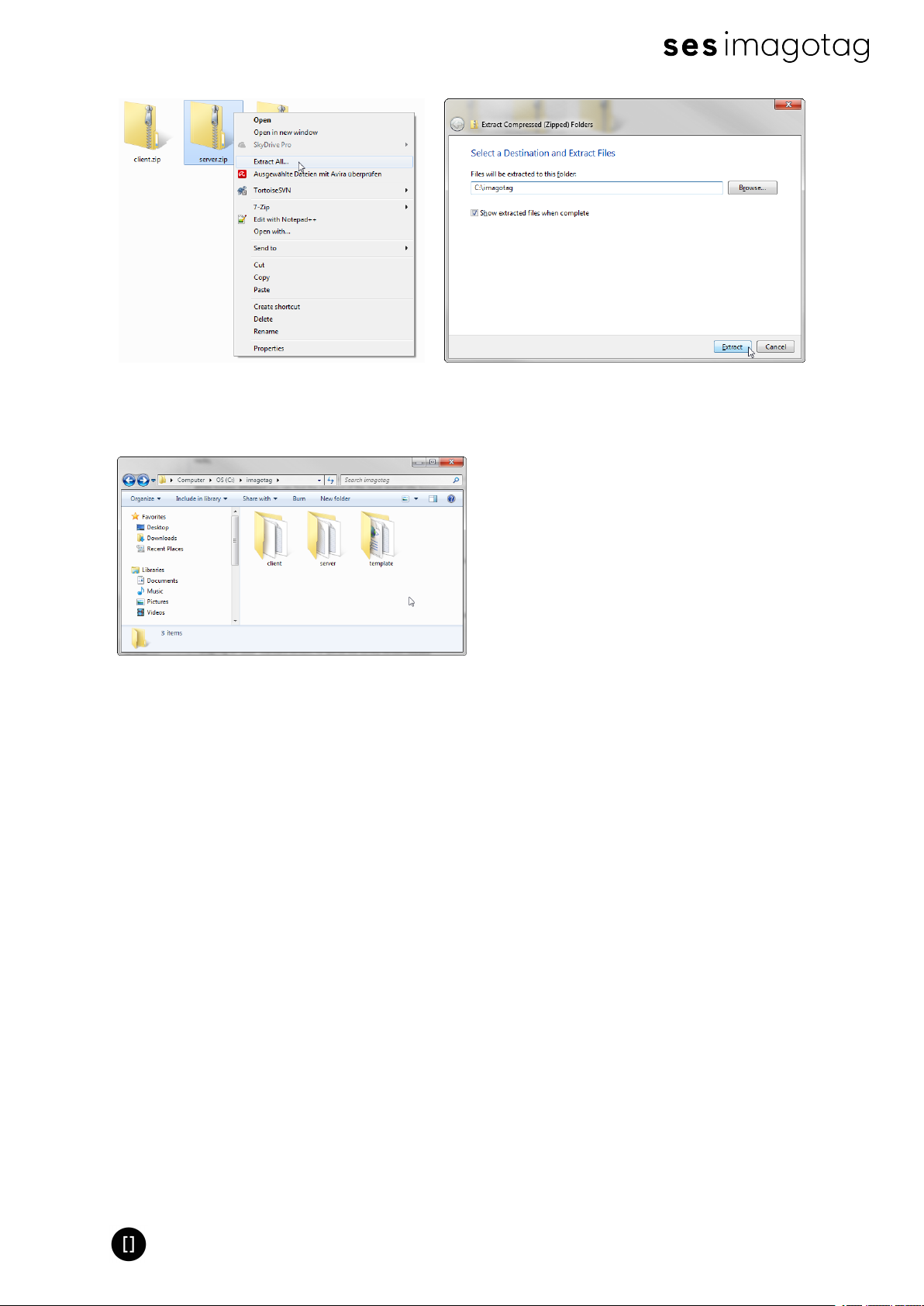
Note: To unpack the zip-files you can either use the windows internal archive-unpacker (see
screenshots) or an unpack tool of your choice (e.g. the free tool 7zip – www.7zip.org).
Page 9 of 50
Page 10
Quick Start Guide
FIGURE 1-2: Unpack/Install imagotag Software #1 FIGURE 1-3: Unpack/Install imagotag Software #2
After unpacking all 3 archives, your folder should look something like this:
FIGURE 1-4: Unpacked imagotag software folder
The imagotag software is now installed and you can step forward to point Start Core Service and
Control Center - Start Core Service and Control Center.
2.3 imagotag Customer and Partner Portal
After user registration and activation you will have access to documentation and you can
activate, manage and download your imagotag software licenses see Activating your license on
page 17. Your user account will not be assigned to a customer account yet. If assigned, you
have access to all shipments here including lists of label IDs, registration codes and unlock
codes. To get access there must be a completed order and your account needs to be verified
(existing customer account required).
Page 10 of 50
Page 11
Quick Start Guide
3 Core appliance initial setup
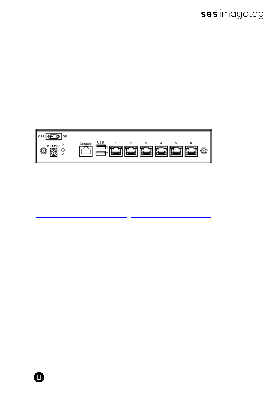
To operate the appliance there are only a few steps necessary:
1. Supply with power
2. Turn it on (button on the backside of the device)
3. Plug it into your network
Per default, the imagotag core appliance comes with DHCPenabled. So if you have a
DHCPservice running you can find it with the MAC address which is printed on the bottom side
of the appliance.
If there's no way to get access to the DHCPserver we recommend to use a USBdevice with a
configuration file to configure the appliance initially.
FIGURE 1-5: Core appliance rear view
3.1 USB device configuration
You can find an example configuration file (example.config) at our customer portal.
Core appliance service reference mode | Core appliance example.config file
After downloading, editing and copying the configuration file onto any USBdevice, the
configuration is automatically adopted after plugging in the USB flash drive into the appliance.
A triple beep indicates the successful configuration. A single beep signals that the
configuration hasn't been set successful.
The web UIinterface of the appliance is now available under http://<ip-address>.
The initial configuration of the appliance can be compared with the installation and start of an
imagotag Core Service. After configuration, you can access the appliance via the imagotag
Control Center from every system connected to your network (see Starting imagotag Control
Center on page 15).
Page 11 of 50
Page 12

Quick Start Guide
3.1.1 Example.config file
To set up your appliance for the first run you'll have to set at least the following network
parameters:
l IPaddress
l Subnet mask
l Optional: Gateway, DNS
To set the parameters mentioned above the contents of the configuration file might look like
this:
# Set IP address of bridge interface
set network br0 192.168.1.100 255.255.255.0
# Set a gateway
set gateway 192.168.1.1
# Set a nameserver
set dns 192.168.1.21
Note:This simple bridge configuration connects the network interfaces. No matter where the
network cable is plugged in, the appliance is accessible via the configured bridge address.
3.2 Configuration file creator
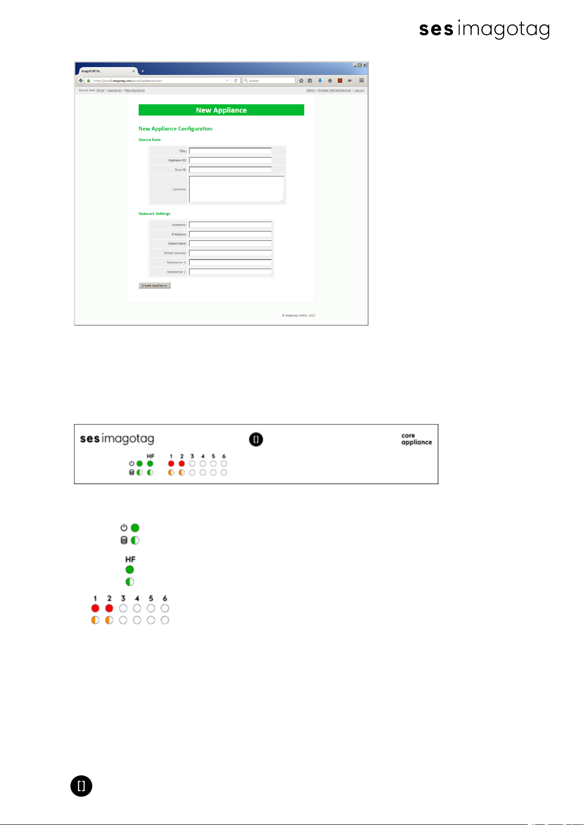
You'll also find a appliance configuration file creator wizard at our imagotag Customer and
Partner Portal. The wizard will help to create the correct configuration file which is used to set
the following configuration parameters:
Mandatory:
l Appliance ID
l IPaddress
l Subnet mask
Optional:
l Title
l Store ID
l Comment
l Hostname
l Default Gateway
l Nameserver 1
l Nameserver 2
Page 12 of 50
Page 13
Quick Start Guide
FIGURE 1-6: Appliance configuration file creator
3.3 Front side LEDdescription
On the front side of the appliance you can see several status information:
FIGURE 1-7: Core appliance front view LEDstatus information
Power on
Core Appliance is active
Core service running
Task executed
Port in use
Port/Device is active
3.4 Additional documentation
You can find additional documentation regarding the imagotag core appliance (e.g. a complete
service mode reference) on our imagotag Customer and Partner Portal
Page 13 of 50
Page 14
Quick Start Guide
4 Start Core Service and Control Center
4.1 Starting imagotag Core Service
If you've recently configured your imagotag core appliance the ESLService is already running
and you can step forward to the next step 15
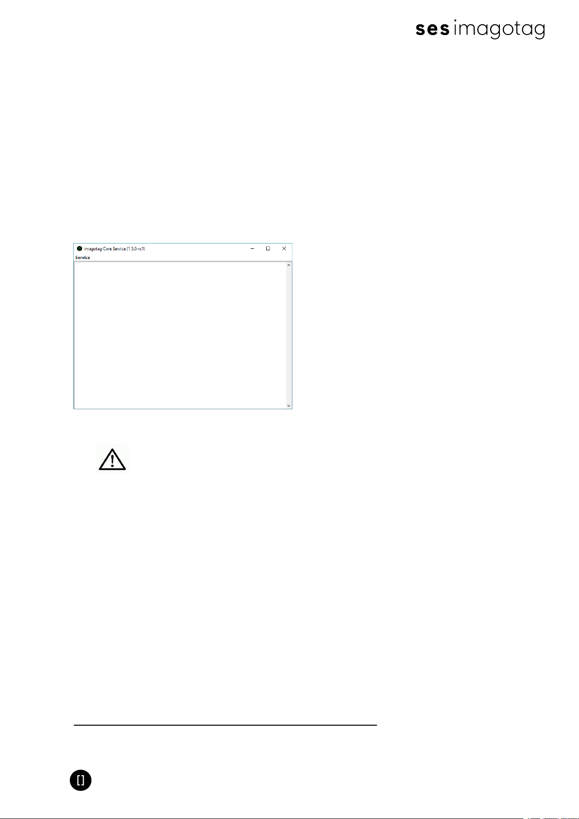
In order to start the ESL Service with the default configuration, just execute the jar file
“server.jar” as described in [Troubleshooting] and wait for the small service GUI to show up (if
the window doesn’t show up after all, make sure your Java installation and configuration is
correct).
FIGURE 1-8: Core Service web UI
The service will listen to TCP connections on Port 8000 and 8001 and UDP
connections on Port 8000. Please make sure that there is no firewall issue
and/or interference with other systems.
After start of the service you can check the web-GUI of the server:
URL: http://<host|ip>:8000
Login: admin/admin
During the first start the imagotag Core Service will automatically create a Derby1database. If
another database connection is needed or preferred, the connection parameters should be
validated by imagotag.
Note: As you can see there are several level numbers, by default the server instance will start
in level 3. You can find the description of the different levels in the Developer Reference (which
is also part of the documentation available at the imagotag Customer and Partner Portal) under
“Integration Levels”.
1
Apache Derby, an Apache DB subproject, is an open source relational database implemented
entirely in Java
Page 14 of 50
Page 15
Quick Start Guide
4.1.1 Example articles
For easier usage some example articles can be preloaded at the time you start the imagotag
Core Service. You can find the corresponding XMLarticle data here:
C:\imagotag\server\data\fixtures\.
To enable and disable the preloading of these fixtures go to the system configuration and set
the corresponding property "importFixtures"true or false.
Note: The article records are based on the XML-standard.
4.2 Starting imagotag Control Center
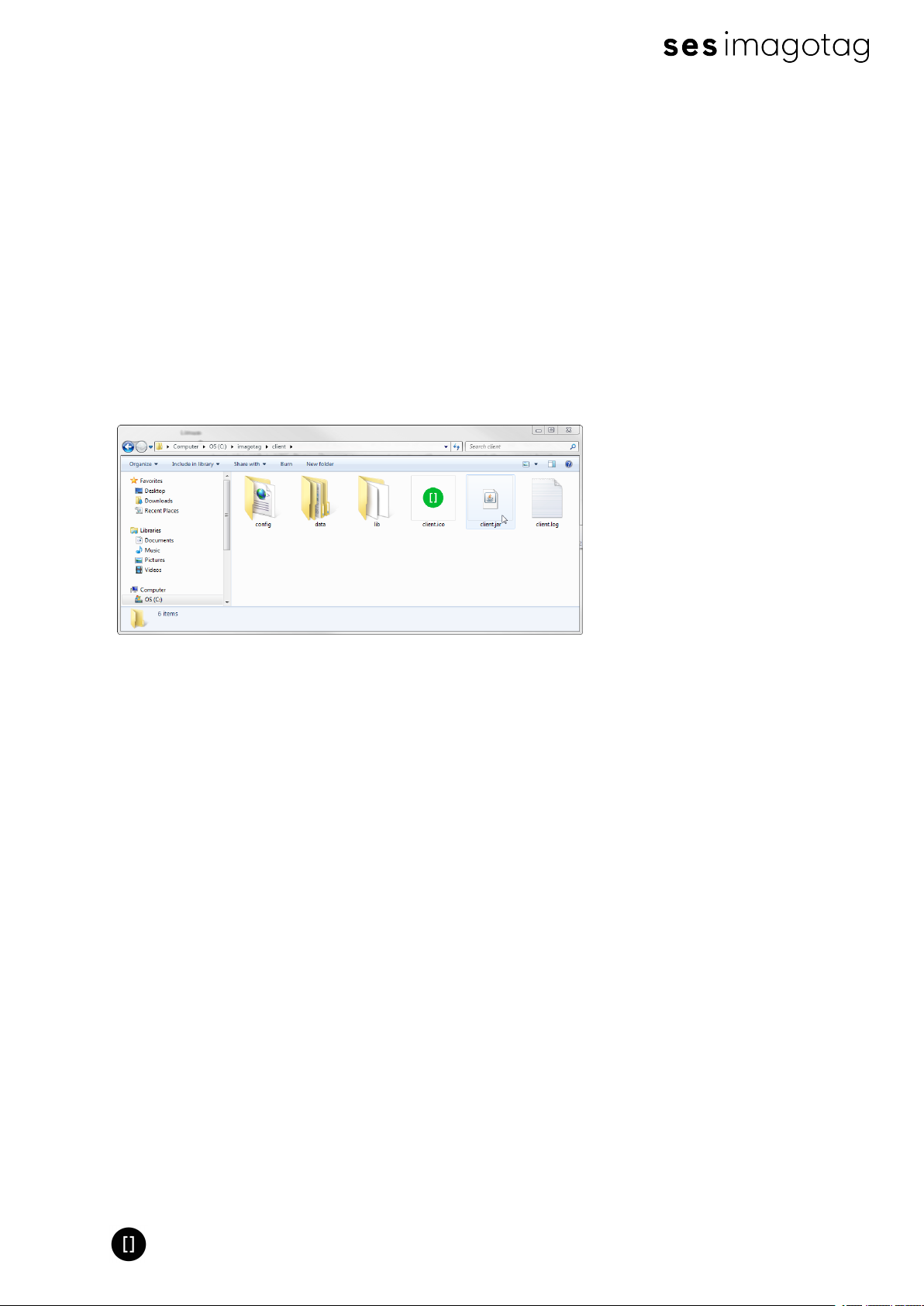
Go to the extracted client directory and execute the “client.jar” file.
FIGURE 1-9: Starting ESL Client
The client is configured to connect to a server on the local machine per default. In order to
change this to a remote machine in a network you have to start the client with an additional
parameter:
Windows
l Create a shortcut/Edit existing short cut
l Append “ --host hostnameOrIPAddress” at the end of the “Target” field. (Note: The text to
append starts with an space and there are 2 hyphens to add!)
Linux
l Append “ --host hostnameOrIPAddress” at the end of command (e.g. “java -jar client.jar --
host 192.168.1.100” Note: The text to append starts with an space and there are 2
hyphens to add!)
Page 15 of 50
Page 16
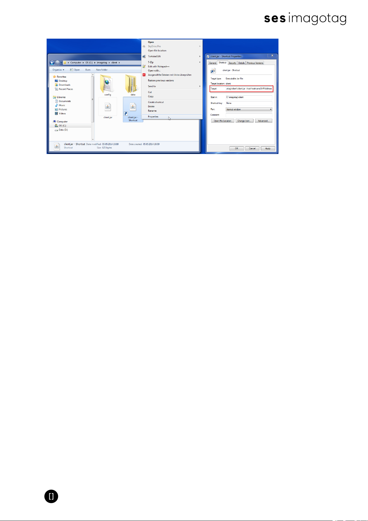
Quick Start Guide
FIGURE 1-10: Starting ESL Client with parameter
Page 16 of 50
Page 17
Quick Start Guide
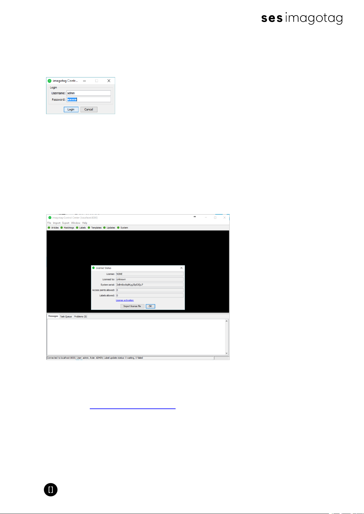
4.2.1 imagotag Control Center Login
l Username: admin
l Password: admin
FIGURE 1-11: imagotag Control Center Login
4.3 Activating your license
After starting the imagotag Core Service and imagotag Control Center it's necessary to activate
the license key which is included in the "Software License Document". To view your current
license status there's a License status dialog. You can find it in the imagotag Control Center
under "Help - License status". Since no license is activated/imported yet the window should
look similar to this:
FIGURE 1-12: License Status Dialog
Copy the "System serial" to the clipboard (STRG+Cor right click "Copy to clipboard")and then
click the "License activation". You'll be automatically redirected to the imagotag Customer and
Partner Portal https://portal.imagotag.com.
Please log in (or register a new user). After log in, you can see a summary of already activated
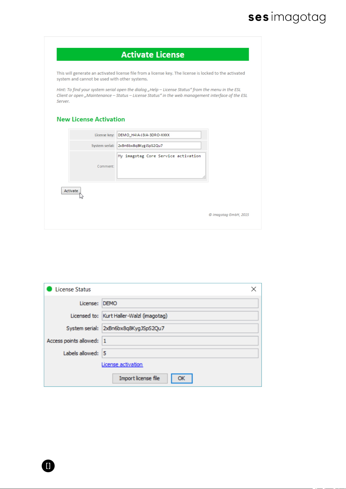
licenses and / or activate a new license. Click "activate new license".
Fill in "License key", copy/paste the "System serial"(from the "License Status"dialog), add a
Comment (optional) and click the "Activate"button.
Page 17 of 50
Page 18
Quick Start Guide
FIGURE 1-13: Activate License (imagotag Customer and Partner Portal)
Download the generated license file and complete the licensing process by importing the
license file to your ESLsystem. With the successful activation of your SmartBox demo license
you're now able to register and use up to five labels and one access point.
FIGURE 1-14: Import of license file downloaded before
Note: Press "F5"(after 15 seconds) to update the license status after license file import.
Page 18 of 50
Page 19

Quick Start Guide
5 Access Point Configuration
The access points AP-2010, MAP-2014 T/Q and LANCOM L-131e/L-322e are the communication
center in the store that transmits information to the labels. In order to ensure the
communication between imagotag Core Service, access point(s) and the labels the access
points have to be configured at the start of the imagotag Core Service.
5.1 Connect and configure AP-2010
5.1.1 Connect and configure
Before labels are able to communication with the server at least one access point needs to be
configured. In standard configuration the AP-2010 should get an IP-address via DHCP
(recommended) and is accessible via imagotag AP-2010 web UI:
URL: http://<host|ip>:8080
Login: admin/admin
Important Note: In this part of the Quick Start Guide it is assumed that a DHCP server is
present (you can find the steps to discover the access point without DHCP in the
Troubleshooting section - see [Troubleshooting] on page 45
5.1.2 Discover the Access Point
Before you can configure the access point it’s necessary that the server will discover it.
The following points have to be observed:
l Connect your machine to the same network as the AP
l Plug in the power supply of the access point
l During the boot process of the access point, start the imagotag Core Service software on
the computer
l When the access point is up (LEDturns orange), the server will discovery it with an IP
address (Note: The discovering process may take up to 2 minutes)
l Use the imagotag Control Center to connect to your imagotag Core Service
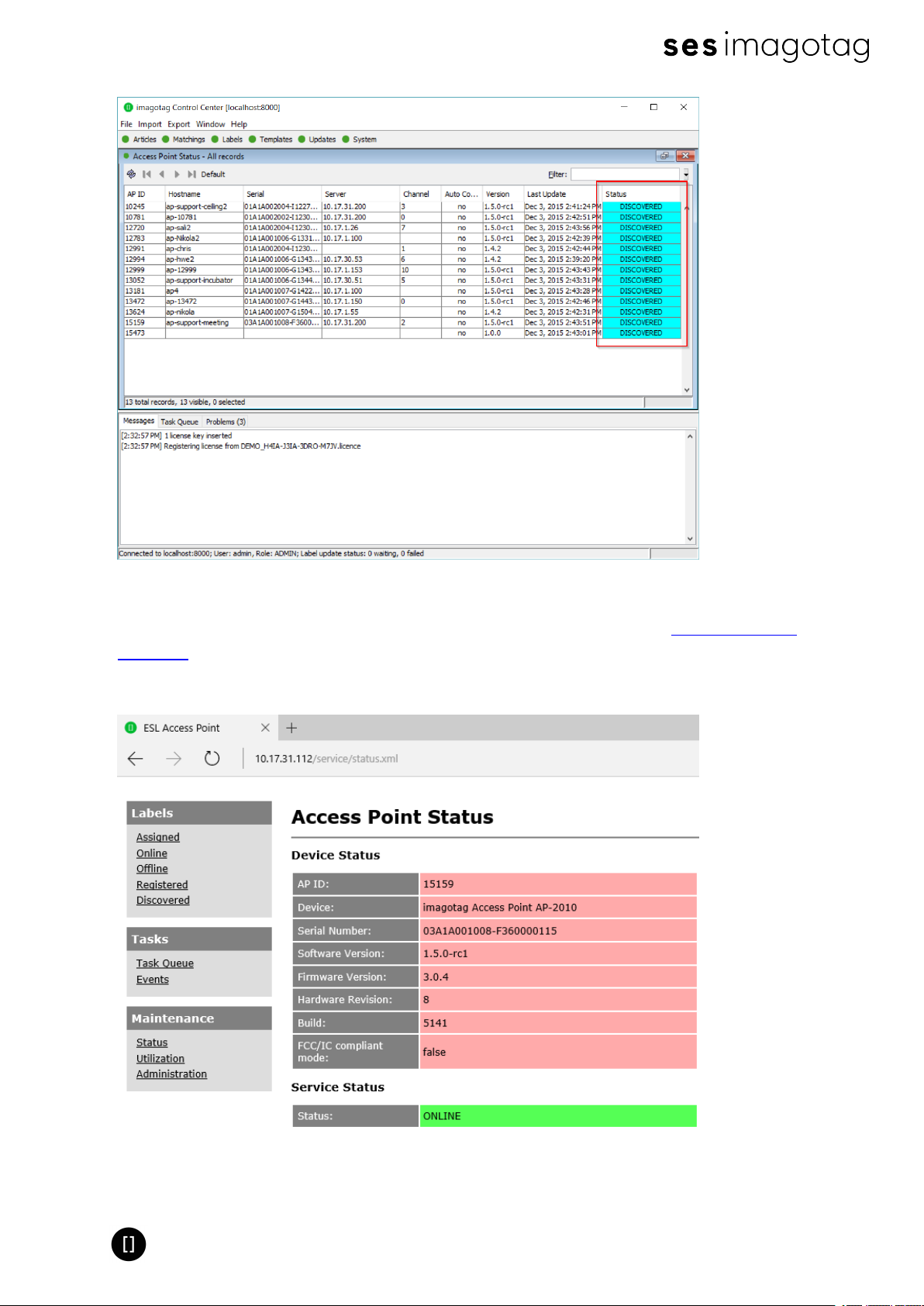
l Under System – Access Point Status – the AP should be listed as discovered (after suc-
cessful boot sequence)
Page 19 of 50
Page 20
Quick Start Guide
FIGURE 1-15: List of discovered Access Points
Now you’re able to configure the access point via AP-2010 web UI under http://<DHCP-IP-
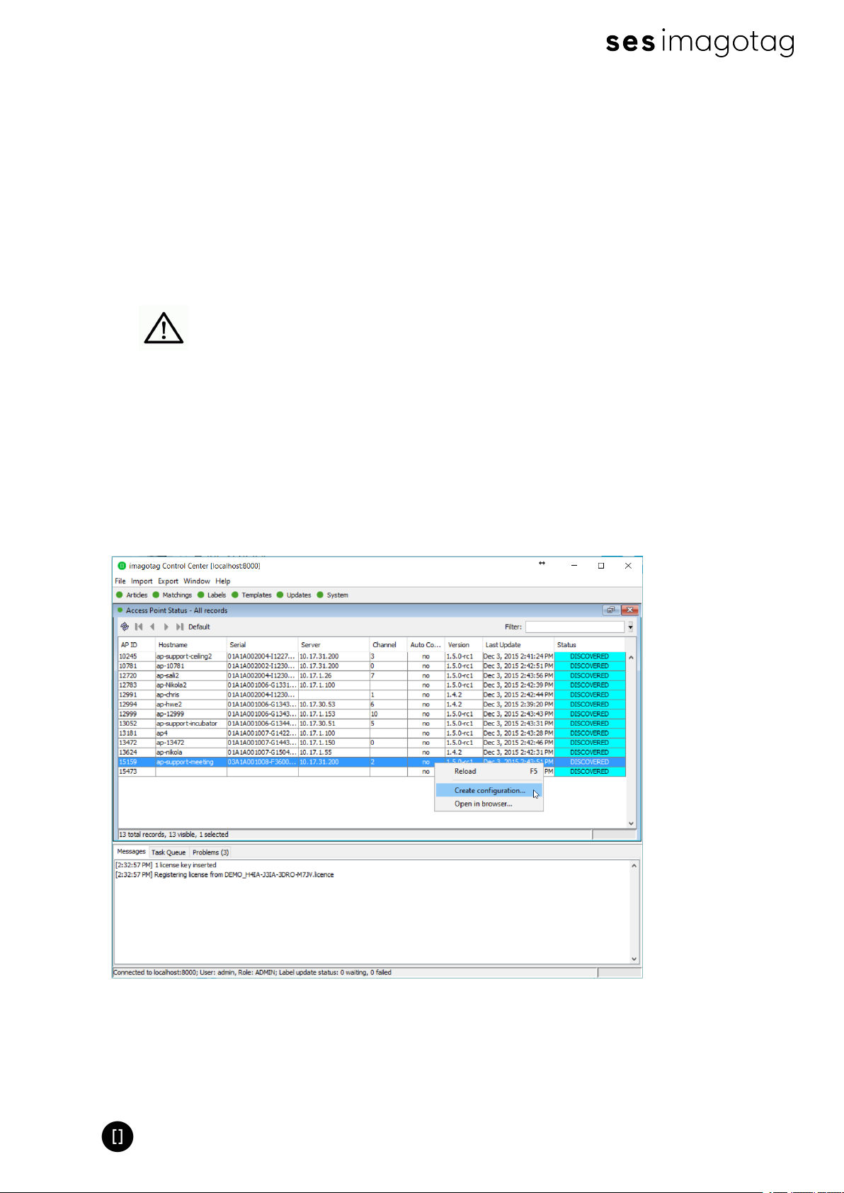
address> or a right click on the discovered AP –> Open in browser...
In the status overview you get some details about the AP-2010:
FIGURE 1-16: AP-2010 Status overview
Page 20 of 50
Page 21
Quick Start Guide
It’s recommended for the demo installation not to use the “Auto-Config” feature and configure
the AP manually.
5.1.3 Necessary configuration over the AP-2010 web UI
The following actions need to be performed over the web-GUI
1. Deactivate Centralized Configuration: Administration -> Configuration Mode
2. Set up network details (or leave DHCP): Administration -> Network
3. Set up an ESLchannel: Administration -> Wireless Channel
The AP-2010 supports 11 ESL channels. It’s recommended to choose one of
the recommended channels: 3, 5, 8, 9 or 10. These channels do not interfere
with standard Wi-Fi channels 1, 6, 11 and are scanned by the labels more often.
For further information about selecting channels see point Connect and
configure AP-2010.
5.1.4 Necessary configuration at the imagotag Control Center
After the configuration in the AP-2010 web UI it’s necessary to add this AP via the imagotag
Control Center: System – Access Point Configuration – New … or right click on a discovered
AP- Create configuration.
FIGURE 1-17: ESL Client AP configuration - System -> Access Pont Status -> Create configuration
Choose “Manual Configuration” if you don’t use Auto-Config and enter Access Point ID (AP ID)
and IP address (Host).
Page 21 of 50
Page 22
Quick Start Guide
Note: After the basic configuration in the AP-2010 web UI, it is also possible to fill in AP-ID and
AP-IP-Address automatically. For this choose "Create Configuration..." under System – Access
Point Status - Right click on the discovered and configured Access Point.
After saving the AP configuration you should see the AP under System – Access Point Status
as ONLINE. In addition the AP status LED should turn BLUE.
Note: It is possible to configure the access point via hostname. To get this working there has
to be a corresponding entry in the DNS.
5.1.5 The Status LED
There are several LED colors that indicates the main status of the access point.
Color Description Note
Red Boot process
Blue Normal mode ---
Operational, but not
Yellow
Red (blinking) Running Firmware Update
connected to any server
or no channel selected
Can take about 2 minutes, if it takes much
longer, the device is defective and there is a
need for service.
---
During this time there is no connection to the
electronic label
If there are any problems regarding the access point please see chapter [Troubleshooting].
5.2 Connect and configure MAP-2014 T/Q & LANCOM L-151e/322e
The LANCOM Access Point with Wireless-ePaper is the communication center in the store that
transmits price information to the labels. In order to ensure the communication between ESL
server, access point and the labels the LANCOM Access Point with Wireless-ePaper has to be
connected after the start of the ESL Server.
One way to configure the access point is on the client.
5.2.1 First configuration steps
As described in the Installation Guide (printed version included in the package) you’ll have to
configure the basic settings before setting up Wireless-ePaper using the imagotag imagotag
Core Service.
1. Installing the software or configuration using a web browser and setup wizards
2. Deploying and connecting the device
3. Searching for and configuring the device
After setting up the basic settings the following points have to be fulfilled:
Page 22 of 50
Page 23
Quick Start Guide
l Knowing the IP address of the AP-2010
l WLAN activated
Important Note: AP-2010 and the computer on which the imagotag Core Service runs should be
connected via Ethernet and not via WiFi, as this will result to regular failures.
5.2.2 Access Point IP
Before labels are able to communication with the server at least one access point needs to be
configured. After setting up the basics you should know the IP address of your AP-2010:
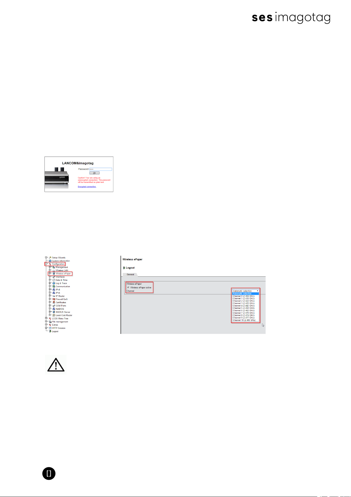
URL: http://<LANCOM/MAP-IP-address>
Login with the password set before.
FIGURE 1-18: Figure - LANCOM Web GUI Login
5.2.3 Configuration: Wireless ePaper
Under “Configuration – Wireless ePaper” you can check whether the module is activated or not.
You can also select a channel or leave the “Automatic selection” (recommended).
FIGURE 1-19: Figure - Configuration - Wireless ePaper
The AP-2010 supports 11 wireless channels. It’s recommended choose one of
the recommended channels: 3, 5, 8, 9 or 10. These channels are scanned by
the labels more often.
5.2.4 LCOS Menu Tree
Here you’ll find the necessary information for the imagotag Core Service Access Point
Configuration settings.
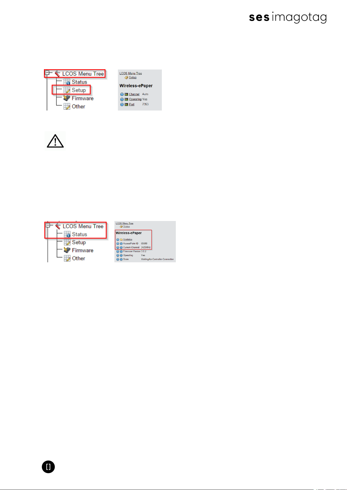
5.2.5 Setup – Wireless ePaper
Navigation: “LCOS Menu Tree – Setup – Wireless ePaper”
Page 23 of 50
Page 24
Quick Start Guide
It’s possible to change the ESL channels and do activate or deactivate the Wireless ePaper
system. Here you can also find the selected UDP port for the communication (port 7353 per
default).
FIGURE 1-20: Figure - LCOS Menu Tree - Setup - Wireless ePaper
The service will listen to TCP connections on Port 8000, 8001 and 8080 and
also UDP connections on Port 8000 and the port set in LCOS Menu Tree
(default 7353). Please make sure that there is no firewall issue and/or
interference with other systems.
5.2.6 Status – Wireless ePaper
Navigation: “LCOS Menu Tree – Status – Wireless ePaper”
After configuration you can see a summary of your Wireless ePaper settings under
FIGURE 1-21: Figure - LCOS Menu Tree - Setup - Wireless ePaper
5.2.7 Necessary configuration at the imagotag Control Center
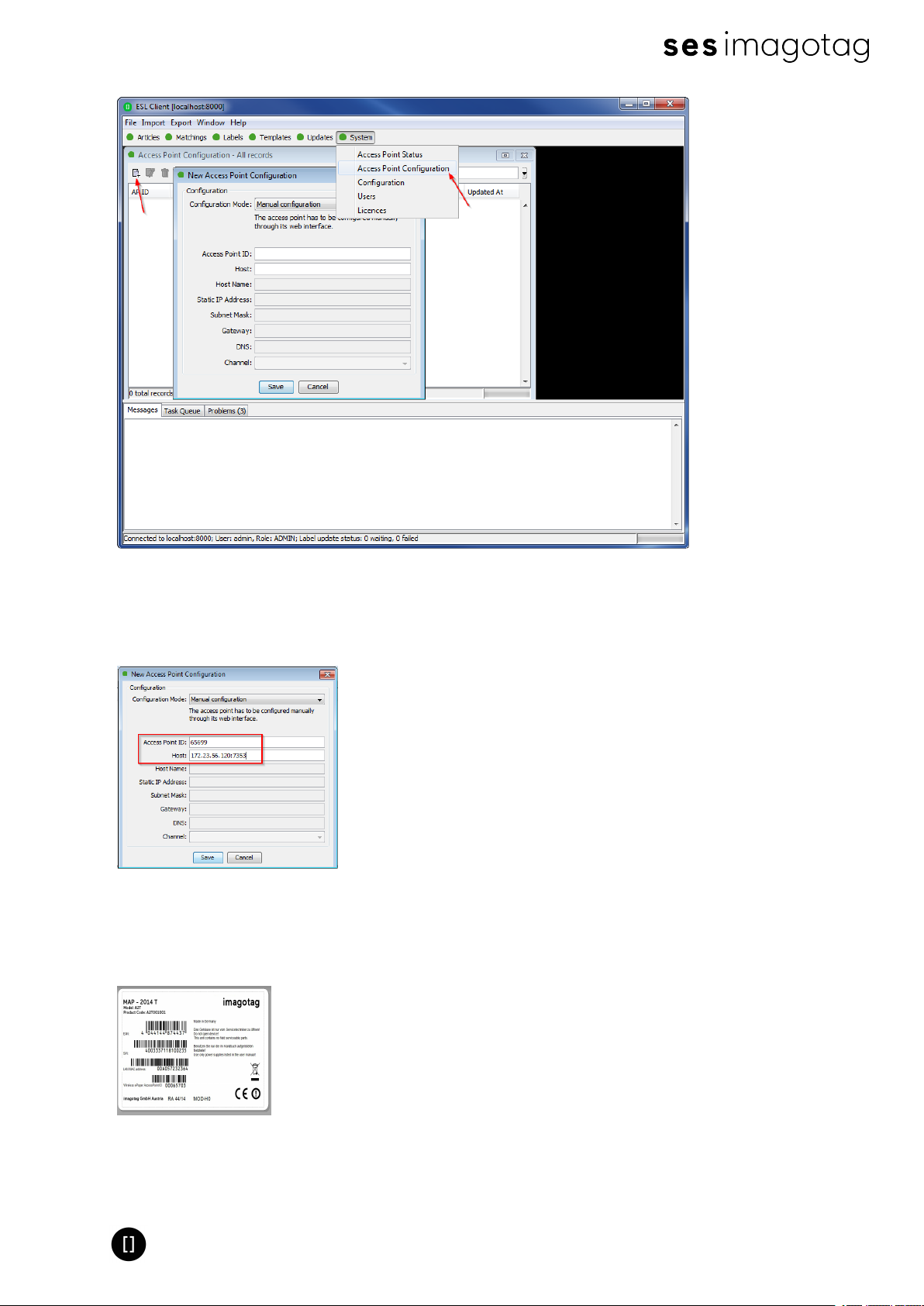
After the configuration in the LANCOM web-GUI it’s necessary to add this AP via the ESL Client:
System -> Access Point Configuration -> New …
Page 24 of 50
Page 25
Quick Start Guide
FIGURE 1-22: Figure - ESL Client AP configuration - System -> Access Pont Configuration -> New
Choose “Manual Configuration” and enter Access Point ID (AP ID), IP address (Host) and correct
port value.
FIGURE 1-23: Figure - New Access Point Configuration
Note: You can find the Access Point ID under “LCOS Menu Tree – Status – Wireless ePaper” or
on the backside of the Access Point, shown below.
FIGURE 1-24: Figure - Wireless ePaper AP-ID on the backside of the Access Point
Page 25 of 50
Page 26
Quick Start Guide
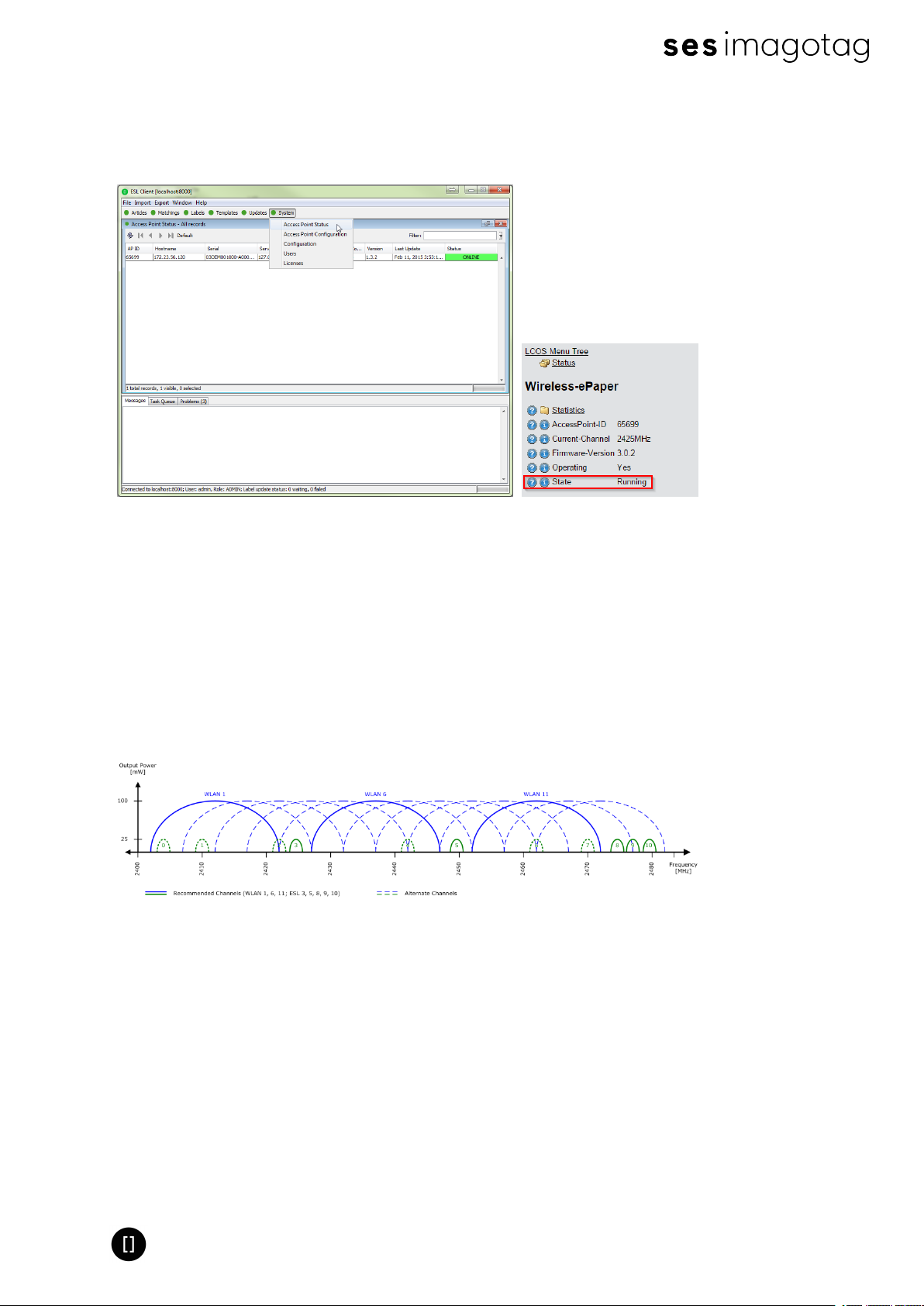
After saving the AP configuration you should see the AP under System -> Access Point Status
as ONLINE. Also the Status in the web-GUI of the LANCOM Access Point changes from State
“Waiting-for-Controller-Connection” to “Running”
FIGURE 1-25: Figure – Access Point and Wireless-ePaper status changes
5.2.8 Automatic channel selection
If you don’t want the Access Point(s) to decide the channels (Automatic selection) automatically
a channel must be selected on each access point in the network. There are 11 non overlapping
ESL channels reserved for the communication with the labels. Five of these channels do not
interfere with typical Wi-Fi installations and should therefore be favored. These are the ESL
channels 3, 5, 8, 9 and 10 and they should be selected if there is a Wi-Fi installation on the WiFi channels 1, 6 and 11.
FIGURE 1-26: Figure - Visualization of used channels of the imagotag AP-2010
Warning: Do not select the same channel on two access points within one area. This will cause
interferences and avoids labels from joining the network. The same channel may only be
selected on two access points if it can be guaranteed that every label is within the range of
only one of these access points.
Page 26 of 50
Page 27
Quick Start Guide
5.3 Selecting channels
For a working installation a channel must be selected on each access point in the network.
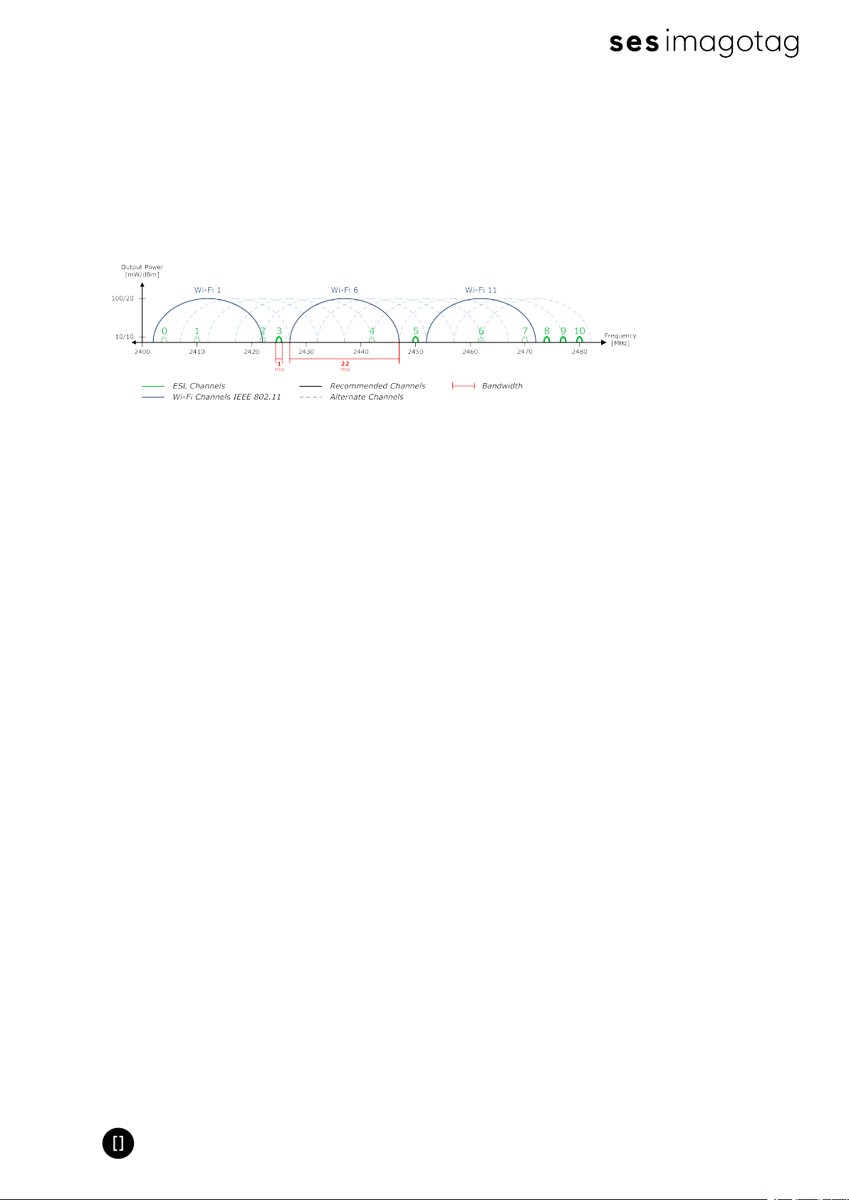
There are 11 non overlapping ESL channels reserved for the communication with the labels.
Five of these channels do not interfere with typical Wi-Fi installations and should therefore be
favored. These are the ESL channels 3, 5, 8, 9 and 10 and they should be selected if there is a
Wi-Fi installation on the Wi-Fi channels 1, 6 and 11.
FIGURE 1-27: Comparison between common used Wi-Fi and ESLchannels
If there is a Wi-Fi installation operating at 2.4 GHz (IEEE 802.11b/g/n) or any other radio
frequency (RF) technology that uses the 2.4 GHz ISM band make sure to select the ESL
channels that are least overlapping with the existing installation. If there is no ESL channel
without any overlapping both the ESL and existing installation should still work but there might
be a reduced overall speed in both installations.
Warning: Do not select the same channel on two access points within one area. This will cause
interferences and avoids labels from joining the network. The same channel may only be
selected on two access points if it can be guaranteed that every label is within the range of
only one of these access points.
Page 27 of 50
Page 28
Quick Start Guide
6 Setup Security
The security concept is based on individual registration codes for each label. Not only that the
new concept simplifies installations, it also provides stronger encryption and a secure key
exchange with individual communication key derived from a user defined network key.
6.1 General encryption features and how does it work
l Solid improved safety
l Encrypted data type AES128 (Advanced Encryption Standard)
l User defined 128 bit network key for each installation
l Key is distributed to labels automatically
The new system requires a user defined 128 bit network key for each installation. The key is
derived from a passphrase that is defined by the customer and stored in the imagotag Core
Service and used by all access points connected to that server to encrypt data communication
to the labels.
A per-label communication key is transmitted to the labels during the registration of them.
Each label is assigned an individual registration code (it combines label ID and PIN code and
it’s an alphanumeric case-sensitive code with 11 characters). The imagotag Core Service will
than automatically start the key exchange with the label secured by the PIN extracted from the
registration code.
6.2 Set the encryption key
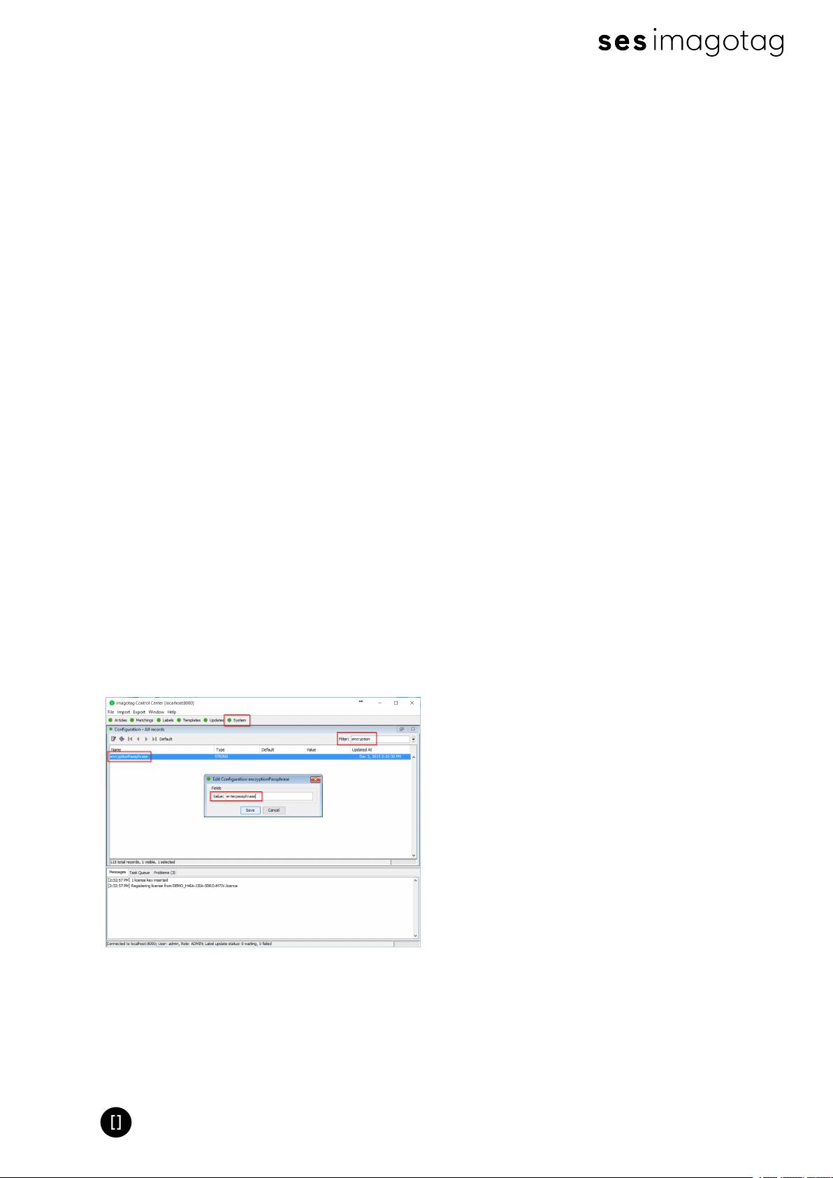
First step is to set the parameter “encryptionPassphrase“ under System – Configuration (you
can choose the encryption Passphrase on your own).
FIGURE 1-28: Set encryption key
Note: Do not change encryption passphrase if labels are already connected and encrypted (if
you want to change the encryption passphrase you’ll first have to unlock all labels – see
[Troubleshooting] on page 45).
Page 28 of 50
Page 29
Quick Start Guide
7 Register labels
In order that labels can join the network it is necessary to register them first.
7.1 General procedure
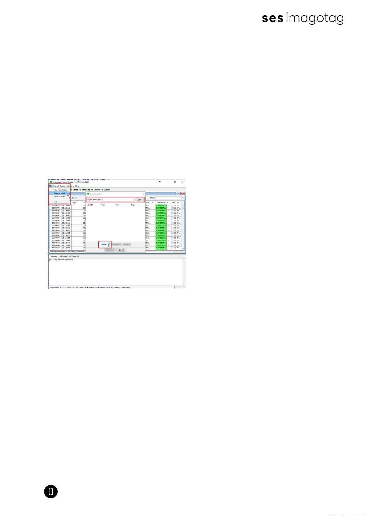
Via the ESL Client under File – Register Labels it’s possible to register your labels manually
with the registration code shown on each single label or you could import a CSV file with your
registration codes. In order to refresh the entries press the refresh button shown in the next
figure.
Important Note: After the registration it could last a certain time until all registered labels are
joined to the network (from 30 minutes up to two hours, depending on configured access point
channels). After this you can send images to each label (see Start tagging on page 35).
FIGURE 1-29: Add/Delete Label and refresh entries
7.2 What's on the label?
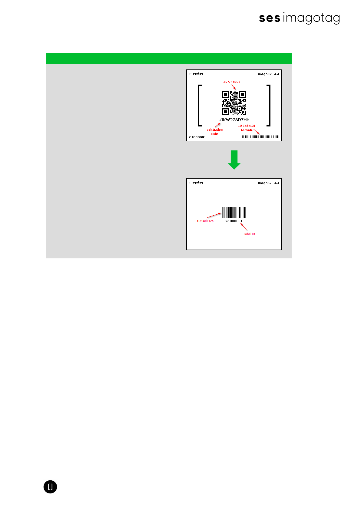
All labels will arrive with its registration code (11-digit alphanumeric)shown on the display of
the label. The code is printed as a 2D QR code, as a 1D Code128 barcode and as human
readable text. The registration process for the customer is easy – he has only to scan one of
this barcodes. The imagotag Core Service will than automatically start the key exchange with
the label secured by the PIN extracted from the registration code.
The two relevant codes:
1. The label ID (8-digit hexadecimal) to identify the label (it's also the radio address which
is similar to a MAC address).
2. The registration code (11-digit alphanumeric) is required to activate the encryption. This
code also contains the label ID and a random PIN code.
Page 29 of 50
Page 30
Quick Start Guide
7.2.1 Labels before and after registration
Page Layouts G1 4.4
Layout when shipped
Registration Page Layout
Note:The label ID can only be read and will not be
displayed as barcode in this layout.
Layout after successful registration
Reset Page Layout
Note: After successful registration, the AES key is
exchanged for encryption and the label switch to a page
where only the label ID is displayed as 1D Code128
barcode.
The sticker (on the bottom and on the back) always contain only the label ID and therefore
should not be used for registration. They are only intended for the later article assignment
(matching process).
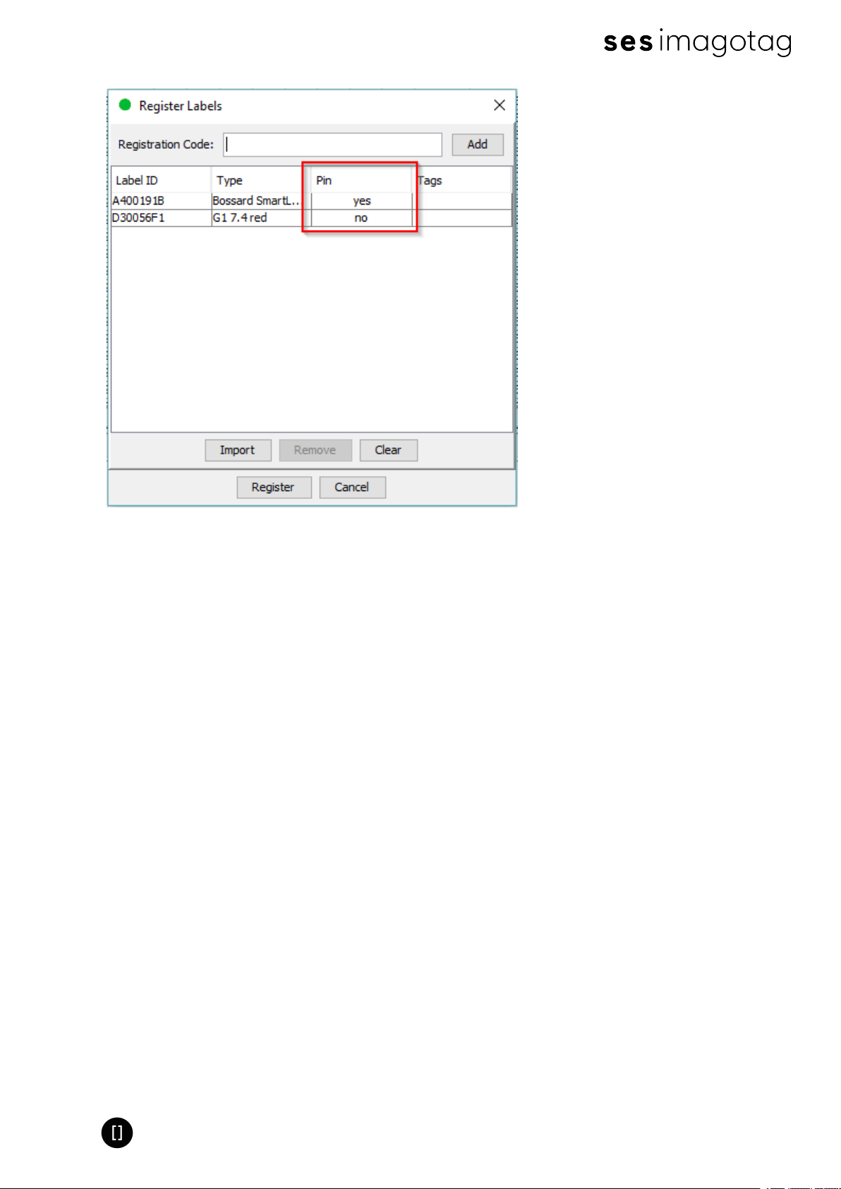
Here you can see the registration dialog in the imagotag Control Center where one single label
has been entered with the registration code (Pin =yes - security enabled)and the other one
with the label ID (for old label versions < 3.0.0, Pin =no, no secured communication).
Page 30 of 50
Page 31
Quick Start Guide
FIGURE 1-30: Register labels dialog (registered with registration code and label ID)
Note: New versions of the imagotag Core Service, imagotag Control Center and AP-2010 (≥
1.3.0) will also support old labels that do not come with a pre-programmed PIN code. New
labels (≥ 3.0.0) will also work in old installations together with old labels but the imagotag Core
Service will not accept registration codes during the registration process. To register the labels
it is required to scan the barcode with the label ID from the backside or the bottom edge of the
label. As the server will not start the key exchange all data is transmitted unencrypted to the
labels.
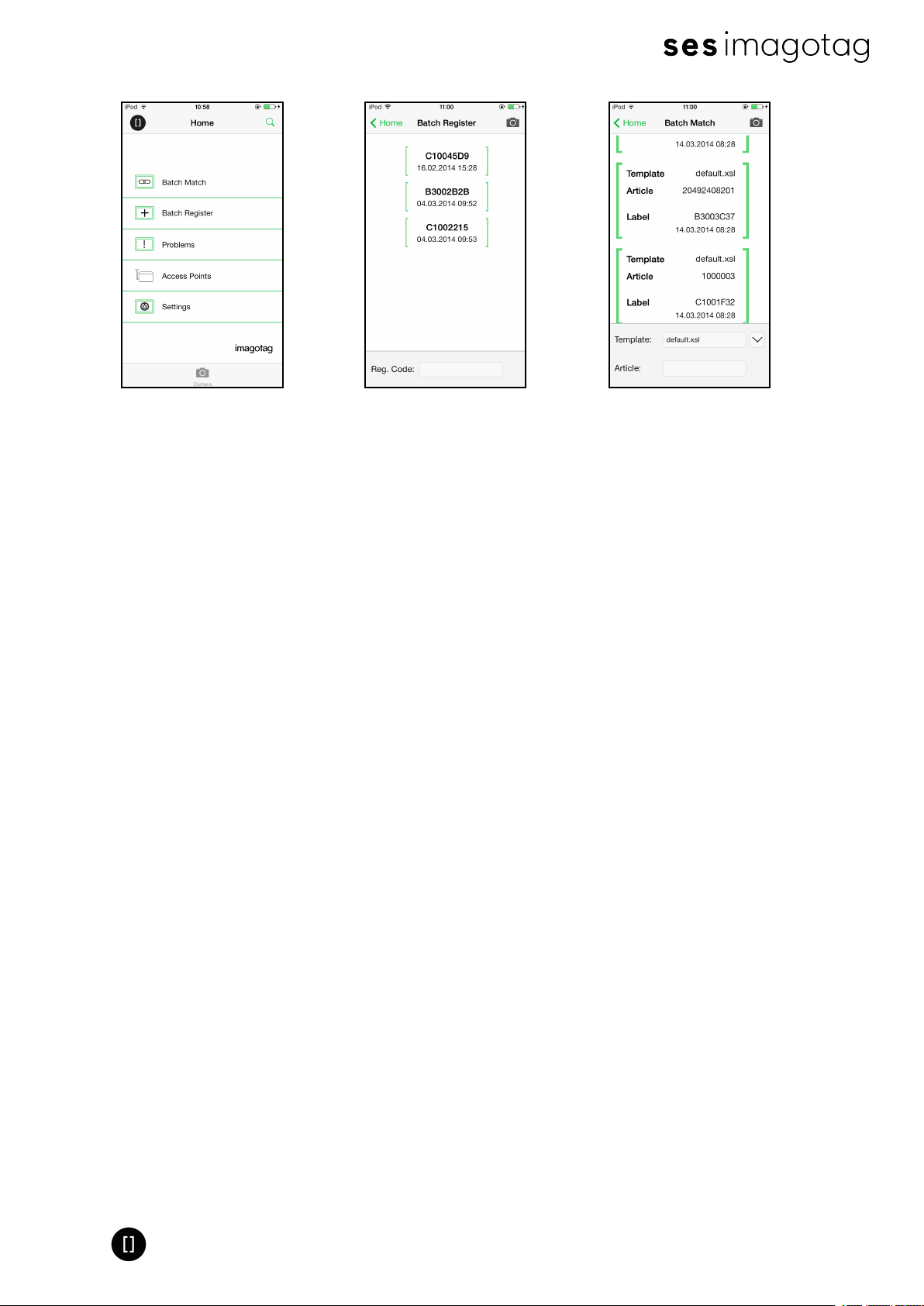
7.3 Handheld terminals, USB barcode scanner and iOS-App
It’s also possible to register labels with a commercial USB barcode scanner (2D/1D). You can
also use our iOS-App (for iPhone and iPod touch, only available on request).
Handheld terminals are mobile devices that are used to manage the ESL installation. If the
handheld provides a barcode scanner, it may be used easily to link articles and labels by
scanning the article barcode (usually EAN, UPC or GTIN) and the unique ID of the label.
Here you can see some screenshots of our iOS-App:
Page 31 of 50
Page 32
Quick Start Guide
FIGURE 1-31: ESL-App Home-Screen FIGURE 1-32: ESL-App Registration
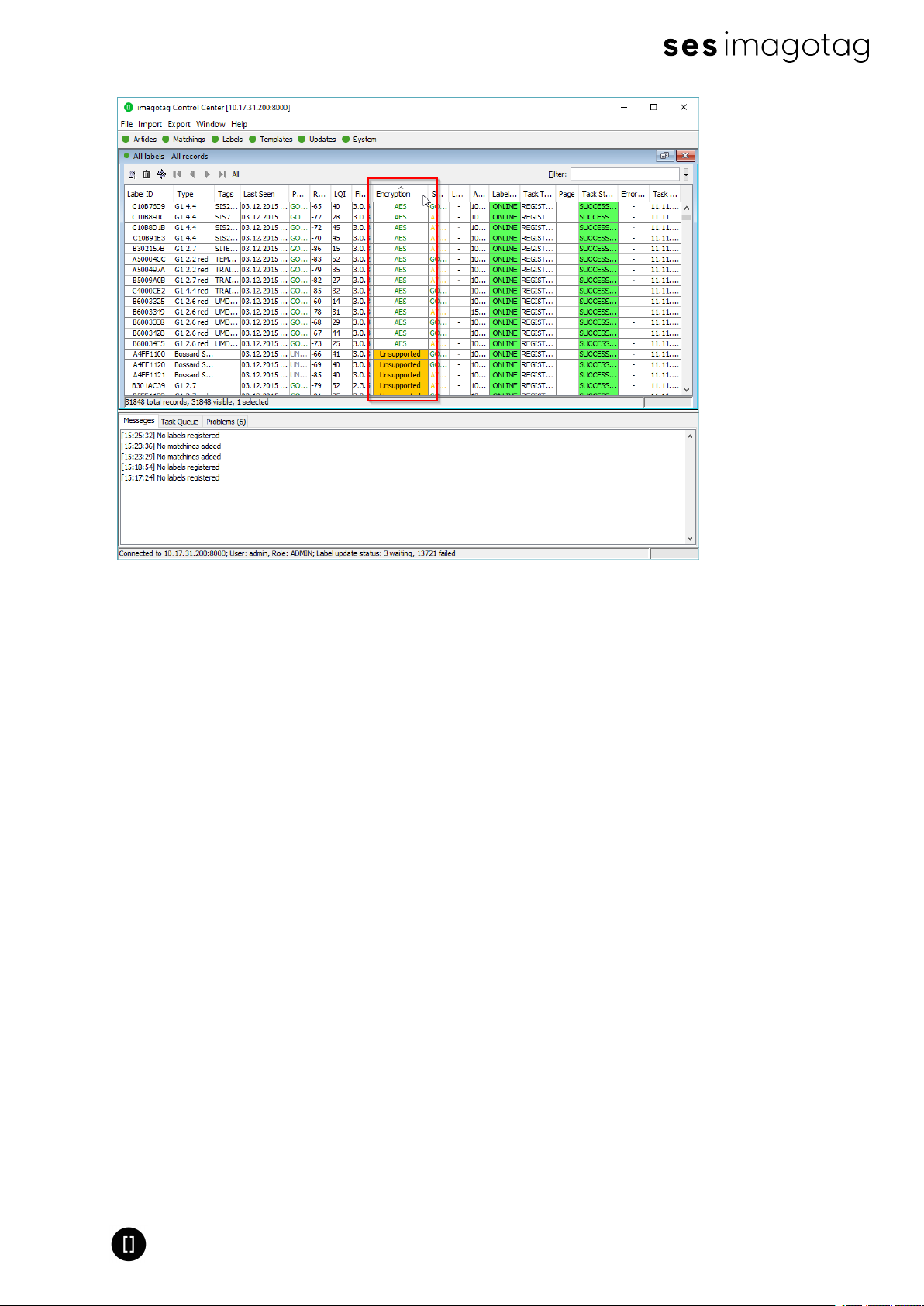
7.4 Encryption status
Here are the encryption status a label could have:
l AES: Communication with label is encrypted with 128 bit AES
l No PIN: Could not set encryption key as no PIN (registration code) was provided
o
Solution: Re-register label with registration code
l Key unset: Communication is NOT yet encrypted
o
Solution: Set encryption passphrase and ping the label to start the encryption process
l Unsupported: Encryption is not supported by label firmware
l Unknown: Security status is not determined yet
Page
FIGURE 1-33: ESL-App Matching
Page
Page 32 of 50
Page 33
Quick Start Guide
FIGURE 1-34: Encryption status
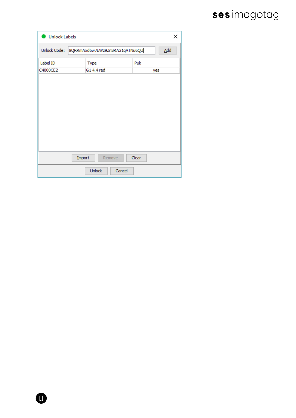
7.5 Unlocking labels
If the label was registered and a communication key was set it will no longer work in other
networks using a different network key passphrase. To unlock this labels for other networks an
unlock code is required. The unlock code is similar to the registration code - it is a combination
of the label ID and a 128 bit PUK code.
Via imagotag Control Centerselect File – Unlock labels and enter the unlock key.
Page 33 of 50
Page 34
Quick Start Guide
FIGURE 1-35: Unlock Labels Dialog
Note: The unlock-code for the specific labels is enclosed in the Smart Box (in an envelope).
Page 34 of 50
Page 35

Quick Start Guide
8 Start tagging
8.1 What can I do now?
As soon as labels are online you can do several things:
Send images to labels, assign tags, show the current images, ping labels, reset labels (reset
display to show label ID and label ID barcode), refresh displays, switch to a preloaded page,
create a new matching (or multi-matching/multi-facing), set (extended)filters, check update
logs, ...
8.2 Sending pictures to labels
1. Right click on one or more labels -> Send image…
2. Select a picture (Note: Display size must match the resolution of the image)
A. In the right pane, a priority (currently not relevant) could be set for the task, as well
as the Page to which the image should be sent and whether the image is preloaded.
B. If preloaded, the image is placed in the memory of the label, but not yet displayed.
The image change will only be performed after the change to the relevant page.
This allows for each label that images are cached on the various pages and be
accessed quickly by switching to the relevant page.
3. By clicking on “open” the corresponding task(s) for the label(s) will be created and the
transfer begins.
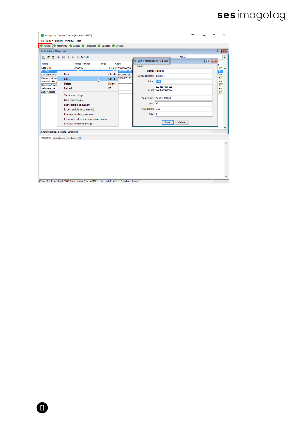
8.3 Article management
For complete management of your articles select Articles – All Articles in the imagotag Control
Center. Here you’re able to create/delete and edit your articles.
The Smart Box comes with 8 predefined articles which you can see here. You can add some
more demo articles, edit the existing ones or just step further to the next point Matchings.
Page 35 of 50
Page 36
Quick Start Guide
FIGURE 1-36: Article management
8.4 Matchings/Multi-Facing
The logical link between articles and the label that shows the article information and price of
this articles is called matching. With a matching the layout of the image rendered for the label
is also defined by specifying the name of a template.
In a more technical way a matching is the triple of:
l Label ID
l Article number(s) or GTIN
l Name of the template file
Note: Only one matching per label is allowed but articles may be matched to more than one
label.
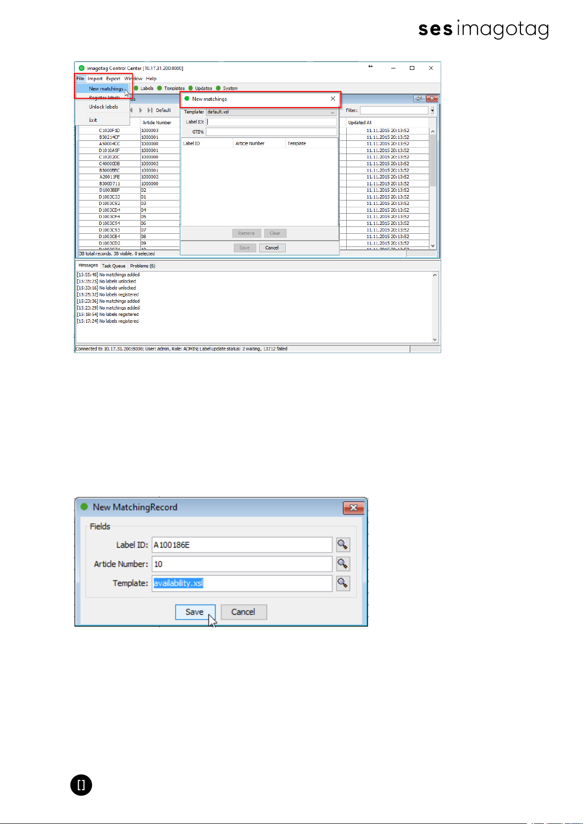
Select File – New matchings to open the dialog where you can select the desired data records
and create a number of matchings at the same time. To generate a multi-matching, multiple
article numbers separated with a comma have to be specified. Keep in mind that your template
has to be able to render a image for multiple articles.
Page 36 of 50
Page 37
Quick Start Guide
FIGURE 1-37: New matchings dialog
Another way to create/edit matchings is under “Matchings – All Matchings”:
l Select the desired data records (Label ID, Article Number) in the following window “New
Matching Record“ (either manually or with the magnifying glass symbol). Select an appro-
priate template via “Template” that should be used to generate the image.
l Confirm your choice by clicking Save. After that, the generated image is sent to the selec-
ted label.
FIGURE 1-38: Create a matching
It’s also possible to create Matchings with imagotag Control Center under Labels and Articles,
for this just select the desired article or label, right-click on it and select “New matching…” (the
new matching dialog will be pre-filled with the article or label information).
Page 37 of 50
Page 38
Quick Start Guide
8.5 Set (extended) filters for enums
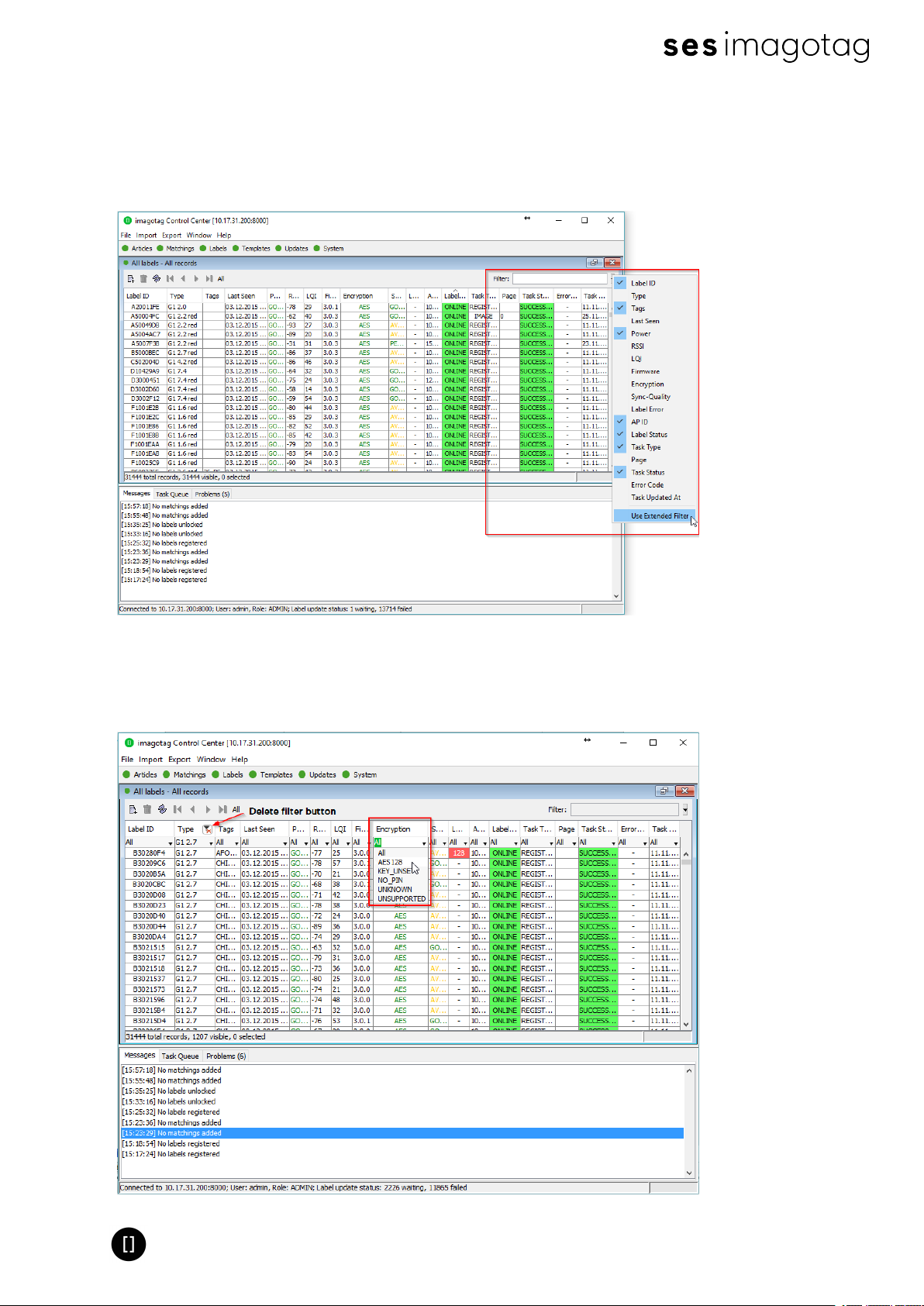
There are various filter options. Besides the known filter options you'll now have the possibility
to set extended filters. Enable/disable the extended filter as shown in image below.
FIGURE 1-39: Use and enable the extended filter mode
With the extended filter options it's possible to set and combine several filters. Click on the
drop down menu to see the different choices.
Page 38 of 50
Page 39
Quick Start Guide
FIGURE 1-40: imagotag Control Center extended filter options
8.5.1 Extended filter operators
The following operators are available:
Operator Description
< Less than
> Greater than
<= Less than and equal
>= Greater than and equal
! Negation (Not)
= Equals
:
Defines a range (e.g. RSSIfilter -65:-75 shows all labels with current
RSSIvalue within -65 and -75) Doesn't apply to date and text.
8.5 Templates
The template is used to specify the fields, which should be rendered into the image. The
imagotag Core Service can handle multiple templates.
8.5.1 General information about templates
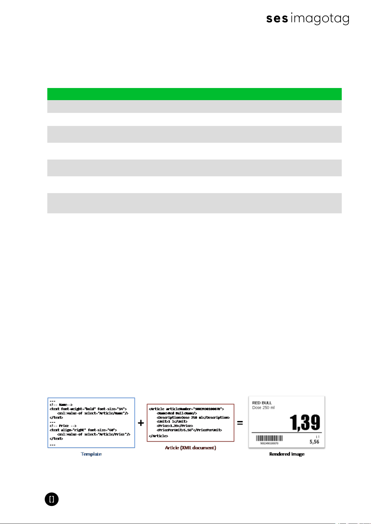
The image rendering process is based on XSL (EXtensible Stylesheet Language) templates.
The individual image for the label is then generated by applying the template to a XML, which is
based on the properties of the label and is expanded by a custom XML from the user.
The following steps are executed when processing a template:
l Generating a record XML based on the label/task information and custom information
provided by the user
l Applying the template (XSL) on the generated record XML. This results in a document
containing the fields, specified in this reference and values referenced from the XML
l Rendering the image (*.PNG) based on the previous output
FIGURE 1-41: Input and result of the rendering process
Page 39 of 50
Page 40

Quick Start Guide
8.5.2 Template Editor
In order to use our rendering engine you must know our template language which is basically
XSL. We do also have a Template Editor with live preview, but you need a little bit time to setup
everything and get familiar with it. Therefore we suggest to send pre-rendered images to labels
(right-click on a label -> send image) which you can create with every image manipulation
software you want (e.g. Gimp, Photoshop, Paint, …). You can even take some pre-rendered
images from us for each label type with the correct resolution as a template – you’ll find some
in the client’s directory under data/images.
Page 40 of 50
Page 41
Quick Start Guide
8.5.2.1 Starting Template Editor
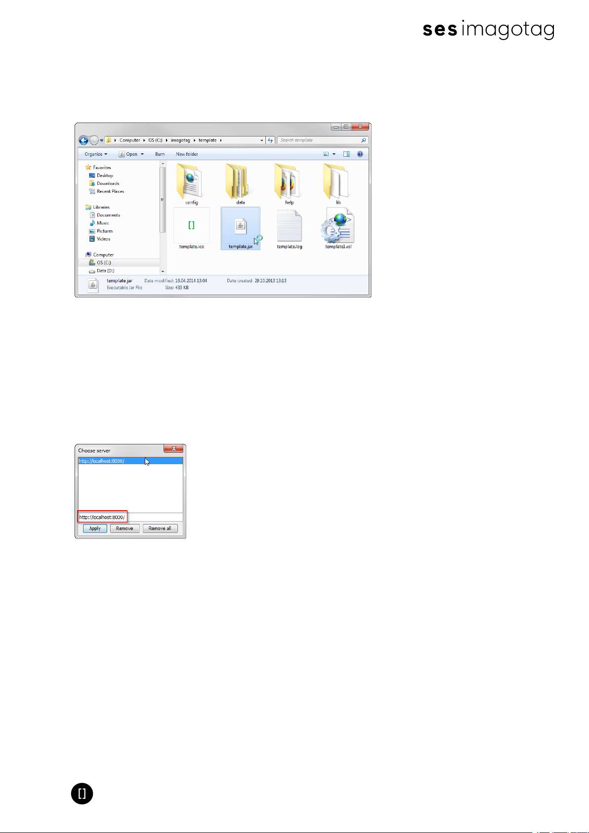
Navigate to the unpacked template directory (see point Installation process on how to unpack
the software package) and execute the “template.jar” file (see [Troubleshooting] on page 45).
FIGURE 1-42: Starting the Template Editor
8.5.2.2 Open default template-file and load records from server:
l Open the Template Editor by clicking the “template.jar” file located in the template-dir-
ectory (In our example it should be C:\imagotag\teamplate\).
l Next step is to create a new template file or to open an existing one (The default.xsl tem-
plate file is located in the server-directory under C:\imagotag\server\data\template\).
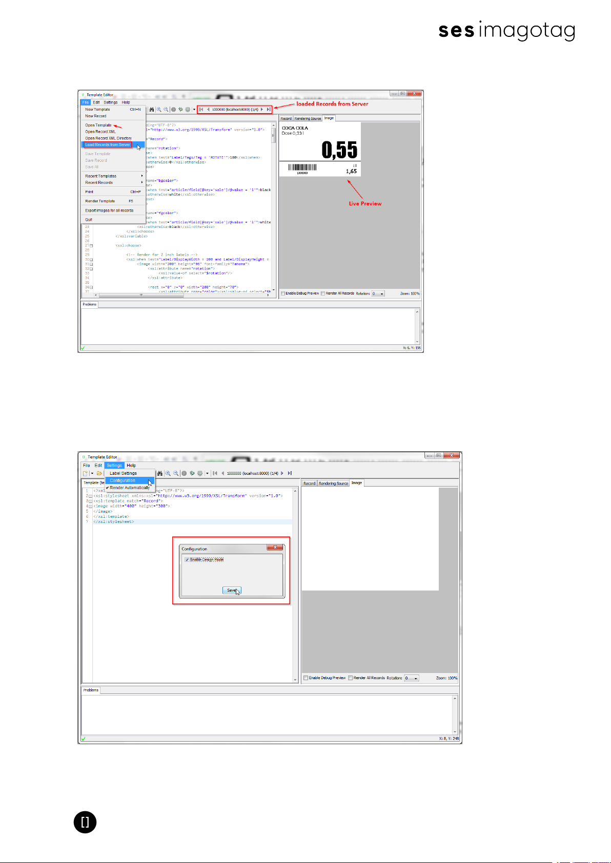
l To get a live preview you’ll have to load some records, in our case we load the demo art-
icle records from our running server, see the following figure.
FIGURE 1-43: Load Records from Server
Page 41 of 50
Page 42
Quick Start Guide
After these steps your Template Editor window should look something like this:
FIGURE 1-44: Template Editor with loaded records from server and default.xsl template file
8.5.2.3 Design Mode
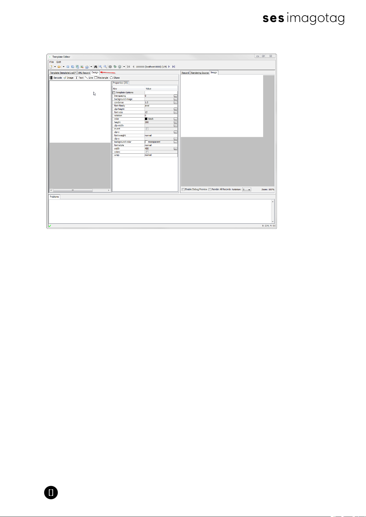
You can enable the graphical Template Editor by selecting Settings – Configuration – tick
Enable Design Mode and finally the Save-button.
FIGURE 1-45: Enable Design Mode in Template Editor
Page 42 of 50
Page 43
Quick Start Guide
After enabling the Design Mode a new tab will show up.
FIGURE 1-46: Template Editor Design Tab
8.5.2.4 Enable and show color red
As there are new label types which are capable of showing the color "red"there's a short
description how to enable this inside the xsl template file.
l Optional: Query whether it is a "red" label
l
<xsl:when test="Label/DisplayWidth = XXX and Label/DisplayHeight =
XXX and Label/DisplayColors = 'BLACK_WHITE_RED'">
l Add colors option to image tag:
l
<image width="XXX" height="XXX" colors="true" font-family="XXX">
l Show something in color red, e.g. text:
l
<text font-size="XXX" condense="XXX" font-weight="XXX" color=”red”>
8.5.2.5 Help Content
There’s a link to the Help content for the Template Editor, open it by clicking Help – Help
Content in the Template Editor or open the file index.html located in
C:\imagotag\template\help\.
Also you can find further information on the USB Stick under Documentation - Image Rendering
Reference.
Page 43 of 50
Page 44

Quick Start Guide
9 Integration
9.1 Webservice integration
The ESL server provides access to its interfaces methods through a RESTful web service API.
The web service is designed according to the “Representational State Transfer” (REST)
architectural pattern.
The ESL server listens for incoming HTTP web service requests on the TCP port 8001 by
default.
You can find further information and documentation about the webservice integration online
under https://portal.imagotag.com/get/documentation
9.2 Plugins
We provide several plug ins which are used for importing article information into the ESL
Server.
You can find further information and documentation about our integration plug ins online under
https://portal.imagotag.com/get/documentation
9.3 Custom integration
For custom integration we provide a Plugin-Interface. Software development service is
available from imagotag software development team or third-party integration partners.
For pricing get in touch with our sales agents ([email protected]).
Page 44 of 50
Page 45
Quick Start Guide
[Troubleshooting]
1 FAQ
If you run into any errors during connecting or sending images to labels, please refer to the
documentation included in the server. This documentation can be found in the AP-2010 web UI
of the server under “Documentation”.
l For problems updating the labels (error code column in labels window) refer to “Update
Error Codes” or (task status column in labels window) refer to “Task Status”
l For connection status problems refer to “Connection Status”
l For label hardware errors (label error column in labels window) refer to “Label Error
Codes”
Code Problem Solution
1 Label not licensed
3 Label not registered
10
11 Error during image rendering Check template (wrong or faulty)
12 Error during image conversion
13 Invalid page
14
20 Template not found Check template directory for missing template file
21 Error during template parsing Correct template file (Invalid content found)
22
30
62
64
Image does not match display
size
Could not process task because
there are unfinished tasks waiting
for this label
Error during content document
creation
Could not send update because
label has insufficient power to
perform the update
HTTP communication error with
the access point
Task was removed from pipeline
The label is not licensed. Import the proper license
file for the label or check for typos in the label id.
The label may have been deleted or has never been
registered at all. Register label.
The size of the image does not match the label’s
display size. Please check the width and height of
your image and look up the display size in pixels for
the label. These sizes have to be equal.
Change format of the image to standard format (e.g.
PNG or BMP)
Page not supported by label type, choose a different
page
Abort task or wait until unfinished tasks are
finished
Check server and article record configuration
The power status of the label is “Bad”, which means
it is very low on battery that in may not accomplish
the display update. Replace the battery of the label.
The server was not able to send the task to the
Access Point. Please make sure that the Access
Point is not offline (System -> Access Point Status)
and there is an established network connection
between Access Point and Server.
Resend the corresponding task(s)
Page 45 of 50
Page 46

Quick Start Guide
because previous transmission
was not finished in time
80
92 Task type not supported Upgrade AP software to process this kind of task
Error while writing task to
database
Check database connection
Page 46 of 50
Page 47
Quick Start Guide
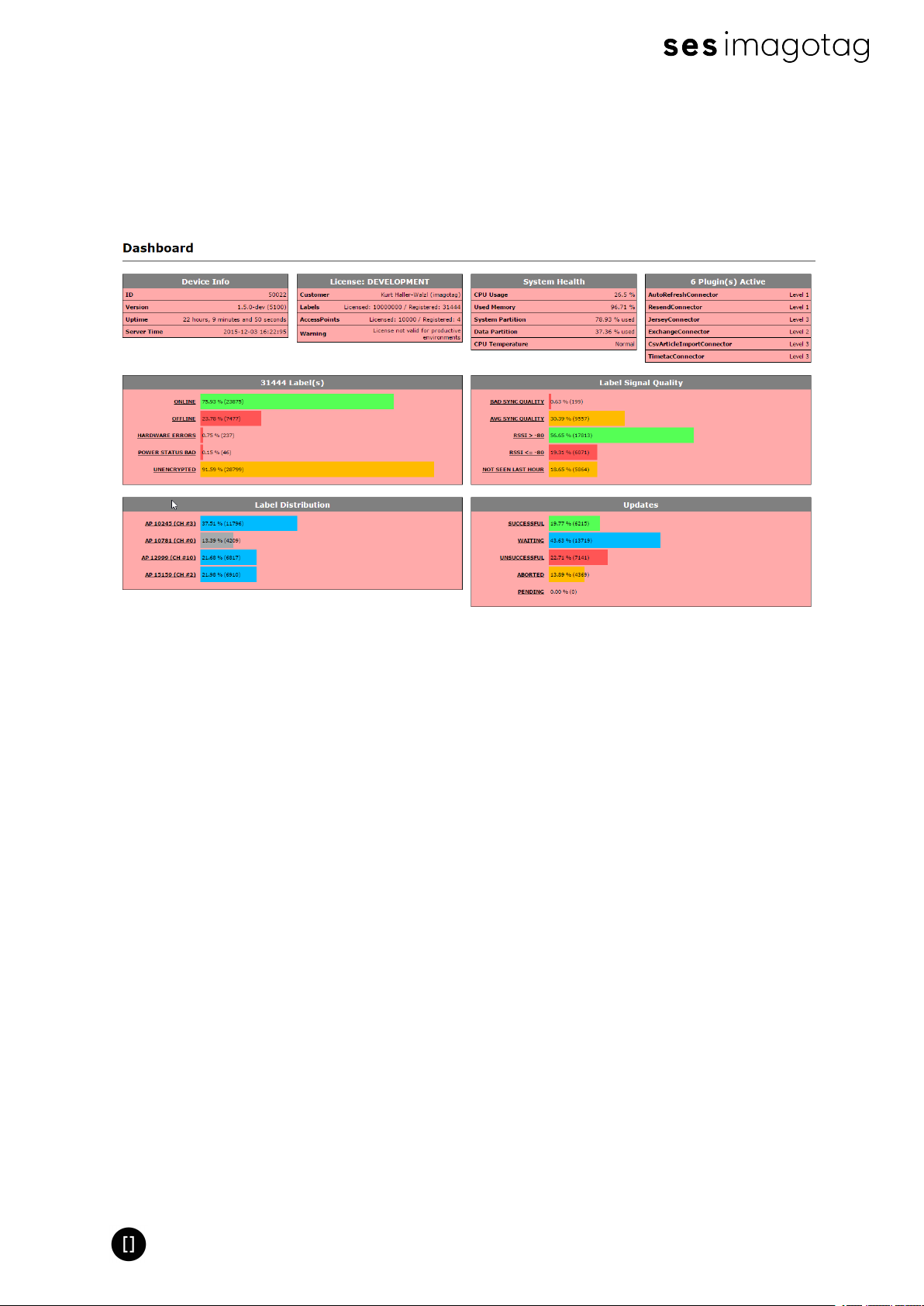
1.1 imagotag Core Service Dashboard
To get a better overview accross your complete ESLsystem you can use the new dashboard.
All kind of helpful information is collected here. You'll find the dashboard under http://<core-
service-ip>:<port>/service/dashboard.xml
1.2 Running the imagotag Core Service as a background service
The imagotag Core Service may be started as a normal application, but on a productive system
it is usually required to have it automatically started without a user logged in. To achieve this
the imagotag Core Service can be registered as a Windows service. It is than started
automatically without any graphics user interface.
To install the imagotag Core Service as a Windows service the batch file install_service.bat is
provided. If this file is executed with administrator privileges (Right click – Run as
Administrator) it will install the imagotag Core Service installation from the same directory as a
Windows service with the name ESL_SERVICE.
The file uninstall_service.bat will remove the Windows service if executed with administrator
privileges.
If you have any problems regarding the background service:
l Check if you have installed the correct JAVAversion corresponding to your system
(x86/x64)
l If the imagotag Core Service is already installed as a Windows service you have to unin-
stall it first (uninstall_service.bat) and reinstall it again (install_service.bat).
Page 47 of 50
Page 48

Quick Start Guide
1.3 Where can I find the license file for my SmartBox?
You find the license file (which has to be activated at the imagotag Customer and Partner
Portal enclosed in the SmartBox in a "License Envelope".
1.4 Deleting the demo articles
In order to prevent the example articles from being re-added to the server, go to "System Configuration"and set the "importFixtures"variable to false.
1.5 Labels don’t come online
After the registration it could last a certain time until all registered labels are joined to the
network (up to two hours, depending on number of access points and the channels used.
l Up to 30 minutes with channels 3, 5, 8, 9 and 10
l Up to 2 hours with channels 0, 1, 2, 4, 6 and 7
Warning: A label must not be registered to multiple imagotag Core Service installations at the
same time. It will only connect to one of this installations.
1.6 The encryption does not work
Check the encryption passphrase in Server Configuration (System – Configuration).
If label was already registered with a different passphrase you’ll have to unlock the label first in
order to register it on the server.
1.7 Unlocking labels
If the label was registered and a communication key was set it will no longer work in other
networks using a different network key passphrase. To unlock this labels for other networks an
unlock code is required.
Select File – Unlock labels and enter the unlock key.
The unlock-code for the specific labels is enclosed in the Smart Box (in an envelope).
If you have any problems (the unlock code wasn't included or you can't find it) please contact
the imagotag support ([email protected]).
1.8 Starting Java applications
Before starting a Java application, make sure you have Java Runtime Environment Version 6 or
higher installed and you have set the necessary environment variables.
Page 48 of 50
Page 49

Quick Start Guide
If the .jar file extension is known and associated with Java, just double-click the jar file to start
the application. Otherwise if the extension is not recognized:
Windows:
Create a shortcut of the jar file, right-click on it and open properties. Prepend “javaw.exe –jar“
to the path in the “Target” field. Double-click the shortcut.
Linux:
Navigate via command line to the directory where the jar file lies and execute “java –jar
<filename>.jar”
In case your environment variables are not set properly (e.g. javaw.exe/java command could
not be found) do the following steps:
1. Locate your installation directory of your Java Runtime Environment
2. Set JAVA_HOME Variable
Page 49 of 50
Page 50

Quick Start Guide
Under Windows:
l Right-click on “My Computer” and select “Properties”
l Click the advanced tab
l Click the “EnvironmentVariables” button
l Under “SystemVariables”, click New.
l Enter the variable name as JAVA_HOME
l Enter the variable value as the installation directory of your Java Runtime Environment
l Click OK
l Look for the Path variable in “SystemVariables” and edit it
l Append a semicolon (;) and %JAVA_HOME%\bin to it
l Click OK
l ApplyChanges
Under Linux:
l Use the “export” command to set your variables
l export JAVA_HOME=<pathToJRE>
l export PATH=$PATH:<pathToJRE>/bin
l In order to make these changes persistent, write them into your .bash_profile file and use
“source ~/.bash_profile” to apply the changes
1.9 Encoding problems
Per default, UTF-8 encoding is used. If you have any problems regarding encoding you can force
any java application to use UTF-8. By setting the (Windows) environment variable JAVA_TOOL_
OPTIONS to -Dfile.encoding=UTF8, the (Java) System property will be set automatically every
time a JVM is started.
1.10 Further documentation
Please visit https://portal.imagotag.com for further documentation:
l Developer Reference (Web Service)
l Image Rendering Reference
l CSV/XML Import Plugin
l File Import Plugin
l Core appliance service mode reference
l (M)AP Update HowTo
l Core Suite Update
l Security Whitepaper
l Licensing Whitepaper
Page 50 of 50
 Loading...