

Servis WASHING MACHINE User Manual
W ASHING MACHINE
OWNERS HANDBOOK
CUSTOMER CARELINE
08705 168299
W A S H I N G M A C H I N E
Customer Careline: 08705 168299

W A S H I N G M A C H I N E
Thank you for purchasing a Servis Washing Machine.
The responsibility for correctly installing your washing machine rests entirely
with you, the owner, so please read the safety and installation instructions
carefully. Remember, it may be necessary to pull your appliance from its
working position for servicing so do not make the water and electrical
connections too short.
Do not tamper with the appliance until you have read and understood the
instructions fully.
INDEX
INTRODUCTION
Safety Instructions 2
INSTALLATION
Unpacking Instructions 3
Electrical Information 4
Levelling the Appliance 6
Plumbing Installation 7
OPERATION
How to Do a Wash 11
Laundry Preparation 13
Loading the Appliance 13
HINTS & ADVICE
Detergents and Additives 14
Care of Your Appliance 15
Stain Removal 17
Troubleshooting 19
AFTER SALES SERVICE 20
1

W A S H I N G M A C H I N E
SAFETY INSTRUCTIONS
1 Please read the installation and connection instructions before attempting to install this appliance.
2 Ensure you have followed the 'Unpacking Instructions’ section carefully.
3 You should run an initial wash cycle without laundry to remove residues of factory-applied grease from
the drum and tub. We suggest a rinse and spin programme with a small amount of detergent.
4 It is important that when you have selected a rinse and spin programme, you attend the machine
throughout the cycle, which will also ensure that all installation connections have been correctly made.
5 It is also recommended after seven days use, that the connections to the outlet hoses are checked at the
taps and the appliance.
6 You may find some water deposits in the tub; this is the residue from the thorough testing, which your
appliance was subjected to in the factory.
7 Before using your appliance for the first time, please make sure that the mains voltage and supply
indicated on the rating plate (situated inside the filter door on the front bottom right hand corner of the
appliance) agree with the mains voltage where the machine is to be used.
8 Before cleaning or care and maintenance work, make sure that the appliance is switched off. For safety
reasons we strongly advise that you pull the mains plug out of the socket, switch off at the power point
or completely remove the fuse box servicing the circuit (see Electrical Information).
9 Never direct water onto the outer casing of the appliance.
10 Never use the supply lead to pull the mains plug out of the socket. Pull the plug.
11 Never operate the machine if the appliance shows visible signs of damage to the control panel, worktop
or bottom plinth.
12 We advise that for your safety and the continued trouble free operation of your appliance, all repairs and
maintenance should be carried out by an approved Servis UK engineer using only genuine parts.
13 Children may not realise the dangers of improper use of electrical appliances. Therefore, please ensure
that children are kept away at all times.
14 During certain programmes, the glass on the porthole door could become very hot, please ensure
therefore that children are kept away at all times.
15 When it is finally time to replace your washing machine, please make sure that you de-activate the door
lock and cut the electrical supply lead, (after disconnecting) and dispose of the lead and plug safely.
16 If you operate this appliance incorrectly or use it for any purpose other than that for which it is intended,
we cannot accept liability for any possible damage caused.
17 When cleaning the stainless steel drum, never use any iron-containing scouring agents or steel wool.
18 If the supply cord is damaged, it must be replaced by the manufacturer or its service agent.
19 The appliance must be positioned so that its plug is easily accessible. It is also important that your
appliance has adequate ventilation and that air flow underneath the appliance is not impeded.
WARNING! Socket outlets are not permitted in bathrooms, neither should any provision be made for
connecting moveable electrical appliances. No stationary appliance is to be installed within reach of a person
using a bath or shower.
2
W A S H I N G M A C H I N E
UNPACKING INSTRUCTIONS
1 Washing Machine
2 Owners Handbook
3 Hot and Cold High Pressure Hoses
4 Plastic Hole Plugs
5 Water Inlet Cap
6 Rubber Washers
7 Mesh Filters
8 Hose Crook
To protect your new washing machine during transit, several internal components have been secured using
transit screws; these must be removed before using the machine.
NEVER remove the top or back panel whilst the machine is plugged into the electricity supply.
PLEASE NOTE: The transit packaging must be removed before the machine is connected to the power supply.
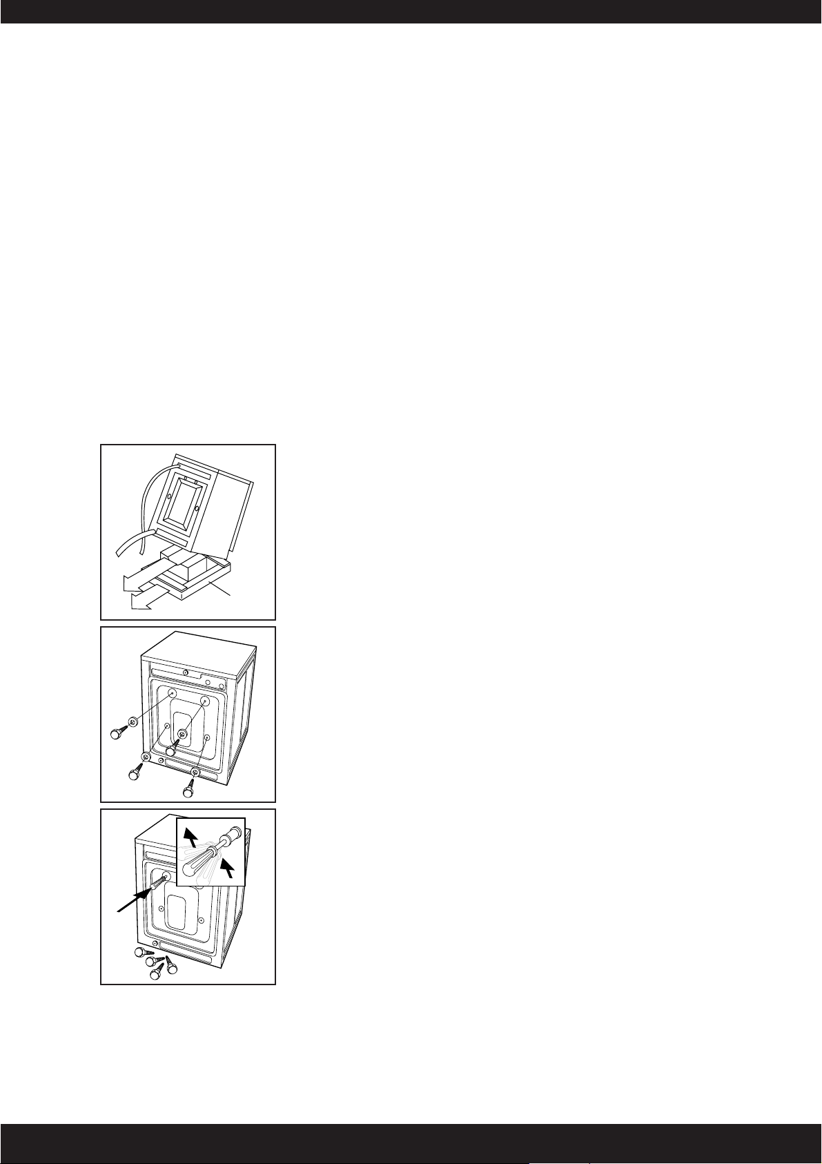
Removal of the transit packaging
Fig 1
Fig 2
Fig 3
A
H
1 Remove all outer packaging from the machine (Fig 1).
2 Remove packaging base (Fig 1).
3 Remove the four screws using a 10mm spanner (A-B-C-D) (Fig 2).
4 Insert a screwdriver in the holes that have been freed up and wobble the
screwdriver to loosen the spacers (Fig 3) so they can be easily removed.
Store the screws and spacers safely in case the appliance needs to be moved
at a later date. If left in the appliance the spacers could cause damage.
5 Fill in the four holes with the four plastic hole plugs you can find in the
user instructions bag (item 4).
Replacing the Spacers
Should you need to move the appliance to another location, the
following steps should be taken before transportation.
1 Disconnect the appliance from the electricity supply.
2 Remove the four plastic hole plugs.
3 Insert spacers (Fig 3).
4 Insert the four screws and washers A-B-C-D and re-tighten (Fig 2).
3
W A S H I N G M A C H I N E
ELECTRICAL INFORMATION
Before using this appliance ensure that the voltage in your home corresponds with the voltage indicated on
the machine rating plate, which can be found inside the filter door - front bottom right hand corner.
Warning – This appliance must be earthed.
The mains lead of the appliance is fitted with a BS 1363A 13 amp fused plug.
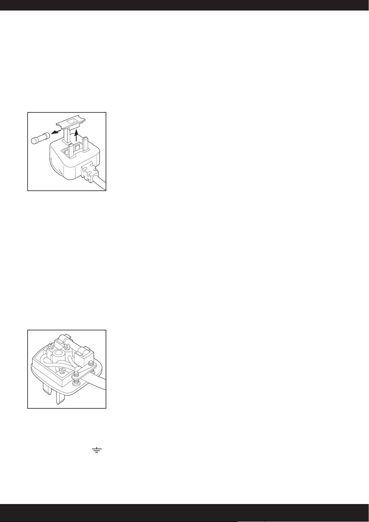
To change a fuse in this type of plug, proceed as follows:
Fig 4
Important:
1 The fuse cover must be replaced after changing a fuse.
2 In the event of a fuse cover being misplaced, the plug must not be used until a correct replacement is fitted.
3 Please ensure that the replacement fuse cover is of the same colour as the insert or has the colour
embossed in words on the base of the plug.
4 For replacement fuse covers please consult your local electrical store.
Please state the colour of your plug insert.
If the fitted plug is not suitable for your socket outlets, it should be cut off and disposed of immediately to
avoid a possible shock hazard should it be inserted into a 13 amp fuse elsewhere. A suitable alternative plug
should then be fitted to a cable.
1 Remove the fuse cover (A) and the fuse (Fig 4).
2 Fit a replacement fuse which should be BS 1362 13 amp.
Warning – This appliance must be earthed.
Important: The wires of the mains lead fitted to this appliance are coloured in accordance with the following code:
Fig 5
As the colour of the wires in the mains lead fitted to this appliance may not correspond with the coloured
markings identifying the terminals in the plug 9 (Fig 5), proceed as follows:
1 The GREEN & YELLOW wire must be connected to the terminal in the plug which is marked with the ‘E’ or
by the earth symbol or coloured green or green and yellow.
2 The BLUE wire must be connected to the terminal, which is marked with the ‘N’ or coloured black.
3 The BROWN wire must be connected to the terminal in the plug, which is marked with the ‘L’ or coloured red.
4 If the terminals in the plug are unmarked or if you are in any doubt as to the correct connections, consult
a qualified electrician.
1 GREEN AND YELLOW – EARTH
2 BLUE – NEUTRAL
3 BROWN – LIVE
4

W A S H I N G M A C H I N E
For the Republic of Ireland only
The information given in respect of Great Britain will frequently apply, but a third type of plug and socket is
also used, the 2-pin, side earthed type. In this case, the wire, which is coloured green and yellow must be
connected to the earth contact and the other two wires to the two pins, irrespective of colour. The supply to
the socket must be fitted with a 16 amp fuse.
Warning
Do not plug a tumble dryer and washing machine into an adaptor for connection to a single socket outlet.
Plug the dryer and washing machine into separate socket outlets.
Special Electronic System
Your appliance is fitted with a special electronic system that allows your appliance to spin at very high speed
if the load is distributed correctly. Prior to spin, the electronic system allows the drum to rotate in both
clockwise and anti-clockwise directions to distribute the wash load evenly. If this doesn't happen, sometimes
large towels and sheets tangle into a ball, the electronic system will recognise the imbalance in the drum and
reduce the spin cycle. This will result in the wash items being more damp than usual.
Where the imbalance is significant and could be detrimental to the appliance the system will automatically
halt the spin cycle. The wash items will therefore be wet.
If this happens, wait until the door safety inter-lock has released the door catch, remove the clothes, spread
them out inside the drum and then reset the appliance to the spin programme.
Note: If your appliance stops and your wash items are wet or more damp than usual, this is not a fault.
The electronic system is there to protect your appliance against excessive movement and vibration.
5

W A S H I N G M A C H I N E
LEVELLING THE APPLIANCE
Having completed the electrical connections, move your appliance to its operating position. To minimise
vibration and noise during spinning your appliance must be level and in firm contact with a well supported
or preferably solid floor. Failure to level the appliance could lead to instability and consequent damage to
adjacent equipment.
Suspended, wooden floors or plinths might be needed to distribute the weight evenly.
Fig 6
Fig 7
1 One or both of the front feet should be adjusted in order to level the
appliance. The back feet also need to be secured by adjusting the nuts.
(Fig 6).
2 Screw the foot up or down until the appliance is level in both front to rear
and side to side directions. Turn feet clockwise to lower the appliance
(Fig 7).
3 Lock the feet by screwing up the nuts using a 16mm spanner so that they
are in firm contact with the underside of the machine (Fig 8).
Fig 8
6
 Loading...