

Page 1
1 of 4
CEV Metal Bonnet Installation Instructions
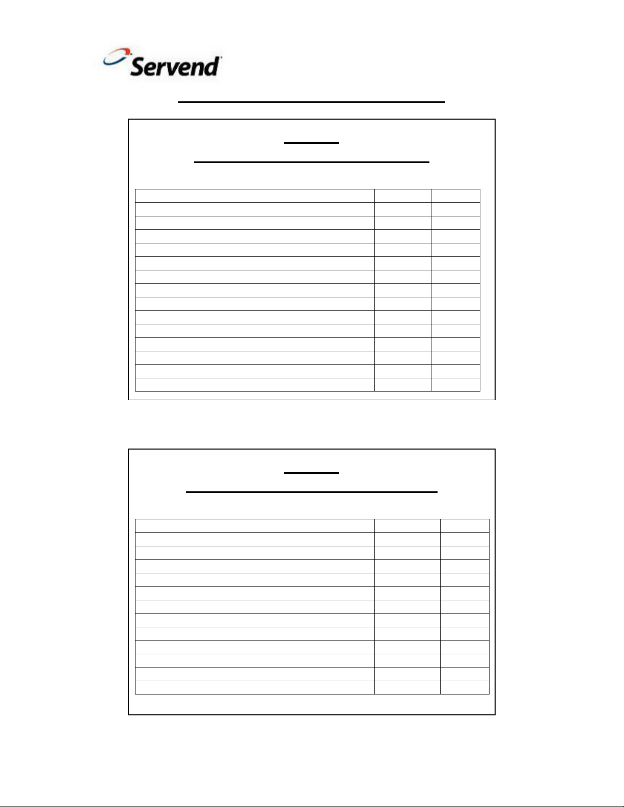
Parts Included in Kit No.: 5031536
8-32 Self Tapping Countersink Screw 0900504 1
8-32 Self Tapping Screw 5011940 1
No.8 Course Thread Screw 5013485 1
115 Volt 60Hz Wiring Diagram Label 5029625 1
208-230 Volt 60Hz Wiring Diagram Label 5029626 1
220-240 Volt 50Hz Wiring Diagram Label 5029627 1
Key Switch Bracket 5031050 1
Metal Bonnet Assembly 5031537 1
Splash Panel 5031538 1
Condenser Bracket Assembly 5031539 1
Installation Instructions 5031540 1
Beverage Configuration Label (STD) 5012519 1
Beverage Configuration Label (Juice) 5013734 1
Beverage Configuration Label (5 VLV) 5027794 1
Beverage Configuration Label (Var VLV) 020001226 1
Description Part Number Qty
Parts Included in Kit No.: 020002844
8-32 Self Tapping Countersink Screw 0900504 1
8-32 Self Tapping Screw 5011940 1
No.8 Course Thread Screw 5013485 1
115 Volt 60Hz Wiring Diagram Label 5029625 1
208-230 Volt 60Hz Wiring Diagram Label 5029626 1
220-240 Volt 50Hz Wiring Diagram Label 5029627 1
Key Switch Bracket 5031050 1
Metal Bonnet Assembly 20002778 1
Splash Panel 020002829 1
Condenser Bracket Assembly 5031539 1
Installation Instructions 5031540 1
Beverage Configuration Label (STD) 5013361 1
Beverage Configuration Label (Var VLV) 020002740 1
Description Part Number Qty
CEV30
CEV40
Part Number 5031540 Revision-1
Page 2
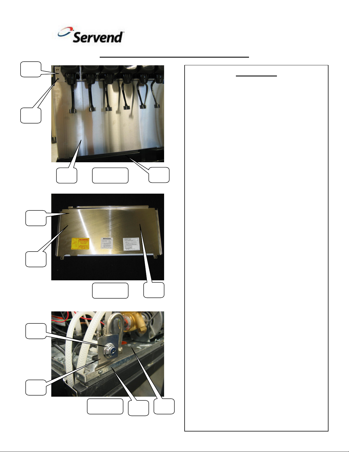
1A
1B
2A
2B
3A
3B
2 of 4
CEV Metal Bonnet Installation Instructions
Instructions
1) Disconnect or shut off power supply to
CEV unit. Failure to do so may cause
electrical shock or injury.
2) Remove existing plastic merchandiser,
light kit, bonnet wrap and rear panel
assembly from existing unit. Remove
existing condenser air filter from rear
panel assembly. Clean air filter
1C
Figure 1
1D
Figure 2
2C
Figure 3
3D
3C
Part Number 5031540 Revision-1
thoroughly and retain for reuse. Review
service and install manual for further
removal details
3) Disconnect wires from valve key switch.
Remove both L-shape brackets on each
side of the valve mount cap (1A) by
removing the four 8-32 mounting screws
(two each side). Retain screws for reuse.
Remove existing key switch assembly
from L-shaped bracket by removing the
retaining nut. Retain key switch assembly
for reuse. Reinstall two of the four 8-32
mounting screws (1B) in bottom
mounting slots on left and right sides of
valve mount cap (See Figure 1).
4) Remove drain pan (1D) and the existing
splash panel (1C). Keep drain pan for
reuse and discard splash panel (See
Figure 1).
5) The new splash panel (2A) will require
the correct wiring diagram installed on
back upper left side (2B) and plumbing
diagram on back upper right side (2C) of
panel. All voltage option wiring diagrams
are provided along with all plumbing
diagrams. Review unit serial tag to
determine correct voltage wiring diagram
to be applied on new splash panel (See
Figure 2).
Page 3

5B
5C
6A
6B
3 of 4
CEV Metal Bonnet Installation Instructions
Instructions
4C
4B
Figure 4
4A
Figure 5
5A
Figure 6
6) Install new splash panel (1A) by
reinstalling the two 8-32 mounting
screws. Reinstall drain pan (1D) and
attach any drain lines that were
disconnected (See Figure 1).
7) Mount the key switch assembly (3A) to
new key switch bracket (3B) as shown.
Mount the key switch and bracket to
smaller deck plate (3C) located on top
right side of plastic tub. Use the existing
hole on smaller deck plate (3C) to mount
key switch and bracket with the provided
8-32 self tapping screw (3D). Connect
wires previously disconnected to the key
switch (See Figure 3).
8) Remove clear film on the adhesive tape
located on the back left side (4B) and
back right side (4C) of condenser bracket
assembly (4A) (See Figure 4).
9) Center condenser bracket assembly (5A)
onto air cooled condenser (5B). The
bracket should be flush to the bottom
side of condenser bracket assembly (5A)
to top of air cooled condenser (5B). Press
condenser bracket assembly (5A) firmly
against air cooled condenser (5B) to
adhere adhesive tape. Install the provided
8-32 self tapping countersink screw (5C)
through slot in lower left corner of
condenser bracket assembly (5A) and
into hole in air cooled condenser (5B)
(See Figure 5).
10) Reinstall the condenser air filter (6A)
into the condenser bracket assembly (6B)
as shown (See Figure 6).
Part Number 5031540 Revision-1
Page 4

7B
7C
7D
4 of 4
CEV Metal Bonnet Installation Instructions
Instructions
7A
Figure 7
11) Assemble the metal bonnet assembly
(7A) onto CEV unit. The metal bonnet
assembly (7A) needs to sit flush on the
top cosmetic trim area (7B) of plastic tub
and over top of valve mount cap. Align
the mounting slots located on front
bottom left and right side of metal bonnet
assembly (7A) with top mounting slots of
valve mount cap. Reinstall the two 8-32
mounting screws (7C) through slots of
the metal bonnet assembly and valve
mount cap. Install the provided No.8
course thread screw through slot located
on top left side (7D) of metal bonnet
assembly (7A) and into speed-clip on top
of condenser bracket assembly (See
Figure 7).
12) Turn on or reconnect power supply to
CEV unit. Dispense drinks from unit to
ensure proper operation before placing
unit back into general service.
Part Number 5031540 Revision-1
 Loading...