

Page 1
BEVERAGE & FLAVOR
SHOT TOWERS
Installation, Use & Care Manual
This manual is updated as new information and models are released.
Visit our website for the latest manual. www.manitowocfsg.com
Leader in Ice & Beverage Dispensers
Part Number 5030763 5/11
Page 2
Safety Notices
! Warning
!
Caution
Important
!
Caution
Important
! Warning
As you work on Manitowoc equipment, be sure to pay
close attention to the safety notices in this manual.
Disregarding the notices may lead to serious injury and/
or damage to the equipment.
Throughout this manual, you will see the following types
of safety notices:
Text in a Warning box alerts you to a potential
personal injury situation. Be sure to read the
Warning statement before proceeding, and work
carefully.
Text in a Caution box alerts you to a situation in
which you could damage the equip ment. Be sure to
read the Caution statement before proceeding, and
work carefully.
Procedural Notices
As you work on Manitowoc equipment, be sure to read
the procedural notices in this manual. These notices
supply helpful information which may assist you as you
work.
Throughout this manual, you will see the following types
of procedural notices:
Read These Before Proceeding:
Proper installation, care and maintenance are
essential for maximum performance and trouble-free
operation of your Manitowoc equipment. Read and
understand this manual. It contains valuable care
and maintenance information. If you encounter
problems not covered by this manual, do not
proceed, contact Manitowoc Foodservice Group.
We will be happy to provide assistance.
Routine adjustments and maintenance procedures
outlined in this manual are not covered by the
warranty.
PERSONAL INJURY POTENTIAL
Do not operate equipment that has been misused,
abused, neglected, damaged, or altered/modified
from that of original manufactured specifications.
NOTE: SAVE THESE INSTRUCTIONS.
Text in an Important box provides you with
information that may help you perform a procedure
more efficiently. Disregarding this information will not
cause damage or injury, but it may slow you down as
you work.
NOTE: Text set off as a Note provides you with simple,
but useful, extra information about th e pr oce dur e yo u
are performing.
We reserve the right to make product improvements at any time.
Specifications and design are subject to change without notice.
Page 3

Section 1
General Information
Read This Manual. . . . . . . . . . . . . . . . . . . . . . . . . . . . . . . . . . . . . . . . . . . . . . . . . 1-1
Unit Inspection . . . . . . . . . . . . . . . . . . . . . . . . . . . . . . . . . . . . . . . . . . . . . . . . . . . 1-1
Model Numbers. . . . . . . . . . . . . . . . . . . . . . . . . . . . . . . . . . . . . . . . . . . . . . . . . . . 1-1
How to Read a Model Number. . . . . . . . . . . . . . . . . . . . . . . . . . . . . . . . . . . . . . . 1-1
Serial Number Location . . . . . . . . . . . . . . . . . . . . . . . . . . . . . . . . . . . . . . . . . . . . 1-2
Warranty Information . . . . . . . . . . . . . . . . . . . . . . . . . . . . . . . . . . . . . . . . . . . . . . 1-2
Section 2
Installation Instructions
General . . . . . . . . . . . . . . . . . . . . . . . . . . . . . . . . . . . . . . . . . . . . . . . . . . . . . . . . . 2-1
Dimensions . . . . . . . . . . . . . . . . . . . . . . . . . . . . . . . . . . . . . . . . . . . . . . . . . . . . . . 2-1
Footprint . . . . . . . . . . . . . . . . . . . . . . . . . . . . . . . . . . . . . . . . . . . . . . . . . . . . . . . . 2-2
Location. . . . . . . . . . . . . . . . . . . . . . . . . . . . . . . . . . . . . . . . . . . . . . . . . . . . . . . . . 2-3
Pre-installation Checklist. . . . . . . . . . . . . . . . . . . . . . . . . . . . . . . . . . . . . . . . . . . 2-3
Electrical . . . . . . . . . . . . . . . . . . . . . . . . . . . . . . . . . . . . . . . . . . . . . . . . . . . . . . . . 2-4
Wat er Supply. . . . . . . . . . . . . . . . . . . . . . . . . . . . . . . . . . . . . . . . . . . . . . . . . . . . . 2-5
Step by Step Installation . . . . . . . . . . . . . . . . . . . . . . . . . . . . . . . . . . . . . . . . . . . 2-5
Table of Contents
General . . . . . . . . . . . . . . . . . . . . . . . . . . . . . . . . . . . . . . . . . . . . . . . . . . . . 2-4
Minimum Circuit Ampacity . . . . . . . . . . . . . . . . . . . . . . . . . . . . . . . . . . . . . 2-4
Electrical Requirements . . . . . . . . . . . . . . . . . . . . . . . . . . . . . . . . . . . . . . . 2-4
Minimum Circuit Amperage Chart . . . . . . . . . . . . . . . . . . . . . . . . . . . . . . . . 2-4
Grounding Instructions . . . . . . . . . . . . . . . . . . . . . . . . . . . . . . . . . . . . . . . . 2-4
Recommended Plumbing . . . . . . . . . . . . . . . . . . . . . . . . . . . . . . . . . . . . . . 2-5
Specifications Chart . . . . . . . . . . . . . . . . . . . . . . . . . . . . . . . . . . . . . . . . . . 2-5
Unit Installation . . . . . . . . . . . . . . . . . . . . . . . . . . . . . . . . . . . . . . . . . . . . . . 2-5
Pre-mix Pressures . . . . . . . . . . . . . . . . . . . . . . . . . . . . . . . . . . . . . . . . . . . 2-6
System Pressures . . . . . . . . . . . . . . . . . . . . . . . . . . . . . . . . . . . . . . . . . . . . 2-6
Part Number 5030763 5/11 i
Page 4

Section 3
Operation
Table of Contents (continued)
General System Overview . . . . . . . . . . . . . . . . . . . . . . . . . . . . . . . . . . . . . . . . . . 3-1
Starting Your Beverage System. . . . . . . . . . . . . . . . . . . . . . . . . . . . . . . . . . . . . . 3-1
Component Identification . . . . . . . . . . . . . . . . . . . . . . . . . . . . . . . . . . . . . . . . . . . 3-2
Sequence of Operation. . . . . . . . . . . . . . . . . . . . . . . . . . . . . . . . . . . . . . . . . . . . . 3-3
Beverage Valves . . . . . . . . . . . . . . . . . . . . . . . . . . . . . . . . . . . . . . . . . . . . . 3-3
Carbonation . . . . . . . . . . . . . . . . . . . . . . . . . . . . . . . . . . . . . . . . . . . . . . . . . 3-3
Syrup Delivery System . . . . . . . . . . . . . . . . . . . . . . . . . . . . . . . . . . . . . . . . 3-3
Back Room Package . . . . . . . . . . . . . . . . . . . . . . . . . . . . . . . . . . . . . . . . . . 3-3
Racking . . . . . . . . . . . . . . . . . . . . . . . . . . . . . . . . . . . . . . . . . . . . . . . . . . . . 3-4
B-I-B . . . . . . . . . . . . . . . . . . . . . . . . . . . . . . . . . . . . . . . . . . . . . . . . . . . . . . 3-4
Pumps . . . . . . . . . . . . . . . . . . . . . . . . . . . . . . . . . . . . . . . . . . . . . . . . . . . . . 3-4
Auto Bag Selectors . . . . . . . . . . . . . . . . . . . . . . . . . . . . . . . . . . . . . . . . . . . 3-4
Figal System . . . . . . . . . . . . . . . . . . . . . . . . . . . . . . . . . . . . . . . . . . . . . . . . 3-4
Figal Tanks . . . . . . . . . . . . . . . . . . . . . . . . . . . . . . . . . . . . . . . . . . . . . . . . . 3-4
Section 4
Maintenance
Cleaning. . . . . . . . . . . . . . . . . . . . . . . . . . . . . . . . . . . . . . . . . . . . . . . . . . . . . . . . . 4-1
Preventive Maintenance . . . . . . . . . . . . . . . . . . . . . . . . . . . . . . . . . . . . . . . . . . . . 4-2
Sanitizing . . . . . . . . . . . . . . . . . . . . . . . . . . . . . . . . . . . . . . . . . . . . . . . . . . . . . . . . 4-3
Shipping, Storage and Relocation. . . . . . . . . . . . . . . . . . . . . . . . . . . . . . . . . . . . 4-4
Section 5
Before Calling for Service
Checklist . . . . . . . . . . . . . . . . . . . . . . . . . . . . . . . . . . . . . . . . . . . . . . . . . . . . . . . . 5-1
Daily Cleaning . . . . . . . . . . . . . . . . . . . . . . . . . . . . . . . . . . . . . . . . . . . . . . . 4-1
MONTHLY SANITIZING . . . . . . . . . . . . . . . . . . . . . . . . . . . . . . . . . . . . . . . 4-1
Cleaning Checklist . . . . . . . . . . . . . . . . . . . . . . . . . . . . . . . . . . . . . . . . . . . . 4-2
Beverage System Cleaning . . . . . . . . . . . . . . . . . . . . . . . . . . . . . . . . . . . . . 4-3
Bag-In-Box System Sanitation . . . . . . . . . . . . . . . . . . . . . . . . . . . . . . . . . . . 4-3
Figal Beverage System . . . . . . . . . . . . . . . . . . . . . . . . . . . . . . . . . . . . . . . . 4-4
Drink Troubleshooting . . . . . . . . . . . . . . . . . . . . . . . . . . . . . . . . . . . . . . . . . 5-1
ii Part Number 5030763 5/11
Page 5
Section 1
!
Warning
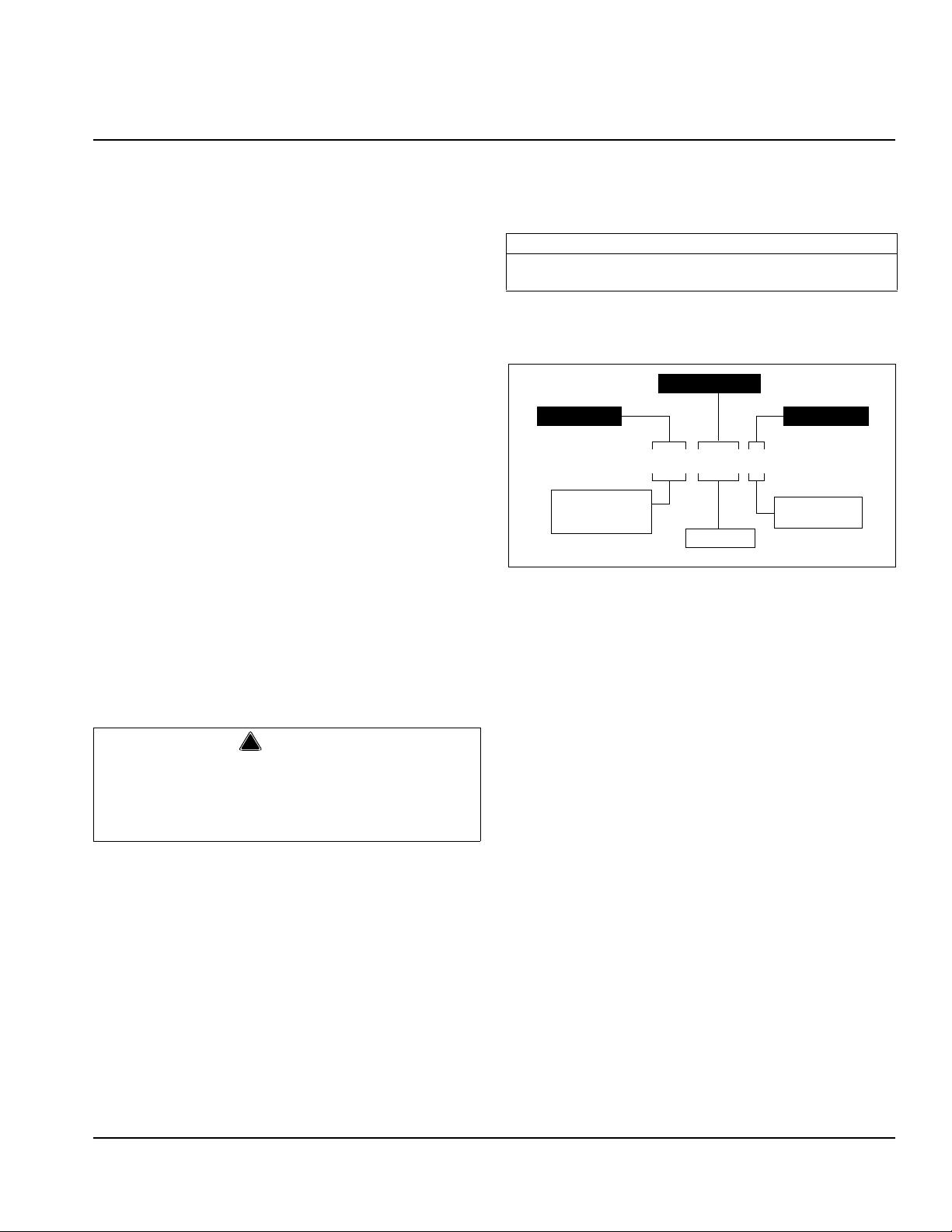
S - Ice Dispenser
SV - Ice/Beverage
Dispenser
i - intelli-carb
QD - quickdraw
Ice Capacity
Model Prefix Model Suffix
Model Base
SV–250–i
General Information
Read This Manual
Manitowoc Beverage Systems (MBS) developed this
manual as a reference guide for the owner/oper ator a nd
installer of this equipment. Please read this manual
before installation or operation of the machine. A
qualified service technician must perform inst allation and
start-up of this equipment, consult Section 5 within this
manual for service assistance.
If you cannot correct the service problem, call your MBS
Service Agent or Distributor. Always have your model
and serial number available when you call.
Your Service Agent ____________________________
Service Agent Telephone Number _________________
Your Local MBS Distributor ______________________
Distributor Telephone Number____________________
Model Number _______________________________
Serial Number ________________________________
Installation Date ______________________________
Unit Inspection
Thoroughly inspect the unit upon delivery. Immediately
report any damage that occurred during tr ansportation to
the delivery carrier. Request a written inspection report
from a claims inspector to document any necessary
claim.
Model Numbers
This manual covers the following models:
Beverage Dispensers
Model 2P FS, 464 Tower, Bev Tower, 2703405,
2703406, 2703406, 2703329
How to Read a Model Number
PERSONAL INJURY POTENTIAL
Do not operate equipment that has been misused,
abused, neglected, damaged, or altered/modified
from that of original manufactured specifications.
Part Number 5030763 5/11 1-1
Page 6
General Information Section 1
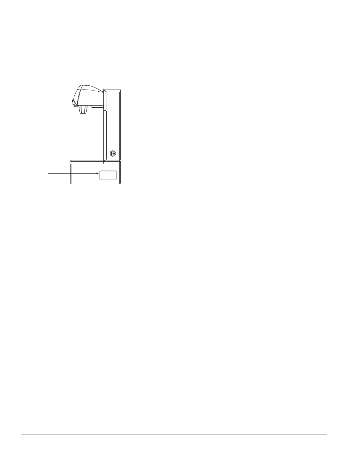
Label
Serial Number Location
This number is required when requesting information
from your local distributor. The serial number is listed on
the SERIAL NUMBER DECAL affixed to the dispenser.
Serial Number Location
Warranty Information
Consult your local MBE Distributor for terms and
conditions of your warranty. Your warranty specifically
excludes all beverage valve brixing, general
adjustments, cleaning, accessories and related
servicing.
Your warranty card must be returned to MBE to activate
the warranty on this equipment. If a warranty card is not
returned, the warranty period can begin when the
equipment leaves the MBE factory.
No equipment may be returned to MBE without a written
Return Materials Authorization (RMA). Equipment
returned without an RMA will be refused at MBE’s dock
and returned to the sender at the sender’s expense.
Please contact your local MBE distributor for return
procedures.
1-2
Part Number 5030763 5/11
Page 7
General
Important
Section 2
Installation Instructions
These instructions are provided to assist the qualified
installer. Contact your Manitowoc Beverage Equipment
Service Agent or call Manitowoc Beverage Equipment
for information regarding start-up service s.
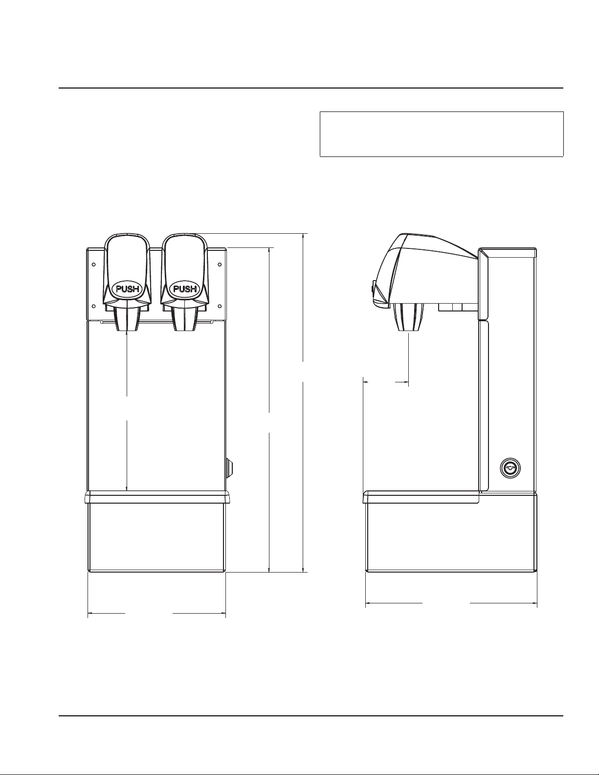
Dimensions
44.958 cm
8.375"
21.27 cm
16.875"
42.86 cm
17.70"
Failure to follow these installation guidelines may
affect warranty coverage.
2.375"
6.032 cm
8.9375"
7.1875"
18.23 cm
22.70 cm
Part Number 5030763 5/11 2-1
Page 8
Installation Instructions Section 2
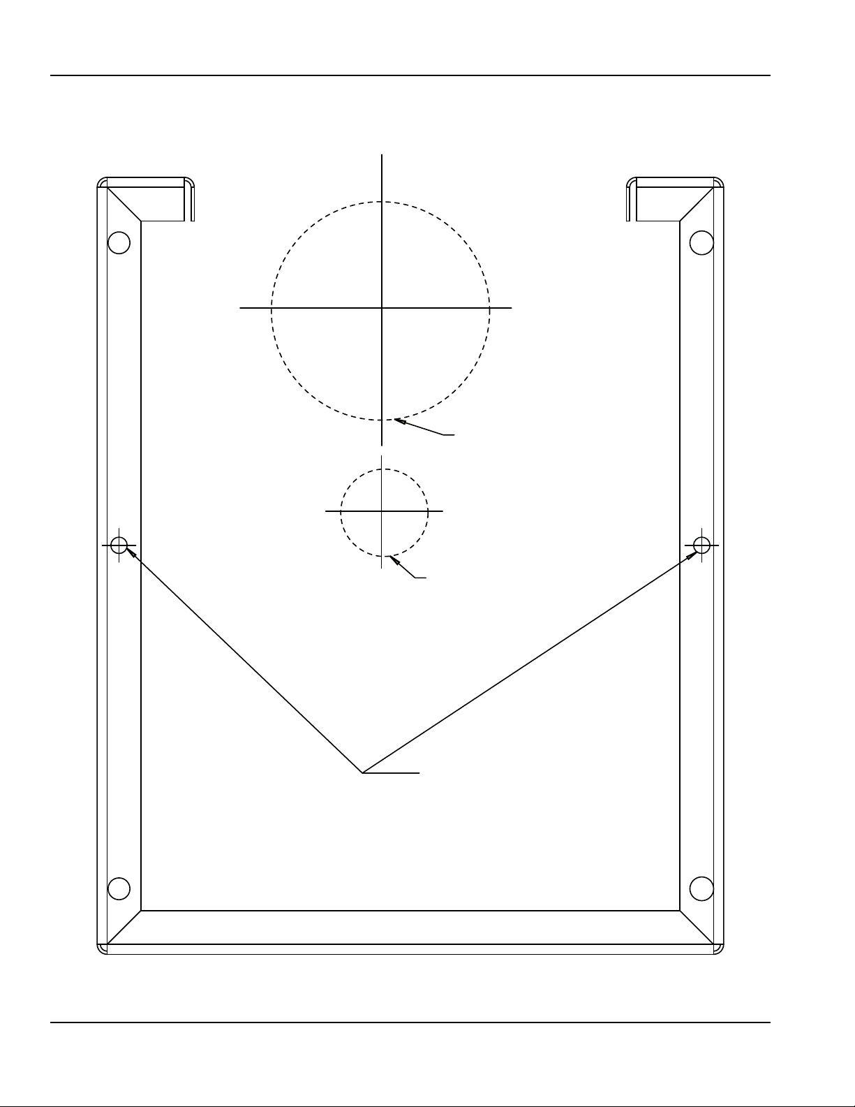
*OPTIONAL*
2.5" Ø CUT OUT FOR SYRUP LINES
*OPTIONAL*
1 1/4" Ø CUT OUT FOR DRAIN LINE
*OPTIONAL*
3/16" ØHOLES FOR MOUNTING SCREWS
Footprint
2-2
Part Number 5030763 5/11
Page 9

Section 2 Installation Instructions
!
Warning
Location
The location selected for the beverage dispenser must
meet the following criteria. If any of these criteria are not
met, select another location.
• The air temperature must be at least 50°F (10°C), but
must not exceed 95°F (35°C).
• The location must not be near heat-generating
equipment or in direct sunlight and must be protected
from weather.
• The countertop must be level. Verify that the
countertop can support the weight of the dispe ns er.
• Water lines, drains and power outlet must be within 6'
(1.8 m) of location.
Carbon Dioxide (CO2) displaces oxygen. Exposure
to a high concentration of CO
which are followed rapidly by loss of con sciousness
and suffocation. If a CO
particularly in a small area, immediately ventilate the
area before repairing the leak. CO
must not be installed in an enclosed space. An
enclosed space can be a cooler or small room or
closet. This may include convenience stores with
glass door self serve coolers. If you suspect CO
may build up in an area, venting of the B-I-B pumps
and / or CO
monitors must be utilized.
2
gas causes tremors,
2
gas leak is suspected,
2
lines and pumps
2
2
Stepless (Oetiker) clamps
Chain for CO
B-I-B System also:
B-I-B connectors
B-I-B regulator set
B-I-B rack
B-I-B syrup boxes
Post Mix System:
CO
regulator set
2
Beverage dispenser
Beverage tubing
tank
CO
2
tank
2
Pre-installation Checklist
When installing any system, first make sure the major
components are available. Generally the major
components necessary for an installation are:
Pre-mix System:
regulator set
CO
2
Product connectors for Figal tank
Gas connectors for Figal tank
Beverage dispenser
Beverage tubing
tank
CO
2
Figal beverage tanks
Carbonator
Stepless (Oetiker) clamps
Chain for CO
tank
2
Bulk Syrup System also:
Syrup connectors for Bulk tank
Gas connectors for Bulk tank
Bulk syrup tanks
Part Number 5030763 5/11 2-3
Page 10

Installation Instructions Section 2
!
Warning
Important
!
Warning
!
Warning
!
Warning
Electrical
GENERAL
Improper connection of the equipment-grounding
conductor can result in a risk of electric shock. The
All wiring must conform to local, state and national
codes.
MINIMUM CIRCUIT AMPACITY
The minimum circuit ampacity is used to help select the
wire size of the electrical supply. (Minimum circuit
ampacity is not the beverage/ice machine’s running amp
load.) The wire size (or gauge) is also dependent upon
location, materials used, length of run, etc., so it must be
determined by a qualified electrician.
ELECTRICAL REQUIREMENTS
Refer to Ice Machine Model/Serial Plate for
voltage/amperage specifications.
MINIMUM CIRCUIT AMPERAGE CHART
Due to continuous improvements, this information is
for reference only. Please refer to the dispenser
serial number tag to verify electrical data. Serial tag
information overrides information listed on this page.
Dispenser Voltage Amps
Beverage Tower,
Model 2P FS,
464 Tower
GROUNDING INSTRUCTIONS
The beverage/ice machine must be grounded in
accordance with national and local electrical codes.
This appliance must be grounded. In the event of
malfunction or breakdown, grounding provides a path of
least resistance for electric current to reduce the risk of
electric shock. This appliance is equipped with a cord
having an equipment-grounding conductor and a
grounding plug. The plug must be plugged into an
appropriate outlet that is properly inst alled and grounded
in accordance with all local codes and ordinances.
24V AC 2.4
(Remote Mount)
conductor with insulation having an outer surface that is
green with or without yellow stripes is the equipment
grounding conductor. If repair or replacement of the cord or
plug is necessary, do not connect the equipmentgrounding conductor to a live terminal. Check with a
qualified electrician or serviceman if the grounding
instructions are not completely understood, or if in doubt as
to whether the appliance is properly grounded. Do not
modify the plug provided with the appliance — if it will not fit
the outlet, have a proper outlet installed by a qualified
electrician.
When using electric appliances, basic precautions must
always be followed, including the following:
a. Read all the instructions before using the appliance.
b. T o reduce the risk of injury, close supervision is
necessary when an appliance is used near children.
c. Do not contact moving parts.
d. Only use attachments recommended or sold by the
manufacturer.
e. Do not use outdoors.
f. For a cord-connected appliance, the following shall
be included:
• Do not unplug by pulling on cord. T o unplug,
grasp the plug, not the cord.
• Unplug from outlet when not in use and before
servicing or cleaning.
• Do not operate any appliance with a damaged
cord or plug, or after the appliance malfunctions or
is dropped or damaged in any manner . Contact
the nearest authorized service facility for
examination, repair , or electrical or mechanical
adjustment.
g. For a permanently connected appliance — Turn the
power switch to the off position when the appliance is
not in use and before servicing or cleaning.
h. For an appliance with a replaceable lamp — Always
unplug before replacing the lamp. Replace the bulb
with the same type.
i. For a grounded appliance — Connect to a properly
grounded outlet only . See Grounding Instructions.
2-4
Part Number 5030763 5/11
Page 11

Section 2 Installation Instructions
Important
Drain Fitting
Drain Pan
Water Supply
RECOMMENDED PLUMBING
The plumbing diagram is printed on a white vinyl label,
located above the inlet tubes for syrup and water. The
plumbing diagram label can be accessed by removing
the splash panel of the dispenser . The plumbing diagram
label explains which inlet coldplate fittings supply which
dispenser valves and water manifolds.
The water supply must first be connected to the
carbonator pump (not shown) before plumbing to
connection “A” shown on plumbing diagram. The
carbonator pump deck must be within six feet of the
dispenser for optimum performance. See BIB inst allation
diagram for system pressure settings.
When installing cold carbonated (Intelli carb)
equipment, never put a tee for the plain water
connection in the line from the pump deck to the
cold plate. Putting a tee in the line will create service
problems and bad drink quality.
UNIT INSTALLATION
1. Carefully remove the tower from the shipping container
and check for freight damage. Any damage should be
noted at the time of delivery and reported to the carrier .
NOTE: DO NOT DISCARD ACCESSORIES BAG .
2. Select the tower location.
3. Using the enclosed template (P.N. 5012434), mark cut
outs for syrup/water lines, drain line (if used) and
mounting screws.
4. Cut the holes for the incoming water, syrup, and (if used)
drain lines.
5. Drain line:
NOTE: Valves are read from right to left.
A check valve must be installed in the water supply line
3 feet from the noncarbonated water connection “PW”.
Contact factory if not installed.
Step by Step Installation
SPECIFICATIONS CHART
Min. Max
Water pressure 40 psi 55 psi
Ambient temperature 40°F
(4°C)
CO2 pressure 40 psi 50 psi
Electrical 24VAC
Pre-mix pressure
Normal 60 psi*
Diet 40 psi*
B-I-B 60 psi or according to line run
* This is the optimal pressure. When the foam is too high, decrease
the pressure; when spitting/popping is an issue, increase the
pressure.
105°F
(41°C)
A. If a drain line is desired, carefully remove end from
3/4” (1.905 cm) horizontal drain fitting (See Above )
on drain pan and attach a 3/4” (1.905 cm) insulate d
drain line of sufficient length to reach drain. Assure
that drain line slopes toward drain 1/8” per foot
(0.5cm per m) or per local plumbing codes.
B. If no drain line is desired, DO NOT remove end of
3/4” (1.905 cm) drain fitting. Drain pan will have to
be removed and emptied manually as required.
6. Plumb the tower.
A. Plumb the syrup lines using the two (2) pre plumbed
tower syrup line connections with 1/4”(.635cm) by
3/8“(.95cm) connectors to 3/8“(.95cm) syrup line.
B. Attach syrup lines to syrup connection on syrup
pump.
C. Plumb the water/soda line using the 1/4”(.635cm)
pre plumbed tower water line connection with
1/4”(.635cm) X 3/8“(.95cm) connector to a
3/8“(.95cm) water line.
NOTE: No water line connection is used on Flavor Shot T owers.
D. Attach water line to water source, carbonated water
or plain water as required.
Part Number 5030763 5/11 2-5
Page 12

Installation Instructions Section 2
Important
7. Mount the tower and secure with the two (2) enclosed
#8 X 3/4” (1.905 cm) screws.
8. Plug the transformer butt connector into the tower .
9. Plug the transformer wall plug into a standard duplex
outlet.
10. Set syrup pump pressure on regulator according to line
run length and syrup viscosity .
1 1. T urn on water flow to valves.
12. Turn key to “ON” position.
13. Set the valve flow rates to between 1.5 oz (44 cc) /
second and 3.0 oz (88 cm) / second and brix the
beverage valves to the proper ratio after attainin g
normal beverage dispense temperature. For Flavor
Shot Towers set the syrup flow rate to 1 oz (30 cc)
/second and test run the valves.
14. Check for water and syrup leaks.
PRE-MIX PRESSURES
Normal pre-mix pressure regulators must be set at 60PSI.
Diet pre-mix pressure regulators must be set at 40 PSI. If
you are experiencing high foaming, decreasing the
pressures may correct the problem. Spitting and popping
usually requires slightly increasing the pressures. Pre-mix
beverage valve pressures vary by type and manufacturer .
Please consult the manufacturer of the valves you are using
for specific instructions regarding operation of the valve.
SYSTEM PRESSURES
1. Incoming tap water - must be at a minimum dynamic
pressure of 40 psi and maximum static pressure of 55
psi (measured at inlet to pump).
2. BIB pressure gauge must be set for 60 psi or according
to your line run.
3. Carbonator Pressure gauge (Use Preset Regulator):
- Cold Carbonation set for 75 psi.
- Ambient systems must be set at 90 psi to 105 psi.
If incoming water pressure is under 40 psi, a water
booster is recommended. If incoming water pressure is
over 55 psi, a water regulating valve is required.
2-6
Part Number 5030763 5/11
Page 13

General System Overview
90-
1800
60
105
Beverage Tower
Counter Top
Syrup
Tap Water
Tap Water
CO
2
Carbonated
Water
CO
2
Cylinder
CO
2
BIB Syrup
Pump
Syrup
Syrup
Non-carbonated
Water
Carbonator Tank
Bag-in-box
Syrup
Carton
Syrup
CO
2
Section 3
Operation
Typical External Carbonation (Ambient) Beverage Tower System
Starting Your Beverage System
Upon completion of the beverage dispenser and / or system
installation, all tubing, dispenser , an d system components
must be cleaned and sanitized prior to use.
NOTE: At installation equipment, dispensers, and tubing get
moved through many environments, dirt, dust, ch ases,
insulation, drywall, etc. It is an important procedure and best
practice to address cleaning to deliver the best quality drink
to your customer .
Part Number 5030763 5/11 3-1
Clean and sanitize the water and syrup circuits according to
instructions provided in this manual. Clean and sanitize the
dispenser components according to instructions provided in
this manual. Seal to counter top when no legs are used with
the unit. Consult and use local health codes if a discr epancy
occurs between this manual and your local health codes.
Page 14

Operation Section 3
Valve nozzle and diffusers
Soda or Flavor Shot Valves
Key Switch
Drainpan Grid
Drain Pan
Splash Panel
Component Identification
3-2
Part Number 5030763 5/11
Page 15

Section 3 Operation
From Water Supply
To Noncarbonated
Water Inlet Barb
Water to
Carbonator
Pump
Filter
Water Regulator
40–55 PSI
Booster System
(If Required)
To CO
2
Manifold (BIB
Pumps) from
CO
2
Supply
60 PSI
T o Syrup Inlet
Barbs on Unit
T o BIB Pumps
from BIB
To BIB
Pump
BIB
Sequence of Operation
BEVERAGE VALVES
Post-mix beverage valves are designed to precisely
meter the flow of both water and syrup to obtain the
proper mixing ratio. The syrup and soda w ate r
components of the post-mix beverage a re mixed as th ey
almost limitless. Check the temperatures expected for
the storage location. Adverse temperatures can affect
the storage and quality of beverage products. It is
recommended the temperature of storage location must
not fall below 40°F (4°C) or rise above 90°F (32°C).
BACK ROOM PACKAGE
leave the beverage valve.
CARBONATION
The purpose of the carbonator is to take regular tap
water at street water pressure (minimum 20 PSI,
maximum 80 PSI, dynamic or flowing pressure) 1/2"
water line and increase the water to beverage system
pressure (usually 100 PSI). This water is then combined
with the CO
same pressure, the CO
gas. Because the water and gas are at the
2
will dissolve into the water.
2
Chilling the mixture before dispensing will assist in
locking the carbon dioxide into the water. After
dispensing, the CO
The CO
will gradually leave the liquid due to pressure
2
may be unlocked from the liquid.
2
and temperature changes.
Components
The components of the carbonator are: water pump, an
electric motor to operate the pump, carbonator tank
where the water and CO
mix, and a water level control.
2
Operation
Carbon Dioxide (CO
) leaves the storage tank and
2
arrives at the carbonator tank through the gas inlet.
Water supply enters the carbonator pum p inlet at regular
street water line pressure (minimum 20 PSI, maximum
80 PSI, dynamic or flowing pressure). The water pump
increases the pressure of the water, which allows the
water to flow into the carbonator tank. The CO
and the
2
water mix together in the carbonator to produce the
carbonated water that is then sent to the soda dispenser.
The agitation of the water and CO
together in the tank
2
under high pressure creates the soda water. The quality
of carbonation (percent of CO
mixed in the water)
2
increases as the water temperature decreases and
exposure time increases.
The water level in the carbonator tank is controlled by a
water level control in the tank. This control turns the
pump motor off and on to maintain a preset level of liquid
in the tank. The water level control may be electronic
probes or a mechanical float.
SYRUP DELIVERY SYSTEM
Your syrup location can vary depending on the volume
of beverages served and ease of accessibility. Your
beverage system may set in a back storage room or
under the counter of the dispenser. Configurations are
Part Number 5030763 5/11 3-3
1. Incoming tap water – mu st be at a minimum
dynamic pressure of 40 psi and maximum static
pressure of 55 psi.
2. Carbonator Water pump motor – Powers the
water pump. The water pump motor is part of the
carbonator pump deck.
3. Carbonator Water pump – Pumps tap water into
the carbonator tank. The water pump is part of the
carbonator. The incoming water for the carbonator
must be first run through the pump before
connecting to the proper cold plate inlet.
4. Internal/External Carbonator tank – Combines
CO
gas and tap water to form carbonated water.
2
The “carbonator” is the carbonator tank, water pump
and water pump motor.
Page 16

Operation Section 3
Carbonated Water to Dispenser
3/8 Syrup Lines to Dispenser
Incoming
Water
Carbonator
100 psi
CO
2
Soda Water
Pump
5. CO2 cylinder – Holds highly pressurized carbon dioxide
(CO
). The CO2 cylinder is a steel or aluminum cylinder
2
tank. CO
gas flows through the primary pressure
2
regulator.
6. BIB pressure gauge – Set for a minimum of 60 psi.
Indicates CO
7. Primary pressure regulator – Lowers the CO
pressure, to 100 psi, so the CO
pressure going to B-I-B pumps.
2
gas will be at the
2
gas
2
proper pressure to enter the carbonator regulator.
8. Lowered outgoing pressure – Set for 75 psi. Gauge
indicates lowered outgoing pressure from the CO
2
cylinder after being routed through the primary pressur e
regulator at 100 psi.
9. Secondary pressure regulator – Lowers the CO
pressure before the CO
CO
pressure activates the syrup pump.
2
gas flows to the syrup pump.
2
gas
2
10. Syrup pump – Draws syrup out of the bag-in-box syrup
package. Syrup flows through the syrup lines to the
dispenser for chilling, then dispensing. There is a syrup
pump for each bag-in-box syrup system.
11. Bag-In-Box syrup cartons – Box which contains a
plastic bag, filled with syrup.
RACKING
Regardless if you are working on a B-I-B or Figal system, a
place will be designated for placement of the product. A rack
(or shelf) system affords systematic placement and
complete usage of the beverage paid for. The B-I-B rack
allows the boxes to lay properly for syrup dispersal. Please
check with your B-I-B syrup supplier. Some boxes must be
slightly tilted down, while others may be in virtually any
position. The Figal tank rack keeps the newer and full tanks
organized at one end of the beverage line with the partial
tanks at the other .
B-I-B
The Bag-In-Box system refers to a plastic disposable bag.
The B-I-B normally contains 5 gallons of syrup, however
some locations offer 2-1/2 gallon B-I-B unit s. This plastic bag
is then held inside a cardboard or other container. B-I-B
systems are for post-mix applications only .
PUMPS
The syrup in a B-I-B system is delivered to the beverage
system through gas operated pumps. These pumps extract the
syrup out of the bags, forcing the syrup throughout the system.
AUTO BAG SELECTORS
These are used on higher volume B-I-B systems where two
or more bags of the same product are connected to one
pump and one system. An auto bag selector is essentially a
valve that automatically changes from one bag (or series of
bags) to another bag (or series of bags) of syru p as the bags
empty, allowing a constant flow of product.
FIGAL SYSTEM
Figal refers to the stainless steel tanks of pre-mix beverag e
or post-mix syrup. A small CO
tank pushes the beverage
2
out of the figal tank.
FIGAL T ANKS
The stainless steel Figal beverage tanks are easy to store
and connect. When using the Figal tanks:
• Use a gas connector for the inlet fitting of the tank.
• Use a syrup connector for the outlet fitting of the tank.
• If more than one Figal tank is connected in series, when
changing tanks, remove the tank closest to the original
gas inlet while adding the new tank to the conne ctor
closest to the syrup outlet.
Most Figal tanks have a self-closing valve on the tank as well
as the gas and syrup connectors. This allows the operator of
the system to change tanks without having to shut down the
entire system. With this type of connector , push down on the
connector while pulling up on the snap ring around the
opening of the connector . Then simply pull the connector of f
the tank.
3-4
Part Number 5030763 5/11
Page 17

Section 4
!
Caution
!
Warning
!
Warning
Valve Nozzle &
Diffusers
Soda or Flavor
Shot Valves
Drain Pan
Grid
Drain Pan
Splash
Panel
Maintenance
Cleaning
DAILY CLEANING
All cleaning must meet your local health department
regulations. The following cleaning instructions are
provided as a guide.
Y ou will need clean warm water to wash and rinse with, mild
non-abrasive soap and a clean cloth to cle an the following:
•Drain pan
•Grid
• Splash panel
• Valve nozzles
• Diffusers
1. Lift up the grid and remove it fro m the drain p an.
2. Using mild soap, warm water and clean cloth, wash the
drain pan and splash panel. Then rinse with clean,
warm water. Allo w plenty of warm water to r un down the
drain to remove syrup residue that can clog the drain
opening.
3. Wash the grid, then rinse with clean warm water .
4. Place the grid back in the drain pan.
Use only warm soapy water to clean the exterior of the
tower. Do not use solvents or other cleaning agent s. Do
not pour hot coffee into the drain pan. Pouring hot
coffee down the drain pan can eventually crack the
drain pan, especially if the drain pan is cold or still
contains ice.
Electric Shock Hazard
Unplug unit before servicing or cleaning.
When using cleaning fluids or chemicals, rubber
gloves and eye protection must be wor n.
5. Wash all exterior surfaces of the unit with warm water
and a clean cloth. Wipe again with a clean, dry cloth.
6. For Flomatic Valves, tur n nozzle and pull the downward
to remove.
7. Clean both the nozzle and diffuser with soap and water
to remove syrup residue. (A soft bristle brush can be
used).
8. Rinse nozzle and diffuser with warm, clean water .
9. Replace diffuser in the valve body . Position nozzle and
turn counter clockwise to the stop.
MONTHL Y SANITIZING
Mix a sanitizing solution of 1/2 ounce liquid, unscented
bleach (5.25%Cl Na O concentration) with a gallon of water ,
to supply 100 PPM of available chlorine. Using this solution
and a clean cloth or soft bristle brush, sanitize the parts
mentioned in the daily cleaning procedure. Allow part s to air
dry and then re-assemble.
Part Number 5030763 5/11 4-1
Page 18

Maintenance Section 4
CLEANING CHECKLIST
•Check CO
the primary regulator gauge will point to a shaded
area that reads “Low CO
Cylinder.”
• Check syrup supply.
• Clean drain pan, grid, and splash panel.
• Clean the valve nozzles and diffusers.
supply. If CO2 supply is low, an arrow on
2
” or “Change CO2
2
Preventive Maintenance
Preventative maintenance is a vital part of keeping your
dispenser in top condition. Following the guidelines
below will assist you in continued trouble-free operation
of your unit.
1. Conduct daily maintenance of the machine.
2. Perform monthly maintenance of the machine.
3. Perform periodic maintenance and sanitizing of
beverage system.
4. Do not allow the dispenser to sit for prolonged
periods of non use.
4-2
Part Number 5030763 5/11
Page 19

Section 4 Maintenance
!
Warning
!
Warning
Bag
side
connector
Sanitizing
BEVERAGE SYSTEM CLEANING
Flush sanitizing solution from syrup system.
Residual sanitizing solution left in system could
create a health hazard.
When using cleaning fluids or chemicals, rubber
gloves and eye protection must be wor n.
Sanitize the beverage system at initial start-up as well as
regularly scheduled cleaning. The drain pan must be in
place under soda valves, to carry away detergent and
sanitizing agents that will be flushed through valves.
BAG-IN-BOX SYSTEM SANITATION
The procedure below is for the sanitation of one
syrup circuit at a time. Repeat to sanitize additional
circuits.
You will need the following items to clean and sanitize
the Bag-in-Box (BIB) beverage system:
• Three (3) clean buckets
2. Disconnect the “syrup-line side” of the bag-in-box
connector.
3. Rinse connector with warm tap water.
4. Connect syrup connector to BIB connector and
immerse both into Bucket 1. A “bag-side” connector
can be created by cutting the connector from an
empty disposable syrup bag.
• Plastic brush or soft cloth
• Mild detergent
• Unscented bleach (5% Na CL O) or
Commercial sanitizer
• Bag-In-Box bag connector
1. Prepare the following in the buckets:
• Bucket 1 — warm to hot tap water for rinsing.
• Bucket 2 — mild detergent and warm to hot
water.
• Bucket 3 — mix a solution of unscented bleach
(5% Na CL O) or commercial sanitizer and warm
to hot water. Mixture must supply 100 PPM
available chlorine (1/4 oz. bleach to 1 gallon
water).
Part Number 5030763 5/11 4-3
Page 20

Maintenance Section 4
!
Caution
5. Draw rinse water through system until clean water is
dispensed. Most beverage valves allow the syrup
side to be manually activated by depressing the
syrup pallet.
6. Connect Bucket 2 to system.
7. Draw detergent solution through system until
solution is dispensed.
8. Repeat steps 2-7 until all syrup circuits contain
detergent solution.
9. Allow detergent solution to remain in the system for
5 minutes.
10. Connect Bucket 3 to system.
11. Draw sanitizing solution through system until
solution is dispensed.
12. Repeat step 11 until all syr up circuits contain
sanitizer solution.
13. Allow sanitizer solution to remain in system for 15
minutes.
14. Remove nozzles and diffusers from beverage
valves.
15. Scrub nozzles, diffusers and all removable valve
parts (except electrical parts) with a plastic brush or
a soft cloth and the detergent solution.
16. Soak nozzles, diffusers and removable valve parts
(except electrical parts) in sanitizer for 15 minutes.
17. Replace nozzles, diffusers and valve parts.
18. Connect Bucket 1 to system.
19. Draw rinse water through system until no presence
of sanitizer is detected.
20. Attach syrup connectors to BIBs.
21. Draw syrup through system until only syrup is
dispensed.
22. Discard first 2 drinks.
2. Disconnect all product and water lines from product
tanks and remove carbonator.
3. Locate the Figal syrup tank for the circuit to be
sanitized. Remove both quick disconnects from the
Figal syrup tank. Rinse quick disconnects in tap
water.
4. Connect rinse tank to the syrup line. Draw clean
rinse water through the valve until syrup is flushed
from the system.
5. Connect detergent tank to the syrup line and draw
detergent through the valve for two minutes. Then,
allow remaining detergent to stay in the system for
five minutes.
6. Connect rinse tank to the syrup line. Draw clean
rinse water through the valve until detergent is
flushed from the system.
7. Remove valve nozzle and diffuser as shown in Daily
Cleaning instructions. Using a plastic brush or a soft
cloth and warm water , scrub the nozzle, diffuser,
bottom of the dispensing valve and cup lever, if
applicable.
8. Place removable valve parts (EXCEPT solenoids) in
sanitizing solution for 15 minutes.
9. Replace valve diffuser and nozzle on the beverage
valve.
10. Connect sanitizer tank to the syrup line and draw
sanitizer through the valve for two minutes. Allow
sanitizer to remain in the system for a minimum of
15 minutes.
11. Reconnect syrup and carbonated water lines.
12. Draw syrup through the lines to rinse the system.
Discard drinks until at least two cups of satisfactory
tasting beverage are dispensed through the valve.
Shipping, Storage and Relocation
FIGAL BEVERAGE SYSTEM
1. Prepare the following in three clean Figal tanks:
• Rinse tank - fill with room temperature tap water.
• Detergent tank - mix approved beverage
system cleaner with warm water as directed.
• Sanitizing tank - mix a solution of unscented
bleach (5% Na CL O) or commercial sanitizer
and warm to hot water. Mixture must supply 100
PPM available chlorine (1/4 oz. bleach to
1 gallon water).
4-4
Before shipping, storing, or relocating this unit,
syrup systems must be sanitized. After sanitizing, all
liquids (sanitizing solution and water) must be
purged from the unit. A freezing environment
causes residual sanitizing solution or water
remaining inside the unit to freeze, resulting in
damage to internal components.
Part Number 5030763 5/11
Page 21

Section 5
Before Calling for Service
Checklist
If a problem arises during operation of your dispenser, follow the checklist below before calling service. Routine
adjustments and maintenance procedures are not covered by the warranty.
DRINK TROUBLESHOOTING
Condition Investigation Check Correction
Water only dispensing No pressure Regulator(s) out of adjustment Check/adjust regulator(s).
Install fresh tank.
2
line pinched, kinked or
Install fresh tank.
2
line pinched, kinked or
pressure due to leaks Repair CO2 leaks.
2
Check/repair/replace CO2 line.
or reset breaker.
Replace water filter.
Check/clean/replace pump strainer.
Check/clean/repair water check valve.
Check for frozen water line. Internal
carbonator unit only.
motor, electrode or liquid level control.
Check/repair/replace CO2 line.
Adjust CO
Clean out the lines.
if necessary.
replace regulator if necessary.
pressure or change the tank.
2
pressure or replace regulator
2
supply. Reset pressure or
2
Syrup and CO
dispensing
Syrup and plain water
only dispensing
One valve will not
dispense anything
Beverage dispensed is
too sweet
Beverage is not sweet
enough
Drinks are foaming Are system pressures
No water, syrup or gas
dispensing
only
2
Carbonator No power Check power supply. Plug in carbonator
No pressure Out of CO
Is there power to the
valve?
Is the ratio (brix) of the
drink correct?
Is the ratio (brix) of the
drink correct?
correct?
Is there power to the
unit?
Is power coming
through the key
switch?
Is there power to the
key switch?
Out of CO
Defective regulator(s) Check/repair/replace regulator(s).
CO
2
obstructed
Water supply Make sure water is turned “on”.
Defective carbonator Check/repair/replace carbonator pump,
HP regulator out of adjustment Adjust HP regulator to the proper setting.
Defective HP regulator Check/repair/replace HP regulator.
CO
2
obstructed
Broken wire or loose connection Replace/repair wire or connector.
Bad microswitch Replace microswitch.
Flow control out of adjustment Adjust the flow control.
Insufficient soda flow due to low
carbonator pressure
Low CO
Obstruction in the water or soda
line
Flow control out of adjustment Adjust the flow control.
Soda flow too high Reset CO
Obstruction in syrup line Clean out the syrup line.
Over carbonation Check CO
Dirty lines/valves Clean/sanitize entire system.
No power Plug in unit or reset breaker.
Power to control box Replace fuse or control box.
Key switch “off” Turn switch “on”.
Key switch defective Replace key sw itch.
No power through the transformer Reset/replace transformer.
Part Number 5030763 5/11 5-1
Page 22

Before Calling for Service Section 5
THIS PAGE INTENTIONALLY LEFT BLANK
5-2
Part Number 5030763 5/11
Page 23

Page 24

© 2011 Manitowoc
Continuing product improvements
may necessitate change of
specifications without notice.
Part Number 5030763 5/11
Manitowoc Beverage Systems
Sellersburg, IN 47172, USA
Ph: 812-246-7000 Fax: 812-246-7024
Visit us online at: www.manitowocfsg.com
2100 Future Drive
 Loading...