

Page 1
Page 2

Contents
1. Welcome ............................................................................... 1
Welcome to DrawPlus ............................................................................. 2
New features ............................................................................................... 3
Installation ................................................................................................... 6
2. Getting Started ................................................................... 9
Startup Assistant .................................................................................... 10
Starting with a new drawing ............................................................. 13
Opening a drawing ............................................................................... 15
Saving your work ................................................................................... 17
Setting measurement units and drawing scale ......................... 18
Viewing pages ......................................................................................... 21
Adding and deleting pages ............................................................... 22
3. Lines, Curves, and Shapes .............................................23
Selecting one or more objects .......................................................... 24
Drawing lines and shapes ................................................................... 27
Drawing B-Spline curves ..................................................................... 32
Using QuickShapes ................................................................................ 37
Flooding areas ......................................................................................... 38
Editing lines and shapes ...................................................................... 42
Converting a shape to editable curves .......................................... 48
Adding dimension lines and labels ................................................. 49
Using the Gallery .................................................................................... 52
Page 3

Contents
4. Using Brushes and Text .................................................. 55
Applying brush strokes ........................................................................ 56
Pressure sensitivity ................................................................................ 58
Entering text ............................................................................................ 60
Editing text ............................................................................................... 62
Fitting text to a path ............................................................................. 63
5. Working with Objects ..................................................... 65
Copying, pasting, cutting, and deleting objects ....................... 66
Resizing objects ...................................................................................... 67
Replicating an object ............................................................................ 69
Rotating and shearing objects .......................................................... 73
Joining objects ........................................................................................ 75
Creating contours .................................................................................. 78
Grouping objects ................................................................................... 80
Aligning and distributing objects .................................................... 81
Ordering objects .................................................................................... 82
Working with layers .............................................................................. 83
Cutting up objects ................................................................................. 87
Erasing and adding to objects .......................................................... 89
6. Fills, Lines, Colours, and Transparency ..................... 91
Setting fill properties ............................................................................ 92
Setting line properties ......................................................................... 97
Sampling colours ................................................................................. 101
Working with gradient fills ............................................................... 102
Working with bitmap and plasma fills ......................................... 105
Working with vector fills ................................................................... 106
Setting opacity ...................................................................................... 107
Using transparency effects ............................................................... 110
Page 4

Contents
7. Pictures ............................................................................. 113
Importing pictures ............................................................................... 114
Using Cutout Studio ........................................................................... 115
Applying PhotoLab filters ................................................................. 118
Autotracing ............................................................................................ 121
8. Effects ................................................................................ 125
Using graphic styles ............................................................................ 126
Applying 2D filter effects .................................................................. 128
Applying 3D filter effects .................................................................. 129
Adding drop shadows ........................................................................ 131
Creating blends .................................................................................... 133
Using stencils ......................................................................................... 136
9. Stopframe/ Keyframe Animation ............................. 141
Getting started with animation ...................................................... 142
Working with Stopframe animation ............................................. 143
Working with Keyframe animation ............................................... 147
Exporting animations and presentations ................................... 151
10. Print, Publish and Share .............................................. 155
Interactive Print/PDF Preview ......................................................... 156
Printing basics ....................................................................................... 159
Publishing as PDF................................................................................. 161
Exporting objects and drawings .................................................... 163
Presentations with the Rostrum Camera .................................... 168
Page 5

Contents
11. Additional Information ............................................... 175
Contacting Serif .................................................................................... 176
Credits ...................................................................................................... 177
12. Index .................................................................................. 179
Page 6

Welcome
Page 7

2 Welcome
Welcome to DrawPlus
Welcome to DrawPlus X8—the design and illustration solution from
Serif, packed with all the features expected of award-winning design
software. From decorative page elements and logos to full-page
illustrations, scale drawings, multi-page folded publications, and
Stopframe or Keyframe animations—DrawPlus X8 does it all. With the
power of scalable vector graphics at your command, you'll see the
creative possibilities open up right before your eyes! Whether you're a
beginner or an expert, you'll find easy-to-use tools you can use right
away.
Upgrading
If you've upgraded from a previous version, this new edition of
DrawPlus includes a host of exciting new features which complement
DrawPlus's existing key features. We hope you also enjoy the additional
power and performance edge.
Registering
Don’t forget to register your new copy, using the Registration Wizard
on the Help menu. That way, we can keep you informed of new
developments and future upgrades!
Page 8

Welcome 3
New features
DrawPlus X8 (in 32 and 64-bit versions) introduces increased ease of
use, a host of new and improved features and tools—including one for
animating presentations, as well as photo and effect improvements, and
also enhanced importing and exporting options.
• High DPI support
Windows display scaling is supported with automatic selection of
suitably sized, sharp-looking buttons, controls and menus, so for
very high-resolution displays, displays at a distance, or for those
with impaired vision, DrawPlus X8 will look better than ever.
• Presentations with Rostrum Camera (see p. 168)
Show off your presentation, slideshow, or storyboard slide-byslide in an innovative and creative way using cool Rostrum
Camera panning, supporting slide transitions and progressive or
layer-by-layer reveals. Create from preset page layouts or base each
slide on drawn objects equally. Finally, export easily to Flash or
video using a range of presets.
Creative
• B-Spline curves (see p. 32)
As an alternative to drawing Bézier curves with the Pen Tool, try
the B-Spline Tool. Using a polygon framework, curve creation is
made simpler without the complexity of node and control handle
manipulation. Convert from B-spline curves to Bézier curves if
needed.
• Contours for cool tiered effects (see p. 78)
Shapes and text take on a stylish look with a multi-contour effect.
Copies of the original object are placed in front or behind the
original object; they incrementally scale and show with
decreasing/increasing greyscale levels. Contours can be
Page 9

4 Welcome
customized to control the number of contour steps and be placed
inside the object rather than outside.
• New and improved filter effects (see p. 128)
Add a new Trail effect, add ripple effects to reflections, apply a
cutoff setting for feathering, a directional/gradient feather, and an
outline and contoured line texture for variable-intensity drop
shadows.
• Replicate (see p. 70)
The new Replicate Tool creates copies of selected objects directly
on the page in repeating columns and rows, with controllable interobject spacing. At any time, return to the replicated objects to add
more or fewer objects.
• Flooding areas (see p. 38)
The Flood Tool is perfect for creating and colouring areas between
intersecting curves in your design as opposed to colouring an
object's line or fill. With this level of selective colouring, otherwise
restricted to objects, areas created by overlapping drawn curves or
by QuickShapes converted to curves can be coloured freely. These
coloured areas become closed shapes in their own right.
• Vector pattern fills (see p. 106)
The Swatch tab provides a new Vector pattern fill category which
hosts an impressive selection of brick, tile, dot, screen, line and
hatched patterns that output as vectors. Each fill can be customized
with respect to scaling, spacing, rotation and recolouring. You can
even create custom fills from drawn shapes or imported Serif
Metafiles.
Page 10

Ease of Use
• Feed-based Startup Assistant (see p. 10)
The new-look starting point for new drawings provides a wealth of
constantly updating cross-product news and DrawPlus-specific
learning resources (video tutorials, written tutorials, help, and
Tips & Tricks). The assistant keeps track of unread articles so you
won't miss a thing! An Open option also gives you access to all
your existing publications, based on document history.
• Restore Last Session (see p. 16)
On DrawPlus restart, optionally enable this feature to
automatically reopen previously opened drawings (view settings
and current page display are preserved too!) and start from where
you finished your last session.
• Smart sizing and rotating (see p. 68)
Multiple objects can be scaled or rotated proportionally with a
transformed selected object in your selection; individual objects
always retain their relative position on the page—great for charts
and plans! Shearing operations are also supported.
Welcome 5
Pictures
• New photo editing tools and effects (see p. 118)
Vibrance, Split Tone, Tilt Shift, and Clarity are new PhotoLab
filters that add fantastic effects to enhance pictures. Now control
vignette positioning and sizing. Blend effects smoothly across an
area using gradient masks, and remove unwanted blemishes,
clutter or imperfections with a clone brush.
Page 11
6 Welcome
• New scanning power (see DrawPlus Help)
As manufacturers have been very slow to introduce 64-bit scanning
software, DrawPlus has been updated to support 32-bit and any
newer 64-bit drivers, for both WIA and TWAIN driver types. Also
scan and place multiple images in one operation if your scanner
allows, without lifting the lid each time to swap pictures.
Installation
Installing DrawPlus follows different procedures depending on whether
you are installing from disc or via download.
You can install your new version alongside previous versions and
use them independently.
32 or 64-bit DrawPlus X8 installs to respective 32 or 64-bit
computers.
Installation procedure (from disc)
• Insert your purchased disc into your disc drive.
• If AutoPlay is enabled on the drive, this automatically starts the
Setup Wizard. Follow the on-screen instructions for install.
-or-
• If AutoPlay is not enabled (or doesn't start the install
automatically), navigate to your program disc and double-click
autorun.exe.
Page 12

Welcome 7
Installation procedure (from download)
• From serif.com, when logged into your Serif account, follow the
on-screen instructions to download.
System Requirements
Minimum:
• Windows-based PC* with mouse or equivalent input device
• Operating systems:
Windows® 8 (32 or 64 bit)
Windows® 7 (32 or 64 bit)
Windows® Vista (32 or 64 bit)
Windows® XP SP3 (32 bit)
• PC Memory:
512MB RAM (Windows® XP)
1GB RAM (Windows® Vista and 32-bit Windows 7® and 8)
2GB RAM (For 64-bit Windows® 7 and 8)
• Hard Drive Space:
665MB free hard disk space for physical media install (and a DVD
drive)
1GB free hard disk space for download install (additional space
required during installation)
• Screen Resolution:
1024 x 768 monitor resolution (at 100% scaling)
1280 x 960 monitor resolution (at 125% scaling)
1536 x 1152 monitor resolution (at 150% scaling)
2048 x 1536 monitor resolution (at 200% scaling)
Page 13

8 Welcome
• Other:
Internet account and connection for accessing online resources.
* Main processor must support SSE2 instructions. To enjoy the full
benefit of brushes and their textures, you must be using a computer
whose processor supports SSE (most modern computers do). On brush
selection, an on-screen message will indicate if your computer is nonSSE.
Additional disk resources and memory are required when editing large
or complex documents.
Recommended:
As above but:
• Dual-processor PC technology
Optional:
• Windows-compatible printer
• TWAIN-compatible scanner and/or digital camera
• Pressure-sensitive pen tablet
Page 14

Getting Started
Page 15
10 Getting Started
Startup Assistant
Once DrawPlus has been installed, you're ready to start.
• For Windows Vista/7: Setup adds a Serif DrawPlus X8 item to the
All Programs submenu of the Windows Start menu. Use the
Windows Start button to pop up the Start menu, click on All
Programs and then click Serif DrawPlus X8.
• For Windows 8: The Setup routine during install adds a Serif
DrawPlus X8 entry to the desktop and also to the Start screen.
Double-click the DrawPlus icon from the desktop, or click the
DrawPlus tile on the Start screen.
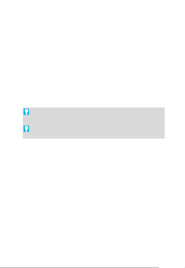
On program launch, the Startup Assistant is displayed which offers
different routes into DrawPlus:
Page 16
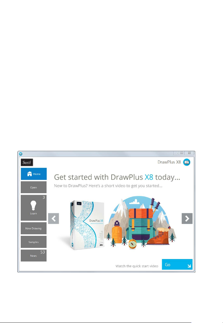
The options are described as follows:
The default home page provides access to
Provide document history, such as files you
Online videos and written tutorials, help, tips
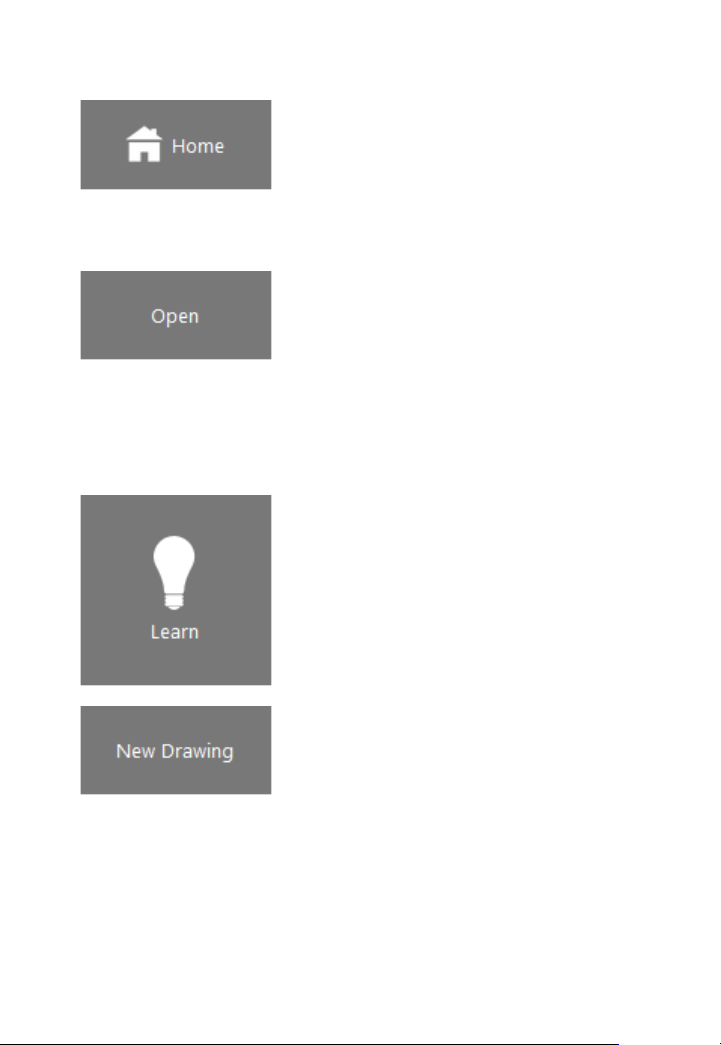
Create a New Drawing from scratch using a
Serif promotions and tutorial articles to get
you started with DrawPlus.
View the DrawPlus Overview or click Go to
see the Quick Start video.
have recently worked on including Restore
the Last Session which
drawing you created.
Browse your computer to access DrawPlus
files and picture files or create a design from
an existing PDF file.
& tricks, and more via an updating learn feed
that can be filtered by article Type.
The Product Help and your electronic
DrawPlus X8 user guide are also provided.
Getting Started 11
opens the most recent
simple setup.
Create a New Keyframe Animation.
Create a New Stopframe Animation.
Create a Custom drawing.
Page 17
12 Getting Started
Create an instant drawing from a predesigned sample.
For cross-product news, company news,
articles, and product announcements, using
Serif's news feed.
Use the keyword Search box to filter specific
file names, learn articles, samples, news or
articles.
Any time you access the Startup Assistant, the Learn or News buttons
indicate the number of new articles to be viewed (if available). This
number will decrease as you read each article in the Learn or News pane.
When new articles arrive, these will be indicated the next time you open
the Startup Assistant.
Any new unread article arriving in the Learn or News pane will
display a "new" indicator in its thumbnail.
Once you've clicked on a new article the "new" indicator
changes to a "read" indicator.
To access the Startup Assistant when DrawPlus is already running,
choose Startup Assistant from the File menu.
Page 18
Getting Started 13
Starting with a new drawing
The first time you launch DrawPlus, you'll see the Startup Assistant,
with a menu of choices.
The New Drawing option offers an easy way to create your new
drawing and lets you choose the initial setup for the particular type
of document you'll be producing.
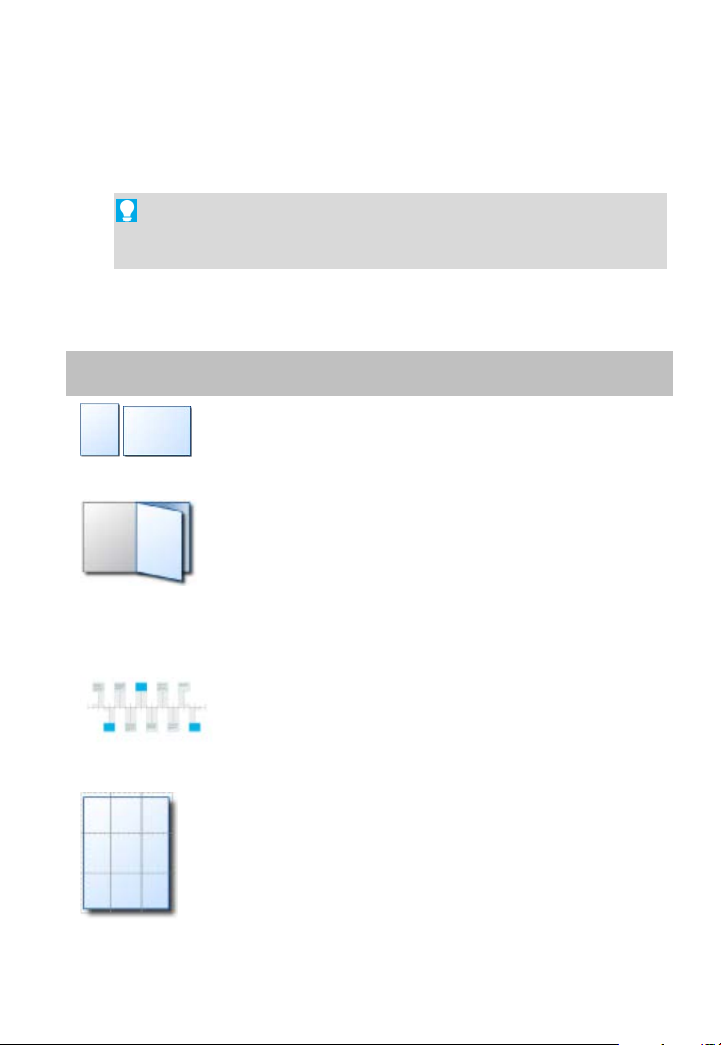
DrawPlus offers a wide range of preset document types from several
categories:
Category Document types
Portrait or landscape in all the commonly
Regular
Folded
Publications
encountered page sizes.
Greeting cards, menus, and tri- or Z-fold
booklets.
Presentations
Large
Publications
Slide presentations with Rostrum Camera.
Banners, posters
Page 19
14 Getting Started
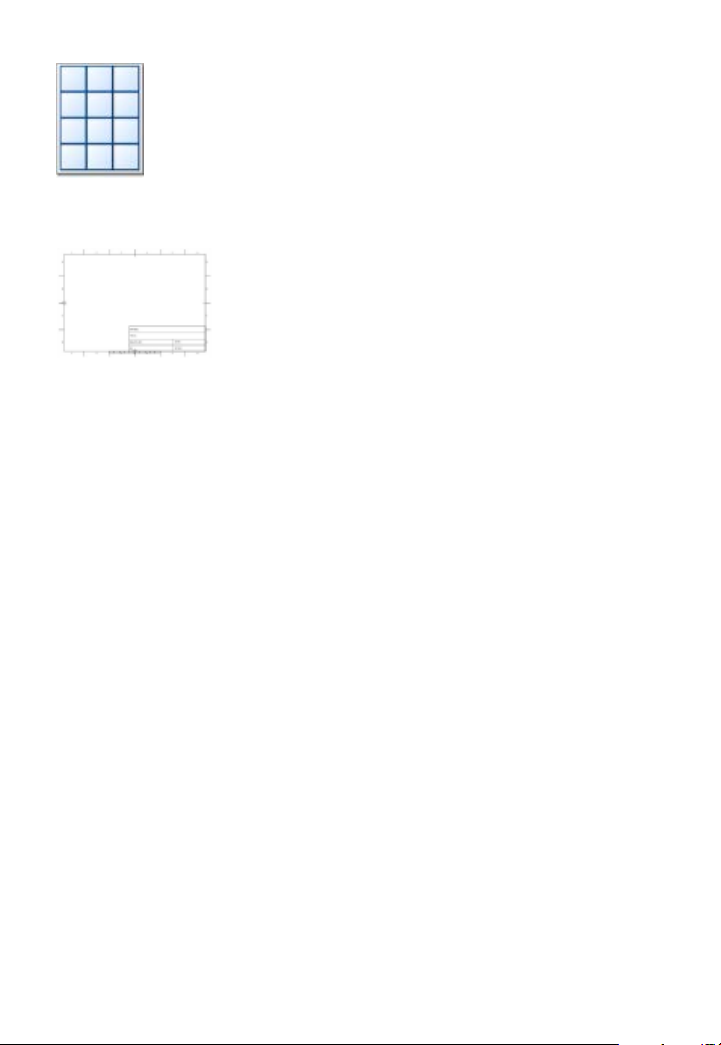
Labels, business cards, tags
Small
Publications
ISO and ANSI layouts
Technical
Drawing
To start a new drawing from scratch using the Startup
Assistant:
1. Start DrawPlus (or choose File>Startup Assistant if it’s already
running).
2. Select New Drawing from the Startup Assistant.
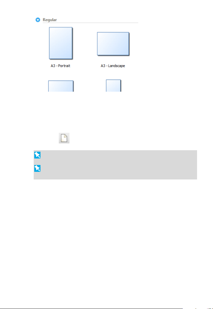
3. Review document categories in the right-hand pane (and sub-
categories if applicable). Categories contain preset document types
(see above) or if you select Regular, you can choose from standard
document sizes presented in Portrait or Landscape sub-categories.
4. Select a document type thumbnail from a category in the right-hand
pane.
Page 20
Getting Started 15
The new document opens.
To start a new drawing during your DrawPlus session:
• Click
New Blank Drawing on the Standard toolbar.
You can always adjust the page settings later via File>Page Setup.
To start with a new keyframe or stopframe animation, see Getting
started with animation on p. 142.
Opening a drawing
You can open an existing DrawPlus drawing from the Startup
Assistant, Standard toolbar or the File menu.
To open an existing document from the Startup
Assistant:
1. From the Startup Assistant, click Open. Recently opened files are
shown, such as today, last 7 days and Last 30 days.
2. Select a file to open it.
Page 21
16 Getting Started
To open an existing document via toolbar or menu:
1. Click
2. In the Open dialog, navigate to, then select the file name and click
the Open button.
Open on the Standard toolbar, or select File>Open.
You can also open a range of file types including images, PDF
documents, and Adobe Illustrator files.
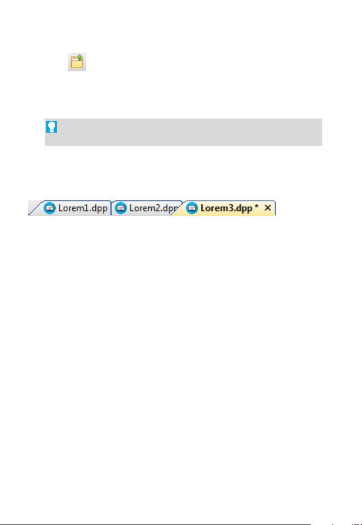
Once a drawing is opened in its own document window, the window
(and drawing) can be made currently active from a Document tab
(below) or via the Window menu.
Restore last session
Instead of launching the Startup Assistant, DrawPlus can restore your
last session. This option opens the file you most recently saved. You can
do this on an ad hoc basis when you open DrawPlus, or choose to always
restore the last session by default.
To restore your last session:
1. From the Startup Assistant, click Open.
2. Select Restore Last Session. The file opens.
Page 22
To always restore the last session:
Getting Started 17
1. From the drawing's context toolbar, select
2. From the Options>General menu option, select Restore Last
Session on the On start up drop-down list.
3. Click OK.
Options.
When using this feature, remember to close the DrawPlus program
at the end of your session (as opposed to closing individual
drawings). To do this, click at the very top-right of your
program.
For other options to customize DrawPlus, see Setting program
options in DrawPlus Help.
Saving your work
DrawPlus saves its documents as .dpp (Drawing), .dpx (Template) or
.dpa (Animation) files (for Stopframe and Keyframe animation modes).
To save your work:
• Click
- or To save the document under its current name, choose Save from
the File menu.
- or To save under a different name, choose Save As from the File
menu.
Save on the Standard toolbar.
Page 23
18 Getting Started
Setting measurement units and drawing scale
For precision drawing, you need techniques that allow you to position
and draw accurately without effort, that will also be of use at any scaled
size. Such techniques make use of rulers and guides for actual-size or
scaled drawings.
Rulers
The rulers that surround the page allow you to measure the exact
position of an object.
Ruler units used by DrawPlus determine the units displayed on the
rulers and the reported units shown when positioning and scaling
objects (either around the object or on the Hintline). You can change
the ruler units without altering the document's dimensions. Unit
settings are saved with your DrawPlus drawing; as a result loading
different drawings, templates, etc. may change your working
measurement units.
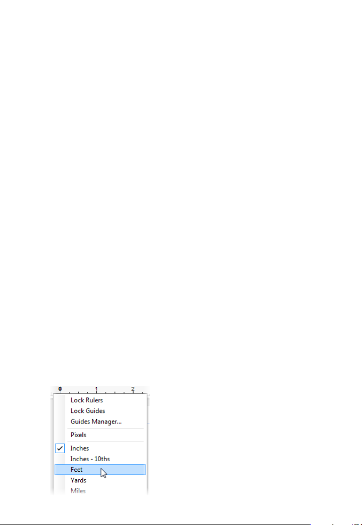
To change the measurement unit:
• Right-click on a ruler and select an alternative measurement unit.
Page 24
Getting Started 19
Ruler Units are equivalent to Page Units unless you're working on a
scale drawing. For example, one ruler centimetre equals one
centimetre on the printed page.
Creating guides
If you want to position objects repeatedly on the same horizontal or
vertical boundary then guides can be used. DrawPlus lets you set up
horizontal and vertical guides—non-printing, red lines you can use to
align one object with another.
Guides can be created (and positioned) either by dragging from a ruler
or via the Guides Manager (right-click any ruler). Both methods let you
add guides to the current page, or, if creating a folded document, guides
across a page spread.
To show/hide guides:
• To show or hide guides, check or uncheck Layout Tools>Guides
from the View menu.
Page 25
20 Getting Started
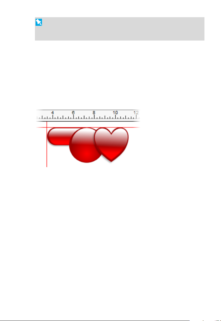
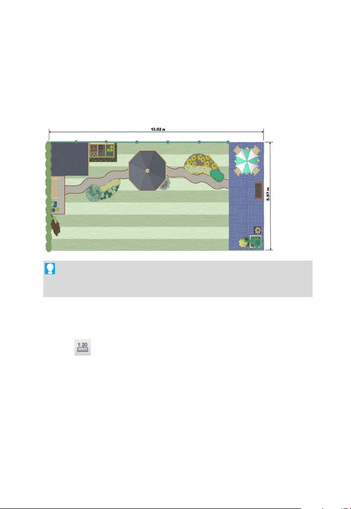
Drawing scale
You can create scale drawings (such as a home/garden design or model
diagram) by setting a ratio other than 1:1 between page units and ruler
units. For example, you might wish to set one page centimetre
equivalent to 0.5 metre, a good scaling ratio for designing gardens of a
typical size.
Use Dimension tools (see p. 49) in conjunction with scale drawings
for on-the-page measurements, which automatically update as you
move objects.
To change the drawing scale:
1. Choose
with the Pointer Tool selected). Choose
2. Check the Scale Drawing box.
3. Use the input boxes to set the drawing scale as a proportion between
the Page Distance (in page units that define the document's actual
printing dimensions) and the Ruler Distance (in on-screen ruler
units that represent the "real world" objects you're depicting).
Drawing Scale Options from the context toolbar (shown
Page 26
Getting Started 21
The Hintline toolbar at the bottom
Viewing pages
Once you've got a page in view, you can use the scrollbars at the right
and bottom of the main window to move the page and pasteboard with
respect to the main window. As you drag objects to the edge of the
screen the scroll bars adjust automatically as the object is kept in view.
of the screen displays the current
page number and provides a
number of controls to let you
navigate around your pages.
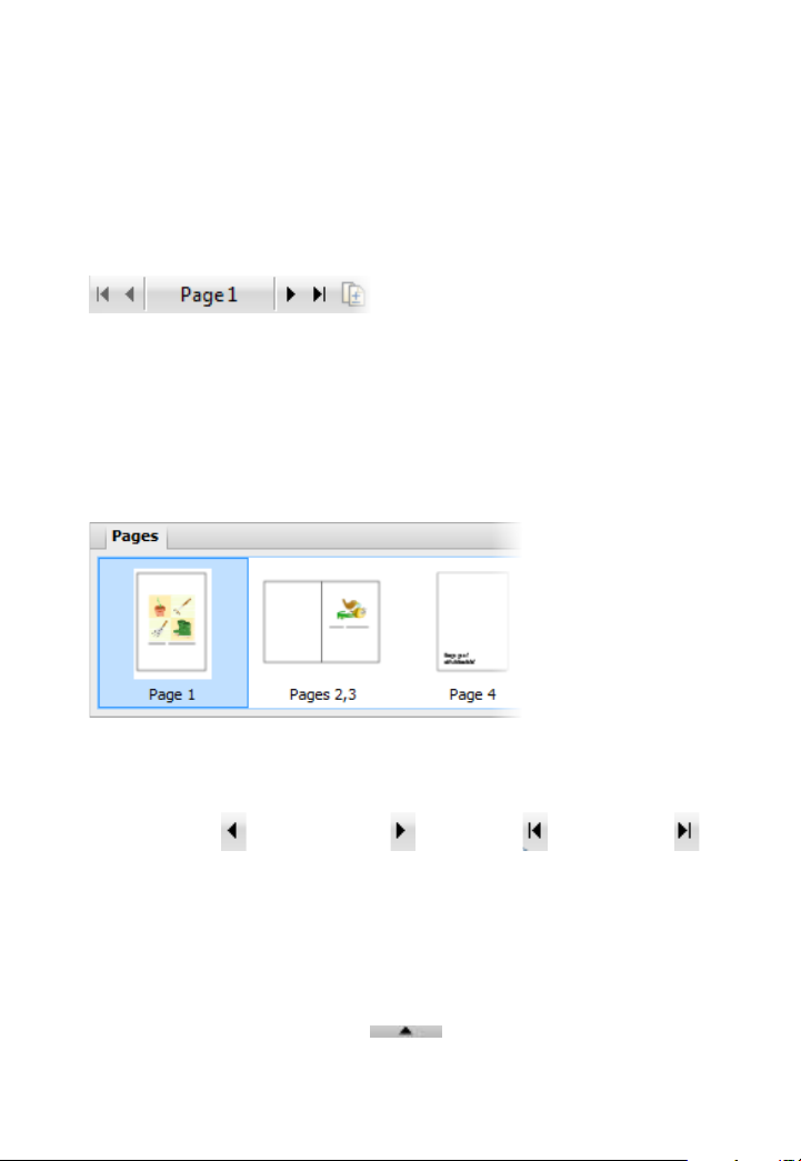
As an alternative, the Pages tab shows your pages as thumbnails, which
when selected, will display that page in your workspace.
To navigate pages:
• Click Previous page, Next page, First page or
Last page on the Hintline toolbar.
To go to a specific page:
1. Display the Pages tab (docked at the bottom of your DrawPlus
workspace) by clicking the
2. Click on a thumbnail to jump directly to that page.
button.
Page 27
22 Getting Started
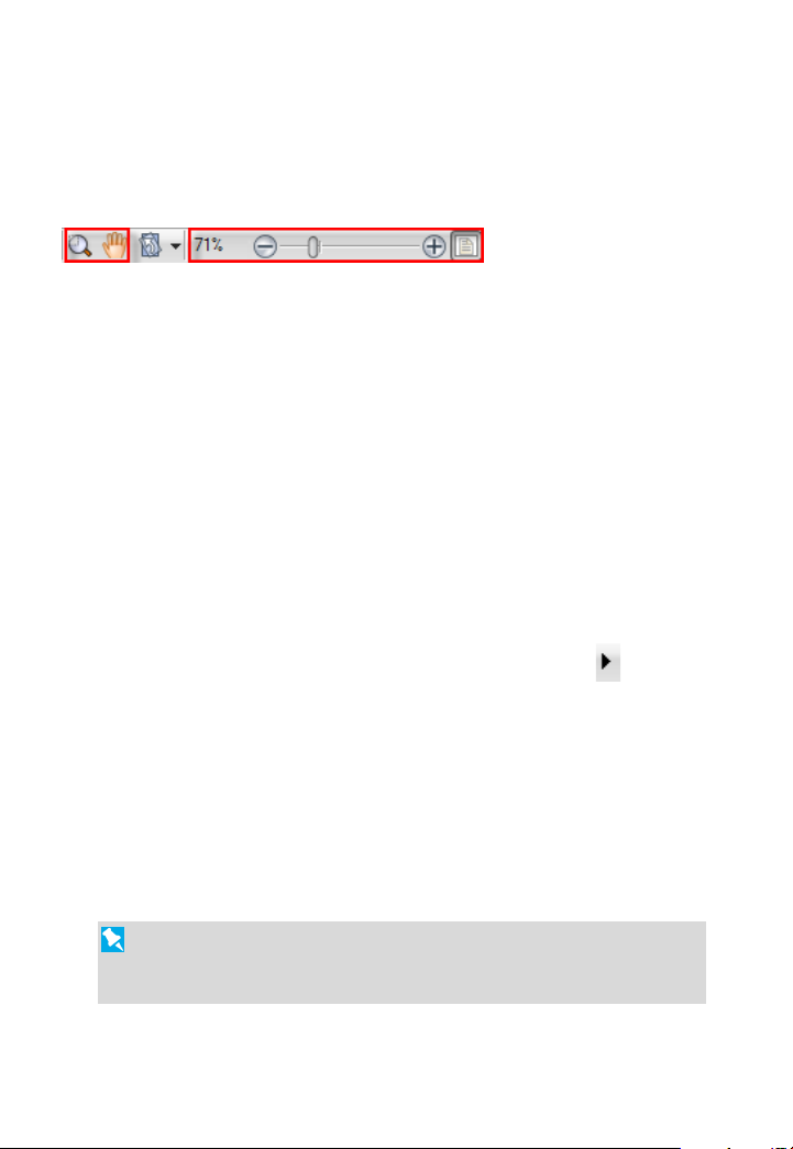
Zooming
The Hintline toolbar also allows the user to view and/or edit the page at
different levels of detail. You can use the Zoom Tool, Pan Tool,
Current Zoom, Zoom Out/In (with slider), and Fit Page options.
If you're using a wheel mouse, you can scroll the wheel forward or back
to move up or down the page. Try combining the Ctrl key and scrolling
up or down for immediate in/out zoom control.
Adding and deleting pages
DrawPlus lets you add a page after the last page in your drawing. You
can also add one or more pages before or after a currently selected page;
you can also copy objects from a chosen page.
To add a new page:
• From the last page of the current drawing, click the
Page button on the Hintline toolbar.
To delete one or more pages:
• On Page Manager's Delete Page tab, specify the number of
pages to delete and the page after which pages should be
deleted.
The document format (as determined in File>Page Setup) will
determine whether or not you can add or delete pages. For
example, Folded documents have a fixed number of pages.
Next
Page 28

Lines, Curves,
and Shapes
Page 29
24 Lines, Curves and Shapes
Pointer Tool
C
objects. You can select and rotate an object around a centre of
rotation.
Node Tool
Click to use the
move or copy objects.
Selecting one or more objects
Before you can change any object, you need to select it using one of
several tools available from the top of the Drawing toolbar.
lick the Pointer Tool to select, move, copy, resize, or rotate
Node Tool to manipulate the shape of objects, or
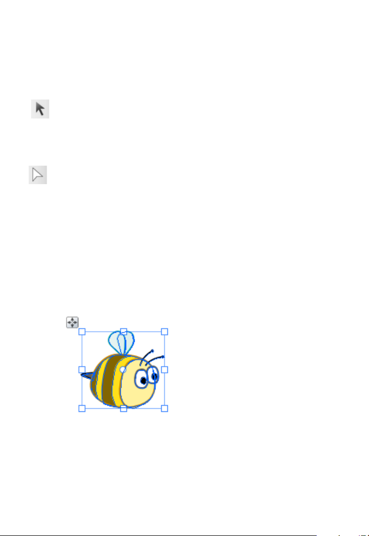
To select an object:
• Click on the object using one of the tools shown above. For the
Pointer Tool, small "handles" appear around the object
indicating selection.
For the Node Tool, editable nodes are displayed for lines—
sliding handles are additionally shown for adjustment of
QuickShapes and text. If objects overlap, use the Alt key while
clicking repeatedly until the desired item is selected.
Page 30
Lines, Curves and Shapes 25
If an object won't select, it may be on another layer. Try clicking
Edit All Layers on the Layers tab to allow selections to be made on
any layer.
Selecting multiple objects
It is also possible to select more than one object, making a multiple
selection that you can manipulate as if it were one object, or turn into a
grouped object (p. 80).
To select more than one object (multiple selection):
1. Choose the Pointer Tool.
2. Click in a blank area of the page and drag a "marquee" box around
the objects you want to select.
Release the mouse button. All of the objects within the marquee box
are selected and one selection box, with handles, appears around the
objects. To deselect, click in a blank area of the page.
- or -
3. Click on the first object for selection.
Page 31

26 Lines, Curves and Shapes
4. Press the Shift key down then click on a second object.
5. Continue selecting other objects to build up your multiple selection.
Handles (or a bounding box, depending on the tool) appear around
the multiple selection.
To select all objects on the page:
• Choose Select All from the Edit menu (or use Ctrl+A).
To add or remove an object from a multiple selection:
• Hold down the Shift key and click the object to be added or
removed.
If you have one or more objects selected, you can select all other
unselected page objects instead; the originally selected objects become
deselected.
To invert a selection:
• From the Edit menu, select Invert Selection.
For very precise object selection, you can draw a lasso around an
object to select it (press the Alt Key down with the selection tool
enabled, then drag around the object ).
Page 32

Drawing lines and shapes
Lines, Curves and Shapes 27
Lines can be either straight or curved, and can have properties like
colour and width (thickness). They can also adopt specific line styles,
ends, and caps.
If you're using a pen tablet or using simulated pressure sensitivity (with
DrawPlus's Pressure tab), you'll be able to draw realistic lines of varying
width and opacity using pressure sensitivity—just like drawing with real
pencils and pens.
To draw a freeform line:
1. Choose the
Pencil Tool from the Drawing toolbar.
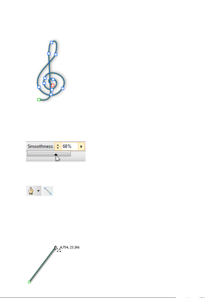
2. Click once, then drag across the page, drawing a line as you go. The
line appears immediately and follows your mouse movements.
3. To end the line, release the mouse button. The line will
automatically smooth out using a minimal number of nodes.
Page 33
28 Lines, Curves and Shapes
Note the little squares indicating its nodes—at the two ends, and at
each point where two line segments come together.
4. (Optional) To set the degree of smoothing to be applied to the line
(and subsequent lines), set the Smoothness value on the context
toolbar above your workspace.
To draw a straight line:
1.
From the Drawing toolbar's Line Tools flyout, click
the Straight Line Tool.
2. Click where you want the line to start, and drag to another point
while holding down the mouse button, then release the mouse
button. The straight line appears immediately.
Page 34
Lines, Curves and Shapes 29
Any kind of open line (that is, one that hasn’t been closed to create a
shape) can be extended, and you can use any of the three line tools to do
so.
To extend a line:
1. Move the cursor over either of the end nodes, a small cursor will
appear. Click at that location.
2. The line that you drag out will be a continuation of the existing line,
as a new line segment.
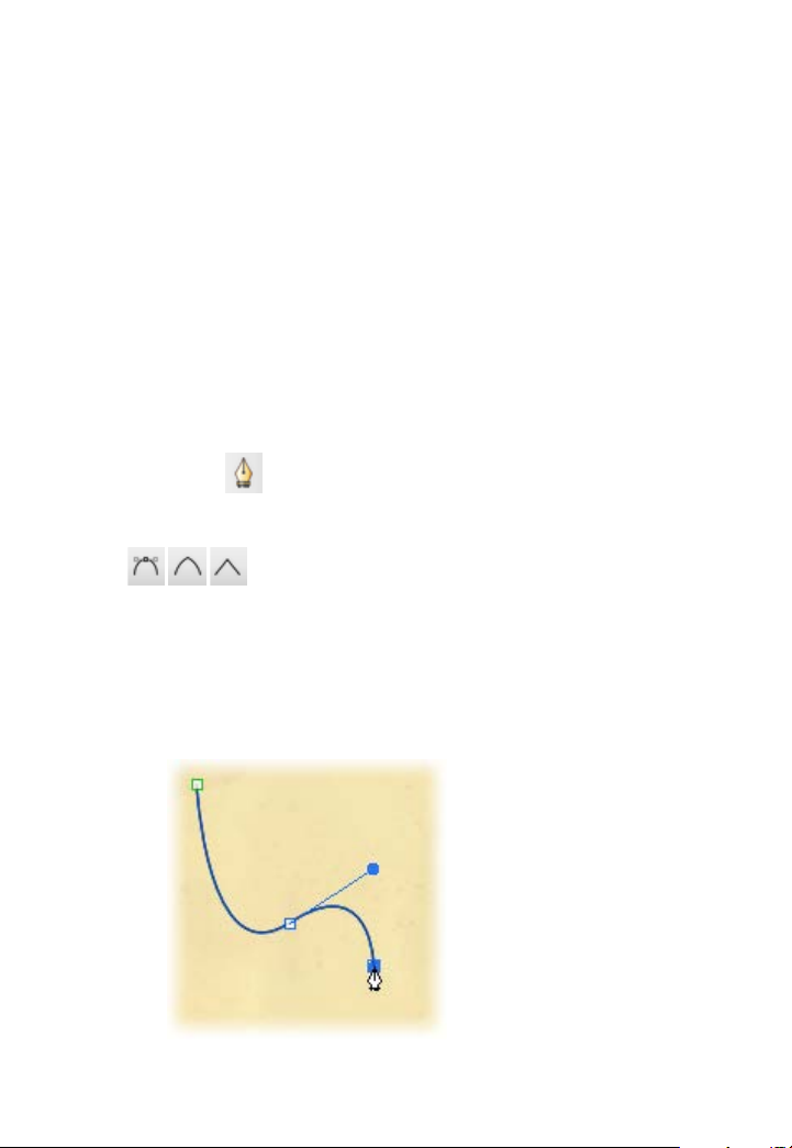
To draw a curved line:
1. Choose the
Pen Tool from the Drawing toolbar's Pen Tools
flyout.
2.
From the displayed context toolbar, choose to create your
drawn segments in Smooth, Smart, or Line Segments creation Mode.
• Smooth Segments: draws Bézier curves smoothly segment-by-
segment, with manual on-curve and off-curve adjustment via
nodes and control handles, respectively.
Page 35
30 Lines, Curves and Shapes
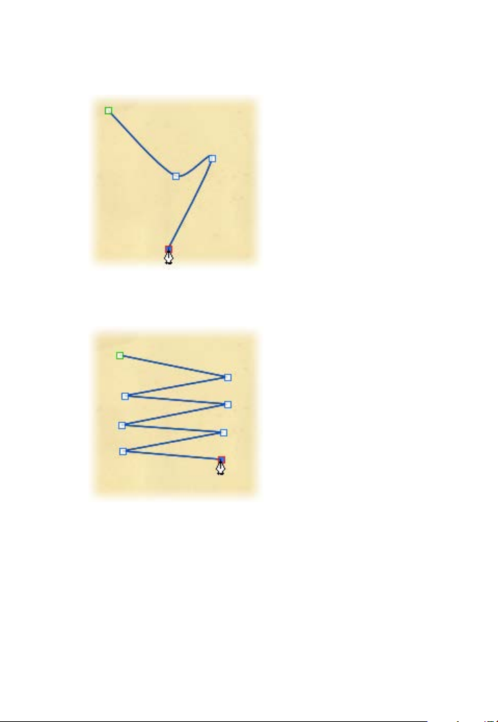
• Smart Segments (default): automatically determines slope and
depth for a rounded, best-fitting curve. No control handle
adjustment is normally necessary.
• Line Segments: creates a zigzag line without curving through
nodes.
See DrawPlus Help for an in-depth look at drawing lines in each of these
modes.
Page 36

Lines, Curves and Shapes 31
Drawing shapes
When a line (or series of line segments) forms a complete, enclosed
outline, it becomes a new closed object called a shape. Because shapes
have an interior region that can be filled (for example, with a solid
colour, vector or a bitmap), they have fill properties as well as line
properties.
You can make a shape by closing a curve—extending a freeform line or a
segmented straight line back to its starting point. Shapes have an interior
which is filled with the current default fill (see Setting fill properties on
p. 92) when the shape is closed.
To close an existing curve (with a straight line):
1. Select the curve with the Node Tool, Pencil or Pen Tool.
2. Click
Close Curve on the context toolbar. A Straight segment
appears, closing the curve.
To close a curve (without new segment):
1. Select the curve with the Node Tool.
Page 37

32 Lines, Curves and Shapes
If you're trying to draw an outline made up
2. Using the node cursor, click on an end node and drag the curve
onto the other end node and release the mouse button to create a
shape.
of many independent curves (e.g., a cartoon
ear, rose, etc.) and you want to retain the fill
colour, you can fill each curve without
closing them. This is made easy by using
the Fill-on-Create feature.
To fill an unclosed curve automatically:
1. Select the Pencil Tool, Pen Tool, or Brush Tool.
2. Enable
Fill-on-Create from the context toolbar, and select a
suitable fill from the Colour tab. You'll also need to ensure Select-
on-Create is enabled on the context toolbar (Freehand and Brush
tools only).
3. Draw a freeform line, pen line, or brush stroke into a curve. The
resulting curve is filled with the current fill colour.
Drawing B-Spline curves
The B-Spline Tool draws smooth curves when you create open or closed
shapes. B-spline, also known as Basis spline, uses a mathematical
formula. It is this calculation that produces really nice elegant curves.
When you use the B-Spline Tool, control points are connected together
as you draw and a polygon is constructed. The polygon controls the
position and direction and calculates the smoothest possible curve
between two points on the page.
Page 38

Lines, Curves and Shapes 33
A - control point, B - control polygon, C - B-spline curve
When you still want nice curves and your object may need some flat
sections, you can clamp control points to create sharp corners and
straight lines. You can also convert B-Splines to Beziers for flexible
editing as you prefer. The B-Spline Tool is especially useful for tracing
curved objects such as a musical note to make perfect duplicates, or the
tear example shown.
Creating curves with the B-Spline Tool
To create an open curve:
1. Click arrow next to the
display the Line Tools flyout.
2. From the flyout, select the
3. Position your cursor on the page where you want to start drawing.
Pen Tool on the Drawing toolbar to
B-Spline Tool.
Page 39

34 Lines, Curves and Shapes
4. Click once to add the first control point.
5. On the page, position the cursor at the next point.
A polygon line extends from the current point.
6. Click once to add a second point.
A straight B-spline curve is added to the page and follows the
polygon line.
To draw a sharp corner or a straight line, press the Alt key.
7. Position the cursor at the next point.
Page 40

Lines, Curves and Shapes 35
The polygon line extends from the current point. The B-spline
curve created by the polygon displays.
8. Click to add another point and repeat for as many more as you
need.
The control polygon extends and the B-spline curve updates as you
do this.
9. When you are finished with the curve, press the Esc key to cancel
the selection.
To create a closed shape:
1. With the B-Spline Tool selected, position your cursor on the page
and click to add the first control point as before.
2. Position the cursor at the next point and click again.
3. Position the cursor again in a place and click for each subsequent
point required.
4. To close the shape, position the cursor over the first control point
and click once followed by Esc.
Creating sharp corners or straight lines
You can create sharp corners or straight lines by clamping control
points of your B-spline curve to the control polygon. If you clamp one
Page 41

36 Lines, Curves and Shapes
control point, you will get a sharp corner but not a straight line or a
curve. If you clamp two adjacent control points, you'll get a perfect
straight line between them. You can hold the Shift key if you want to
select and clamp multiple control points concurrently.
To use clamping:
1.
With the curve or shape selected, on the Drawing toolbar, select
the B-Spline Tool.
2. Select the control points you require.
3. On the context toolbar, click
Clamp Curve to clamp, or
Unclamp Curve to unclamp any control points.
Editing B-splines
You can edit your B-spline curve by manipulating its control points in a
similar way that you would when moving nodes around after having
drawn a line or a shape with the Pen or Pencil Tool.
To edit a B-spline:
1.
2. Select a control point.
3. Drag the control point into a new position. The control polygon
With the curve or shape selected, on the Drawing toolbar, select
the B-Spline Tool.
gives you a preview of how the curve will change as you drag.
Other editing options available are creating sharp corners or straight
lines within your shape or curve, and also converting a B-spline to a
Bézier.
Page 42

Lines, Curves and Shapes 37
Using QuickShapes
QuickShapes are pre-designed objects that you can instantly add to your
page, then adjust and morph into a variety of further QuickShapes.
QuickShapes are added from a flyout containing a wide variety of
commonly used shapes, including boxes, arrows, hearts, spirals and
other useful symbols.
Morphing to new shapes can be carried out after you add the
QuickShape to the page (or as you add by double-clicking on the page).
To create a QuickShape:
1. Click the down arrow on the
QuickShape button on the
Drawing toolbar, then select a shape from the flyout.
The button takes on the icon of the shape you selected.
2. At your chosen cursor position, click and drag on the page to draw
out your QuickShape to a chosen size (use the Shift key to lock the
aspect ratio; the Ctrl key to scale from its centre point; or both
together).
New QuickShapes adopt the currently set line and fill in DrawPlus.
Page 43

38 Lines, Curves and Shapes
Ctrl-double-click to place a default-sized QuickShape on the page.
To adjust the appearance of a QuickShape:
1. With the
QuickShape to reveal sliding handles around the shape. These are
distinct from the "inner" selection handles. Different QuickShapes
have different handles.
2. Drag any handle to change the appearance of the QuickShape.
For example, by dragging the top sliding handle to the right of the shape
below will produce a different shape variant:
Node Tool (Drawing toolbar) selected, click on the
Flooding areas
The Flood Tool lets you quickly flood areas with colour. The Tool will
look for any edges that are visual boundaries in your drawing. It then
creates a shape which floods the area between the edges. This gives you
the option of easily flooding closed sections of an object's areas.
Page 44

Lines, Curves and Shapes 39
The noughts and crosses example was flooded with colour using the
Flood Tool. The tool flooded the noughts, crosses, squares and border
objects even though they were separate items. You could also easily
flood any traces that you have done with the Pen Tool.
Areas are flooded by pixels and the shapes you create then become
editable like any other object you might want to transform.
Specifying flood settings
There are some settings that accompany the Flood Tool which can be
specified before or after you have flooded.
To specify flood settings:
1. On the Drawing toolbar, click the arrow next to the
Freeform
Paint Tool.
This will display the Vector Edit Tools flyout.
2. From the flyout, select the
Flood Tool.
3. On the Context toolbar, specify the settings shown below.
Page 45

40 Lines, Curves and Shapes
If you don't want to bother with these settings and you just want to
start flooding, see To flood an area on p. 40.
• Tolerance: This defines the difference from the starting pixel
where the boundary will be drawn. Any pixel which is less than
the tolerance in difference to the starting pixel, and is
connected to the starting pixel by other similar pixels will be
filled. Any connected pixel which is more different than the
tolerance will be considered a boundary and will not be filled.
• Feature Size: This controls the accuracy of the flood. A smaller
value ensures an accurately shaped flood.
• Inflate / Deflate: The created flood will be resized based on this
value. Inflate (positive values) can be used to ensure there are
no gaps. Deflate (negative values) can be used for artistic effect.
• Apply Line Style: Automatically apply the line style to the
created flood using the style currently set in the Line tab.
• Select-on-Create: Upon flooding, the flood object is
automatically selected for editing.
Flooding an area
Once you have applied the optional flood settings, you can start
flooding. Based on the settings, DrawPlus will flood the visual boundary
of an area with a colour or fill specified in the
To flood an area:
1. On the Drawing toolbar, click the arrow next to the
Paint Tool. This will display the Vector Edit Tools flyout.
2. From the flyout, select the
Flood Tool.
Fill swatch.
Freeform
Page 46

Lines, Curves and Shapes 41
3. On the Colour tab, pick a colour for the Fill/Line Swatch.
You can also apply preset solid colours or transparency effects.
4. Select a visual area and left-click it.
5. Repeat as necessary for any additional colours you want. If you have
Select-on-Create enabled, you'll need to select the select the Flood
Tool again.
6. If Select-on-Create is enabled, once the flood has been created, use
the Clean Curves option on the Context toolbar to remove
unnecessary nodes and smoothen the edges of your shape.
Editing flood shapes
Once you have finished flooding, you can edit flood shapes by using the
Pointer Tool to select, move and resize them.
Page 47

42 Lines, Curves and Shapes
To edit a flooded shape:
1. On the Drawing toolbar, select the
2. Click and drag an individual flooded shape or the original object
away from other objects.
3. Apply any modifications as needed.
Pointer Tool.
Editing lines and shapes
To edit lines or shapes, you can manipulate their segments, on-curve
nodes, and off-curve control handles allowing you to:
• Redraw part of a line
• Reshape a line
• Simplify a line (remove nodes)
• Enhance a line (add nodes)
• Change the type of node or line segment
The procedures below relate to lines drawn with the Pencil Tool, but
also to curves drawn with the Pen Tool. For simplicity, we'll only use
the term line.
Page 48

Lines, Curves and Shapes 43
Redrawing part of a line
With the Pencil Tool, it's easy to redraw any portion of a line.
To redraw part of a selected line:
1. Select the line, then the
Pencil Tool. Hover the displayed
cursor on the line where you want to begin redrawing. The cursor
changes to indicate you can begin drawing.
2. Double-click on the line. A new node appears.
3. Keep the mouse button down and drag to draw a new line section,
connecting it back to another point on the original line. Again, the
cursor changes to include a curve when you’re close enough to the
line to make a connection. When you release the mouse button, the
original portion is replaced by the newly drawn portion.
Reshaping a line
The main tool for editing lines and shapes is the Node Tool. You can
drag segments or select one or more nodes on the object, then use the
buttons on the tool's supporting context toolbar to adjust.
Page 49

44 Lines, Curves and Shapes
To reshape a curved line:
1. Click the
Node Tool on the Drawing toolbar.
2. Select any line on your page. The line’s on-curve nodes appear, and
the context toolbar also pops up.
3. Hover over a segment and drag the segment to form a new curve
shape.
-or-
Select nodes and drag. Selection can be by one of the following
methods:
Hover over a single
node and click to
select the node.
Shift-click for
multiple nodes.
Drag out a
marquee to select
multiple
neighbouring
nodes
Drag out a lasso
(with Alt key pressed)
to select multiple
nodes otherwise
difficult to select via a
marquee.
Page 50

Once a square end node or interior node is
selected, the node becomes highlighted and offcurve rounded control handles for all line
segment(s) will appear. A single control handle
shows on an end node; a pair of handles will show
on a selected interior node.
Remember that a segment is the line between two
nodes; each node provides two control handles,
with each handle controlling different adjoining
segments. One control handle in a segment works
in conjunction with the control handle on the
opposite end of the segment.
Lines, Curves and Shapes 45
(A) Line Segment 1, (B) Line Segment 2
4. Drag any selected node to reshape adjacent segment(s).
5. Drag one or more control handles to produce very precise changes
in the curvature of the line on either side of a node. You can shorten
or lengthen the handles, which changes the depth of the curve (that
is, how far out the curve extends), or alter the handle angle, which
changes the curve’s slope.
Page 51

46 Lines, Curves and Shapes
Simplifying or enhancing a line
The more nodes there are on a line or shape, the more control over its
shape you have. The fewer nodes there are, the simpler (smoother) the
line or shape.
To adjust the smoothness of the most recent pencil line:
1. Choose the
Pencil Tool and draw a freeform line.
2. From the context toolbar, click the right arrow on the Smoothness
option and drag the displayed slider left to increase the number of
nodes.
3. To make the curve less complex, i.e. smoother, drag the slider right
to decrease the number of nodes.
To add or delete a node:
• To add a node, click along a line segment with the Node Tool
or Pen Tool to add a new node at that point. The new node will
be created and will be selected.
•
To delete a node, select the line with the Node Tool then
the node itself and click the Delete Node button on the context
toolbar (or press the Delete key). The node will be deleted, and
the line or shape will jump to its new shape. With the Pen Tool
selected, you can also delete a node by clicking on it.
You can also use the Node Tool to reposition the nodes, and reshape the
line or shape, by dragging on the new handles.
Page 52

Lines, Curves and Shapes 47
Changing nodes and line segments
Each segment in a line has a control handle at either end, so at each
interior or "corner" node (where two segments join) you'll see a pair of
handles. The behaviour of these handles—and thus the curvature of the
segments to either side—depends on whether the node is set to be sharp,
smooth, symmetric, or smart. You can quickly identify a node's type by
selecting it and seeing which button is selected in the displayed context
toolbar. Each type's control handles behave differently as described
below.
To change one or more nodes to a different type:
1. Select the object with the Node Tool, followed by the node(s) you
want to change.
2. Click one of the node buttons on the displayed context toolbar.
A Sharp Corner means that the line segments to either
side of the node are completely independent so that the corner
can be quite pointed.
A Smooth Corner uses Bézier curves, which means that
the slope of the line is the same on both sides of the node, but
the depth of the two joined segments can be different.
At a Symmetric Corner, nodes join line segments with the
same slope and depth on both sides of the node.
Smart Corner nodes automatically determine slope and
depth for a rounded, best-fitting curve. If you attempt to adjust
a smart corner's handles, it becomes a smooth corner. You can
always reset the node to smart—but to maintain smart nodes,
be careful what you click on!
Page 53

48 Lines, Curves and Shapes
Converting a shape to editable curves
The conversion of QuickShapes to curves provides you with a starting
point for your own shapes (below), whereas converting text to curves is
one way of incorporating editable letter-based shapes into designs.
Converting an object into curves cannot be reversed later on!
To convert an object into curves:
1. Select your QuickShape or text object.
2. Click
With the
outline by dragging selected nodes.
Convert to Curves on the Arrange tab.
Node Tool enabled (Drawing toolbar), edit the curve
The conversion process loses all of the special properties inherent in
QuickShapes and text.
Page 54

Lines, Curves and Shapes 49
Adding dimension lines and labels
DrawPlus lets you add dimension lines with text labels showing the
distance between two fixed points in a drawing, or the angle formed by
three points. For example, you can draw a dimension line along one side
of a box, measuring the distance between the two corner points. If you
resize the box, the line automatically follows suit, and its label text
updates to reflect the new measurement.
You’ll find dimension lines indispensable for planning garden designs
(e.g., a garden gazebo plan), technical diagrams, floor plans, or any
drawing where exact measurements and scale are important.
Although they can be drawn anywhere on the page, dimension lines are
at their most accurate when attached to connection points on objects or
when snapped to dynamic guides (see DrawPlus Help).
Page 55

50 Lines, Curves and Shapes
To draw a dimension:
1.
From the Drawing toolbar’s Connector Tool flyout, select
the Dimension Tool. (The flyout shows the icon of the most recently
selected tool.)
2. Either, for a linear dimension, click the respective tool from the
Dimension context toolbar:
•
Auto Dimension Line Tool.
Use to draw vertical, horizontal, or diagonal dimension lines in
any direction, with automatic placement of the editable
dimension label adjacent to the line.
Click where you want to start the dimension line (e.g., on a
connection point), then drag and release the mouse button
where you want to end the line (maybe on another connection
point). The illustrations below show the result of dragging
between connection points on two Quick Squares with the
Auto Dimension Line Tool enabled.
Page 56

Lines, Curves and Shapes 51
• Vertical Dimension Line Tool.
Ideal for vertical dimension lines, the label information is
always presented vertically with the option to move the label by
dragging. Extension lines are used to present the dimension
line vertically and to allow for an optional offset.
•
Horizontal Dimension Line Tool.
As above but for horizontal dimension lines.
•
Slanted Dimension Line Tool.
Designed specifically for drawing diagonal dimension lines.
- or -
For an angular dimension, click the
Angular Dimension
Line Tool then click and drag from a corner node towards the
angle you want to measure (A). Release the mouse button over
the "target" angle, then move your mouse cursor to the next
corner node, then click on that node (B) to set the angle to be
measured.
To complete the dimension line, move the mouse again to
position the floating line and its label—note that they respond
independently—and click when they are where you want them
(C). (You can always change the positions later.) The dimension
line appears.
Page 57

52 Lines, Curves and Shapes
The Studio's Gallery tab
We've used a triangle as an example above and made use of the
nodes that show by default. However, DrawPlus will allow you to
add dimension lines between separate objects, and define your
target angle from any point on the object or page.
Instead of displaying an inner angle, drag the dimension line and
label to the outer angle to display its obtuse equivalent.
Press the Esc key while drawing your dimension line to cancel the
operation.
Adjusting dimension lines
For all dimension tools, a pair of parallel blue extension lines with blue
end nodes appears on the dimension line, along with a node on the label
box. Between the two extension lines, the dimension line and its label
can "float" by moving the blue nodes.
Using the Gallery
contains pre-built design
objects and elements you'd like
to reuse in different drawings.
You can choose designs stored
under Clipart (like Animals),
Home, Office, School,
ShapeArt, and Web folders.
Page 58

Lines, Curves and Shapes 53
The Gallery tab also lets you store your own designs in a My Designs
section if you would like to reuse them—the design is made available in
any DrawPlus drawing.
To view your Gallery:
• Click the Studio's Gallery tab.
• Select a folder or category from the drop-down list. The items
from the folder's first listed category are displayed by default.
To use a design from the Gallery:
• Drag any preset design directly onto the page. You can modify,
then drag the design back into your own custom category.
To copy an object into the Gallery:
1. Display the Gallery tab's My Designs (or sub-category of that)
where you want to store the object.
2. Drag the object from the page and drop it onto the gallery.
3. You'll be prompted to type a name for the design. (You can name or
rename the design later, if you wish.) By default, designs are labelled
as "Untitled."
4. A thumbnail of the design appears in the gallery, labelled with its
name.
To delete or rename a custom design:
• Right-click its gallery thumbnail and choose Delete Design or
Rename Design from the submenu.
Page 59

54 Lines, Curves and Shapes
Page 60

Using Brushes
and Te xt
Page 61

56 Using Brushes and Text
Applying brush strokes
The Brush Tool is used exclusively to apply
brush strokes to the page. The tool is used in
conjunction with the Brushes tab, and a
supporting context toolbar.
To apply a brush stroke:
1. Select the
Brush Tool from the Drawing toolbar.
2. Display the Brushes tab and choose a category from the drop-down list,
then a brush.
Page 62

Using Brushes and Text 57
3. Select a Line Colour, Width, or Opacity from the context toolbar.
4. With the
stroke.
brush cursor, drag across your page to create a brush
Photo brushes, available from the Brushes tab (Photo category), can
be recoloured just as any other brush type.
You can also apply a brush stroke around an object's outline
(shape, artistic text, picture, etc.) via Brush Stroke on the Line tab.
See Setting line properties on p. 97.
Setting brush defaults
See Updating defaults in DrawPlus Help.
Editing brush strokes
It's possible to alter any previously drawn brush stroke with respect to its
properties, brush type, and shape. The Pointer Tool or Node Tool can
be used to select the brush stroke, which will then allow it to be edited.
To change brush stroke properties:
• With the brush stroke selected, use the context toolbar to adjust the
properties of a brush stroke once it has been drawn on the page.
Page 63

58 Using Brushes and Text
To change brush stroke type:
1. Select the brush stroke.
2. Go to the Brushes tab and select firstly a brush category, then a
brush type from the displayed gallery. The brush stroke adopts the
newly chosen brush.
Brush types currently applied to your brush strokes are handily
listed in the Document folder of the Brushes tab.
To change the shape of your brush stroke:
A brush stroke possesses very similar characteristics to a plain line.
Any brush stroke can therefore be edited, extended, or redrawn with the
Node Tool (Drawing toolbar) just as for a straight or curved line (see
Editing lines and shapes on p. 42). Use for fine-tuning your brush
strokes after application.
Pressure sensitivity
Via a Pen Tablet
Your pen tablet and DrawPlus work in perfect harmony for a truly
authentic drawing and painting experience, with in-built pressure
sensitivity as you draw and paint. See DrawPlus Help for more
information.
Page 64

Using Brushes and Text 59
Via the Pressure Tab
If a pen tablet is unavailable to you, DrawPlus can simulate pressure
sensitivity when using your mouse (along with DrawPlus’s Pressure tab).
This tab is used to set pressure sensitivity globally by using a pressure
profile.
To apply a pressure profile:
1. Expand the Pressure tab at the bottom right of your screen, and
choose a pressure profile from the drop-down list.
The pressure chart updates to reflect the chosen profile.
2. Apply a brush stroke or draw a line on the page. This will adopt the
chosen pressure profile.
The profile is maintained until you reset it or pick another profile from
the preset list. As well as using the preset profiles you can also create
your own custom profile. (See DrawPlus Help for more details.)
Page 65

60 Using Brushes and Text
Entering text
You can create different types of text in DrawPlus, i.e. Artistic Text,
Frame Text, or Shape Text, all directly on the page.
Artistic Text Frame Text Shape Text
It's easy to edit the text once it's created, by retyping it or altering
properties like font, style, and point size.
In general, artistic text (as an independent object) is better suited to
decorative or fancy typographic design, frame text is intended for
presenting text passages in more traditional square or rectangular
shaped blocks; shape text lends itself so well to blocks of body text where
shape and flow contribute to the overall layout.
To enter new artistic text: :
1. Select
Artistic Text Tool on the Drawing toolbar's Text
flyout.
2. To create artistic text at the current default point size, click where
you want to start the text.
- or -
For artistic text that will be automatically sized into an area, click
and drag out the area to the desired size.
Page 66

Using Brushes and Text 61
3. To set text attributes (font, size, etc.) before you start typing, make
selections on the Text context toolbar. For colour, set the Line/Fill
swatches on the Studio's Colour or Swatch tab.
4. Start typing.
To create frame text: :
1. Select
Frame Text Tool on the Drawing toolbar's Text
flyout.
2. From the positioned cursor, either:
• Double-click on the page to create a new frame at a default size.
- or -
• Drag out a frame to your desired frame dimension.
3. (Optional) Set text and colour attributes as for artistic text before
you start typing.
4. Start typing within the frame.
To enter new shape text:
1. Create a QuickShape either from the Drawing toolbar's QuickShape
flyout or by closing a drawn line.
2. With a shape still selected, select
Artistic Text (Drawing toolbar)
and just start typing.
For existing shapes without shape text, select the shape, then the Artistic
Text Tool, then begin typing.
Page 67

62 Using Brushes and Text
Editing text
Once you've entered either artistic, frame or shape text (see Entering
text on p. 60), you can retype it and/or format its character attributes
(font, point size, bold/italic/underline, subscript/superscript, OpenType
font features, etc.), paragraph properties, and text flow.
For a gradient or bitmap fill, use the Studio's Swatch tab. See p. 102 or
p. 105, respectively.
Similarly, opacity is applied from the Colour tab (see p. 107); gradient
and bitmap transparency from the Transparency tab.
Retyping text
You can either retype artistic, frame or shape text directly on the page,
or use the Edit Text window—great for managing large amounts of text
(overflowed shape text or otherwise) in a simple word processing
environment.
To retype text on the page:
1.
2. Type new text at the selection point or drag to select text, then type
From the Drawing toolbar's Text flyout, select Artistic
Text, then click on the text.
to replace it. To cut, copy, and paste, use the toolbar buttons or
standard Windows keyboard shortcuts.
Page 68

Using Brushes and Text 63
To create a new line:
• At the position you want to start a new line, press the Enter key.
Formatting text
You can change text formatting (character, paragraph,
bullets/numbering and text flow properties) directly on the page via the
Text context toolbar or via a Text Style dialog.
To format selected text on the page:
1. Use the
Alternatively, drag select on any text with
Drawing toolbar's Text flyout).
2. Use the Text context toolbar to change text properties (font, point
size, bold/italic/underline, subscript/superscript, OpenType font
features, text alignment, bullets and numbering, levels, and text
fitting).
Pointer Tool to select the text you want to change.
Artistic Text (from the
For greater control over the shape of the artistic text characters, try
converting the artistic text to curves. For details, see Converting a
shape to editable curves on p. 48.
Fitting text to a path
DrawPlus allows you to make artistic text conform to a curved baseline
(such as a drawn freeform line or curve), custom shape or a preset shape
(QuickShape).
Page 69

64 Using Brushes and Text
To fit text to a path:
1. Select the curve or shape.
2. Select
3. Hover over the curve or shape's outline until you see a
Artistic Text on the Drawing toolbar's Text flyout.
cursor,
then click at the point on the line where your text is to begin.
4. Begin typing your text. The text will be placed along the curve or
shape.
To flow text along a preset path:
1. Select your artistic text.
2.
From the context toolbar, click the down arrow on the Preset
Text Paths button and select a preset curve from the drop-down list
on which the text will flows.
Page 70

Working with
Objects
Page 71

66 Working with Objects
Copying, pasting, cutting, and deleting objects
To copy one or more objects to the Windows Clipboard:
1. Select the object(s).
2. Click the
If you're using another Windows application, you can usually copy and
paste objects via the Clipboard.
To paste an object from the Clipboard:
• Click the
The standard Paste command inserts a clipboard object onto the page.
Copy button on the Standard toolbar.
Paste button on the Standard toolbar.
To select the type of object to be pasted from the Clipboard, choose
Paste Special from the Edit menu.
To cut one or more objects to the Clipboard:
1. Select the object(s).
2. Click the
The object is deleted from the page and a copy is placed on the Windows
Clipboard.
Cut button on the Standard toolbar.
To delete one or more objects:
• Select the object(s) with the Pointer or Node Tool and press the
Delete key.
Page 72

Working with Objects 67
Resizing objects
DrawPlus offers a range of resizing options directly on the object. Most
objects in DrawPlus maintain their aspect ratio when being resized. One
exception is when resizing QuickShapes, as their versatility lend
themselves to being resized without constraint.
To resize an object to a fixed aspect ratio:
1. Select the object(s) with the
2. Position the cursor over one of the object’s handles—you will notice
that the cursor changes to a double-headed Size cursor.
3. Drag from a corner handle (above) to resize in two dimensions (by
moving two edges), while maintaining the selection's aspect ratio
(proportions).
Pointer Tool.
To resize to any aspect ratio, with the Shift key depressed, drag
from an object's corner handle. This resizes in two directions. If you
drag an object’s side handles, you’ll stretch or squash the object in
one direction.
Page 73

68 Working with Objects
To resize QuickShapes:
• As above but the object's aspect ratio is not maintained by
default on resize.
You can use the Shift key as you resize to maintain aspect ratio.
Smart Sizing
The Smart Sizing feature lets you resize multiple objects simultaneously
while their relative positions remain unchanged. This is really beneficial
when you're manipulating flow and organizational charts as well as
other kinds of diagrams, as chart components can be resized without
compromising your overall layout.
As an example, you could make all of the objects in your flowchart all
slightly bigger or smaller by the same amount whilst each component
maintains its current position relative to its own resizing. You can also
rotate or shear in smart sizing mode too.
Page 74

Working with Objects 69
In smart sizing mode Scaling is performed in relation to a selected
object within a multiple selection. Objects are rotated together but
around their own individual centre points.
To use Smart Sizing on objects:
1. Select multiple objects for smart resizing. See Selecting one or more
objects on p. 24.
2. Choose
the Alt key). You'll notice DrawPlus will pick a particular object for
smart sizing, but you can change it.
3. Select another object in the bounding box as required.
4. Resize, rotate or shear using the selected object's nodes within your
bounding box to apply the changes to it. All objects will be changed
using the same proportions from the object you manipulated.
Smart Sizing from the context toolbar (or hold down
Use the Ctrl key to resize objects from their centre point.
Replicating an object
DrawPlus lets you replicate objects. The copy is displayed at the new
location and the original object is still kept at the same position—your
new copy also possesses the formatting of the original copied object.
Multiple copies of an individual object can be made by replication or
transformation.
For best results, ensure you rotate your object before you duplicate
or replicate it using any of the techniques described below!
Page 75

70 Working with Objects
You can easily duplicate an object to
You can replicate a
Making a duplicate
make another copy using drag-anddrop.
To make a duplicate:
1. Select the object, then hold down the Ctrl key.
2. Drag the object via the
Move button to a new location on the
page, then release the mouse button.
Use duplication when rotating or shearing an object—the result is
a new copy at a new angle, possibly overlapping the original object.
Making multiple copies using The Replicate Tool
single object and easily
control the amount of
copies you make.
A single star and a stripe were used to replicate the spacing and
design of this flag example.
When you select the Replicate tool, it is always started in Replicate
mode.
Page 76

Working with Objects 71
The Replicate Tool works in two modes. Replicate mode copies an
object and reproduces it with the amount of columns and rows you
need. Spacing mode adjusts the vertical and horizontal distance between
the shapes you have replicated from your original object.
To replicate an object:
1. Select an object. Remember to size the object to be replicated and
place it in a convenient starting position—usually the top-left of the
page.
2. On the Drawing toolbar, select the
Replicate Tool.
3. If you need to, rotate the boundary box to set the direction in which
duplicates of your selection will be made.
4. Drag a corner handle on the boundary box to start replicating
objects.
To space the replicated objects:
1. Ensure that the replicated objects are selected and grouped.
2. Select the Replicate Tool.
3. On the object toolbar of the replicated objects, select
Spacing.
4. The tool is switched from Replicate to Spacing mode.
5. To edit the spacing between replicated objects, drag one of the
group's bounding box corner handles.
To add or remove objects:
1. Select the Replicate Tool and click the group.
2. To switch to Replicate mode, on the object toolbar, select
Replicate.
Page 77

72 Working with Objects
The Transform feature lets
3. Drag one of the group's boundary box handles either making the
boundary area smaller to reduce the amount of replicated objects, or
larger to increase them.
You can also adjust the numbers of columns and rows using the
Context toolbar and apply accurate numerical settings to spacing.
To delete individual replicated objects:
1. On the Drawing toolbar, select the
Pointer Tool.
2. Click to select the replicated group.
3. On the object toolbar, select
Ungroup.
4. Click to select individual objects and press Delete.
5. Select the objects you want to keep and, on the object toolbar, select
Group.
Applying a transform
you make multiple copies of
one or more selected objects,
with a transformation
applied to each successive
copy in the series.
For example, a butterfly can
be made to fly with a
transform of 15° rotation,
113% scaling, 4 copies, and
an X offset of 1.5cm.
Page 78

Working with Objects 73
To create a transform:
1. Select an object then choose Transform from the Tools menu.
2. From the dialog, specify the type of transformation (rotation and/or
scaling), the number of copies, and a positional offset between
copies.
Rotating and shearing objects
The Pointer Tool lets you both rotate and shear (slant) one or more
objects.
To rotate one or more objects around a centre point:
1. Click
2. Click to select the object, then hover over the Rotation Handle
and when you see the cursor change, drag in the direction in which
you want to rotate the object then release the mouse. (Use Shift key
for rotating in 15 degree intervals.)
Pointer Tool on the Drawing toolbar.
You can also use the corner handles around the edges of the
bounding box to rotate the object.
Page 79

74 Working with Objects
When rotating objects, dimensions will be temporarily displayed
during the operation.
To change the centre point of rotation:
1. Move the centre of rotation
position on the page. The marker can also be moved to be outside
the object—ideal for rotating grouped objects around a central
point.
2. Drag the rotate pointer to a new rotation angle—the object will
rotate about the new pivot.
To rotate selected object by set degrees:
• For 90° anti-clockwise: click
Standard toolbar.
•
Besides being able to rotate an object, the Pointer Tool allows you to
skew or “shear” it.
To shear or copy shear an object: :
For 30°, 45°, 60°, and 90° options left and right, as well
as 180°: click the down arrow on the Arrange tab's Rotate
button and select a value. Once set, clicking the button will
rotate the object by the chosen value incrementally.
away from its original position to any
Rotate Left 90° on the
1. Select
2. Click to select the object(s), hover over any side handle (not a
corner handle) until you see the Shear cursor.
3. Hold the mouse button down and drag the pointer in the direction in
which you want to shear the object, then release.
Pointer Tool on the Drawing toolbar.
Page 80

Working with Objects 75
To copy-shear, use the Ctrl key while dragging—this preserves the
original object, while shearing the new copied object as you drag.
To undo the rotation or shear (restore the original
object):
• Double-click the object with the Shear cursor active.
Joining objects
Objects you create on the page can be just the starting point in your
design. For drawn shapes and ready-to-go QuickShapes, it is possible to
treat these objects as "building blocks" in the creation of more complex
shapes.
The Shape Builder Tool can be used to join together any collection of
shapes in a fun and intuitive way, without the need for prior selection of
shapes.
Page 81

76 Working with Objects
To add shapes together:
1. Select the
Shape Builder Tool on the Drawing toolbar.
2. Hover over a shape that overlaps another shape. You'll see a
cursor shown on hover over, above a shaded area (to indicate the
active region).
3. Drag to the neighbouring shape, using the drawn out dashed line as
a guide, then release the mouse button.
As well as adding objects together, DrawPlus lets you take away (or
subtract) intersecting areas of overlapping shapes.
To subtract intersecting areas:
1. Select the
Shape Builder Tool on the Drawing toolbar.
2. Hover over any intersecting area, then Alt-click to remove it. You'll
see a
cursor on hover over.
Page 82

Working with Objects 77
To create new shapes from overlapped shapes: :
1. Select the
2. Click once in the chosen area, then select with the
Shape Builder Tool on the Drawing toolbar.
Pointer
Tool (Drawing toolbar). You can then drag the new shape to a new
position.
Using the Arrange tab
Instead of using the Shape Builder Tool, you have the
option of using the selection-based Combine tool or "Join" tools such as
Add, Subtract, and Intersect using the Arrange tab. See DrawPlus Help
for more information.
Page 83

78 Working with Objects
Creating contours
Create Contour lets you reproduce an object with border or perspective
effects by creating outlines around text, or by creating a second object to
blend with the first. Copies of the original object are 'tiered' that increase
or decrease in size with increasing or decreasing levels of greyscale.
These are progressively placed behind or in front of the object, outside
and inside respectively.
For an example contour, please see DrawPlus Help.
To create a contour:
1. Select an object and from the Tools menu, select Create Contour. The
dialog appears.
2. From Difference, select one of the following:
• Small, Medium or Large.
• Percentage.
• Exact measure.
Page 84

Working with Objects 79
3. Select the Number of steps to control the amount of concentric
contour objects reproduced. The steps will be evenly spread
between the original object and the outermost or innermost contour
as specified.
4. From Alignment, select Outside or Inside to create a contour
outside the original object or inside it.
5. Select a Join setting to determine the corner style used where two
lines intersect:
• Bevelled to set flat corners on the reproduced contours.
• Round to set rounded corners on the reproduced contours.
• Sharp to set sharp or flat corners on the reproduced contours,
depending on the Mitre Limit setting (below).
6. Set a Mitre Limit to indicate how far (number of line widths)
DrawPlus extends each line at the junction. If the two outer edges
meet within that limit, the result is a sharp corner. if not, you'll get a
flat corner!
7. Click OK.
Now you can individually select the resulting objects or the original
one using the Pointer tool and perform standard DrawPlus tasks,
such as moving and colouring. Or can you select all or some objects
for grouping.
Page 85

80 Working with Objects
The advantage of
Grouping objects
converting a set of objects
into a group is that it is
easier to select and edit the
objects all at the same time.
The only requirement for
grouping is that multiple
objects are selected in
advance (see p.
To create a group from a multiple selection:
24).
• Click Group
below the selection.
To ungroup (turn a group back into a multiple
selection):
• Click Ungroup
below the selection.
Objects within groups can be selected with Ctrl-click and edited
without having to ungroup your grouped objects.
Page 86

Working with Objects 81
Aligning and distributing objects
Alignment involves taking a group of selected objects and aligning or
distributing them, or both—the operation is applied to all of the objects
selected.
To align two or more objects:
1. Using the Pointer Tool, Shift-click on all the objects you want to
align, or draw a marquee box around them (or use Edit>Select All),
to create a multiple selection.
2. From the context toolbar, Align tab, or Arrange>Align Objects,
select an option for vertical alignment (Align Top, Centre
Vertically, or Align Bottom) or horizontal alignment (Align Left,
Centre Horizontally, Align Right) of an object. Object means the
last selected object for a Shift-click multiple selection or the
topmost object in Z-order for a marquee multiple selection.
To distribute objects:
1. Using the Pointer Tool, Shift-click on all the objects you want to
distribute, or draw a marquee box around them, to create a multiple
selection.
2. Display the Align tab.
Page 87

82 Working with Objects
Notice how the lens possesses a
3. From the tab, check the Spaced option and enter a value in the
input box to set distribute objects between a fixed distance.
- or -
Check Include Page to distribute objects relative to the page edges,
instead of between endmost objects.
- or Check both Spaced and Include Page to distribute objects between
a fixed distance relative to the page edges.
4. Select
Distribute Horizontally or Distribute Vertically to
distribute objects vertically or horizontally, respectively.
Ordering objects
Think of the objects on a page as being stacked or piled on top of each
other. The front-most object is the one on top of the stack. Each time
you create a new object, it goes in front of the objects already there. But
you can move any object to any depth in the ordering sequence, and
obtain sophisticated drawing effects by learning how to manipulate the
front/back relationship of objects.
As an example, we've used a camera lens to illustrate ordering.
"realistic" look by blending overlapped
composite objects.
Gradient and solid fills combine to
simulate three-dimensional objects
(with reflections, highlights and
shading).
Page 88

Working with Objects 83
To change the selected object's order (dynamically via
slider):
• From the Arrange tab, drag the Depth slider left to place the object
further down the object order (within its layer); drag right to place
object further up the order. Ordering occurs as you drag.
To change the selected object's order (via ordering
buttons):
•
To shift the selected object's position to the front of other
objects (on top), choose Bring to Front on the Standard toolbar
(or Arrange tab).
•
To shift the selected object's position behind other objects (on
the bottom), choose Send to Back on the Standard toolbar (or
Arrange tab).
•
To shift the object's position one step toward the front, choose
Forward One on the Arrange tab.
•
To shift the object's position one step toward the back, choose
Back One on the Arrange tab.
Working with layers
If you are drawing something simple, you don’t really need to make use
of layers—you can do all your work on the single layer that every new
drawing has. However, if you’re creating something a little more tricky
then layers can be a vital aid in separating objects into independent sets.
Page 89
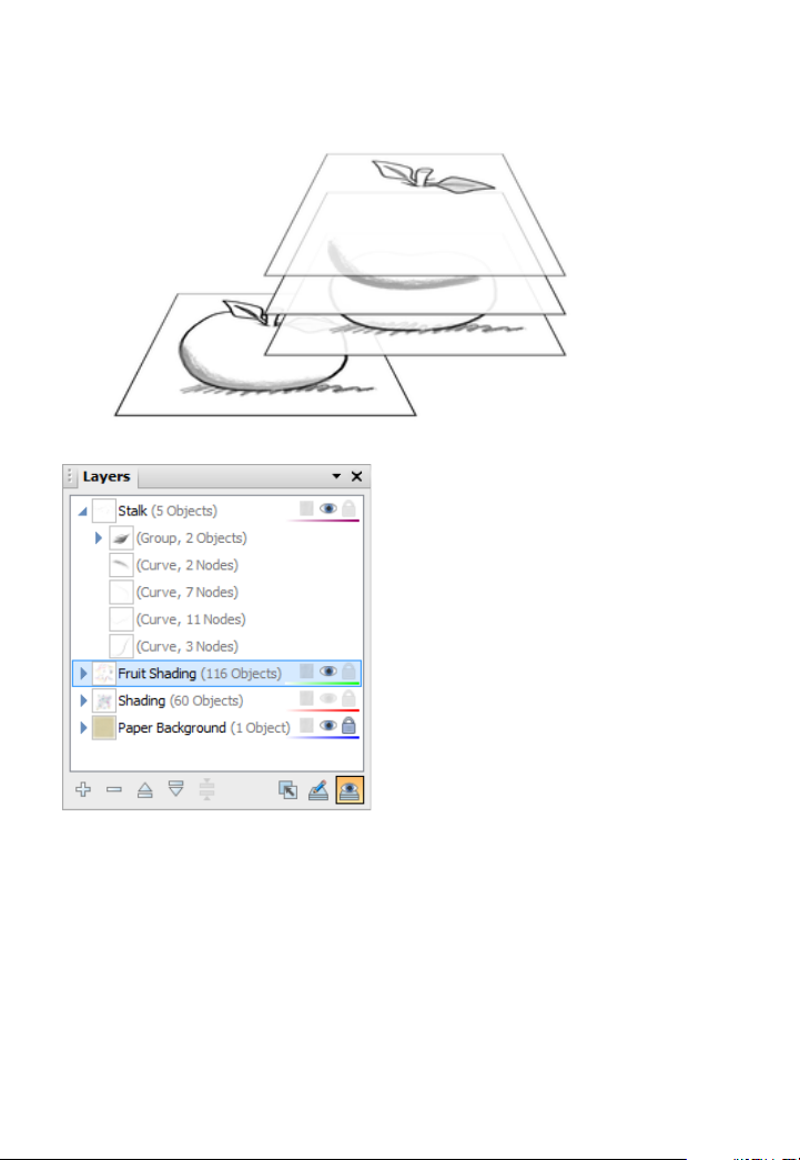
84 Working with Objects
Each layer is situated along with
any lower layer on the page. You
You can think of layers as transparent sheets of paper upon which you
can draw your objects.
other layers (if present) within a
stack on the Layers tab—the
uppermost layer is applied over
can also expand each layer entry
for a tree view of objects
associated with that layer (see
the Stalk layer opposite). Each
object entry can be clicked to
select the object in your
workspace.
In order to create a new object on a particular layer, you'll first need to
"activate" (select) that layer.
To select a particular layer:
• Click a layer name in the Layers tab.
Page 90

To add a new layer:
Working with Objects 85
• In the Layers tab, click the
Add Layer button to add a new
layer above the currently selected layer.
To rename a layer:
• To rename a layer to something more meaningful, click on the
selected layer's name and type to add your new name (you can also
make an insertion point to edit the existing text).
To delete a layer:
• In the Layers tab, select the layer’s name and click the
Delete
Layer button.
If you delete a layer, all of the objects on it are lost! So if you want to
keep any of them, move them to another layer first.
You can move layers up or down in the stacking order to place their
objects in front or behind those on other layers, move objects to specific
layers, and even merge layers.
To move a layer in the stacking order:
• Drag the selected layer to a new position in the layer stack.
Remember that objects on layers are drawn in the order in which the
layers were initially added to the Layers tab. Put another way: the
bottom layer in the Layers tab stack is drawn first then the second
bottom, third bottom etc. A background layer should be the bottom
layer in the Layers tab stack.
Page 91

86 Working with Objects
Layer Properties
Layer properties allow you to assign paper textures, make layers
invisible/visible, and/or locked/unlocked.
See Studio: Layers tab in DrawPlus Help for more details.
Managing objects on layers
A useful feature of the Layers tab is that you can see objects or even
groups of objects, under the layer on which they were created. This gives
you the option of selecting an object or group from the tab as opposed to
from the page itself. Groups and individual objects can be named,
allowing you to more easily locate them in the Layers tab, which in turn
locates them in the workspace for you.
To add objects to a particular layer:
• When drawn, objects are added to the selected layer
automatically. This is why it is a good idea to check which layer
you are currently working on!
To select an object on a layer:
1. On the Layers tab, click the
Expand icon on the chosen layer entry to
reveal all associated objects.
Page 92

Working with Objects 87
This tree view greatly improves the ability to select and manage nested
objects in more complex drawings. It's also great for visualizing your
object order.
2. Click the object entry in the tab. It will become highlighted and
selected on your page.
Trouble locating your named object or group? Search for it by using
Find Object on the Edit menu.
To move an object to another layer:
• Right-click the object in the workspace, and choose Move Object
to Layer. From the Move To Layer dialog, select the specific
destination layer, and click OK.
To hide/show an object on a layer:
• Right-click the object in the Layers tab (or multiple objects via
Ctrl-click), and select Visible. To show again, click the
displayed on the object entry.
icon
Cutting up objects
It is possible to cut any object (or picture for that matter) by using
the Knife Tool. You can cut along a freeform or straight line drawn
across your object(s), leaving you with separate fragments of the
original.
Page 93

88 Working with Objects
freeform cut
(using Bump profile)
straight line cut
To cut selected objects (freeform or straight line):
1. Select the
Knife Tool on the Drawing toolbar's Vector Edit
flyout.
2. (Optional) Use Smoothness on the tool's context toolbar to set how
regular the freeform cutting line is—click the right arrow and drag
the slider right for increasing smoothness.
3. (Optional) By default, you'll get a straight cutting profile, but for
regular-shaped cuts, pick a Cutting Profile from the context toolbar.
Page 94

Working with Objects 89
DrawPlus lets you take a "virtual"
adding to
4. Using the cursor, drag a freeform line across any object(s) you
would like to split (unselected objects on which the line traverses
will not be split). Instead, press the Shift key as you drag for a
straight line.
5. Hover over, then click to remove the unwanted cut area(s).
- or -
With the Pointer Tool, drag the newly split fragments apart instead.
Erasing and adding to objects
eraser to your drawing, letting you
remove portions of your selected
object(s) on an individual layer or
across multiple layers.
The flip side of erasing is "
"
(i.e., augmenting), a technique to add
or "grow" a vector objects'
boundaries—great for reshaping an
existing object.
Page 95

90 Working with Objects
To erase portions of a selected object:
1. Select the
Erase Tool on the Drawing toolbar's Vector Edit
flyout.
2. (Optional) From the context toolbar, choose a Nib style (circle,
square, or diamond) and/or set a Width to define the erase width
that will be cut.
3. Position the
cursor, and drag over an object boundary (or
within an object). You'll see the area to be erased being drawn
temporarily (use the Ctrl key to redefine the erase area while
drawing).
4. Release the mouse button to erase the area drawn.
To add to a selected object:
1. Select the
Freeform Paint Tool on the Drawing toolbar's
Vector Edit flyout.
2. (Optional) From the context toolbar, choose a Nib style (circle,
square, or diamond) and/or set a Width which will be drawn.
3. Position the
cursor over the object and drag over an object
boundary (or within the object). You'll see shading which represents
the area to be added. (You can use the Ctrl key to redefine the
painted area while holding down the mouse button).
4. Release the mouse button to reshape the object to include the newly
drawn area.
Page 96

Fills, Lines,
Colours, and
Transparency
Page 97

92 Fills, Lines, Colours, and Transparency
Setting fill properties
Any closed shape, such as a closed curve or QuickShape, or text has an
interior region that can be filled. The fill type can be solid, gradient,
bitmap or plasma or vector.
Fill types fall into several basic categories, illustrated above:
• Solid fills, as their name implies, use a single colour.
• Gradient fills provide a gradation or spectrum of colours between
two or more "key" colours. Mesh fills work like gradient fills but
with a more complex fill path.
• Bitmap and Plasma fills apply bitmapped images or patterns to
the object, each with unique properties. Think of bitmap fills as
named “pictures” that fill shapes. Plasma (or “fractal”) fills use
randomized patterns, useful for simulating cloud or shadow effects.
• Vector fills are similar to bitmaps but apply repeating patterns,
shapes or images such as shading or hatching to the object. Like
bitmaps, vectors are also named "images" but the fill is based on coordinates which define where lines are placed.
Solid colours
Applying a fill is easy, whether you’re selecting a colour from the Colour
tab or the Swatch tab.
Page 98

Fills, Lines, Colours, and Transparency 93
The Colour tab has several models available from a drop-down list—
HSL Colour Wheel (shown), HSL Colour Box, HSL Sliders, RGB Sliders,
RGB Sliders (Hex), CMYK Sliders and Tinting.
(A) Line/Fill swatches, (B) Colour Picker, (C) Colour Model, (D) Hue wheel,
(E) Saturation/Lightness triangle.
On the HSL Colour Wheel, the small circles shown in the wheel and
triangle indicate the current setting for hue and saturation/lightness,
respectively. Drag either circle around to adjust the values.
The Line/Fill swatches on the tab govern whether the selected colour is
applied as a line colour, solid fill, or both simultaneously.
By comparison, the Swatch tab hosts a vast array of preset colour
swatches for solid, gradient, plasma, vector and bitmap fills. Swatches
are stored in palettes which can be managed from within the tab. You
can even create your own palettes and palette categories.
Page 99

94 Fills, Lines, Colours, and Transparency
(A) Line/Fill swatches, (B) Document Palette, (C) Standard and themed
palettes, (D) Gradient palettes, (E) Bitmap palettes, (F) Vector palettes, (G)
Current palette.
CMYK operation
If you intend to create professional CMYK output to PDF or image, you
can optionally create a CMYK drawing from scratch (see p. 13). Your
drawing, in a CMYK colour space, can be designed using CMYK colours
(instead of RGB colours) either using:
• CMYK Sliders. (Click the colour model drop-down list on the
Colour tab.)
- or -
• Standard CMYK Palette. (Click the Palettes button on the Swatch
tab.)
Page 100

Fills, Lines, Colours, and Transparency 95
Applying colour
To apply a solid fill colour via the Colour tab:
1. Select the object(s) and display the Studio's Colour tab.
2. Click the Line/Fill Swatch at the top-left of the tab so the Fill Swatch
appears in front of the Line swatch.
This defines where the colour will be applied. Alternatively, apply
colour to both line and fill simultaneously by clicking
the swatch.
3. (Optional) Choose a colour model from the drop-down list.
Link on
4. Select a colour from the display.
To apply a solid fill colour via the Swatch tab:
1. Select the object(s) and display the Studio's Swatch tab.
2.
Set the Line/Fill Swatch at the top-left of the tab so the Fill
Swatch appears in front of the Line Swatch.
 Loading...