

Page 1
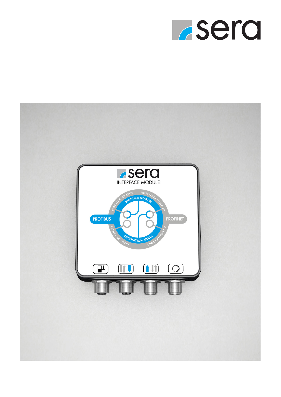
TECHNICAL MANUAL
PROFIBUS
INTERFACE MODULE
TRANSLATION OF ORIGINAL TECHNICAL MANUAL EN
Page 2
INTRODUCTION
NOTE
Keep the operating manual for future use!
ATTENTION
Subject to technical modifications!
About this instructions
Special notes in these instructions are marked with text and danger symbols.
NOTE
Notes or instructions that faciliate work and ensure a safe operation.
ATTENTION
The non-observance of these safety instructions can result in malfunctions or material damages.
WARNING
The non-observance of these safety instructions can lead to material damages and personal injuries.
Quality notes
The sera quality management and quality assurance system is certified in accordance with DIN EN ISO 9001:2015.
The sera product complies with the applicable safety requirements and accident prevention regulations.
2 www.sera-web.com
Page 3

CONTENTS
SAFETY INSTRUCTIONS ............................................................................................................. 4
Personnel qualification and training .............................................................................................................................. 4
Dangers in the case of non-observance of the safety instructions ...................................................................................... 4
Safety-conscious working ............................................................................................................................................ 4
Safety instructions for owner / operator ........................................................................................................................ 4
Improper operations ................................................................................................................................................... 4
Intended use .............................................................................................................................................................. 4
TRANSPORT / STORAGE ...........................................................................................................5
Transport .................................................................................................................................................................. 5
Storage ..................................................................................................................................................................... 5
PRODUCT DESCRIPTION ............................................................................................................ 6
Type plate ................................................................................................................................................................. 6
Accessoires ............................................................................................................................................................... 6
TECHNICAL DATA ......................................................................................................................7
Electrical data ............................................................................................................................................................ 7
Ambient conditions ..................................................................................................................................................... 7
Dimensions ................................................................................................................................................................ 7
ELECTRICAL CONNECTIONS .....................................................................................................8
Installation example / bus diagram ............................................................................................................................ 10
Stub cables ............................................................................................................................................................. 11
Bus cable ................................................................................................................................................................ 11
COMMISSIONING ..................................................................................................................12
OPERATION ............................................................................................................................ 13
LED operation indicators ........................................................................................................................................... 13
Operation window ................................................................................................................................................... 13
Operating Modes .................................................................................................................................................... 14
Modules ................................................................................................................................................................. 14
Explanation of the modules ....................................................................................................................................... 14
PROFIBUS acyclic data exchange .............................................................................................................................. 14
Modules / Input ....................................................................................................................................................... 15
Modules / Output .................................................................................................................................................... 16
Settings (parameters) ................................................................................................................................................ 16
Data from module to the master ................................................................................................................................. 23
MESSAGE ...............................................................................................................................29
Diagnostics signals ................................................................................................................................................... 29
Error message.......................................................................................................................................................... 29
MAINTENANCE / DECOMMISSIONING / DISPOSAL ................................................................ 30
Maintenance and cleaning ........................................................................................................................................ 30
Decommissioning ..................................................................................................................................................... 30
Disposal .................................................................................................................................................................. 30
www.sera-web.com 3
Page 4

SAFETY INSTRUCTIONS
SAFETY INSTRUCTIONS
WARNING
Before commissioning, installating and during operation of the sera dosing pump the respective regulations valid at the
place of installation are to be observed!
Compliance with these operating instructions and, in particular, the safety instructions, helps to:
■ Prevent danger to people, machines and the environment.
■ Increase reliability and service life of the product and the complete system.
■ Reduce repair costs and downtimes.
Personnel qualification and training
The personnel for operation, maintenance, inspection and installation must be suitably qualified for their tasks. The
owner must clearly define responsibility and supervision of the personnel.
If the personnel do not have the knowledge required, then personnel is to be trained and instructed correspondingly.
Such training can be provided by the manufacturer / supplier upon order of the owner. In addition, the owner has to
ensure that personnel have understood the operating instructions completely.
Dangers in the case of non-observance of the safety instructions
Non-observance of the safety instructions can result in hazards both for persons as well as for the environment and the product,
and can, for example, cause the following hazards:
■ Failure of important functions of the product.
■ Failure of prescribed methods for maintenance and repair.
■ Danger to people from electrical, mechanical and chemical influences.
Safety-conscious working
The safety instructions shown in this operating manual, the existing national accident prevention regulations and any internal
working, operating and safety regulations of the owner must be observed.
Safety instructions for owner / operator
Danger caused by electrical energy is to be avoided.
Improper operations
Operating safety of the supplied product is only guaranteed if the product is used as intended, according to the
descriptions in Chapter „Intended use“ of these operating instructions.
Intended use
The sera product is only to be deployed according to the intended purpose stated in the product description and the
acceptance test certificate.
If the product is to be used for other applications, then the suitability of the product for the new operating conditions
must be discussed with sera beforehand!
Criteria for operation in accordance with the intended use:
■ Operating conditions at the place of installation.
■ Voltage supply.
4 www.sera-web.com
Page 5

TRANSPORT / STORAGE
General
sera products are checked for perfect condition and function previous to shipment.
Check for transport damage immediately after arrival of goods. If damage is found, this is to be reported immediately to the
responsible carrier and the manufacturer.
Storage
An undamaged packaging protects the unit during storage and should only be opened when the product is installed.
Proper storage increases the service life of the product and includes prevention of negative influences such as heat, moisture,
dust, chemicals etc.
The following storage specifications are to be obsered:
■ Storage place: cool, dry, dustfree and slightly ventilated
■ Storage temperature and relative air humidity see Chapter „TECHNICAL DATA“.
■ The maximum storage time for the standard packaging is 12 months.
If these values are exceeded, metal products should be sealed in foil and protected from condensation water with a suitable
desiccant.
Do not store solvents, fuels, lubricants, chemicals, acids, disinfectants and similar in the storage room.
www.sera-web.com 5
Page 6
PRODUCT DESCRIPTION
107
The INTERFACE MODULE must only be used as communication interface between a controllable sera dosing pump and a
PROFIBUS network.
A proprietary sera protocol is used for the internal communication between INTERFACE MODULE and dosing pump.
NOTE
The sera dosing pump PROFIBUS option is integrated in the network via the device master data (DMD) file which must be
integrated in the development environment. This file contains the characteristics of the pump and information for the communication capability.
The DMD file can be downloaded by scanning the QR code (see type plate) or directly from the sera website www.
sera-web.com.
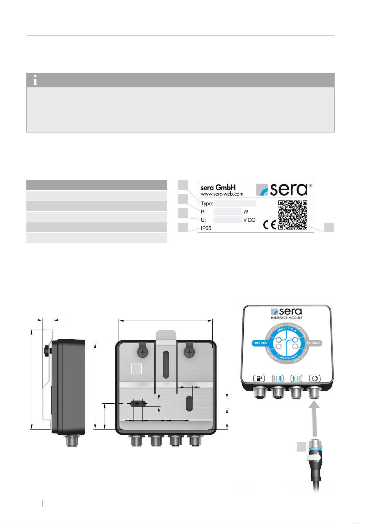
Type plate
The INTERFACE MODULE is provided with a type plate at the factory.
The information on the type plate is explained below.
No. Designation
1 Type
2 Max. power consumption
3 Supply voltage
4 Protection rating
5 QR code (for the DMD file)
Accessoires
The supply includes the following accessories:
■ Wall mount (1)
■ Sensor cable (2)
~12
100
1
2
3
4
5
6 www.sera-web.com
93
28
1
7
7
252510
23 10
2
Page 7
TECHNICAL DATA
Electrical data
109
113
50
M12 x 1
102
M12 x 1
~ 43
35
TECHNICAL DATA
PROFIBUS interface
Transmission rate
Supply voltage
Max. power consumption
PROFIBUS DP-V1 (slave)
GSD File sera sera0FA2.gsd
9.6/19.2/45.45/93.75/187.5/500 kbit/s
1.5/3/6/12 Mbit/s
Automatic baud rate detection
24 V DC
1 W
Ambient conditions
Max. height above sea level 1000 m
Max. relative humidity 90%
Protection rating IP65
Electrical protection class III
Ambient temperature 0 °C to 40 °C
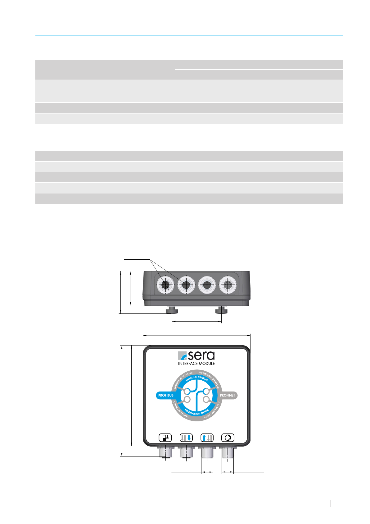
Dimensions
M12 x 1
35
~ 43
102
113
50
109
M12 x 1
M12 x 1
www.sera-web.com 7
Page 8
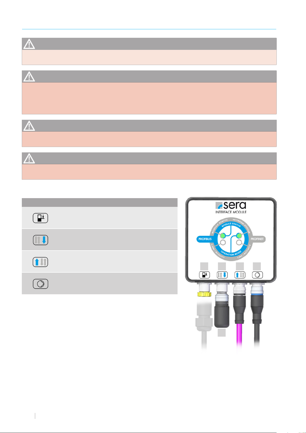
ELECTRICAL CONNECTIONS
ATTENTION
The electrical connection must be made by qualified personnel in compliance with the local regulations.
WARNING
Ensure absence of voltage of all cables and devices for the installation of electrical components!
Contact with stripped wires or live components can result in serious injuries or even death.
Any short-circuit can cause severe and expensive damage to the assemblies.
WARNING
Damaged cables should always be replaced!
WARNING
In order to guarantee the IP65 protection rating, all unused connections should be provided with a blanking plug.
Interface Assignment Function
1
2
3
4
no Y-connector necessary
*
Level
connection
PROFIBUS
Output *
PROFIBUS
Input *
Pump
connection
8-pole
5-pole
5-pole
8-pole
Pre-alarm and dry running protection
Connection to the
PROFIBUS network or
terminating resistor (5)
Connection to the
PROFIBUS network
Data transfer between
pump and INTERFACE
MODULE
1 2 3 4
5
8 www.sera-web.com
Page 9
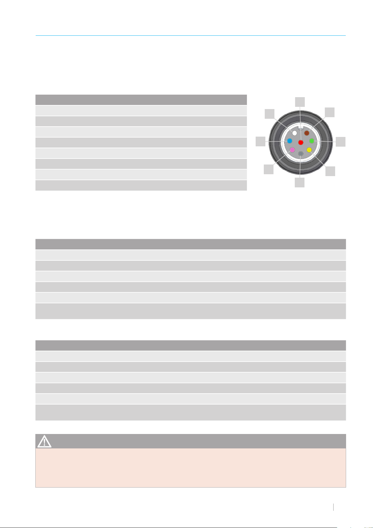
The field bus box modules are connected via the supplied connection cable.
The INTERFACE MODULE has a socket and a plug, whereby no Y-connector is necessary.
The supply voltage (+5 V DC) for the terminating resistor is only applied on the socket.
The terminating resistor is only available as plug connector.
Level connection (1)
ELECTRICAL CONNECTIONS
Pin Wire colour Function (factory setting)
Pin 1 WH (white) not assigned
Pin 2 BN (brown) not assigned
Pin 3 GN (green) not assigned
Pin 4 YE (yellow) not assigned
Pin 5 GY (grey) not assigned
Pin 6 PK (pink) Pre-alarm level
Pin 7 BU (blue) Dry run
Pin 8 RD (red) GND
The inputs can be switched using a floating contact signal.
Pre-alarm and dry running are set to normally open floating contacts at the factory.
The sockets of the connections are A-coded and the assignations of the functions are symbolically labelled.
WH
BU
PK
PROFIBUS output (2)
Pin No. Signal Description
Pin 1 VP +5 V supply for terminating resistor
Pin 2 A-line Negative RxD/TxD
Pin 3 GND bus Data ground
RD
BN
GN
YE
GY
Pin 4 B-line Positive RXD/TxD
Pin 5 Shield Not connected internally, connected internally with PROFIBUS cable with shield
Thread Cable shield Must be connected externally with PE via cable filter according to PROFIBUS
standard
PROFIBUS input (3)
Pin No. Signal Description
Pin 1 NC NC
Pin 2 A-line Negative RxD/TxD
Pin 3 GND bus Data ground.
Pin 4 B-line Positive RXD/TxD
Pin 5 Shield Not connected internally, connected internally with PROFIBUS cable with shield
Thread Cable shield Must be connected externally with PE via cable filter according to PROFIBUS
standard
ATTENTION
The M12 socket is inversely coded and has 5 pins. Pin 1 is 5 V DC and Pin 3 is GND for the active terminating resistor.
These must never be used for any other functions as this can result in destruction of the device.
Pin 2 and Pin 4 carry the data of the PROFIBUS communication. These must never be reversed otherwise the communication is disrupted. Pin 5 is the shield that is not internally connected to the module.
www.sera-web.com 9
Page 10

ELECTRICAL CONNECTIONS
Anschluss Pumpe (4)
Pin No. Function
Pin 1 +24 V supply voltage
Pin 2 Communication IM1
Pin 3 Communication IM2
Pin 4 not assigned
Pin 5 Communication IM3
Pin 6 Pre-alarm level
Pin 7 Dry run -
Pin 8 GND
Installation example / bus diagram
All devices are connected in a bus structure (line).
Up to 32 nodes (master or slaves) can be networked within one segment.
The first and the last device must be provided with a terminating resistor. The bus segments are connected to the overall network
with repeaters (amplifiers), but remain electrically isolated. Up to maximum 126 nodes (including repeaters) can be connected
within the overall network.
The bus nodes are identified by the bus address. Each address must be unique and may only be assigned once.
NOTE
The minimum cable length between the individual nodes must be at least 1 m for transmission rates of more than 1.5 Mbit/s.
It must be ensured for the cable installation that the PROFIBUS cable does not run parallel with other live cables.
Master
Terminating resistor
Slave
Slave
Slave
Slave
Slave Slave Slave Slave
Slave Slave Slave
Repeater
10 www.sera-web.com
Page 11

Stub cables
ELECTRICAL CONNECTIONS
Stub cables (2) (with Y or T distributing piece) are branches from the main bus line (1)
to the node.
Stub cables are never allowed if the transmission rates
exceed 1.5 Mbit/s. Stub cables may be used for transmission rates of less than or equal to 1.5 Mbit/s, if the
limit values stated in the table are not exceeded.
Transmission rate Total of stub cables *
> 1.5 Mbit/s none
1.5 Mbit/s 6.7 m
500 kbit/s 20 m
187.5 kbit/s 33 m
93.75 kbit/s 100 m
19.2 kbit/s 500 m
* Total of all stub cables within a segment for PROFIBUS cable
of 30 pF/m
The maximum cable length depends on the transmission
rate. For transmission rates greater than 1.5 Mbit/s, a
minimum cable length of 1m between two nodes is recommended.
Transmission rate Maximum cable length
> 1.5 Mbit/s 100 m
1.5 Mbit/s 200 m
1
2
500 kbit/s 400 m
187.5 kbit/s 1000 m
93.75 kbit/s 1200 m
45.45 kbit/s 1200 m
19.2 kbit/s 1200 m
9.6 kbit/s 1200 m
Bus cable
Cables with the following specifications must exclusively be used for new installations:
■ Characteristic impedance 135…165 ohm (resistance for high-frequency signals)
■ Capacitance <30 pF/m
■ Loop resistance 110 ohm/km
■ Wire diameter 0.64 mm
■ Wire cross section> 0.34 mm²
www.sera-web.com 11
Page 12
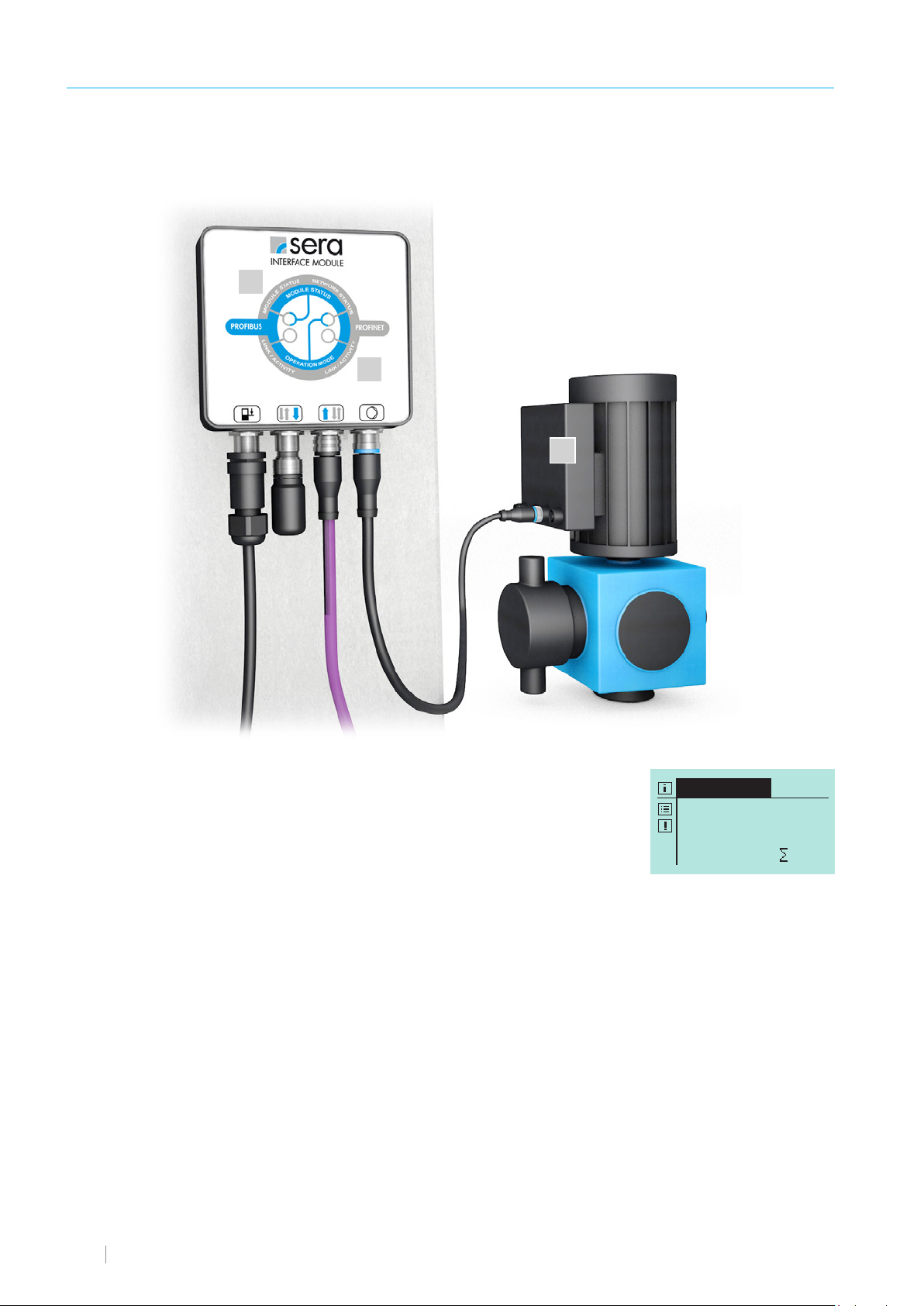
COMMISSIONING
INTERFACE
Manual
100.0 % freq.
0 N
■ Disconnect voltage.
■ Connect INTERFACE MODULE (1) to the sera pump (2) (see „Electrical Connections). Observe earthing.
3
1
2
■ Apply voltage.
■ Pump starts.
■ Module status (3) lights green.
■ The “INTERFACE” operating mode must be enabled and can be selected for operating
modes.
■ Set the address for PROFIBUS (see chapter „Settings (parameters)“).
12 www.sera-web.com
Page 13
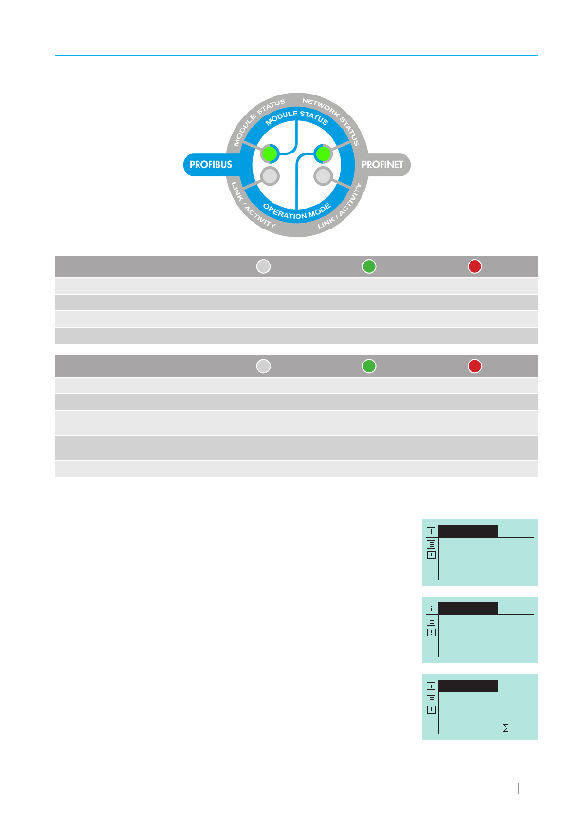
LED operation indicators
INTERFACE
Manual
100.0 % freq.
0 N
INTERFACE
Bus fail safe
INTERFACE
Bus offline!
OPERATION
MODULE STATUS
Operational readiness x
Diagnostics notification is pending flashes
Module error x
not initialised x
OPERATION MODE
On-line, data exchange x
On-line, ready flashes
Parametrisation error
PROFIBUS configuration error
not initialised x
off green red
off green red
flashes once f
or a short time
flashes twice
for a short time
Operation window
INTERFACE MODULE is initialised.
No BUS/NETWORK connection is established or there is no data exchange.
BUS/NETWORK connection established.
Data exchange is present.
No operating mode has been selected in the PUMP_CONTROL module.
No valid process data exist.
Communication available.
www.sera-web.com 13
Page 14
OPERATION
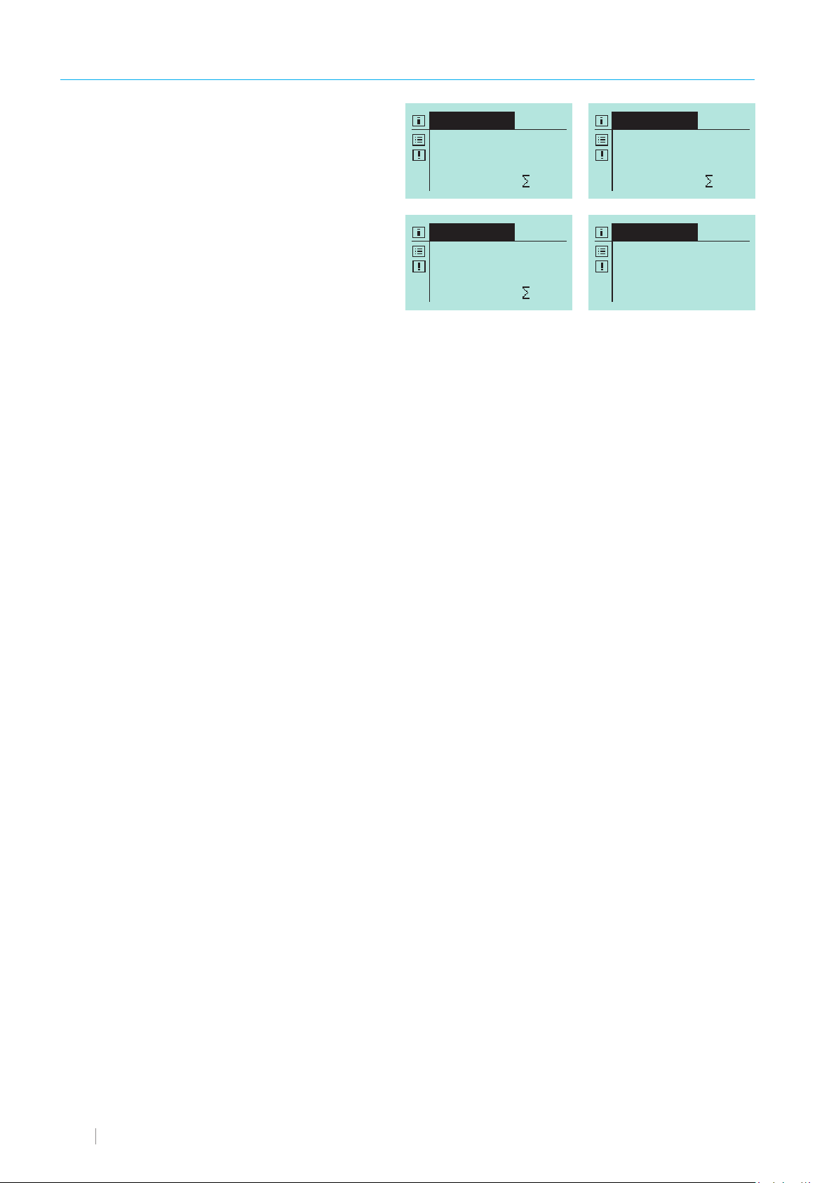
INTERFACE
Manual
100.0 % freq.
0 N
INTERFACE
Impulse
100.0 % freq.
0 N
Memory: 0
INTERFACE
Analog
0.0 % freq.
0 N
E2: 0.00 mA
INTERFACE
Batch
0.0 % freq.
V: 0N R: 0N
Operating Modes
The following operating modes are possible in interface operation:
■ Manual
■ Impulse
■ Analog
■ Batch
Modules
Thanks to use of the modular design, every sera dosing pump connected to the INTERFACE MODULE can be parametrised according to their own requirements. It is possible to adapt the amount of process data precisely to the needed task.
Explanation of the modules
Input data The modules with the "CONTROL" ending are modules with process data sent to the pump. The pump can
be controlled and adjusted using these.
Output data The modules with the "STATE" ending are modules with process data received from the pump. These return
the status of the pump.
The modules can be used individually depending on the application and desired operating mode. However, the „PUMP_CONTROL“ module must always be used for the control of the pump via the network as the operating mode is set here.
The pump can also be monitored for non-interface operating modes using the State modules.
All functions that can also be set using the hand-held control unit can be parametrised via the modules. Only timer operation
cannot be adjusted.
The Module Status LED lights continuously after the initialisation of the module by the pump.
The Operation Mode LED indicates the network status. It lights green continuously when process data are being exchanged with
a controller. It flashes green if the module is connected to a controller but no process data are being exchanged.
PROFIBUS acyclic data exchange
All modules can be addressed in Slot 1. The index number corresponds to the respective module number from the module table.
If data are read acyclically, the size of the data to be read must be specified using the length parameter of the DP-V1 request.
If more data are requested than the module provides, the INTERFACE MODULE only returns the data that are available in the
respective module. If fewer data than are available are requested, the module only returns data of the requested data quantity.
The module does not check the specified data length for acyclic requests.
If a greater data quantity than available is specified in PROFIBUS or PROFINET, the data cannot be accessed and the device
retains the last valid data.
14 www.sera-web.com
Page 15

OPERATION
Modules / Input
PUMP_CONTROL
This module is always necessary for the control of the pump irrespective of operating mode. The External Stop Bit that is valid
in all operating modes can be set with this module.
Other functions are the setting of the operating mode, reset of the totaliser, acknowledgement of alarms, stroke control for motor
pumps. If a valid interface operating mode is selected and the pump is not in interface operation, it automatically switches to
interface operation.
MANUAL_CONTROL
Adjustment of the stroke frequency / litre capacity in manual mode.
The operating mode in PUMP_CONTROL must be set to Manual Interface.
PULSE_CONTROL
A pulse for executing a stroke can be sent to the pump using the pulse bit. The pulse is detected during a flank change from
0 to 1. Furthermore, the functionalities of pulse parameters are shown. The stroke frequency / litre capacity can be set using
other input data.
ANALOG_CONTROL
Used for operation of the pump using analogue signal. The functionality of analogue parameters is shown via the input data.
A module for parametrisation of the analogue input is required for the operation.
BATCH_CONTROL
Start of a batch, reset of the remaining batch and changeover between „normal“ or „analogue“ batch possible.
Otherwise the batch quantity in strokes / litres and the stroke frequency / litre capacity can be set.
INPUT1_CONTROL, INPUT2_CONTROL, INPUT3_CONTROL
Setting of the inputs analogously to the menu.
OUTPUT1_CONTROL, OUTPUT2_CONTROL
Settings of the outputs analogously to the menu.
A_OUTPUT_CONTROL
Settings of the analogue output analogously to the menu.
MBE_CONTROL, SPEEDLIMIT_CONTROL, SLOWMODE_CONTROL, DOSING_CONTROL,
DEARIATION_CONTROL, LEVEL_CONTROL
Settings analogously to the Extras menu.
TIME_CONTROL
Setting of the system time of the pump.
CALIBRATION_CONTROL
The litre capacity of the pump can be calibrated with this module.
FLASH_CONTROL
Settings for the SD card.
DIACHANGE_CONTROL
Module for performing a diaphragm change. Analogous to the DIACHANGE_STATE status request.
www.sera-web.com 15
Page 16

OPERATION
PARAMETER
Adresse 001...125
Modules / Output
PUMP_STATE
Statuses of the pump. All operating modes of the pump are displayed here. Even if the pump is not in the Interface mode.
FLOW_STATE
Current delivery rate of the pump in litres / hour or strokes. Valid across operating modes.
COUNTER_STATE
Totaliser of the pump.
BATCH_STATE, IMPULS_STATE, ANALOG_STATE
Pump information of the respective set operating mode. No module exists for the Manual operating mode as there is no information except the current delivery rate.
INPUT1_STATE, INPUT2_STATE, INPUT3_STATE, OUTPUT1_STATE, OUTPUT2_STATE
Information of the inputs / outputs analogous to the associated CONTROL modules.
A_OUTPUT_STATE
Current analogue output current.
CALIBRATION_STATE
Information during a calibration.
PUMP_INFO_STATE
General pump information, Dependent on the pump type.
ALARM_STATE
Display of the error signals of the pump. Active bit means error is present.
Settings (parameters)
The module is sent using the PROFIBUS address 126. Only the „SSA“ function is activated
with this address and a new address can be allocated via the network.
The address range 1-125 can also be set here if the addressing via SSA is not desired.
16 www.sera-web.com
Page 17

OPERATION
The control and parametrisation of the pump are performed using modules that are described in the following table:
No. Module Name Data type Function Comment
1 PUMP_CONTROL Byte 1 Bit definition: Must always be implemented to select the ope-
0. 0. External Stop ON/OFF
1-3 Operating mode
000 Fail Safe
001 Manual interface
010 Impulse interface
011 Analog interface
100 Batch interface
4. Reset Counter
5. Reserved
6. Acknowledge alarm message
7. Stroke control
rating mode.
If a valid interface operating mode is selected
and the pump is not in interface operation, it
automatically switches to interface operation.
Then no other operating mode can be selected.
The current stroke counter (not calibrated) and
litre counter are reset using Reset Counter. The
counter is maintained at 0 if the bit is set.
Acknowledge alarm message using flank change to 1.
Stroke control only has an influence for motor
pumps
0 ► Auto
1 ► Stroke frequency
2 MANUAL_
CONTROL
3 IMPULSE_
CONTROL
1. Float not calibrated:
0.0 - 100.0%
calibrated
0.000 l - max. litres/hour
Byte 1 Bit definition:
0. 0. Pulse
1. 1. Pulse memory ON/OFF
2-3 Pulse mode
00 Divisor
01 1/1
10 Multiplier
11 Proportional
Float 2 Pulse Flow
not calibrated:
0.0 - 100.0%
calibrated:
0.000 l - max. litres/hour
Float 3 Pulse Upper Flow
not calibrated:
0.0 - 100.0%
calibrated:
0.000 l - max. litres/hour
The decimal position of the percentage value is
truncated for motor pumps.
Specification in litres with up to three decimal
places for calibrated pump.
Word 4 Pulse factor / pulse limit The value means pulse limit if proportional pulse
0-999
mode is selected.
www.sera-web.com 17
Page 18

OPERATION
No. Module Name Data type Function Comment
4 ANALOG_
CONTROL
5 BATCH_CONTROL Byte 1 Bit definition: The remaining batch quantity is zeroed while
Byte 1 Bit definition: INPUT2_CONTROL or INPUT3_CONTROL
0-2 Analogue signal
00 0-20 mA
01 4-20 mA
10 Standardised
Byte 2 Analogue I1 Bytes 2-5 are only used standardised for ana-
0-200
Byte 3 Analogue Frequency f1
0-100%
Byte 4 Analogue I2
0-200
Byte 5 Analogue Frequency f2
0-100%
0. Start Batch
1. Reset of the remaining
batch
2. Normal batch / Analogue
batch
Float 2 Batch Volume
0.000 l - dependent on pump
Float 3 Batch Flow
not calibrated:
0.0 - 100.0%
calibrated:
0.000 l - max. litres/hour
must be set as analogue input for the analogue
operation.
logue signal.
0= 0.0 mA
200= 20.0 mA
155= 15.5 mA
Bit 1 is set. Can also be used for cancellation of
a batch. Batch is also reset by setting External
Stop.
Two analogue inputs must be parametrised accordingly for Analogue Batch. The batch can be
started either by Bit 0 in Batch Control or by the
digital input.
Batch Flow = 0.0 can be set to pause a batch.
The speed can be varied during a batch.
6 INPUT1_CONTROL Byte 1 Bit definition: The function of the INPUTS / OUTPUTS can be
0-3 Input function
0000 OFF
0001 External stop
0010 Venting
0011 Impulse
0100 Analogue changeover
0101 Recipe
0110 Start Batch
4. NC contact / NO contact
set in bus operation by using the respective module. Otherwise, the functionality on delivery is
applicable.
18 www.sera-web.com
Page 19

OPERATION
No. Module Name Data type Function Comment
7 INPUT2_CONTROL Byte 1 Bit definition: The function of the INPUTS / OUTPUTS can be
0-3 Input function
0000 OFF
0001 External stop
0010 Venting
0011 Impulse
0100 Analog 1
0101 Recipe
0110 Start Batch
0111 Batch quantity
1000 Batch output
4. NC contact / NO contact
8 INPUT3_CONTROL Byte 1 Bit definition: The function of the INPUTS / OUTPUTS can be
0-3 Input function
0000 OFF
0001 External stop
0010 Venting
0011 Impulse
0100 Analog 2
0101 Recipe
0110 Start Batch
0111 Batch quantity
1000 Batch output
4. NC contact / NO contact
9 OUTPUT1_
CONTROL
Byte 1 Bit definition: The function of the INPUTS / OUTPUTS can be
0-3 Output function
0000 OFF
0001 Operational
0010 Pump active
0011 Stroke signal
0100 Pre-alarm level
0101 Dry run
0110 Diaphragm rupture
0111 No flow
1000 Group signal
1001 Group fault
1010 Internal error
1011 Batch finished
4. NC contact / NO contact
set in bus operation by using the respective module. Otherwise, the functionality on delivery is
applicable.
set in bus operation by using the respective module. Otherwise, the functionality on delivery is
applicable.
set in bus operation by using the respective module. Otherwise, the functionality on delivery is
applicable.
www.sera-web.com 19
Page 20

OPERATION
No. Module Name Data type Function Comment
10 OUTPUT2_
CONTROL
11 A_OUTPUT_
CONTROL
12 MBE_CONTROL Byte 1 Bit definition:
Byte 1 Bit definition: The function of the INPUTS / OUTPUTS can be
0-3 Output function
0000 OFF
0001 Operational
0010 Pump active
0011 Stroke signal
0100 Pre-alarm level
0101 Dry run
0110 Diaphragm rupture
0111 No flow
1000 Group signal
1001 Group fault
1010 Internal error
1011 Batch finished
4. NC contact / NO contact
Byte 1 Bit definition:
0-1 Analogue output function
00 Analogue input
01 Remaining batch
10 Stroke frequency / litre
capacity
2. Reserved
3-4 Analogue output signal
00 0-20 mA
01 4-20 mA
10 Standardisation
Byte 2 Analogue output current 1 Bytes 2-5 are only used standardised for ana-
0-200
Byte 3 Analogue output percentage value
1
0-100%
Byte 4 Analogue output current 2
0-200
Byte 5 Analogue output percentage value
2
0-100%
0-1 MBE signal
00 OFF
01 NC contact
10 NO contact
Byte 2 Sensitivity
0-100%
set in bus operation by using the respective module. Otherwise, the functionality on delivery is
applicable.
logue signal.
0= 0.0 mA
200= 20.0 mA
155= 15.5 mA
20 www.sera-web.com
Page 21

No. Module Name Data type Function Comment
13 SPEEDLIMIT_
CONTROL
14 SLOWMODE_
CONTROL
15 DOSING_
CONTROL
16 DEAERATION_
CONTROL
17 LEVEL_CONTROL Byte 1 Bit definition:
Byte 1 Speed limit
30-100%
Byte 1 Bit definition:
0-1 Suction stroke
00 100%
01 75%
10 50%
11 25%
Byte 1 Bit definition:
0-3 Sensor type
000 OFF
001 TYPE 8x9x.1
010 TYPE 801x.1
4. Warning / STOP
Byte 2 Fault strokes
1-100 strokes
Byte 3 Alarm limit Alarm limit only active for sensor TYPE 801x.1.
1-100%
Byte 1 Bit definition:
0. Start venting Start of the venting only for external control
1-2 Control
00 OFF
01 External
10 Interval
11 Automatic
Byte 2 Interval time
15-100 minutes
Word 3 Venting time
10-300 seconds
0-1 Pre-alarm
00 OFF
01 NC contact
10 NO contact
2-3 Dry run
00 OFF
01 NC contact
10 NO contact
OPERATION
www.sera-web.com 21
Page 22

OPERATION
No. Module Name Data type Function Comment
18 TIME_CONTROL Byte 1 Bit definition:
0. Set time The time is applied when changing the bit from
Byte 2 Day
1-31
Byte 3 Month
1-12
Byte 4 Year Year starting from 2000. 0 cor-
0-105
Byte 5 Hour MBE Change must be performed after setting
0-24
Byte 6 Minute
0-59
0 to 1.
responds to the year 2000.
16 corresponds to 2016. Input starting from
year 2000 possible.
the time to reset the timer.
The old time setting is retained if an invalid date
is transmitted.
19 CALIBRATION_
CONTROL
20 FLASH_CONTROL Byte 1 Bit definition:
21 DIACHANGE_
CONTROL
Byte 1 Bit definition: The calibration starts with the change of Bit 0
0. Start Calibration
1. Cancel Calibration
2. Save Calibration Value
3. Calibration ON/OFF
Word 2 Calibration strokes
1-9999 strokes
Byte 3 Calibration speed
1-100%
Float 4 Calibration result
0.000 - max. value in l
0. Signals ON/OFF
1. Operating data ON/OFF
2-3 Write period
00 1 minute
01 5 minutes
10 10 minutes
11 30 minutes
Byte 1 Bit definition: The change is started with the change of Bit 0
0. Start of the diaphragm change
1. Change completed
from 0 to 1. A valid value for the calibration
strokes and calibration speed must be present.
The calibration value is saved with the change
of Bit 2 from 0 to 1. A value greater than 0
must exist in Float 4 and the calibration must be
completed for this.
Using Bit 3, the calibration can be deactivated
for a calibrated pump by setting the bit to 1. The
control is then performed with specification of a
stroke frequency.
from 0 to 1. The change is completed with the
change of Bit 1 from 0 to 1.
22 www.sera-web.com
Page 23

Data from module to the master
No. Module Name Data type Function Comment
22 PUMP_STATE Byte 1 Bit definition:
0-3 Operation Mode
0000 Interface Operation Fail
Safe
0001 Manual interface
0010 Pulse interface
0011 Analogue interface
0100 Batch interface
0101 Manual
0110 Pulse
0111 Analogue
1000 Batch
1001 Reserved
1010 Timer
Byte 2 Pump State 2 Bit 1 changes from 0 to 1 for 160 ms after
0. Pump OFF/ON
1. Stroke signal
2. Group signal
present
3. Group fault present
4. Acknowledgement of error
message performed
5. Diaphragm change active
7. Pump calibrated No / Yes
23 FLOW_STATE Float 1 Current delivery rate
not calibrated:
0.0 - 100.0%
calibrated:
0.000 l - max. litres/hour
each performed stroke.
OPERATION
www.sera-web.com 23
Page 24

OPERATION
No. Module Name Data type Function Comment
24 COUNTER_STATE Float 1 Current delivered quantity
Not calibrated:
Strokes since switching on
or reset
Calibrated
Litres since switching on
or reset
Long 2
(4-byte)
Long 3
(4-byte)
Long 4
(4-byte)
Long 5
(4-byte)
25 BATCH_STATE Byte 1 Bit definition:
Float 2 Batch volume
Float 3 Batch speed
Float 4 Remaining batch quantity
26 PULSE_STATE Byte 1 Bit definition:
Word 1 Pulse Memory Registered pulses
Total delivered quantity
In litres, since delivery of the pump
Total number of strokes
In strokes, since delivery of the
pump
Operating hours
In hours, since delivery of the
pump
Diaphragm hours
In hours, since delivery or last
diaphragm change
0. Batch is being conveyed
Specification according to
BATCH_CONTROL or using analogue input
Specification according to
BATCH_CONTROL
0.001 l - max. batch volume
0. Pulse
1. Pulse memory
ON/OFF
2-3 Pulse mode
00 Divisor
01 1/1
10 Multiplier
11 Proportional
0-999
24 www.sera-web.com
Page 25

No. Module Name Data type Function Comment
27 ANALOGUE_STATE Byte 1 Bit definition:
0-2 Analogue signal
00 0-20 mA
01 4-20 mA
10 Standardised
Byte 2 Analogue I1
0-200
Byte 3 Analogue Frequency f1
0-100%
Byte 4 Analogue I2
0-200
Byte 5 Analogue Frequency f2 0= 0 mA
0-100%
Byte 6 Analogue Current
0-250
28 INPUT1_STATE Byte 1 Bit definition:
0-3 Input function
0000 OFF
0001 External stop
0010 Venting
0011 Pulse
0100 Analogue changeover
0101 Recipe
0110 Start Batch
4. NC contact / NO contact
5. set / not set
29 INPUT2_STATE Byte 1 Bit definition:
0-3 Input function
0000 OFF
0001 External stop
0010 Venting
0011 Pulse
0100 Analogue 1
0101 Recipe
0110 Start Batch
0111 Batch quantity
1000 Batch output
4. NC contact / NO contact
5. set / not set 5. Bit not applicable for analogue function.
150= 15.0 mA
200= 20.0 mA
The current at the active input is displayed.
OPERATION
www.sera-web.com 25
Page 26

OPERATION
No. Module Name Data type Function Comment
30 INPUT3_STATE Byte 1 Bit definition:
0-3 Input function
0000 OFF
0001 External stop
0010 Venting
0011 Pulse
0100 Analogue 1
0101 Recipe
0110 Start Batch
0111 Batch quantity
1000 Batch output
4. NC contact / NO contact
5. set / not set
31 OUTPUT1_STATE Byte 1 Bit definition:
0-3 Output function
0000 OFF
0001 operational
0010 Pump active
0011 Stroke signal
0100 Pre-alarm level
0101 Dry run
0110 Diaphragm rupture
0111 No flow
1000 Group signal
1001 Group fault
1010 Internal error
1011 Batch finished
4. NC contact / NO contact
5. set / not set
26 www.sera-web.com
Page 27

No. Module Name Data type Function Comment
32 OUTPUT2_STATE Byte 1 Bit definition:
0-3 Output function
0000 OFF
0001 operational
0010 Pump active
0011 Stroke signal
0100 Pre-alarm level
0101 Dry run
0110 Diaphragm rupture
0111 No flow
1000 Group signal
1001 Group fault
1010 Internal error
1011 Batch finished
4. NC contact / NO contact
5. set / not set
33 A_OUTPUT_STATE Byte 1 Analogue Out Current
0-200
0= 0 mA
150= 15.0 mA
200= 20.0 mA
OPERATION
34 CALIBRATION_
STATE
35 PUMP_INFO_STATE Float 1 MAX_FLOW
Byte 1 Bit definition:
0. Start Calibration
1. Cancel Calibration
2. Save Calibration
Value
3. Calibration ON/
OFF
4. Calibration active
5. Calibration finished
Word 1 Calibration Remain Strokes
0-999
Maximum delivery rate in l/h
Word 1 MAX_STROKE
Maximum stroke frequency in
strokes/minute
Word 1 SERA-CODE
0-65535
Long 1 SERIAL_NUMBER
0-999999
Byte 1 SW
vM01.xxx
Byte 1 HW The last three digits of the hardware and soft-
vHC01.xxx
ware versions are transmitted.
www.sera-web.com 27
Page 28

OPERATION
No. Module Name Data type Function Comment
36 ALARM_STATE Long 1
(4-byte)
Byte 1
Bit 0 Drive fault
Bit 1 Out of calibration range Bit 1 (only pumps with HLE)
Bit 2 Setpoint cannot be achie-
ved
Bit 3 Fault stroke sensor
Bit 4 No stroke detection
Bit 5 Reserved
Bit 6 Drive too slow
Bit 7 Reserved
Bit 8 Diaphragm rupture
Bit 9 Pre-alarm level
Bit 10 Dry run level
Bit 11 Mains voltage too high
Bit 12 Mains voltage too low
Bit 13 no flow, only for active
flow rate monitoring
Bit 14 Flow rate too low
Bit 15 Pulse memory overflow
Bit 16 Overtemperature, only
stepper motor pump
Bit 17 Service time exceeded
Bit 18 SD card fault
Bit 19 Analogue signal > 20 mA
Bit 20 Analogue signal < 4 mA
Bit 21 Analogue signal > 25mA
Bit 22 Reserved
Bit 23 Reserved
Bit 24 Reserved
Bit 25 Reserved
Bit 26 Reserved
Bit 27 Reserved
Bit 28 Reserved
Bit 29 Reserved
Bit 30 Reserved
Bit 31 Reserved
28 www.sera-web.com
Page 29

MESSAGE
Diagnostics signals
The sera INTERFACE MODULE has two diagnostics messages that are output in the network-specific protocol (PROFIBUS / PROFINET). A present message is indicated by flashing once for a short time of the Module Status LED. The messages can be read in
plain text using the diagnostics function of the Engineering tool.
The following messages can be generated:
■ PUMP_WARNING
There is a signal in the pump. The pump is still operational.
■ PUMP_ERROR
There is a fault in the pump. The pump is not operational.
■ ALARME_STATE
The module can be used to evaluate the error.
Error message
Error message Possible cause Corrective action
Disconnect voltage.
Connect module to pump.
Switch on voltage again.
Please contact the manufacturer.
Fault bus module
Fault bus module
Module has been removed from the pump
during operation.
Internal error of the communication
module.
www.sera-web.com 29
Page 30
MAINTENANCE / DECOMMISSIONING / DISPOSAL
Maintenance and cleaning
The INTERFACE MODULE is maintenance-free. Clean with a moist cloth. Rub dry afterwards.
ATTENTION
Do not use any solvents! These can attack the surfaces.
Decommissioning
■ Disconnect device from the power supply.
■ Detach electrical connections.
■ Take device out of operation.
ATTENTION
Only let the decommissioning be performed by authorised and qualified personnel.
Disposal
Dispose of correctly and comply with the currently applicable local regulations after shutdown and dismantling.
ATTENTION
Dispose of electronics separately!
30 www.sera-web.com
Page 31

www.sera-web.com 31
Page 32

FOLLOW US
sera ProDos GmbH
sera-Str. 1
34376 Immenhausen
Germany
Tel. +49 5673 999 02
Fax +49 5673 999 03
[email protected]
www.sera-web.com
is a registered trademark by sera GmbH.
®
TA05-00 EN 180228 sera
Subject to change without notice. sera accepts no liability for errors or misprints.
 Loading...