

Page 1
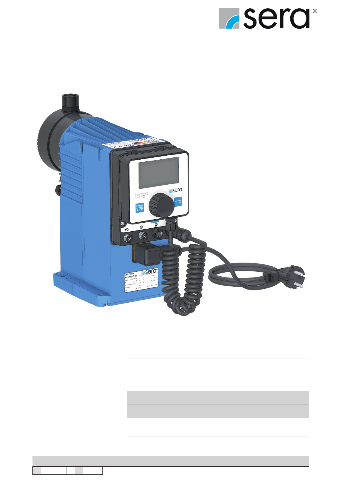
Stepper motor pump
®
iSTEP
Operating Instructions
iSTEP ®S 20
®
®
®
S 30
S 40
S 50
iSTEP
iSTEP
iSTEP
Manufacturer:
sera GmbH
sera-Straße 1
34376 Immenhausen
Germany
Tel.: +49 5673 999-00
Fax: +49 5673 999-01
[email protected]
www.sera-web.com
Translation of the original operating instructions!
TA 508 Rev. 00 en 11/2015
Subject to technical modications!
Keep the operating manual for future use!
Record the exact type and serial number here.
(can be read off the type plate on the pump)
Type :
Serial No. :
These data are important in the case of queries or for ordering spare and/or wear
parts and must always be stated.
www.sera-web.com
1
Page 2

Stepper motor pump
®
iSTEP
Operating Instructions
Content
1. General ....................................................................................................................................................... 4
1.1 General user information ...................................................................................................................... 4
1.2 Symbols and notes used in these operating instructions ..................................................................... 4
1.3 Notes attached to the product ..............................................................................................................4
1.4 Quality instructions ............................................................................................................................... 5
2. Safety instructions .................................................................................................................................... 5
2.1 Personnel qualication and training .....................................................................................................5
2.2 Dangers in case of inobservance of the safety instructions ................................................................. 5
2.3 Safety conscious working ..................................................................................................................... 5
2.4 Safety instructions for owner / operator ................................................................................................6
2.5 Safety instructions for maintenance, servicing and installation work ................................................... 6
2.6 Arbitrary modication and production of spare parts ............................................................................6
2.7 Improper operations .............................................................................................................................6
2.8 Intended use .........................................................................................................................................6
2.9 Operating conditions ............................................................................................................................7
2.10 Personal protection for maintenance and service .............................................................................. 7
2.11 Utilities/Lubricants ..............................................................................................................................7
2.12 Foreseeable misuse ........................................................................................................................... 8
2.12.1 Transport ....................................................................................................................................8
2.12.2 Assembly and installation ........................................................................................................... 8
2.12.3 Start-up ......................................................................................................................................8
2.12.4 Operation ...................................................................................................................................9
2.12.5 Maintenance/Repair ................................................................................................................... 9
2.12.6 Cleaning ..................................................................................................................................... 9
2.12.7 Shut-down ................................................................................................................................ 10
2.12.8 Disassembly ............................................................................................................................. 10
2.12.9 Disposal ...................................................................................................................................10
3. Transport and storage ............................................................................................................................ 11
3.1 General ............................................................................................................................................... 11
3.2 Storage ............................................................................................................................................... 11
4. Product description ................................................................................................................................12
4.1 Types ..................................................................................................................................................12
4.1.1 Type key ..................................................................................................................................... 12
4.1.2 Type plate ................................................................................................................................... 12
4.2 Materials ............................................................................................................................................. 13
4.3 Viscosity, pumped medium ................................................................................................................. 13
4.4 Noise measurement ...........................................................................................................................13
4.6 Delivery characteristic ........................................................................................................................14
4.6 Components of the diaphragm pump ................................................................................................. 15
4.7 Functional description ........................................................................................................................16
4.7.1 General ......................................................................................................................................16
4.7.2 Stroke mechanism with assembly pump .................................................................................... 16
4.7.3 Pump body ................................................................................................................................. 16
4.7.4 Suction / Pressure valve ............................................................................................................17
4.7.5 Diaphragm rupture monitoring device ....................................................................................... 17
4.7.6 Electronics with removable control element ............................................................................... 18
4.7.7 Automatic ventilation device (option) .......................................................................................... 19
4.7.8 Interface module (accessories) ................................................................................................. 19
4.7.9 Suction lances connection (accessories) ................................................................................... 19
5. Technical Data .........................................................................................................................................20
5.1 Output data .........................................................................................................................................20
5.3 Dimensions .........................................................................................................................................22
6. Assembly / Installation ............................................................................................................................24
7. Electrical connections ............................................................................................................................32
7.1 Mains power connection .....................................................................................................................32
7.2 Electrical interfaces ............................................................................................................................33
7.2.1 External control ..........................................................................................................................33
2
www.sera-web.com
Subject to technical modications!
TA 508 Rev. 00 en 11/2015
Page 3

Stepper motor pump
®
iSTEP
Operating Instructions
7.2.2 Flow monitoring and ow rate measurement .............................................................................35
7.2.3 Level Connection .......................................................................................................................35
8. Operation in Ex-zone ..............................................................................................................................36
9. Start-up ..................................................................................................................................................... 36
10. Operation ...............................................................................................................................................37
10.1 Controls ............................................................................................................................................ 37
10.2 Navigation ........................................................................................................................................38
10.3 Start-up (initial commissioning) ........................................................................................................38
10.4 LED-Betriebsanzeigen .....................................................................................................................39
10.5 Menü ................................................................................................................................................40
10.6 Operating modes .............................................................................................................................. 42
10.6.1 MANUAL operating mode ........................................................................................................43
10.6.2 IMPULSE operating mode .......................................................................................................43
10.6.3 ANALOGUE operating mode ...................................................................................................45
10.6.4 BATCH operating mode ...........................................................................................................47
10.6.5 TIMER operating mode ............................................................................................................ 53
10.7 Settings (parameters) ....................................................................................................................... 54
10.8 Inputs/outputs ................................................................................................................................... 55
10.8.1 Input 1 (digital) .........................................................................................................................56
10.8.2 Inputs 2 and 3 (digital/analogue) .............................................................................................. 57
10.8.3 Outputs 1 and 2 (digital) ........................................................................................................... 58
10.8.4 Analogue output ......................................................................................................................59
10.9 Extras ...............................................................................................................................................59
10.9.1 Slow mode ...............................................................................................................................59
10.9.2 Speed limit ...............................................................................................................................60
10.9.3 Dosing monitor ......................................................................................................................... 60
10.9.4 Diaphragm monitor ................................................................................................................... 61
10.9.5 Level ......................................................................................................................................... 62
10.9.6 Venting .....................................................................................................................................63
10.10 SYSTEM .........................................................................................................................................65
10.10.1 Language ...............................................................................................................................65
10.10.2 Display ...................................................................................................................................65
10.10.3 SD Card .................................................................................................................................66
10.10.4 Time .......................................................................................................................................66
10.10.5 Password ...............................................................................................................................66
10.10.6 Maintenance ........................................................................................................................... 67
10.10.7 Data transfer ..........................................................................................................................68
10.10.8 Factory settings ...................................................................................................................... 68
10.11 Calibration of the delivery rate display ............................................................................................69
10.12 Info .................................................................................................................................................71
10.13 Messages ....................................................................................................................................... 71
11. Maintenance ........................................................................................................................................... 72
11.1 Overview of the tightening torques ................................................................................................... 73
11.2 Diaphragm replacement ...................................................................................................................74
12. Spare and wear parts ............................................................................................................................ 76
12.1 Wear parts ........................................................................................................................................ 76
12.2 Spare parts ....................................................................................................................................... 76
12.3 Spare and wear parts kit ..................................................................................................................77
13. Fault analysis and fault correction ...................................................................................................... 78
13.1 Analysis of the plain text error messages .........................................................................................78
13.2 Analysis of other faults .....................................................................................................................80
14. Shut-down .............................................................................................................................................. 82
15. Disposal .................................................................................................................................................82
15.1 Dismantling and transport ................................................................................................................82
15.2 Complete disposal ............................................................................................................................ 82
16. Certicate of non-objection .................................................................................................................. 83
TA 508 Rev. 00 en 11/2015
Subject to technical modications!
www.sera-web.com
3
Page 4
Stepper motor pump
®
iSTEP
Operating Instructions
1. General
1.1 General user information
Before commissioning and during operation of the sera dosing pump the respective regulations valid at the place of
installation are to be observed.
The sera dosing pump is delivered ready for installation. Carefully read these instructions and especially the safety
instructions herein contained before installation and initial start-up of the pump.
1.2 Symbols and notes used in these operating instructions
Special notes in these operating instructions are marked with text and danger symbols.
Designation of the note
(Text and symbol)
DANGER!
WARNING!
CAUTION!
Danger type
Danger of fatal injury
Risk of injury
Damage to property
Identies an imminent danger
X X X
X X X
X X
that results in fatal or severe injuries if not
avoided.
Designates a potentially dangerous situation
There might be danger to life or serious injury and
damage to property if it is not avoided.
Designates a potentially dangerous situation
There might be slight or minor injury or damage to
property if it is not avoided.
Denition of the note
(in the operating instructions)
Designates a potentially dangerous situation
that could lead to damage to property if not
ATTENTION!
NOTE!
X
avoided.
Designates information which helps to make work
easier and is useful for trouble-free operation.
1.3 Notes attached to the product
Symbols which are directly attached to the pump, e.g. arrows for direction of rotation or symbols for uid connections
are to be observed and kept in legible condition.
4
www.sera-web.com
Subject to technical modications!
TA 508 Rev. 00 en 11/2015
Page 5
Stepper motor pump
®
iSTEP
Operating Instructions
1.4 Quality instructions
Observance of these operating instructions and, in particular, the safety instructions, helps to
■ avoid dangers to persons, machines and environment.
■ increase reliability and service life of the product and the complete system.
■ reduce repair cost and downtime.
The sera quality management and quality assurance system for pumps, systems, valves and ttings and
compressors is certied according to ISO 9001:2008.
The sera product meets the valid safety and accident prevention regulations.
Always keep these operating instructions within reach at the place of installation.
ATTENTION!
Pay attention to the safety data sheet of the medium! The owner must take corresponding accident prevention measures to protect operating personnel from
danger through the delivery media used!
DANGER!
2. Safety instructions
2.1 Personnel qualication and training
The personnel for operation, maintenance, inspection and installation must be suitably qualied for their tasks. The
owner must clearly dene responsibility and supervision of the personnel.
If the personnel do not have the knowledge required, then personnel is to be trained and instructed correspondingly.
Such training can be provided by the manufacturer / supplier upon order of the owner. In addition, the owner has to
ensure that personnel have understood the operating instructions completely.
2.2 Dangers in case of inobservance of the safety instructions
Inobservance of these safety instructions can result in danger to persons, hazards to the environment and damage
to the product.
Inobservance of the safety instructions may lead to:
■ Failure of important functions of the product/system.
■ Inobservance of prescribed methods for maintenance and servicing.
■ Danger to persons through electrical, mechanical and chemical inuences.
■ Hazards to the environment through leaking dangerous media.
2.3 Safety conscious working
The safety instructions specied in this operating manual, the national regulations for accident prevention, the safety
regulations for the pumped medium valid at the place of installation as well as internal working-, operating-, and safety
instructions of the owner are to be observed.
TA 508 Rev. 00 en 11/2015
Subject to technical modications!
www.sera-web.com
5
Page 6
Stepper motor pump
®
iSTEP
Operating Instructions
2.4 Safety instructions for owner / operator
Leaking hazardous delivery media and operating supplies are to be disposed off in such a way that any danger to
persons and the environment is excluded. The legal regulations are to be observed.
Danger caused by electrical energy is to be avoided.
2.5 Safety instructions for maintenance, servicing and installation work
The owner must ensure that all maintenance, inspection and installation work is exclusively carried out by authorised
and qualied skilled personnel who have sufciently informed themselves by in-depth study of the operating manual.
Only use spare parts which comply with the requirements of the specied operating conditions.
All screw and other connections may only be removed when the system is not
under pressure.
DANGER!
Arrange replacement of defective mains power connection cables and signal cables by specialist personnel.
DANGER!
2.6 Arbitrary modication and production of spare parts
Modications of or changements to the pump are only permitted after previous agreement of the manufacturer. Original spare parts and accessories which were approved by the manufacturer are essential for safety reasons.
If the pumps (e.g. drive motor) are modied without au-thorization of the manufacturer or spare parts are used which are not approved, any warranty claim becomes
null and void.
CAUTION!
2.7 Improper operations
Operating safety of the supplied product is only guaranteed if the product is used as intended, according to the
descriptions in Chapter 2.8 of these operating instructions.
2.8 Intended use
The sera product is only to be deployed according to the intended purpose stated in the product description and the
acceptance test certicate.
If the product is to be used for other applications, then the suitability of the product for the new operating conditions
must be discussed with sera beforehand!
Criteria for operation in accordance with the intended use:
■ Observe characteristics of the medium (please see safety- and product data sheet of the delivery
medium – the safety data sheet is to be provided by the supplier / owner of the medium).
■ Resistance of the materials which come into contact with the medium.
■ Operating conditions at the place of installation.
■ Pressure and temperature of the medium.
■ Voltage supply.
6
www.sera-web.com
Subject to technical modications!
TA 508 Rev. 00 en 11/2015
Page 7

Stepper motor pump
®
iSTEP
Operating Instructions
Check stability of the materials which come into contact with the pumped medium!
DANGER!
2.9 Operating conditions
■ Ambient temperature: ► 0°C to 40°C
■ Climate ► relative air humidity < 90%
■ Installation altitude ► max 2000m above sea level
■ Pump design data for dosing and its temperature can be found in the order conrmation.
■ EMI ► 3m minimum distance of emitters with an electromagnetic eld strength of >5V/m and a frequency band
of 380-585 MHz.
The pump is exclusively intended for the designed operating conditions in the
operating manual and order conrmation!
DANGER!
2.10 Personal protection for maintenance and service
The provisions of the German Ordinance on Hazardous Substances (GefStoffV) (§14 Safety Data Shee) and relevant
national safety regulations for the pumped medium must strictly be adhered to.
In case of accidents check whether the following substances are emitted:
■ Leaking uids.
■ Leaking vapours.
■ Noise emissions (sound level).
Emissions are to be monitored by corresponding controly systems of the total installation.
Wear protective clothing, gloves and suitable face protection and respirator according to the safety data sheet for the pumped medium!
DANGER!
Personal protective equipment must be provided by the owner!
NOTE!
NOTE!
2.11 Utilities/Lubricants
The sera stepper motor pump is lubricated for life.
TA 508 Rev. 00 en 11/2015
Subject to technical modications!
www.sera-web.com
7
Page 8

Stepper motor pump
®
iSTEP
Operating Instructions
2.12 Foreseeable misuse
The following misuse is assigned to the life cycles of the machine.
Misuse can result in danger to the operating personnel!
DANGER!
2.12.1 Transport
■ Tipping behavior during transport, loading and unloading ignored.
■ Weight for lifting underestimated.
2.12.2 Assembly and installation
■ Power supply not fuse protected (no fuse/fuse too large, power supply not conforming to standards).
■ No or improper fastening material of the pump.
■ Improper connection of the pressure pipes, wrong material i.e. PTFE tape and unsuitable connection pieces.
■ Liquid pipes confused.
■ Threads overturned/damaged.
■ Pipes bent during connection in order to compensate for alignment errors.
■ Supply voltage connected without earthed conductor.
■ Socket for safe disconnection of the power supply difcult to reach.
■ Wrong connecting cables for supply voltage (cross-section too small, wrong insulation).
■ Parts damaged (e.g. vent valve, ow meter broken off).
■ Wrongly dimensioned pressure and suction pipe.
■ Incorrect dimensioned and improperly fastened pump panel (panel broken off).
■ Short circuit of the internal power supply (24 V DC) at the control cable during installation.
■ Admissible current load of the digital outputs exceeded.
■ No sera sensors for ow rate / ow or ll level ► damage to the electronics.
■ Electronics opened in order to connect the mains cable directly to the power supply ► electric shock or dam-
age to the electronics.
■ Connection of incorrect mains voltage or mains frequency ► destruction of electronics or automatic venting
device.
■ The pumped medium is conveyed into the environment in the case of pumps with automatic or manual vent
valve if the return pipe was improperly tted or not tted at all. ► Danger for the operator.
■ Connection of the cubic connector (mains connection) without seal.
■ Removal of protective caps of unused connections.
■ Non-observance of the ambient conditions (temperature, indoors or weather-protected placement).
2.12.3 Start-up
■ Cover on vent openings (e.g. motor).
■ Suction or pressure pipes closed (i.e. foreign matters, particle size, stop valves).
■ Start-up with damaged system.
■ Removal of protective caps of unused connections during the commissioning.
■ Incorrect control of the pump or incorrect control signals ► sudden start-up.
■ Incorrect parametrisation of the pump ► inadvertent start-up.
■ Distance between dosing pump and other dosing pumps or other electrical consumers insufcient ► faults
due to electromagnetic radiation.
■ Control cable too long > 30 m ► malfunctions due to EMC.
■ Control cable and power cable run parallel to each other ► malfunctions due to EMC.
■ Operation without connected return pipe of the vent valve.
8
www.sera-web.com
Subject to technical modications!
TA 508 Rev. 00 en 11/2015
Page 9

Stepper motor pump
®
iSTEP
Operating Instructions
2.12.4 Operation
■ Fault message ignored ► faulty dosing / process error.
■ Pipes hit, pulsation damper not used ► damage to the pipes, medium is leaking.
■ Pumped medium contains particles or is contaminated.
■ External fuse bridged ► no cut off in case of an error.
■ Ground wire removed ► no cut off by fuse in case of an error, supply voltage directly at the housing.
■ Insufcient lighting of the working place.
■ Suction height too high, pump capacity too low ► process error.
■ Arbitrary modication of the pump (valves, internal fuse, …).
■ Wearing of unsuitable protective clothing / no protective clothing at all.
■ Use or operation of the pump with damaged electrical supply / control cable.
■ No check of diaphragm rupture due to removal of the MBE.
■ Non-observance of the compatibility of pump components with the pumped media used. The pump is exclu-
sively intended for the pumped media stated in the order conrmation.
■ No free return of the venting valve (option) or venting valve not connected.
2.12.5 Maintenance/Repair
■ Carrying out work that is not described in the operating manual (work on the drive housing and hand-held
control unit).
■ Disregard of the maintenance intervals specied in the operating manual.
■ Use of incorrect spare parts/oils (e.g. not sera original spare parts, wear parts, wrong viscosity).
■ Improper mounting of spare and wear parts (e.g. incorrect tightening torque for pump body).
■ Oil level not checked.
■ Use of cables with damaged insulation.
■ No shutdown / no protection against a restart before maintenance work.
■ Insufcient removal of the pumped medium before the replacement of spare and wear parts.
■ Restart without sufcient fastening.
■ Valves mixed up.
■ Mix-up of sensor cables.
■ Pipes not connected (e.g. suction and pressure pipes, vapour recovery pipes).
■ Seals damaged ► medium leaks.
■ Seals not installed ► medium leaks.
■ Wearing of unsuitable protective clothing / no protective clothing at all.
■ Operation of an uncleaned system.
■ Pumped medium contaminated with oil.
■ Poorly ventilated room.
■ Removal of protective caps during the maintenance.
■ Ingress of pumped medium or soiling in built-in pump, drive housing and pump body.
2.12.6 Cleaning
■ Wrong rinsing medium (material changed, reaction with the medium).
■ Wrong cleaning agent (material changed, reaction with the medium).
■ Cleaning agent remains in the system (material changed, reaction with the medium).
■ Protective clothing insufcient or missing.
■ Use of unsuitable cleaning utensils (material changed, mechanical damage by high pressure cleaner).
■ Untrained personnel.
■ Vent openings clogged.
■ Parts torn off.
■ Sensors damaged.
■ Non-observance of the safety data sheet.
■ Control elements actuated.
■ Poorly ventilated room.
TA 508 Rev. 00 en 11/2015
Subject to technical modications!
www.sera-web.com
9
Page 10

Stepper motor pump
®
iSTEP
Operating Instructions
2.12.7 Shut-down
■ Pumped medium not completely removed.
■ Disassembly of pipes with the pump running/with residual pressure.
■ Disconnection of the electrical connections in a wrong sequence (ground wire rst).
■ Disconnection from the power supply not ensured ► danger through electricity.
■ Poorly ventilated room.
■ Falsche oder keine Schutzkleidung.
2.12.8 Disassembly
■ Residues of the pumped medium and utilities in the system.
■ Use of wrong disassembly tools.
■ Wrong or no protective clothing at all.
■ Poorly ventilated room.
2.12.9 Disposal
■ Improper disposal of the pumped medium, utilities and materials.
■ No marking of hazardous media.
■ Falsche Entsorgung der Elektronik.
10
www.sera-web.com
Subject to technical modications!
TA 508 Rev. 00 en 11/2015
Page 11
Stepper motor pump
®
iSTEP
Operating Instructions
3. Transport and storage
3.1 General
sera products are checked for perfect condition and function previous to shipment.
Check for transport damage immediately after arrival of goods. If damage is found, this is to be reported immediately
to the responsible carrier and the manufacturer.
The packaging material must be disposed of appropriately!
NOTE!
3.2 Storage
An undamaged packaging protects the unit during storage and should only be opened when the product is installed.
Proper storage increases the service life of the product and includes prevention of negative inuences such as heat,
moisture, dust, chemicals etc.
The following storage specications are to be obsered:
■ Storage place: cool, dry, dustfree and slightly ventilated
■ Storage temperature between 0°C and +40°C
■ Relative air humidity not more than 50 %.
■ The maximum storage time for the standard system is 12 months.
If these values are exceeded, metal products should be sealed in foil and protected from condensation water with a
suitable desiccant.
Do not store solvents, fuels, lubricants, chemicals, acids, disinfectants and similar in the storage room.
TA 508 Rev. 00 en 11/2015
Subject to technical modications!
www.sera-web.com
11
Page 12
Stepper motor pump
®
iSTEP
Operating Instructions
4. Product description
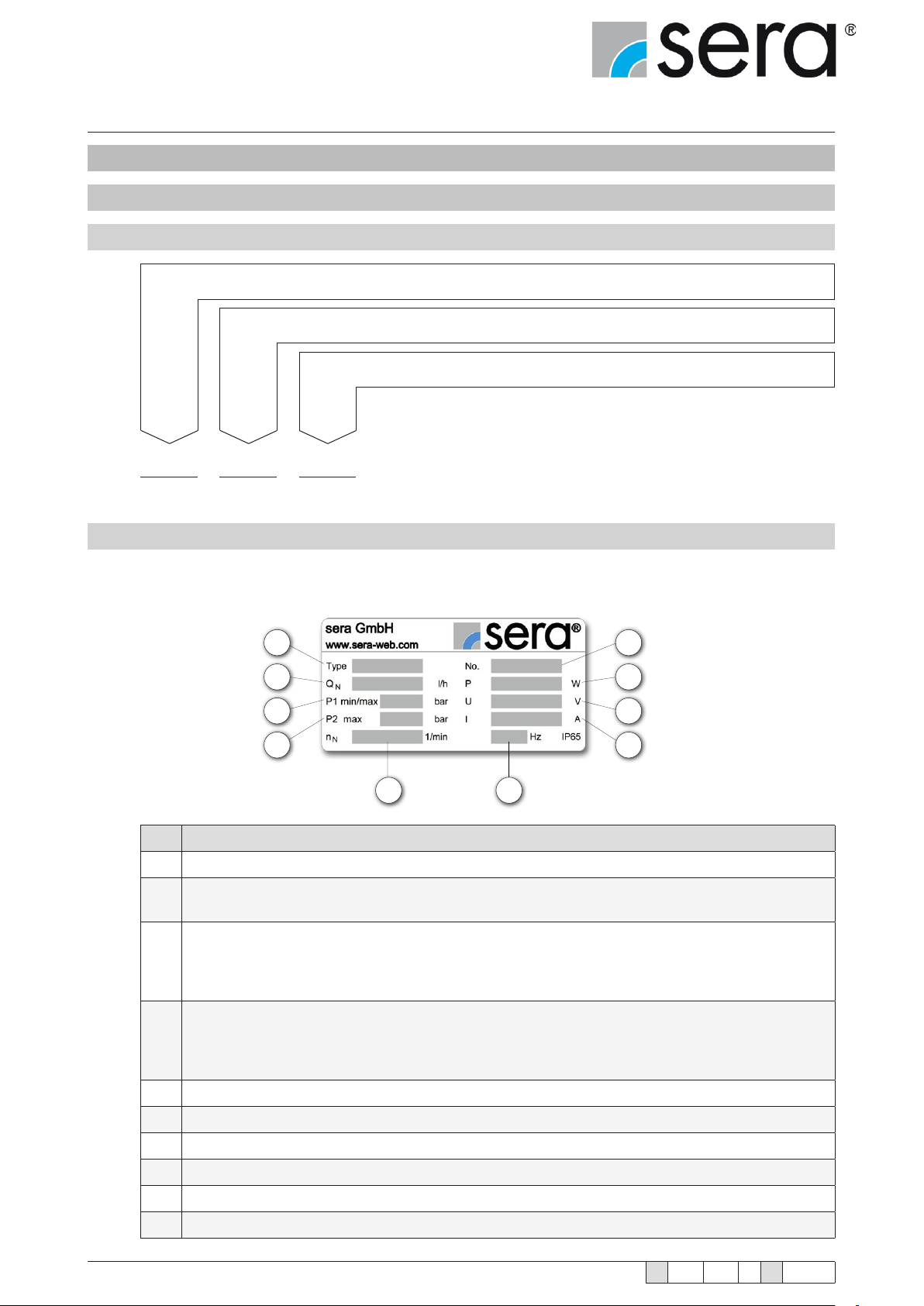
4.1 Types
4.1.1 Type key
Type of drive
Series
(litre/hour)
1 2 3
iSTEP S 20
max. nominal capacity
(example)
4.1.2 Type plate
Each sera dosing pump is factory provided with a type plate.
The following information can be found on this type plate.
1
2
3
4
5 6
7
8
9
10
12
No. Designation
1 Pump type
Nominal ow rate
2
Delivery volume of the pump at rated pressure with media similar to water.
Minimum/maximum permissible pressure in the pump inlet
Minimum/maximum permissible pressure in the inlet cross section which the pump can be used for.
3
Please consider that pressure depends on rotation speed, ow rate, temperature and static pressure
at the inlet.
Maximum permissible pressure in the pump outlet
Maximum permissible pressure in the outlet cross section which the pump can be used for. Please
4
consider that pressure depends on rotation speed, ow rate, temperature and static pressure at the
outlet.
5 Nominal stroke frequency
6 Rated frequency
7 Serial number of the pump
8 Max. power consumption
9 Max. operating voltage
10 Max. current consumption
www.sera-web.com
Subject to technical modications!
TA 508 Rev. 00 en 11/2015
Page 13

Stepper motor pump
®
iSTEP
Operating Instructions
4.2 Materials
The materials used are stated in the order conrmation and the product description.
4.3 Viscosity, pumped medium
The diaphragm pump is suitable for uids with viscosities < 100 mPas.
Medium state ► from 50 l/h, max. 5% solids, grain size 30 µm.
4.4 Noise measurement
According to DIN 45635 the measured sound pressure level of the diaphragm pumps is below 70 dB (A).
TA 508 Rev. 00 en 11/2015
Subject to technical modications!
www.sera-web.com
13
Page 14
Stepper motor pump
®
iSTEP
Operating Instructions
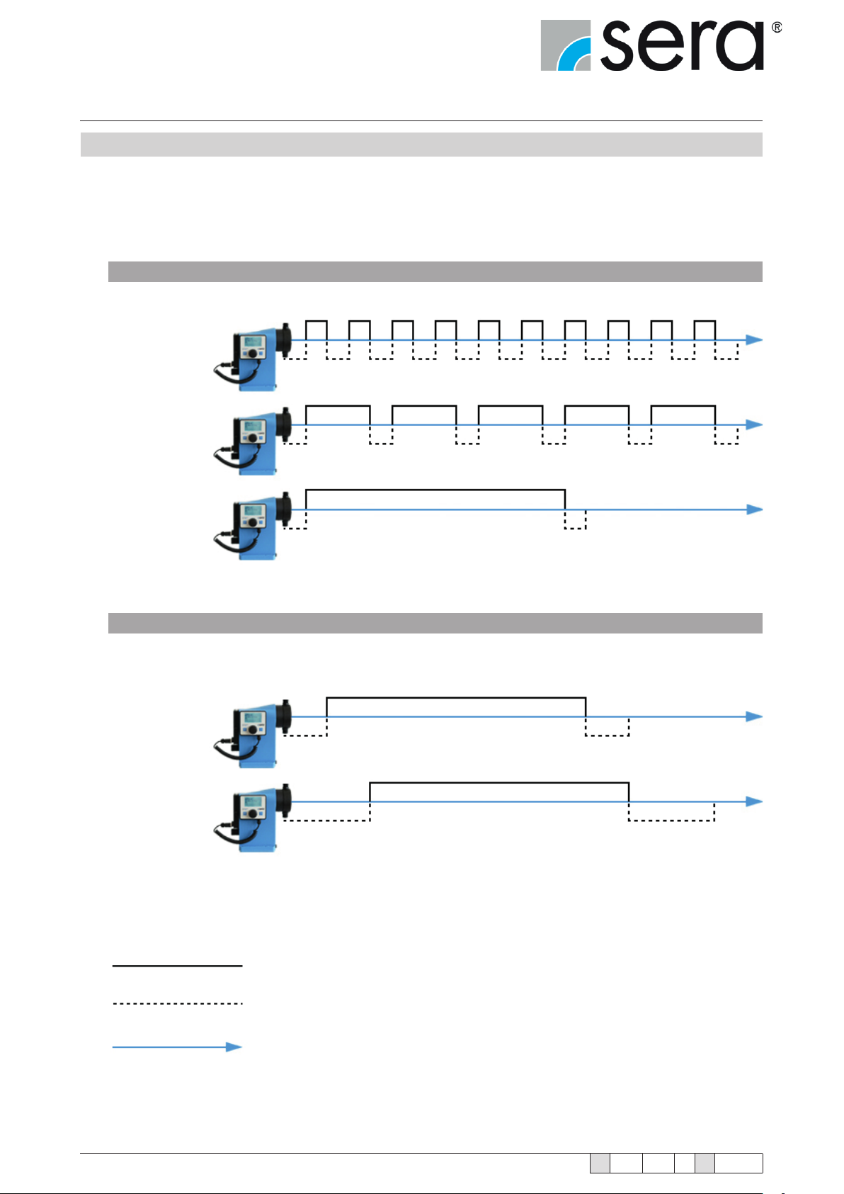
4.6 Delivery characteristic
The stepped motor pump iSTEP
For low delivery volumes, the pump runs the suction stroke at maximum speed and adjusts the speed of the pressure
stroke to the desired delivery volume. A constant ow rate is achieved that enables gentle dosing with low pulsation.
Standard Operation
100%
Flow rate
50%
Flow rate
®
can perform the pressure and suction strokes at different speeds.
10%
Flow rate
Slow Mode for viscous media
20%
Flow rate
15%
Flow rate
14
Pressure stroke
Suction stroke
Time
www.sera-web.com
Subject to technical modications!
TA 508 Rev. 00 en 11/2015
Page 15
Stepper motor pump
®
iSTEP
Operating Instructions
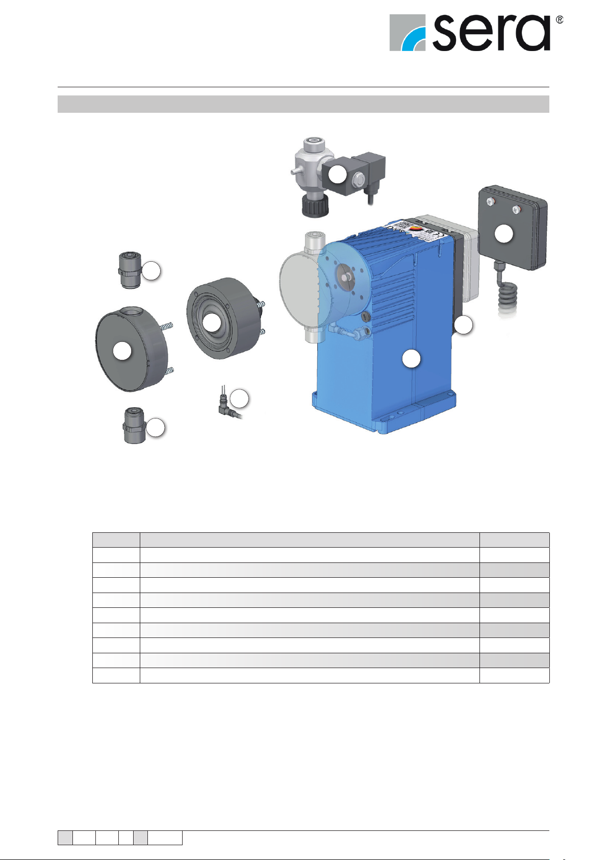
4.6 Components of the diaphragm pump
1
9
8
4
2
6
7
5
3
No. Designation Remark
1 Pressure valve
2 Pump body
3 Suction valve
4 Assembly pump
5 Diaphragm rupture monitoring device
6 Stroke mechanism
7 Electronic
8 Operating panel with graphic display
9 Automatic ventilation device
option
TA 508 Rev. 00 en 11/2015
Subject to technical modications!
www.sera-web.com
15
Page 16
Stepper motor pump
®
iSTEP
Operating Instructions
4.7 Functional description
4.7.1 General
sera dosing pumps are run-dry safe oscillating displacement pumps that are characterised by high tightness of the
dosing head. The uid is conveyed by a deformable diaphragm.
The stepper motor pumps consist of the following (main) components:
■ Drive housing
■ Assembly pump
■ Pump body
■ Suction and pressure valve
■ Electronics with control panel
■ Diaphragm rupture monitoring device
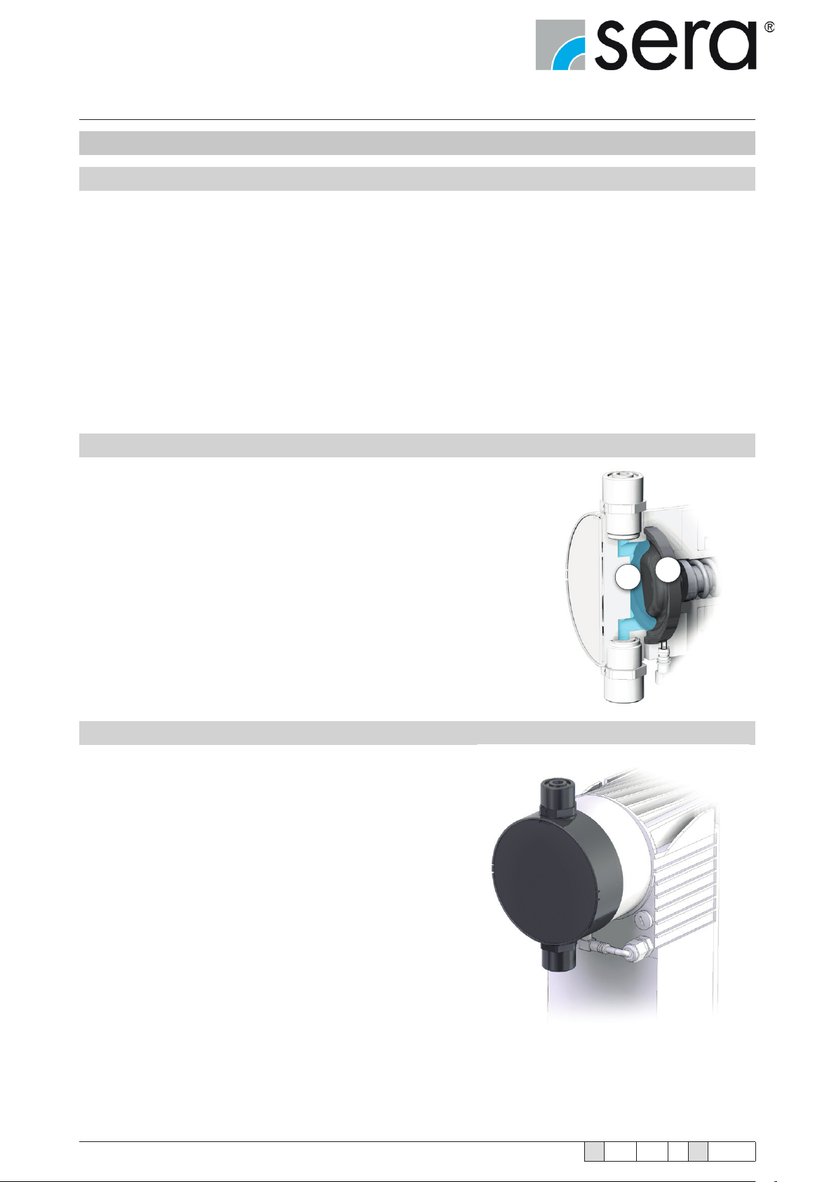
4.7.2 Stroke mechanism with assembly pump
The stroke mechanism of the sera stepped motor pump
consists of a straight slider crank mechanism that converts
the rotary movement of the stepped motor into a linear
movement.
The control of the stepped motor is performed by the
electronics integrated in the stroke mechanism.
The pumped medium (1) is conveyed by an elastic drive
diaphragm (2). The stroke movement of the drive diaphragm
is transferred to the pumped medium by the oscillating
eccentric and the push rod. This results in the suction and
pressure stroke.
4.7.3 Pump body
Depending on the applied backpressure, movements of the plastic pump body in elastic materials are possible.
This does not affect the pumps’s service life or operational reliability.
2
1
16
www.sera-web.com
Subject to technical modications!
TA 508 Rev. 00 en 11/2015
Page 17
Stepper motor pump
®
iSTEP
Operating Instructions
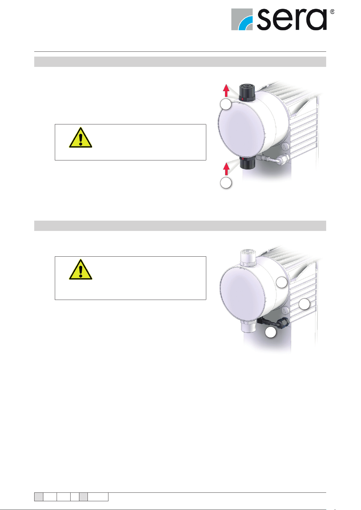
4.7.4 Suction / Pressure valve
The pump valves are ball valves that only work properly in a
vertical position. The condition of the valves has a deciding effect on the operating capability of the pump.
Valves must be exchanged as complete units.
When replacing the valves it is important to check the ow direction (1).
Pressure valve above; Suction
valve below!
ATTENTION!
4.7.5 Diaphragm rupture monitoring device
iSTEP® stepped motor pumps are equipped with a conductive
diaphragm monitoring device.
The sensitivity of the diaphragm
rupture monitoring device can
be adapted to the conductivity of
the medium via the electronics.
ATTENTION!
The diaphragm monitoring device MBE-02 (1) is mounted in the
base ring (2) and permanently connected to the electronics in
the drive housing (3).
Factory setting 50%, approx. 10
µS/cm.
1
1
2
3
TA 508 Rev. 00 en 11/2015
Subject to technical modications!
1
www.sera-web.com
17
Page 18
Stepper motor pump
®
iSTEP
Operating Instructions
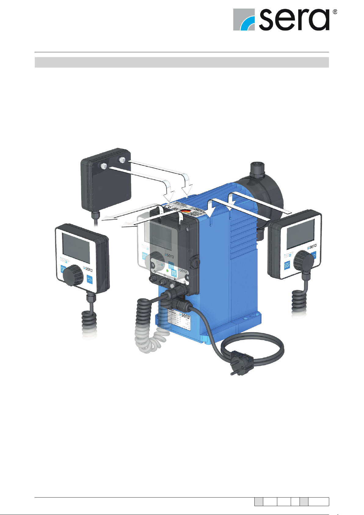
4.7.6 Electronics with removable control element
Among other things, the electronics enable the proportional dosing via analogue signals 4 … 20 mA or contact
signals with the possibility of pulse division or pulse multiplication.
The graphical display shows information about the current status of the dosing pump.
A connection for ow monitoring or ow rate measurement and an "empty" signal with pre-alarm and dry run alarm
are available as standard.
The removable control element with graphical display can be attached to the corresponding side on the housing
depending on the operating side.
18
www.sera-web.com
Subject to technical modications!
TA 508 Rev. 00 en 11/2015
Page 19
Stepper motor pump
®
iSTEP
Operating Instructions
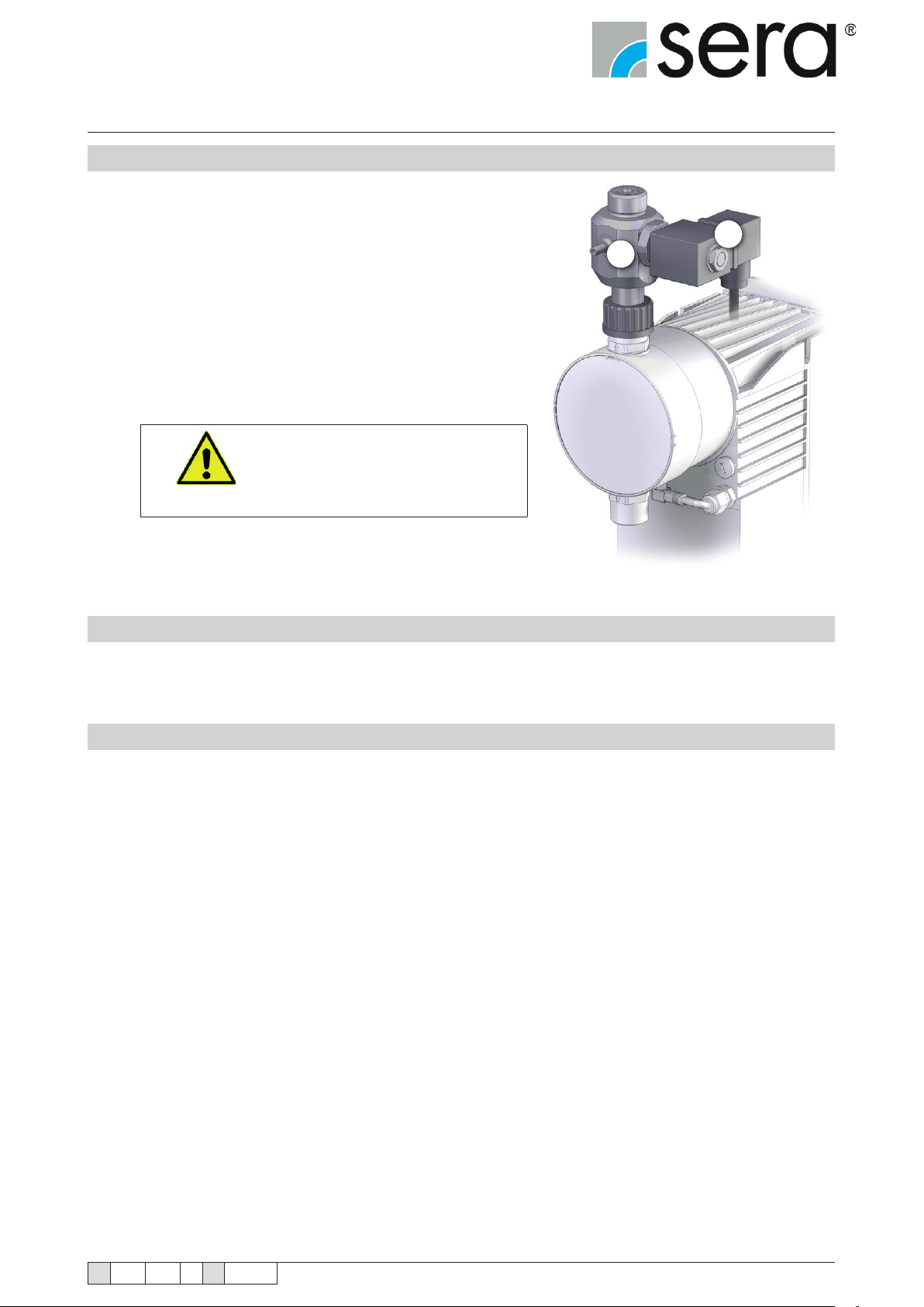
4.7.7 Automatic ventilation device (option)
An automatic ventilation device attached to the pressure port
can optionally be used for the stepped motor pumps.
The stepped motor pump vents the dosing head of the pump
and the suction line either using an external signal or manually
controlled and/or automatically at set intervals. The automatic
ventilation device consists of a combination of a check valve (1)
that should prevent the ow back of liquids and a solenoid valve
(2). When the controlled solenoid valve opens, the spring-loaded armature with attached seal is lifted from the valve seat and
pressure is relieved from the space between the pump valve
and the integrated check valve. Thus the pump and the pipe on
the suction side can be vented without pressure.
ATTENTION!
2
1
Always install the pump above
the suction container and mount
the return pipe with descending
gradient to the suction container.
4.7.8 Interface module (accessories)
The interface module provides level input and Probus or Pronet connectivity.
4.7.9 Suction lances connection (accessories)
In order to connect the stepped motor pump to a sera suction lance, an 8-pole cable connector with M12 thread
is needed (accessory part number: 90042494 or 90022885).
This cable connector is connected to the level input of the iSTEP
See chapter 7.2.3 "Level Connection" for pin assignment.
®
.
TA 508 Rev. 00 en 11/2015
Subject to technical modications!
www.sera-web.com
19
Page 20
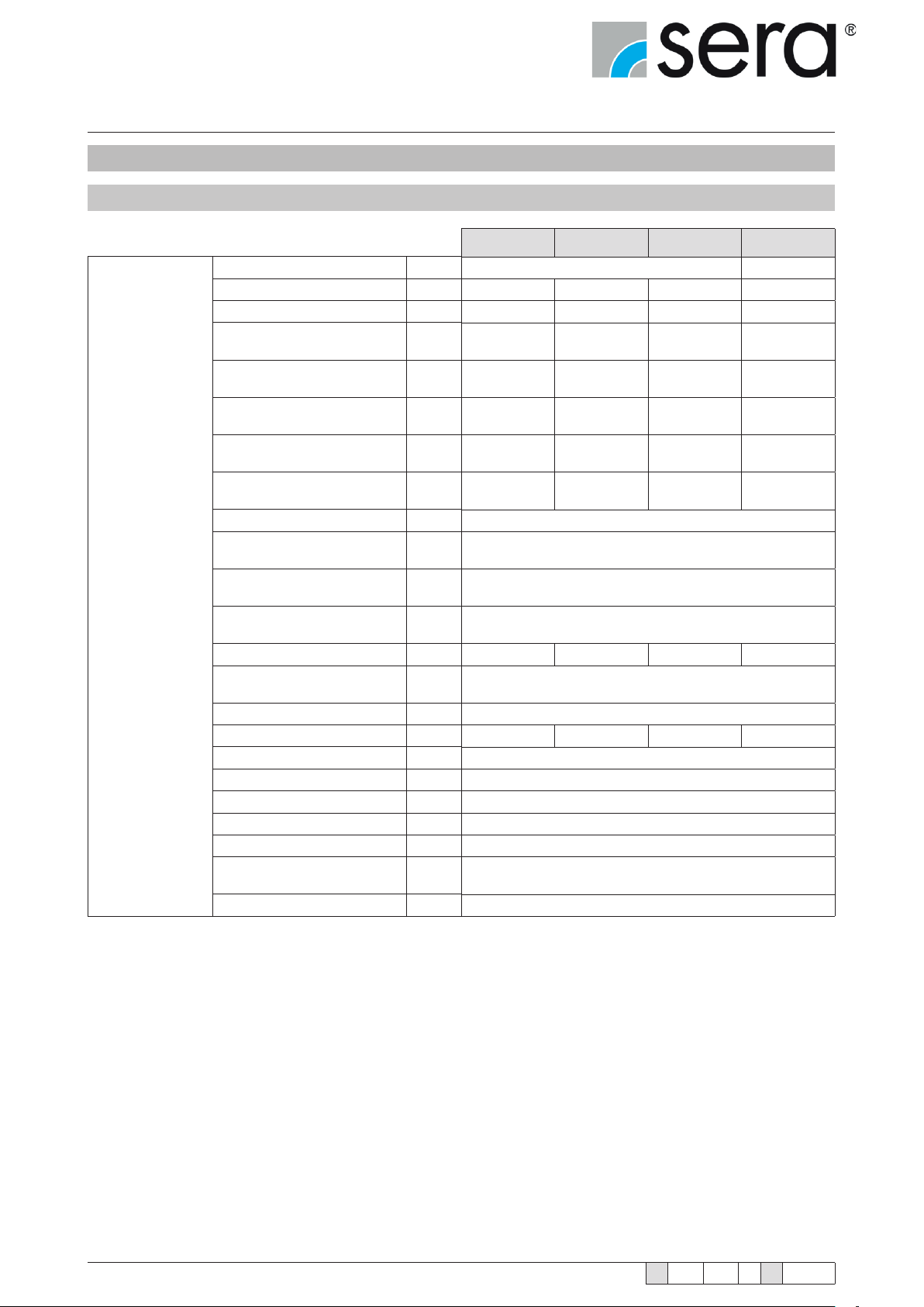
Stepper motor pump
®
iSTEP
Operating Instructions
5. Technical Data
5.1 Output data
Mechanical data
Setting range
Max. dosing capacity [l/h]
Min. dosing capacity [l/h]
Max. dosing capacity
Slow Mode 25%
Max. dosing capacity
Slow Mode 50%
Max. dosing capacity
Slow Mode 75%
Stroke volume
Max. permissible pressure
at outlet of pump (P
Accuracy of repeatability [%]
Min. permissible pressure
at inlet of pump
Max. permissible pressure
at inlet of pump
Max. suction height
(with liquids similar to water)
Nominal diameter [DN]
Max. viscosity without
spring-loaded valves
Connecting thread
Nominal frequency [1/min]
Stroke length [mm]
Max. liquid temperature [°C]
Min. liquid temperature [°C]
Max. operating temperature [°C]
Min. operating temperature [°C]
max)
2
[l/h]
[l/h]
[l/h]
[ml/
Stroke]
[bar]
[bar]
[bar]
[m WS]
[mPas]
(=cP)
®
iSTEP
S 20 iSTEP
20 30 40 50
0,02 0,03 0,04 0,05
17,3 25,8 34,3 43,4
13,5 20,1 26,6 34,0
8,3 12,0 16,0 20,6
1,75 3,33 3,51 4,39
10 7 6 3
5 5 5 8
190 150 190 190
®
S 30 iSTEP
1:1000
± 5%
-0,3
0,5
3
100
G3/4
3,5
60
10
40
0
®
S 40 iSTEP
®
S 50
20
Max. storage temperature [°C]
Min. storage temperature [°C]
www.sera-web.com
Subject to technical modications!
40
0
TA 508 Rev. 00 en 11/2015
Page 21
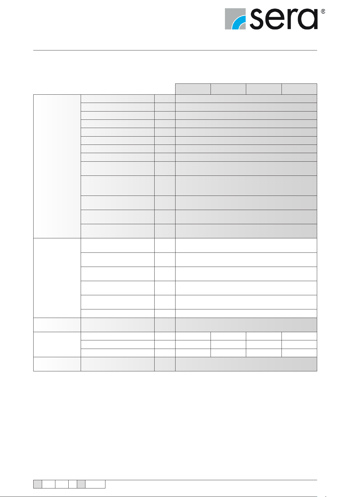
Stepper motor pump
®
iSTEP
Operating Instructions
Elektrical data
Signal input
Signal output
Weight
Dimension
Sound pressure
Max. power consumption [W]
Voltage [V]
Frequency [Hz]
Max. inrush current (100V) [A]
Max. inrush current (230V) [A]
Electrical safety class
Enclosure class
Length of mains cable [m]
Input Voltage / Control input [V DC]
Min. pulse length [ms]
Recommended fuse
230V min.
Recommended fuse
110V min.
Recommended fuse
acc. to UL489/UL1077
Max. load
Contact input
Max. load for
External stop input
Impedance at 0/4-20 mA
analog input
Max. resistance in
level input
Max. resistance in
pulse circuit
[Ω]
[Ω]
[Ω]
Sampling rate [ms]
Impedance at 0/4-20 mA
analog output
[Ω]
Plastic [kg]
Steel [kg]
Diaphragm diameter [mm]
Max. sound pressure
at max. burden
[dB(A)]
iSTEP
®
S 20 iSTEP
®
S 30 iSTEP
®
S 40 iSTEP
75
100 – 240 AC
50/60
2
1,2
II
IP65
2
24
55
C10A circuit breaker
C10A circuit breaker
C10A
24V / 10 mA
24V / 10 mA
47
4K
100K
1
120
6,1 6,1 6,1 6,3
7 7 7 7,2
44 64 64 78
LP(A)<65dB(A) +/-5dB(A)
®
S 50
TA 508 Rev. 00 en 11/2015
Subject to technical modications!
www.sera-web.com
21
Page 22
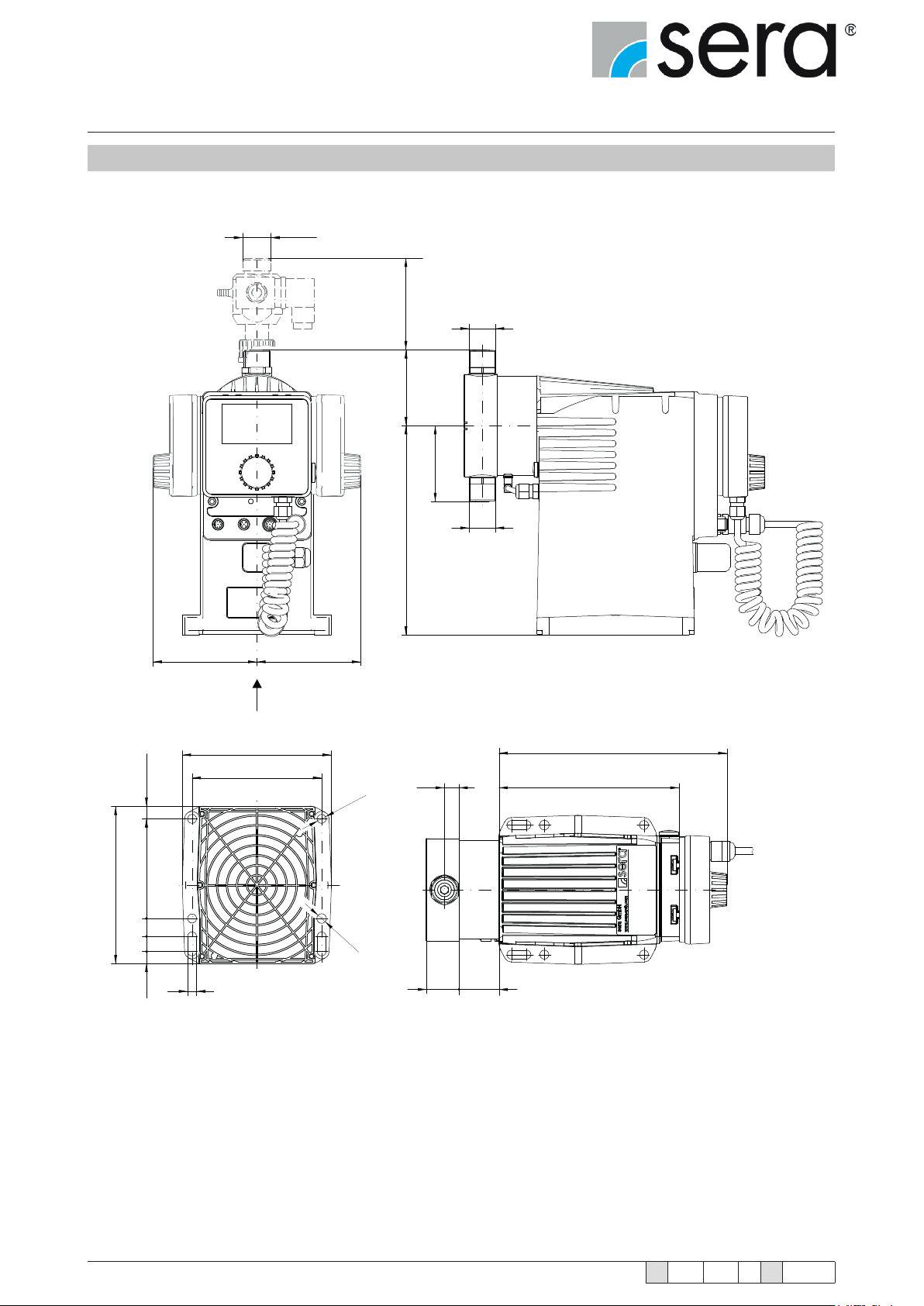
Stepper motor pump
®
iSTEP
Operating Instructions
5.3 Dimensions
G3/4
88
G
D
S
157,9
X
(12,5)
10018
15
105 105
X
149,5
130
210
G
230
B 181
Ø 9
Ø 9
22
12,4
9
www.sera-web.com
C A
Subject to technical modications!
TA 508 Rev. 00 en 11/2015
Page 23
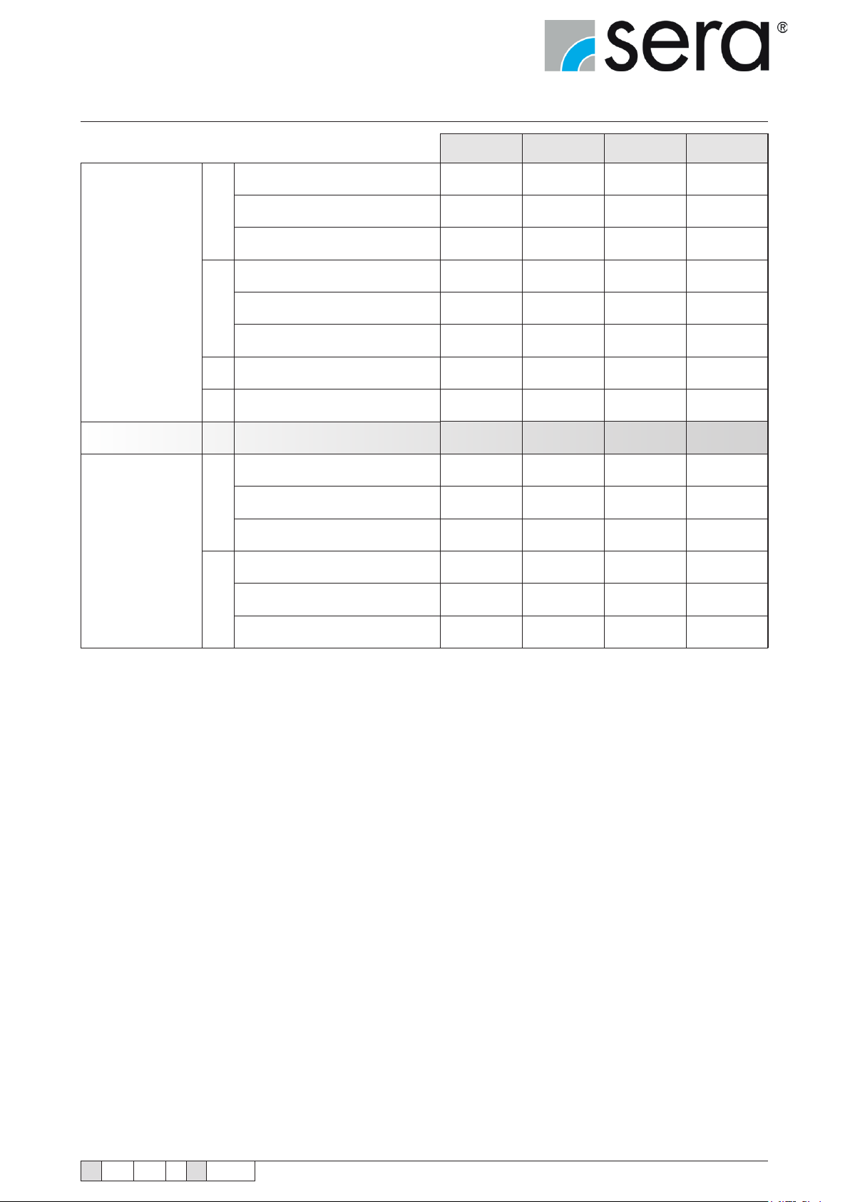
Stepper motor pump
®
iSTEP
Operating Instructions
All dimensions in mm!
Valves
Assembly pump A Assembly pump
Pump body (PB)
Double valves PVC
S
Double valves PP-FRP/ PVDF-FRP
Double valves 1.4571
Double valves PVC
D
Double valves PP-FRP/ PVDF-FRP
Double valves 1.4571
Connection thread
G
Suction/pressure valve
DN Nominal weight
Centre of valve thread
PB PVC
Centre of valve thread
B
PB PP-FRP/ PVDF-FRP
Centre of valve thread
PB 1.4571
iSTEP
®
S 20 iSTEP
®
S 30 iSTEP
®
S 40 iSTEP
65 72 72 75,1
56,6 69,6 69,6 76,1
65 72 72 75,5
65 72 72 75,1
64,6 69,6 69,6 76,1
65 72 72 75,5
G3/4 G3/4 G3/4 G3/4
5 5 5 8
37,5 40 40 40
16 14,7 14,7 14,7
17 14,7 14,7 14,7
16 14,7 14,7 14,7
®
S 50
PB PVC
C
PB PP-FRP/ PVDF-FRP
PB 1.4571
38 40,3 40,3 39,3
35 33,2 33,2 33,2
36 38,2 38,2 37,2
TA 508 Rev. 00 en 11/2015
Subject to technical modications!
www.sera-web.com
23
Page 24
Stepper motor pump
®
iSTEP
Operating Instructions
6. Assembly / Installation
■ The standard model of the pump is only approved for installation in dry areas in a non-aggressive atmosphere and
temperatures between 0 °C and +40 °C and humidity of 85% (short-term 100%), max. installation height 2000m
above sea level.
If toxic, crystallising or corrosive liquids are conveyed the pipe system must be
equipped with facilities for emptying, cleaning and if necessary rinsing with an appropriate medium.
DANGER!
Mount the dosing pump so that leaking medium cannot cause any damage.
WARNING!
■ Protect the pump from heat sources, direct sunlight and UV light.
■ See “Dimensions” chapter for dimensions of the pump connections and xing holes.
The use of washers is recommended for xing the pump. The mounting area must be at and have adequate load-
bearing capacity.
■ Fixing the pump with at least four bolts above the pump base is required for safe operation.
■ Install the pump so that there is no vibration and no tension and that it is aligned precisely.
■ Install the pump at the optimum possible operating height. Mount the pump so that the valves are vertical.
■ Ensure that there is sufcient space around the pump body and the suction and pressure valve so that these parts
can be easily dismantled if required.
■ Design the nominal diameters of the downstream piping and the valves installed in the system to be the same size
or larger than the nominal inlet and outlet diameters of the pump.
■ To check the pressure ratios in the piping system, it is recommended to provide connections for pressure measure-
ment ttings (e.g. manometers) near the suction and pressure ports.
■ Drain valves must be provided.
■ Before connecting the pipes, remove the plastic caps on the suction and pressure ports of the pump.
■ Check the fastening bolts for the pump body for tightness and tighten if necessary, see “Overview of the tightening
torques” chapter.
■ Connect pipes to the pump so that there are no forces acting on the pump, such as e.g. misalignment, weight or
strain of the pipe.
■ Keep the suction pipes as short as possible.
■ Use pressure and medium resistant hoses / pipes.
■ All pipes and containers connected to the pump must comply with the regulations and must be cleaned, tension-free
and intact.
WARNING!
24
The pump must be adequately fastened at the installation site.
www.sera-web.com
Subject to technical modications!
TA 508 Rev. 00 en 11/2015
Page 25
Stepper motor pump
®
iSTEP
Operating Instructions
In order to avoid cavitation, overload or excessive delivery, the following points should be noted:
■ Avoid high suction heights.
■ Keep pipes as short as possible.
■ Select sufciently large nominal diameters.
■ Avoid unnecessary choke points.
■ Install a pulsation damper.
■ Install overpressure protection.
■ Install a pressure-sustaining valve, if necessary
■ Provide feed line for outgassing media.
Bei Zulauf sind vom Betreiber geeignete Schutzmaßnahmen (z.B. Auffangwanne) zu
ergreifen, damit im Falle eines Membranbruches ein Leerlaufen des Behälters vermieden wird.
WARNING!
WARNING!
DANGER!
Install the return line of overpressure protection and/or ventilation valve sloping
downward into the associated tank.
The pump is only designed for operation outside Ex-zones!
TA 508 Rev. 00 en 11/2015
Subject to technical modications!
www.sera-web.com
25
Page 26
Stepper motor pump
®
iSTEP
Operating Instructions
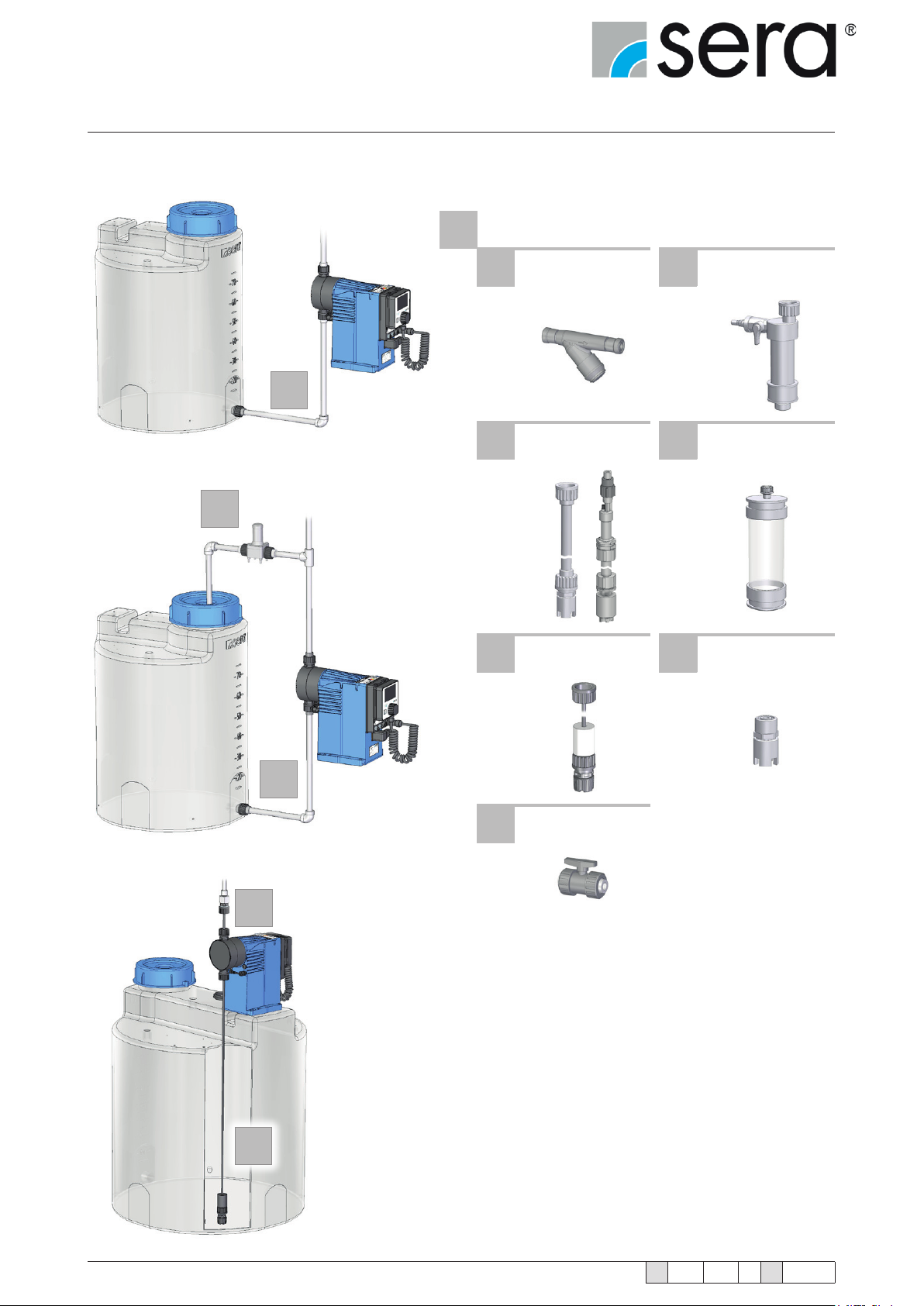
The following fittings can be used on the
suction side:
1 SUCTION SIDE
2.7
1.1 Line strainer 1.2
Suction aid
Siphon vessel
1
1.3 Suction lance 1.4 Multifunction device
1.5 Dosing set 1.6 Foot valve
2.10
1.5
1
1.7 Shut-off valve
26
www.sera-web.com
Subject to technical modications!
TA 508 Rev. 00 en 11/2015
Page 27
Stepper motor pump
®
iSTEP
Operating Instructions
2
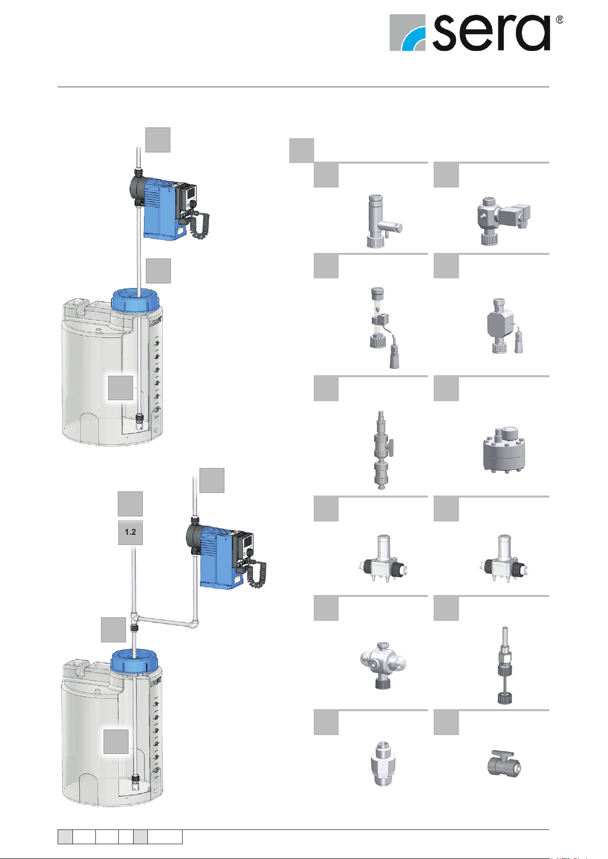
The following fittings can be used on the
pressure side:
1 PRESSURE SIDE
1.3
2.1 Vent valve 2.2
1
2.3 Flow monitor 2.4 Flow meter
2.5 Injection tting 2.6 Pulsation damper
Automatic ventilation
device (option)
1
1.3
1.4
1.2
2
2.7 Diaphragm relief valve 2.8
2.9 Multifunction valve 2.10 Dosing set
2.11 Dosing valve 2.12 Shut-off valve
Diaphragm pressurekeeping valve
TA 508 Rev. 00 en 11/2015
Subject to technical modications!
www.sera-web.com
27
Page 28
Stepper motor pump
®
iSTEP
Operating Instructions
1.1
Line Strainer
Connect suction line slightly above the bottom of the tank and install a line strainer (0.1 – 0.5 mm mesh size – depending on valve nominal diameter of the pump).
If impurities are not removed, this results in malfunctions of
the pump and the system.
ATTENTION!
1.2
Suction aid / siphon vessel
For high tanks without connection on the bottom of the tank ► install suction aid / siphon vessel.
Thereby, pay attention to accelerating pressures which may be generated in a long suction pipe.
1.3
Suction lance
Install a suction lance for removal of chemicals from tanks and barrels.
The integrated foot valve prevents the backow of the suctioned medium.
The suction lances are equipped with a level switch for "empty" signal.
1.4
Multifunction device
The multifunction device is installed in the suction side piping of the dosing pump and is used for determination of the
delivery rate of dosing pumps under real operating conditions.
The device can be lled either using a pending tank volume (communicating container) or using a hand vacuum pump.
1.5
Dosing set
The dosing set consists of dosing hose, threaded hose coupling and dosing valve (pressure side) and foot valve
(suction side).
1.6
Foot valve
To prevent running dry of the suction line ► install foot valve (check valve) at the end of the suction line.
2.1
Vent valve
If air can be drawn in due to falling liquid level in the suction tank and at the same time delivered to a pressurised line
or against a pressure-sustaining valve ► install vent valve in the pressure line.
28
www.sera-web.com
Subject to technical modications!
TA 508 Rev. 00 en 11/2015
Page 29
Stepper motor pump
®
iSTEP
Operating Instructions
The delivery ow can be interrupted if there is air in the suction line!
NOTE!
2.2
Automatic ventilation device (option)
If outgassing media are delivered in a pressurised pipe or against a pressure-sustaining valve ► install automatic
ventilation device in the pressure line.
The delivery ow may be interrupted if air/gas remains in the suction pipe!
ATTENTION!
In the case of media which tend to crystallising when they come in contact with
air, the return line of the automatic ventilation device must be laid in a loop in order to prevent contact of the medium with air in the outlet area of the vent valve.
NOTE!
2.3
Flow monitor
To record the ow rate of the pump ► install ow monitor.
The application range is restricted to media that are similar to water.
The ow monitor is screwed upright on the pressure port of the dosing pump and connected to the pump electronics
via the input for ow monitoring.
2.4
Flow meter
For measurement and monitoring of the ow rate ► install ow meter.
The application range is restricted to media that are similar to water.
The ow meter is screwed upright on the pressure port of the dosing pump and connected to the pump electronics
via the input for ow monitoring.
2.5
Injection tting
Install an injection tting that routes into a main line to prevent the backow of the pumped medium in the dosing line.
Unwanted mixing in the dosing line occurs if any possible backow from the main
line is not prevented.
DANGER!
TA 508 Rev. 00 en 11/2015
Subject to technical modications!
www.sera-web.com
29
Page 30
Stepper motor pump
®
iSTEP
Operating Instructions
2.6
Pulsation damper
Damping of the pulsation by installation of pulsation dampers if:
■ a low-pulsation delivery ow is desired for process reasons,
■ acceleration forces caused by the piping geometry must be removed.
Install pulsation damper as close as possible to the pump head.
If both pulsation damper and pressure-sustaining valve should be integrated, install the pressure-sustaining valve
between pump and pulsation damper.
Undamped acceleration forces can result in the following faults / damage:
■ ow rate uctuations
WARNING!
■ dosing errors
■ pressure surges
■ valve shocks
■ increased wear on the suction and pressure sides of the pump
■ mechanical destruction of the pump
■ leaks and valve shocks if the permissible maximum pressure on the pump pres-
sure side is exceeded
■ damage to the piping and its installed ttings
2.7
Diaphragm relief valve
If the permissible pressure in the system can be exceeded by closing any shut-off valve or by clogging of the line ►
install diaphragm relief valve.
When using an external overow valve, the following is applicable for the return line:
■ Route the return line sloping downward into the storage tank which is under atmospheric pressure or into an
open drainage channel.
■ Or connect directly to the pump suction line, but only if there is no check valve in the suction line (e.g. foot valve
of a suction lance).
Shut-off valves must not be closed when the pump is running!
ATTENTION!
An overpressure protection device (e.g. relief valve) must generally be provided if
the permissible operating pressure can be exceeded.
CAUTION!
ATTENTION!
30
If the permissible operating pressure is exceeded and the pump is not equipped
with overpressure protection, the pump will be damaged.
www.sera-web.com
Subject to technical modications!
TA 508 Rev. 00 en 11/2015
Page 31
Stepper motor pump
®
iSTEP
Operating Instructions
The pumped medium can spray out if the pump is damaged.
DANGER!
2.8
Diaphragm pressure-keeping valve
If dosing into a main line with negative pressure ►install pressure-keeping valve in the dosing line.
It must be ensured during the installation that excess delivery (due to positive
pressure difference (≥ > 1 bar) between pressure and suction sides) is avoided.
ATTENTION!
2.9
Multifunction valve
The multifunction valve provides the following functions:
■ pressure-keeping valve function,
■ overow valve function,
■ pressure relief function,
■ venting.
The multifunction valve is mounted directly on the pump pressure port.
2.10
Dosing set
The dosing set consists of dosing hose, threaded hose coupling and dosing valve (pressure side) and
foot valve (suction side).
2.11
Dosing valve
Installation of the dosing valve prevents the liquid from the system to be treated being able to penetrate into
the dosing line.
TA 508 Rev. 00 en 11/2015
Subject to technical modications!
www.sera-web.com
31
Page 32
Stepper motor pump
®
iSTEP
Operating Instructions
7. Electrical connections
7.1 Mains power connection
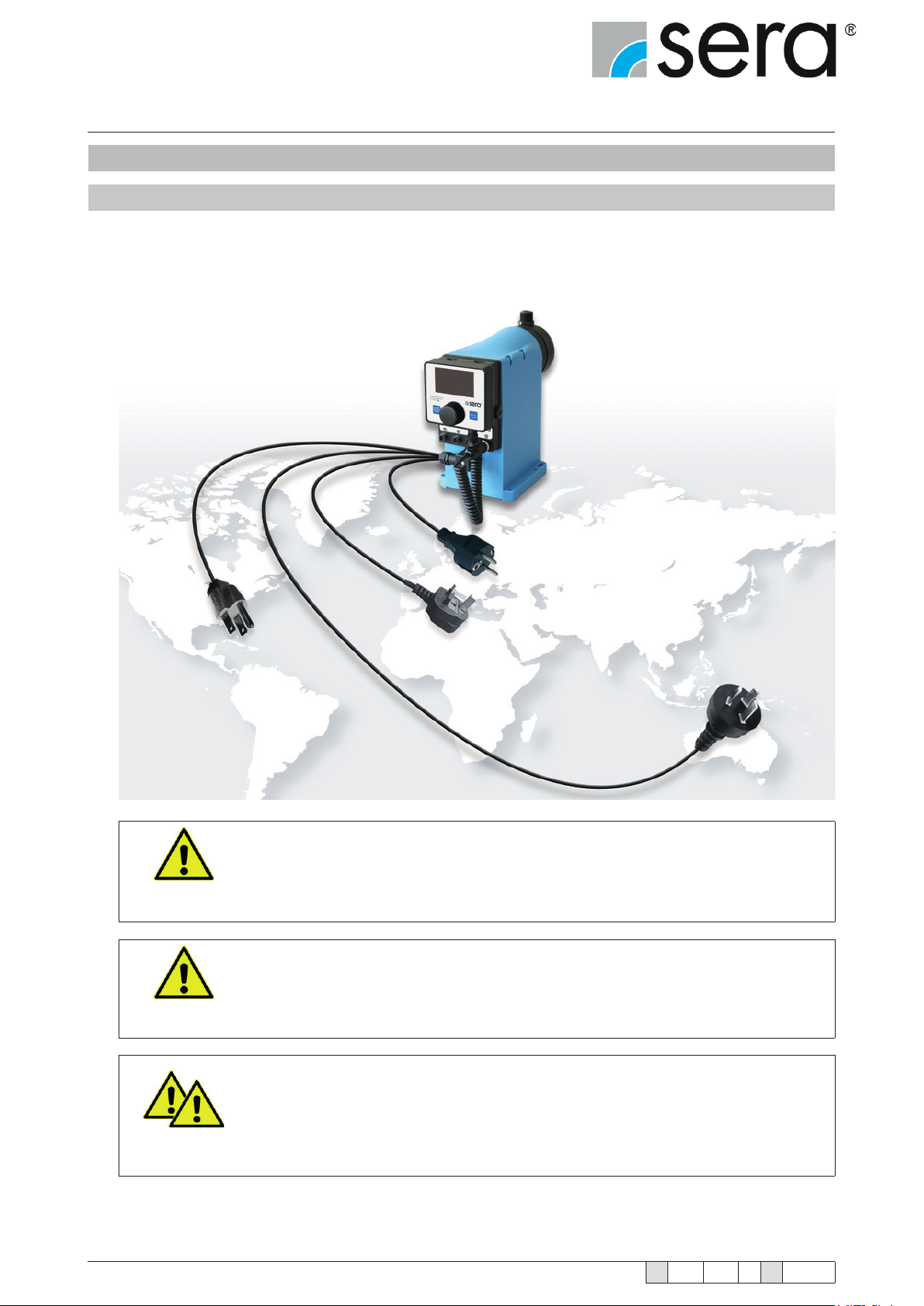
The sera stepped motor pump is supplied ready for connection with a 2m long power cable, SCHUKO plug
in the standard version and optionally with the customer-specic mains power connection.
The variable mains power connection enables worldwide use of the stepped motor pump.
The standard version is designed for an operating voltage range of 100 – 240 V, 50/60 Hz.
ATTENTION!
ATTENTION!
DANGER!
32
The pump restarts in the selected operating mode with the specied parameters
after switching on again or after restoration of the power supply following a power
failure.
Switching the voltage supply on and off temporarily must be avoided!
Only operate the pump when it is connected to a fused and earthed mains power
supply!
Do not operate pump without connected earth conductor.
www.sera-web.com
Subject to technical modications!
TA 508 Rev. 00 en 11/2015
Page 33
Stepper motor pump
®
iSTEP
Operating Instructions
7.2 Electrical interfaces
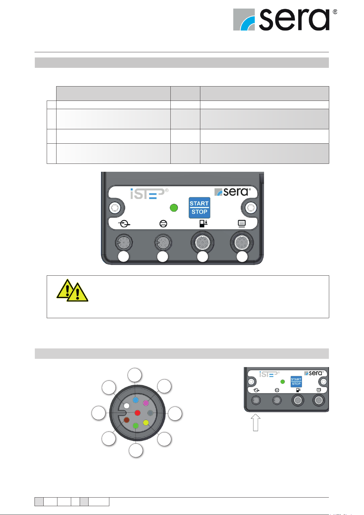
The stepped motor pump has 4 interfaces:
Interface Assign-
1 External control 8-pole Control inputs / control outputs
2 Flow monitoring and ow rate measurement 5-pole
Level connection
3
Interface module
Manual control
4
USB port
1
ment
8-pole
8-pole
2 3 4
Function
Monitoring of the dosing ow.
Set-up of a control circuit with a
connected ow meter
Pre-alarm and dry running protection.
Connection for interface module.
Adjustment / operation of the stepped motor pump.
For rmware updates and for the data transfer between
pumps (see chapter 10.10.7 "Data transfer").
Seal unused control ports with protective caps.
DANGER!
7.2.1 External control
WN
RD
BN
BU
PK
GY
YE
GN
TA 508 Rev. 00 en 11/2015
Subject to technical modications!
www.sera-web.com
33
Page 34

Stepper motor pump
®
iSTEP
Operating Instructions
All inputs and outputs can be freely parametrised.
Pin assignments Function
(factory setting)
WH (white) Input 1 Impulse Recipe
BN (brown) Input 2 External stop Recipe
GN (green) Input 3 OFF Multiple pulse
GY (grey) Output 1 Collective fault Stroke signal
PK (pink) Output 2 Stroke signal Pre-alarm level
BU (blue) Analogue output Analogue input Flow meter
YE (yellow) 24 V external 24 V external ---
RD (red) Ground Ground ---
Other functions
External stop
Batch Start
Analogue 1/2
Venting
OFF
Impulse
Batch Start
Analogue 01
Batch Volume
Batch Speed
Venting
OFF
External stop
Batch Start
Analogue 02
Batch Volume
Batch Speed
Venting
Impulse
Pre-alarm level
Dry-Running
Diaphragm rupture
Batch nished
Internal error
No ow
Collective signal
Pump active
OFF
Ready to Run
Dry-Running
Diaphragm rupture
Batch nished
Internal error
No ow
Collective signal
Pump active
OFF
Ready to Run
Collective fault
Remaining batch
Stroke frequency
34
www.sera-web.com
Subject to technical modications!
TA 508 Rev. 00 en 11/2015
Page 35
Stepper motor pump
®
iSTEP
Operating Instructions
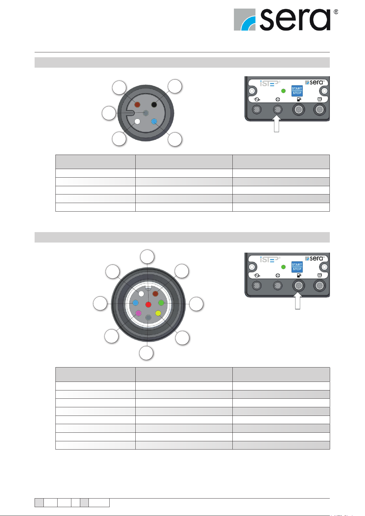
7.2.2 Flow monitoring and ow rate measurement
BN
BK
GY
WH
Wire colour Pin Function
BN (brown) Pin 1 Analogue input (0/4-20 mA)
WH (white) Pin 2 Inductive sensor (NAMUR)
BU (blue) Pin 3 Digital input
BK (black) Pin 4 15 V output (20 mA max.)
GY (grey) Pin 5 Ground
BU
(factory setting)
7.2.3 Level Connection
RD
WN
BU
PK
BN
GN
YE
GY
Wire colour Pin Function
WH (white) Pin 1 24 V (10 mA max.)
BN (brown) Pin 2 Special function
GN (green) Pin 3 Special function
YE (yellow) Pin 4 Not assigned
GY (grey) Pin 5 Special function
PK (pink) Pin 6 Pre-alarm level
BU (blue) Pin 7 Dry-Running
RD (red) Pin 8 Ground
(factory setting)
The inputs can be switched using a oating contact signal.
Pre-alarm and dry running are set to normally open oating contacts at the factory.
The sockets of the connections are A-coded and the assignations of the functions are symbolically labelled.
TA 508 Rev. 00 en 11/2015
Subject to technical modications!
www.sera-web.com
35
Page 36
Stepper motor pump
®
iSTEP
Operating Instructions
8. Operation in Ex-zone
The dosing pump is only designed for operation outside Ex-zones!
DANGER!
9. Start-up
Adequate fastening at the pump foot and compliance with the operating parameters specied in the technical data are
required for the operation of the pump.
Checks before every start-up:
■ Check all connections for tightness.
■ Tighten xing bolts of the pump body with the specied tightening torques
(see "Overview of the tightening torques" chapter).
■ Check of the electrical connections.
■ Check of the mains voltage on the rating plate with the local conditions.
Completely remove remaining liquid residues from the pump test (water). Unwanted
reactions between test and pumped medium can occur in the case of non-observance!
DANGER!
Connect hydraulic connection lines free of tension and seal tightly before suctioning
pumped medium.
DANGER!
Check parametrisation of the pump and control signals.
Unforeseen start-up of the pump can occur.
DANGER!
DANGER!
36
Before connecting the power, ensure that all seals and the hydraulic connection lines
are correctly installed and that unused connections are sealed with protective caps.
www.sera-web.com
Subject to technical modications!
TA 508 Rev. 00 en 11/2015
Page 37
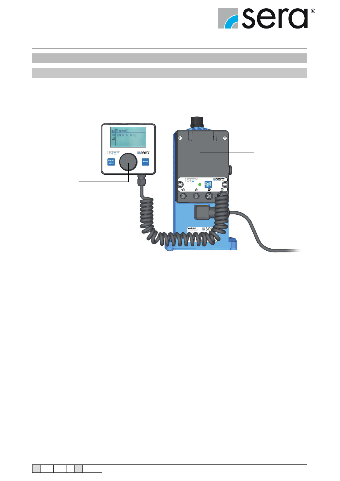
Stepper motor pump
®
iSTEP
Operating Instructions
10. Operation
10.1 Controls
Manual control
with graphical display
iSTEP case
"BACK"
Graphical
display
LED (status)
"START/STOP" "START/STOP"
Click wheel
TA 508 Rev. 00 en 11/2015
Subject to technical modications!
www.sera-web.com
37
Page 38
Stepper motor pump
®
iSTEP
Operating Instructions
10.2 Navigation
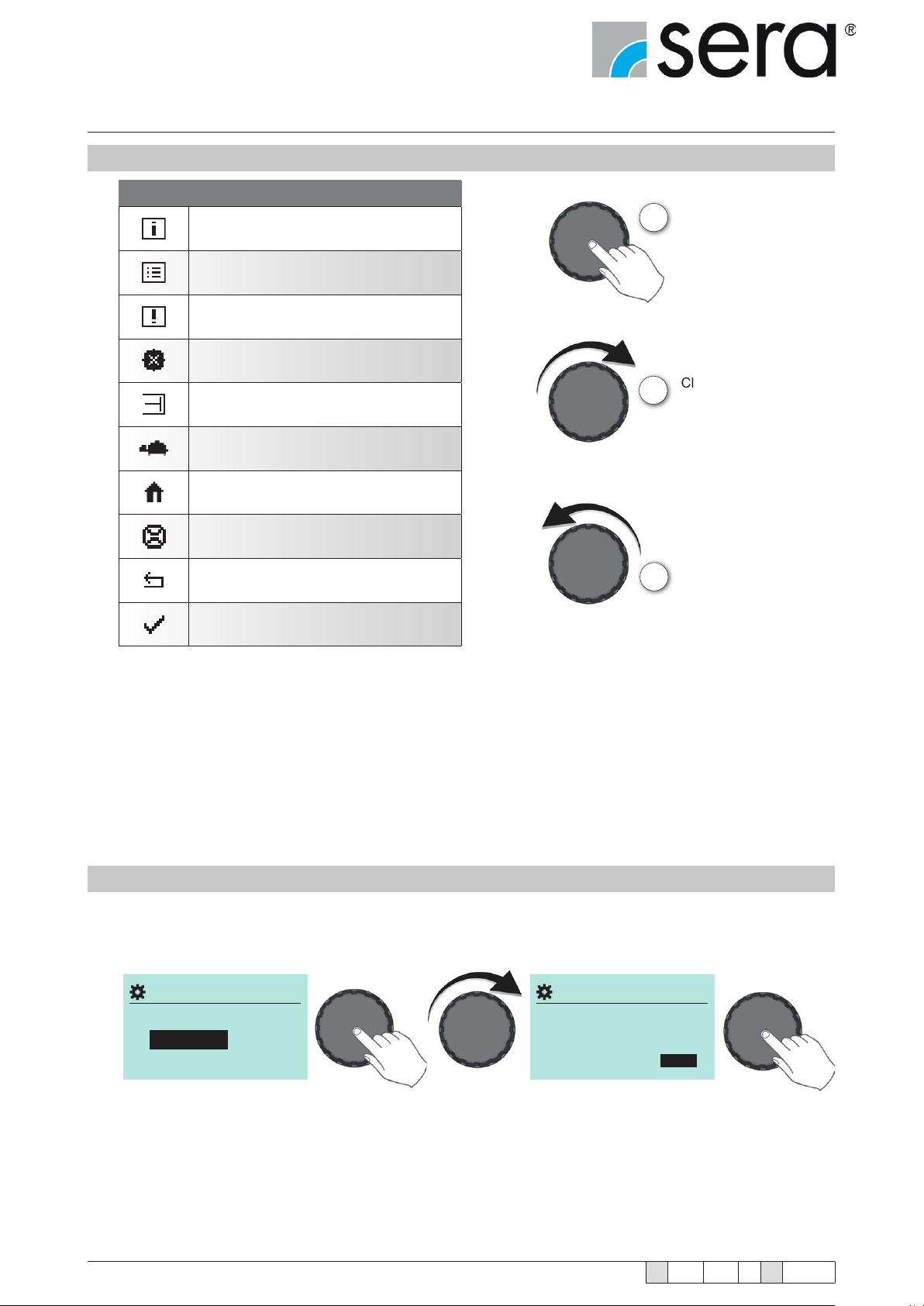
DISPLAY SYMBOLS
Information
Adjustment
Warning message
External stop
Stroke movement
SLOW MODE
1
Tap the Click-Wheel
Click-Wheel rotation right
2
Home
Flow measurement
Back
Selected
The Information, Settings and Warnings main menus have submenus and options.
Tapping the Back button always reaches the higher level menu.
A menu is selected by rotating the click wheel (2) (3) and tapping (1) opens the next menu level.
The position of the cursor always has a black background.
To change a numeric value, tap the click wheel (1) and select the value by rotating it.
Turning the click wheel to the right (clockwise) (2) increases the value and to the left (anticlockwise) (3)
reduces the value. Tapping (1) conrms the desired value and the cursor is free again.
Click-Wheel rotation left
3
10.3 Start-up (initial commissioning)
sera Settings
Select your language
DEUTSCH
weiter
■ Set the date and time in the same way as the language setting.
■ Start-up completed.
Default settings ► see parameters list (see chapter 10.7)
38
www.sera-web.com
sera Settings
Select your language
DEUTSCH
Subject to technical modications!
weiter
TA 508 Rev. 00 en 11/2015
Page 39
Stepper motor pump
®
iSTEP
Operating Instructions
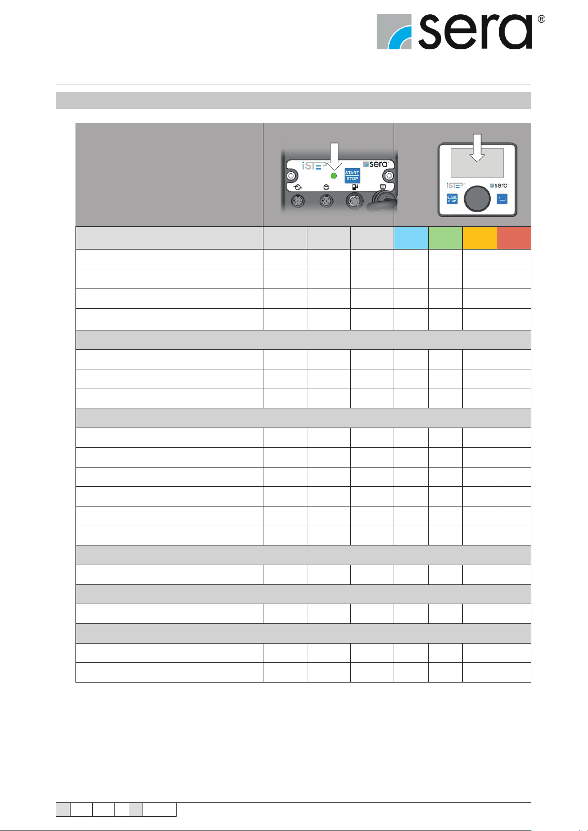
10.4 LED-Betriebsanzeigen
Operation indicators
LED (electronics case) Display
overview
LED
(green)
Ready x x
Pump active ashing x
Internal error x x
Mains voltage too low / too high x x
Level monitoring:
Level pre-alarm – pump in operation ashing ashing ashing
Level pre-alarm – pump stopped x x
Dry running x x
LED (yel-
low)
LED
(red)
blue green orange red
Dosing monitoring (ow monitor or ow meter)
No ow – warning – pump in operation ashing ashing ashing
No ow – warning – pump stopped x x
No ow – shutdown x x
Flow rate too low – Warning message ashing ashing ashing
Flow rate too low – Warning message x x
Flow rate too low – Shutdown x x
Optional diaphragm rupture monitoring
Diaphragm rupture x x
Vent valve
Venting x x
Analogue operation
mA signal < 3.5 mA x x
mA signal > 20.5 mA x x
TA 508 Rev. 00 en 11/2015
Subject to technical modications!
www.sera-web.com
39
Page 40
Stepper motor pump
MANUELL
ANALOG
MANUELLMANUAL
IMPULSE
ANALOGANALOG
BATCH
TIMER
®
iSTEP
Operating Instructions
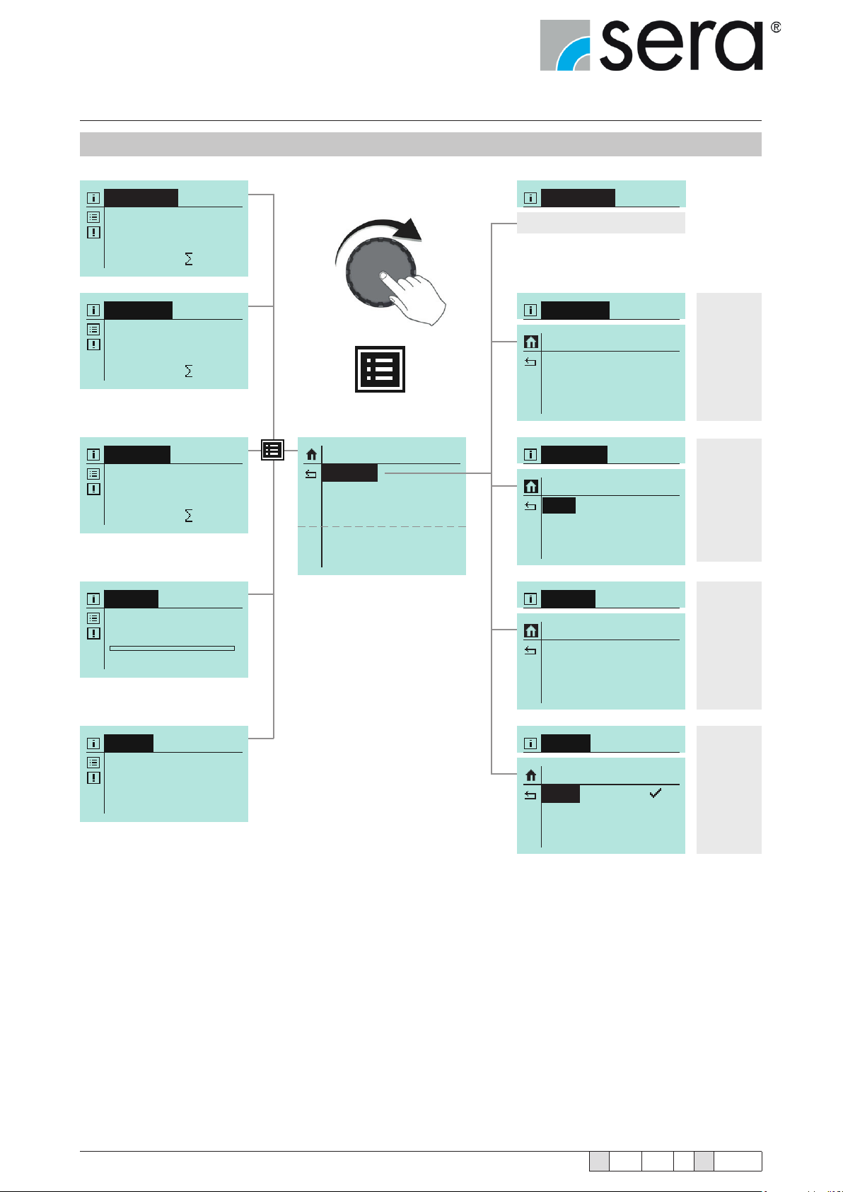
10.5 Menü
MANUAL
100.0 % freq.
0 N
IMPULSE
100.0 % freq.
Factor: 1/1
0 NMemory: 0
no parameters
PARAMETER
Memory
Mode
Factor
ON
1/1
1/1
see
chapter
10.6.2
ANALOG
100.0 % freq.
Signal: 0-20mA
0 NE1: 0.00 mA
BATCH
Batch 1 Manual
V: 0N
0.0 % freq. Start
TIMER
No Timer chosen!
SETTINGS
Parameter
In-/Outputs
Extras
System
Calibration
PARAMETER
Signal
4-20mA
PARAMETER
Batch 1
Batch 2
Batch 3
PARAMETER
Timer 1
Timer ....
Timer 10
see
chapter
10.6.3
see
chapter
10.6.4
see
chapter
10.6.5
40
www.sera-web.com
Subject to technical modications!
TA 508 Rev. 00 en 11/2015
Page 41
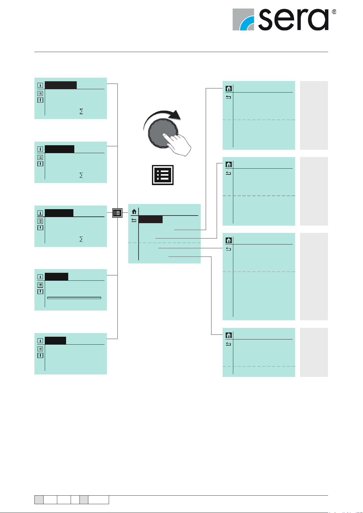
Stepper motor pump
MANUELL
ANALOG
®
iSTEP
Operating Instructions
MANUAL
100.0 % freq.
0 N
IMPULSE
100.0 % freq.
Factor: 1/1
0 NMemory: 0
ANALOG
100.0 % freq.
Signal: 0-20mA
0 NE1: 0.00 mA
BATCH
Batch 1 Manual
V: 0N
0.0 % freq. Start
SETTINGS
Parameter
In-/Outputs
Extras
System
Calibration
IN/OUTPUTS
Input 1
Input 2
Input 3
Output 1
Output 2
Analog Output
EXTRAS
Slow-Mode
Speed Limit
Dosing Monitor
Diaph. Monitor
Level
De-Aeration
SYSTEM
Language
Display
SD-Card
Time
Password
Maintenance
Data Transfer
Factory Reset
see
chapter
10.8
see
chapter
10.9
see
chapter
10.10
TIMER
No Timer chosen!
TA 508 Rev. 00 en 11/2015
Subject to technical modications!
CALIBRATION
Active
Strokes
Frequency
Start Calibration
www.sera-web.com
No
0200
080%
see
chapter
10.11
41
Page 42
Stepper motor pump
Manuell
ANALOG
®
iSTEP
Operating Instructions
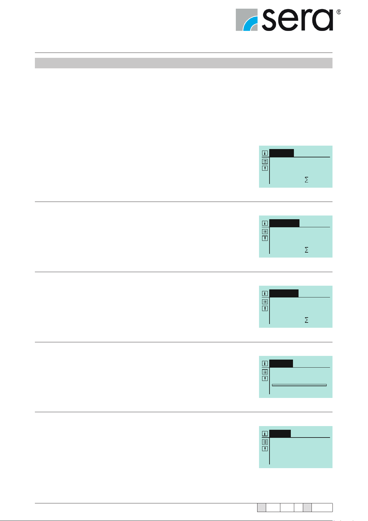
10.6 Operating modes
You can select between ve different operating modes:
■ MANUAL
■ IMPULSE
■ ANALOGUE
■ BATCH
■ TIMER
MANUAL
Local operation and control of the pump without external control. The ow rate
can be set by specifying a stroke frequency. With a calibrated pump, the ow rate
is set in l/h instead of via the stroke frequency.
Manual
100.0 % freq.
SEE CHAPTER 10.6.1
IMPULSE
The pump can be operated using incoming pulses with transmission, reduction,
1/1 or with contact water meter (adjustment of the speed).
SEE CHAPTER 10.6.2
ANALOG
The stroke frequency of the pump is controlled via the received analogue signal.
SEE CHAPTER 10.6.3
BATCH
Batch dosing that is optionally manual using an external pulse signal from an incoming analogue signal. The batch quantity can be entered in strokes or in litres
(only with a calibrated pump).
SEE CHAPTER 10.6.4
0 N
IMPULSE
100.0 % freq.
Factor: 1/1
0 NMemory: 0
ANALOG
100.0 % freq.
Signal: 0-20mA
0 NE1: 0.00 mA
BATCH
Batch 1 Manual
V: 0N
0.0 % freq. Start
TIMER
It is possible to select between ten different timer settings.
SEE CHAPTER 10.6.5
42
www.sera-web.com
Subject to technical modications!
TIMER
No Timer chosen!
TA 508 Rev. 00 en 11/2015
Page 43
Stepper motor pump
®
iSTEP
Operating Instructions
10.6.1 MANUAL operating mode
Standard adjustment of the delivery volume is made using the stroke frequency (0-100% in 0.1% steps).
After any calibration, the delivery volume is entered in the display as setpoint in l/h instead of by stroke frequency
adjustment (see chapter 10.11 "Calibration"). In the “Operating messages” view, the stroke frequency display is
replaced accordingly with the ow rate display. The total delivery volume is also still indicated in litres.
NOTE!
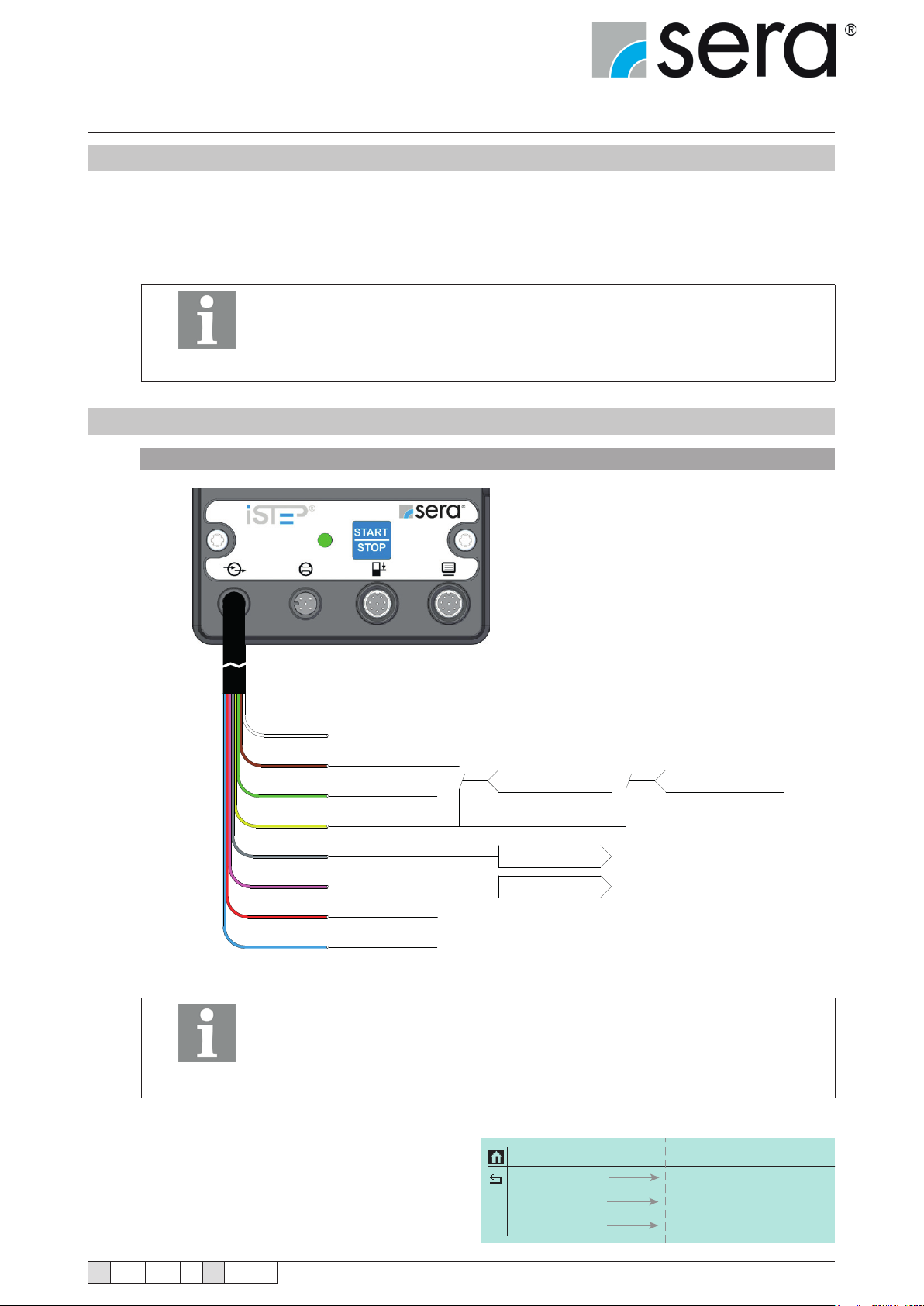
10.6.2 IMPULSE operating mode
Connection of a pulse signal with external stop
In the ---PARAMETERS--- menu, there are no adjustment possibilities for the
MANUAL operating mode.
WH
BN
GN
YE
GY
PK
RD
BN
In order to be able to use the IMPULSE operating mode, the IMPULSE function
must be assigned to at least one input (see chapter 10.8 "Inputs / Outputs").
Input 1 (see chapter 10.8.1 ) is set as pulse input at the factory.
Pulse
External stop
Analogue 2
24V output
Collective fault
Stroke signal
Analogue output
GND
NOTE!
There are 4 operating modes for the pulse operation:
■ Reduction
In this mode, a reduction of the received pulses
is performed. This means that the pump will only
perform a stroke after an adjustable number of
pulses (reduction factor) has been received.
Contact signal
24V DC
24V DC
PARAMETER
Memory
Mode
Factor
ON
1/1
1/1
Contact signal
OFF
Division; Multipl.
.../...
TA 508 Rev. 00 en 11/2015
Subject to technical modications!
www.sera-web.com
43
Page 44

Stepper motor pump
®
iSTEP
Operating Instructions
■ Transmission
In this mode, a transmission of the received pulses is performed. This means that the pump will perform an
adjustable number of strokes (transmission factor) after each received pulse.
■ 1/1
In this mode, the pump performs exactly one stroke for each received pulse.
■ Contact water meter
The dosing starts with the rst incoming pulse. If further pulses arrive during the dosing and a specied
number of pulses in the pulse memory is exceeded, the delivery rate of the pump is increased until the ac-
cumulated pulses in the memory have been processed and the specied number of pulses is undercut again.
If the pulses in the memory fall below the specied value again, the remaining pulses are processed with the
original delivery rate again.
Selecting the PULSE FACTOR
Depending on the selected pulse mode, the pulse factor corresponds either to the reduction factor or the transmission factor.
The reduction factor can be selected between 1 and 999. For example, if a reduction factor of 50 is selected, then
the pump will only perform a stroke with every 50th received pulse.
The transmission factor can be selected between 1 and 999. For example, if a transmission factor of 50 is selected, then the pump will perform 50 strokes with every received pulse.
Switching the PULSE MEMORY ON/OFF
The pump is equipped with a pulse memory, which can optionally be switched ON and OFF.
A maximum of 999 strokes can be saved.
If the number of received pulses exceeds the number that can be handled by the pump, then the pulses will be
buffered and the strokes will be performed later.
44
www.sera-web.com
Subject to technical modications!
TA 508 Rev. 00 en 11/2015
Page 45
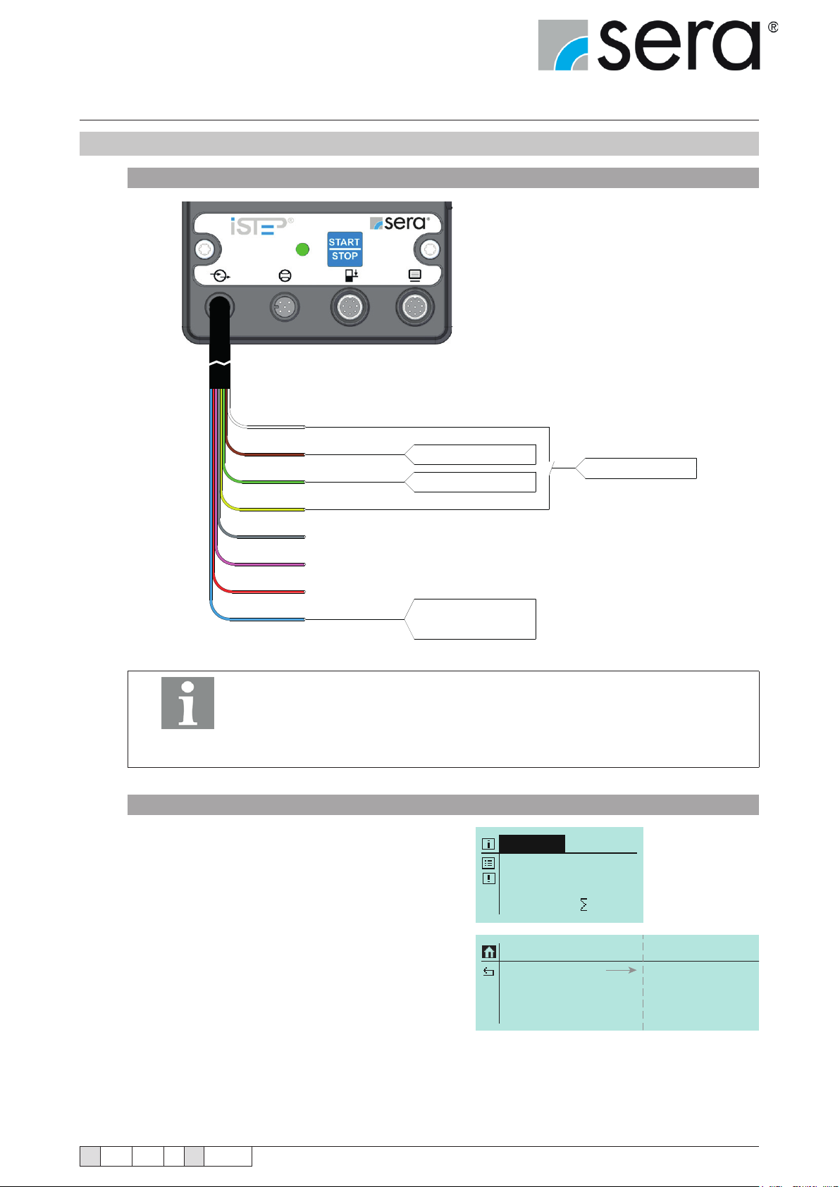
Stepper motor pump
ANALOG
PARAMETER
Signal
4-20mA
0-20mA; Adjustment
®
iSTEP
Operating Instructions
10.6.3 ANALOGUE operating mode
Connection of two analogue inputs with switching
WH
BN
GN
YE
GY
PK
RD
BN
In order to be able to use the ANALOGUE operating mode, the ANALOGUE 1
or ANALOGUE 2 function must be assigned to at least one input (see chapter
10.8.2 “Inputs 2 and 3”).
NOTE!
Selecting ANALOGUE SIGNAL
Input 3 is set as analogue input (ANALOGUE 1) at the factory.
Analogue 1/2
Analogue 1
Analogue 2
24V output
GND
mA-Signal 1(+)
Contact signal
mA-Signal 1(+)
mA-Signal 1(0)
mA-Signal 2 (-)
TA 508 Rev. 00 en 11/2015
Select ANALOG operating mode.
ANALOG
100.0 % freq.
Signal: 0-20mA
ou can select between three different analogue signals:
■ 0-20 mA
■ 4-20 mA
■ Adjustment
A signal with a control current of 4 mA corresponds to 0% stroke frequency; a signal with 20 mA corresponds to
100% stroke frequency. In this range, the stroke frequency behaves proportionally to the control current (see following gure).
Subject to technical modications!
www.sera-web.com
0 NE1: 0.00 mA
45
Page 46
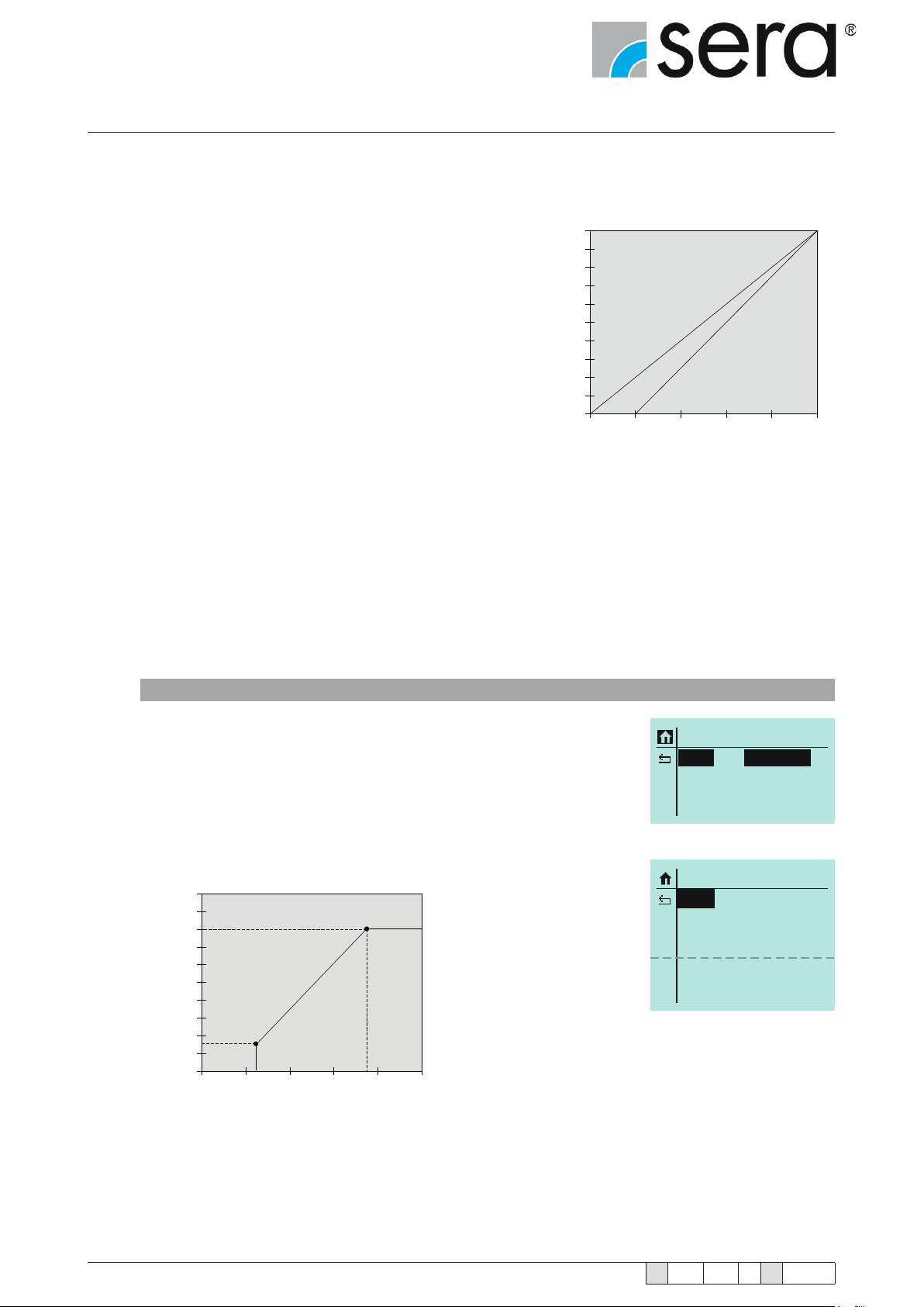
Stepper motor pump
®
iSTEP
Operating Instructions
If the input signal is < 3.5 A, the pump outputs an “Analogue signal < 4 mA” signal. Thus, a wire break (control)
current = 0 mA) can be detected. If the input signal is > 20.5 mA, the pump stops and the “Analogue
signal > 20 mA“ signal is output.
0-20 mA
0 0
8 0
A signal with a control current of 0 mA corresponds to 0%
stroke frequency; a signal with 20 mA corresponds to 100%
stroke frequency. In this range, the stroke frequency behaves proportionally to the control current (see following
gure).
6 0
4 0
2 0
Speed [%]
0 -2 0m A
4 -2 0m A
4-20 mA
A signal with a control current of 4 mA corresponds to 0%
stroke frequency; a signal with 20 mA corresponds to 100%
stroke frequency. In this range, the stroke frequency be-
0
0
4 8 1 2 1 6 2 0
Current [mA]
haves proportionally to the control current (see followinggure).
The analogue control signal can be adjusted specically for the application. For example, this is necessary if a
connected regulator provides a limited output signal.
Two points are given that reect a proportional relation between control current and stroke frequency of the pump.
In addition, these two points restrict the stroke frequency range of the pump as shown in the example in the fol-
lowing gure.
Example: Adjustment of the analogue signal
■ Point 1: 15% stroke frequency at 5 mA
■ Point 2: 80% stroke frequency at 15 mA
PARAMETER
Signal
Adjustment
If the control current is <5 mA, the stroke frequency of the pump is 0%.
If the control current is >15 mA, the stroke frequency of the pump is 80%.
100
80
60
40
Speed [%]
20
0
0
1
4 8 12 16 20
Current [mA]
2
PARAMETER
Signal
Analog I1
Frequency f1
Analog I2
Frequency f2
Adjustment
05,0 mA
000 %
15,0 mA
080 %
46
www.sera-web.com
Subject to technical modications!
TA 508 Rev. 00 en 11/2015
Page 47
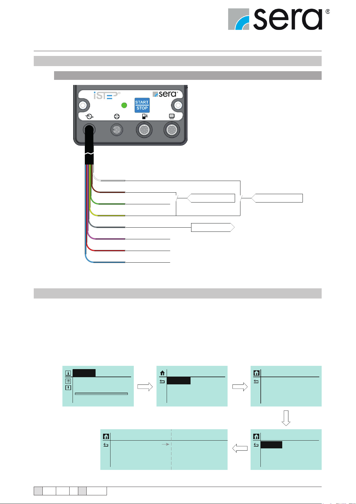
Stepper motor pump
®
iSTEP
Operating Instructions
10.6.4 BATCH operating mode
Possible connection assignment for batch mode
WH
BN
GN
YE
GY
PK
RD
BN
Start batch
External stop
Analogue 2
24V output
Batch finished
Stroke signal
Analogue outputs
GND
Contact signal
24V DC
Contact signal
10.6.4.1 ANALOGUE batch mode
Both available analogue inputs and the remaining digital input of the dosing pump are used for operation in
the Analogue batch mode.
The required batch volume is specied using one of the analogue inputs. The required maximum batch volume
is specied during the parametrisation of the pump for this. The signicance of this batch volume corresponds
to the input signal of 20 mA. All smaller input signals are linearly offset up to 4 mA with the specied maximum
volume. The batch quantity for all input signals under 4 mA is 0 litre.
BATCH
Batch 1 Manual
V: 0N
0.0 % freq. Start
TA 508 Rev. 00 en 11/2015
Batch 1
Control
Quantity
Flow R.
Subject to technical modications!
Manual
100N
0,0%
SETTINGS
Parameter
In-/Outputs
Extras
Impulse; Recipe; Analog
PARAMETER
Batch 1
Batch 2
Batch 3
PARAMETER
Batch 1
Batch 2
Batch 3
www.sera-web.com
47
Page 48
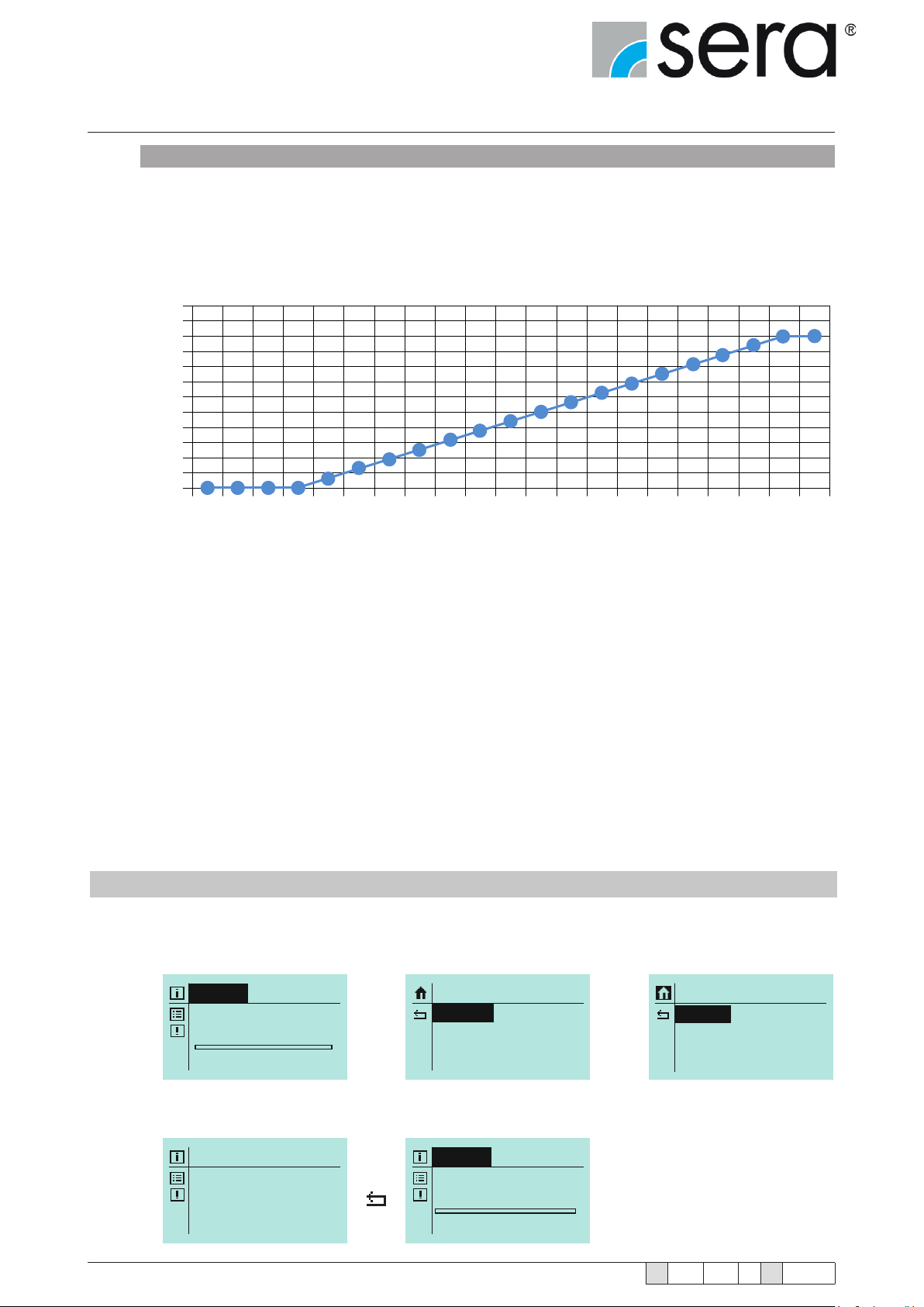
Stepper motor pump
CHARGE
®
iSTEP
Operating Instructions
Example
Specied maximum batch volume: 10 litres
Input signal: 20 mA ► batch volume: 10.0 litres
Input signal: 12 mA ► batch volume: 5.0 litres
Input signal: 4 mA ► batch volume: 0.0 litre
Input signal: 16 mA ► batch volume: 7.5 litres
12
11
10
9
8
7
6
5
4
3
2
Batch quantity (litre)
1
0
1 2 3 4 5 6 7 8 9 10 11 12 13 14 15 16 17 18 19 20 21
Input signal (mA)
The stroke speed is set in the same way as for the batch quantity. First select the maximum value that corresponds to the 20 mA signal. The delivery rate can now be set using an appropriate input signal between 4 mA
and 20 mA.
In contrast to the batch quantity, the delivery rate can also be changed during the delivery of a batch. The batch
must not be active to change the batch quantity via the input signal. The batch quantity that has been specied
using the input signal is retained at the beginning of the batch delivery. Then the input signal no longer has any
inuence on the batch quantity.
A signal at the digital input is required to start the conveying process. This signal must be maintained during
the conveying process. The current batch is cancelled if the signal is interrupted before the end of the batch
conveyance. A new batch starts when the signal is applied again.
The batch can be paused by adjusting the delivery rate.
10.6.4.2 MANUAL batch mode
For the manual batch, the batch is started, paused if necessary, and stopped directly at the pump.
One of the three batches must be adjusted in accordance with the requirement.
48
BATCH
Batch 1 Manual
V: 0N
0.0 % freq. Start
(Example: manual batch, 200 strokes (quantity N) at 50% stroke frequency)
Batch 1
Control
Quantity
Stroke Freq.
www.sera-web.com
Manual
200N
50,0%
SETTINGS
Parameter
In-/Outputs
Extras
BATCH
Batch 1 Manual
V: 200N
50,0 % freq. Start
Subject to technical modications!
PARAMETER
Batch 1
Batch 2
Batch 3
TA 508 Rev. 00 en 11/2015
Page 49
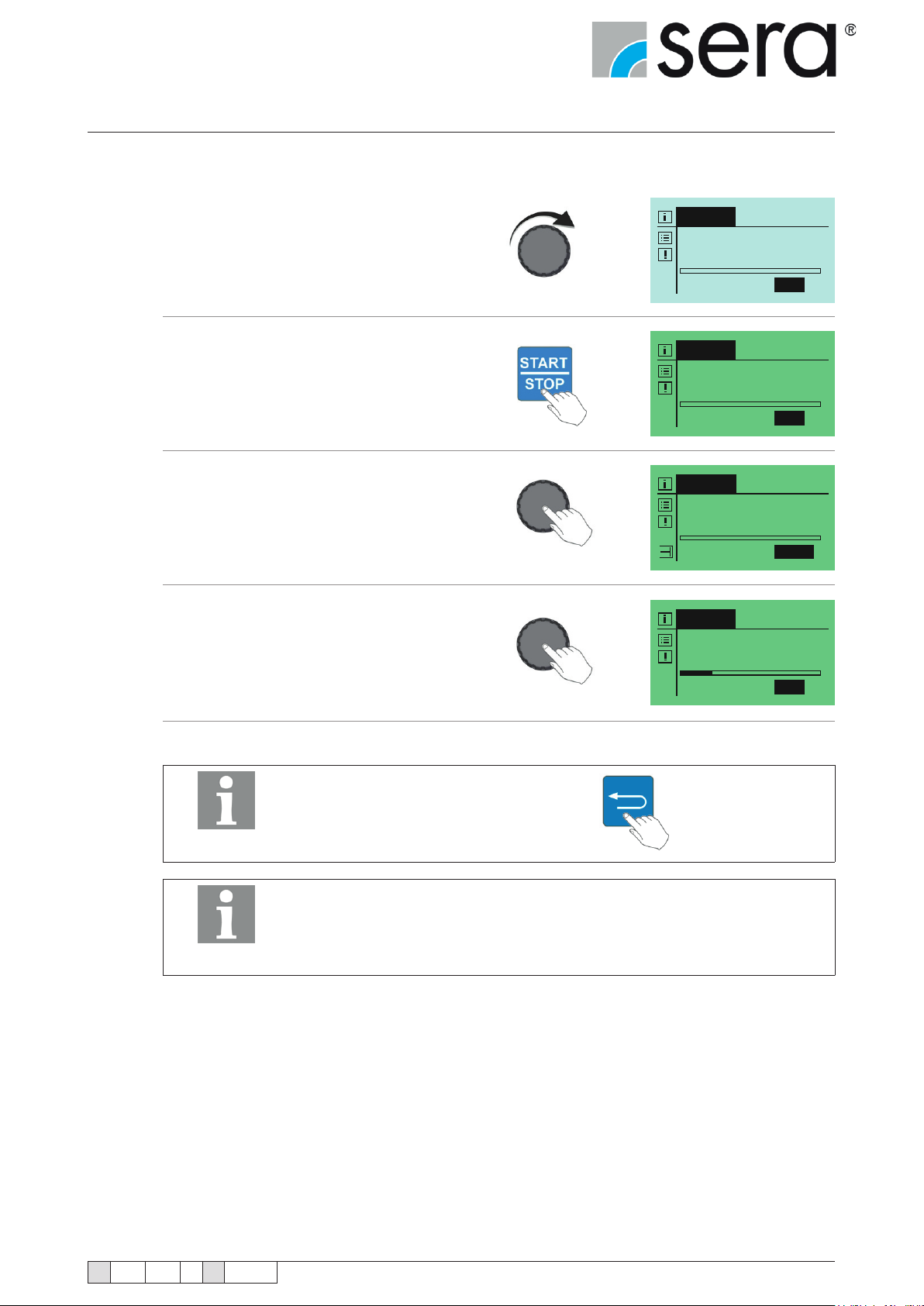
Stepper motor pump
CHARGE
®
iSTEP
Operating Instructions
Start of the manual batch:
Navigate to "Start" in the display.
Press START/STOP button on the manual control
(or on the pump case)
(display colour changes to green).
The batch can now be started using the Click wheel.
V = number of strokes of the batch
R = remaining strokes of the batch
The bar shows the progress of the batch.
BATCH
Batch 1 Manual
V: 200N
50,0 % freq. Start
BATCH
Batch 1 Manual
V: 200N
50,0 % freq. Start
BATCH
Charge 1 Manual
V: 200N R: 200N
50,0 % freq. Pause
The batch dosing can be paused by tapping
the Click wheel.
Tapping again restarts and
continues the batch dosing.
Tapping the Back button cancels the batch.
NOTE!
Signals for "remaining batch" and "batch ended" can be evaluated using ap-
propriately congured outputs (see chapter 10.8.3 "Outputs 1 and 2").
NOTE!
BATCH
Batch 1 Manual
V: 200N R: 152N
50,0 % freq. Start
TA 508 Rev. 00 en 11/2015
Subject to technical modications!
www.sera-web.com
49
Page 50
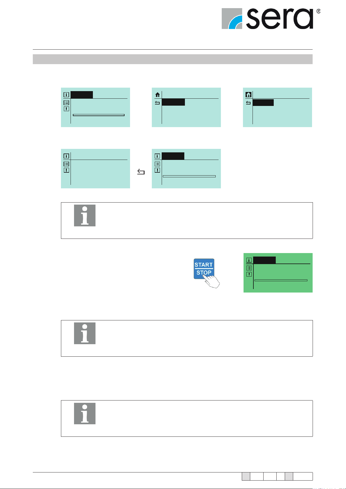
Stepper motor pump
CHARGE
®
iSTEP
Operating Instructions
10.6.4.3 PULSE batch mode
For the manual batch, the batch is started, paused if necessary, and stopped directly at the pump.
One of the three batches must be adjusted in accordance with the requirement.
BATCH
Batch 1 Manual
V: 0N
0.0 % freq. Start
(Example: pulse batch, 200 strokes (quantity N) at 50% stroke frequency)
Batch 1
Control
Quantity
Stroke Freq.
Impulse
200N
50,0%
The conguration of an input with the "Start batch" control is required for the
pulse batch mode (see chapter 10.8).
SETTINGS
Parameter
In-/Outputs
Extras
BATCH
Batch 1 Impulse
V: 200N
50,0 % freq.
NOTE!
Press START/STOP button on the manual control
(or on the pump case).
(display colour changes to green).
PARAMETER
Batch 1
Batch 2
Batch 3
BATCH
Batch 1 Impulse
V: 200N
50,0 % freq.
50
The batch now starts as soon as a pulse is received via the appropriate input.
Signals for "remaining batch" and "batch ended" can be evaluated using ap-
propriately congured outputs (see chapter 10.8.3).
NOTE!
Cancellation of the batch
The batch can be cancelled using the START/STOP buttons on the pump or by an external signal ("External
Stop").
Another input must be congured accordingly for "External stop" (see chapter
10.8).
NOTE!
www.sera-web.com
Subject to technical modications!
TA 508 Rev. 00 en 11/2015
Page 51
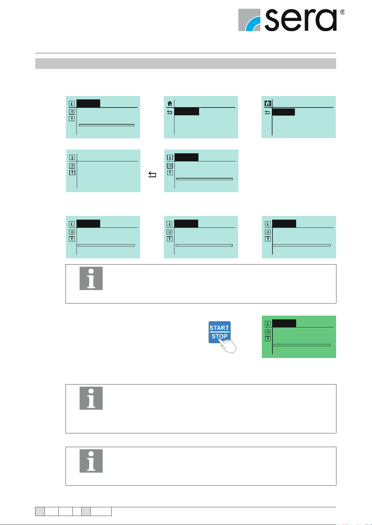
Stepper motor pump
®
iSTEP
Operating Instructions
10.6.4.4 RECIPE batch mode
Up to three batches can be programmed independently from each other in the RECIPE batch mode.
The control of the respective batch must be set to "Recipe".
BATCH
Batch 1 Manual
V: 0N
0.0 % freq. Start
Batch 1
Control
Quantity
Stroke Freq.
(Example shows three different batch settings).
Recipe
250N
80,0%
BATCH
Batch 1 Recipe
V: 250N
80,0 % freq.
The functions of the inputs must be set to "Recipe" in each case
(see chapter 10.8).
SETTINGS
Parameter
In-/Outputs
Extras
BATCH
Batch 1 Recipe
V: 250N
BATCH
Batch 2 Recipe
V: 1500N
50,0 % freq.
80,0 % freq.
PARAMETER
Batch 1
Batch 2
Batch 3
BATCH
Batch 3 Recipe
V: 50N
77,5 % freq.
NOTE!
Press START/STOP button on the manual control
(or on the pump case).
(display colour changes to green).
The respective batch now starts as soon as a signal is received via the appropriate input.
The input signal must be present continuously - the current batch is cancelled as soon as the signal is no longer present.
Input 1 starts batch 1
NOTE!
NOTE!
Input 2 starts batch 2
Input 3 starts batch 3
Incoming signals during the batch dosing are
not buffered.
The repetition of any batch (or the start of another batch)
cannot be performed until after completion of the running batch.
BATCH
Batch 1 Recipe
V: 250N
80,0 % freq.
TA 508 Rev. 00 en 11/2015
Subject to technical modications!
www.sera-web.com
51
Page 52
Stepper motor pump
®
iSTEP
Operating Instructions
Cancellation of the batch during the batch dosing
■ can be performed using the START/STOP buttons on the pump
■ is performed by interruption of the input signal
NOTE!
Signals for "remaining batch" and "batch ended" can be evaluated using ap-
propriately congured outputs (see chapter 10.8.3).
52
www.sera-web.com
Subject to technical modications!
TA 508 Rev. 00 en 11/2015
Page 53
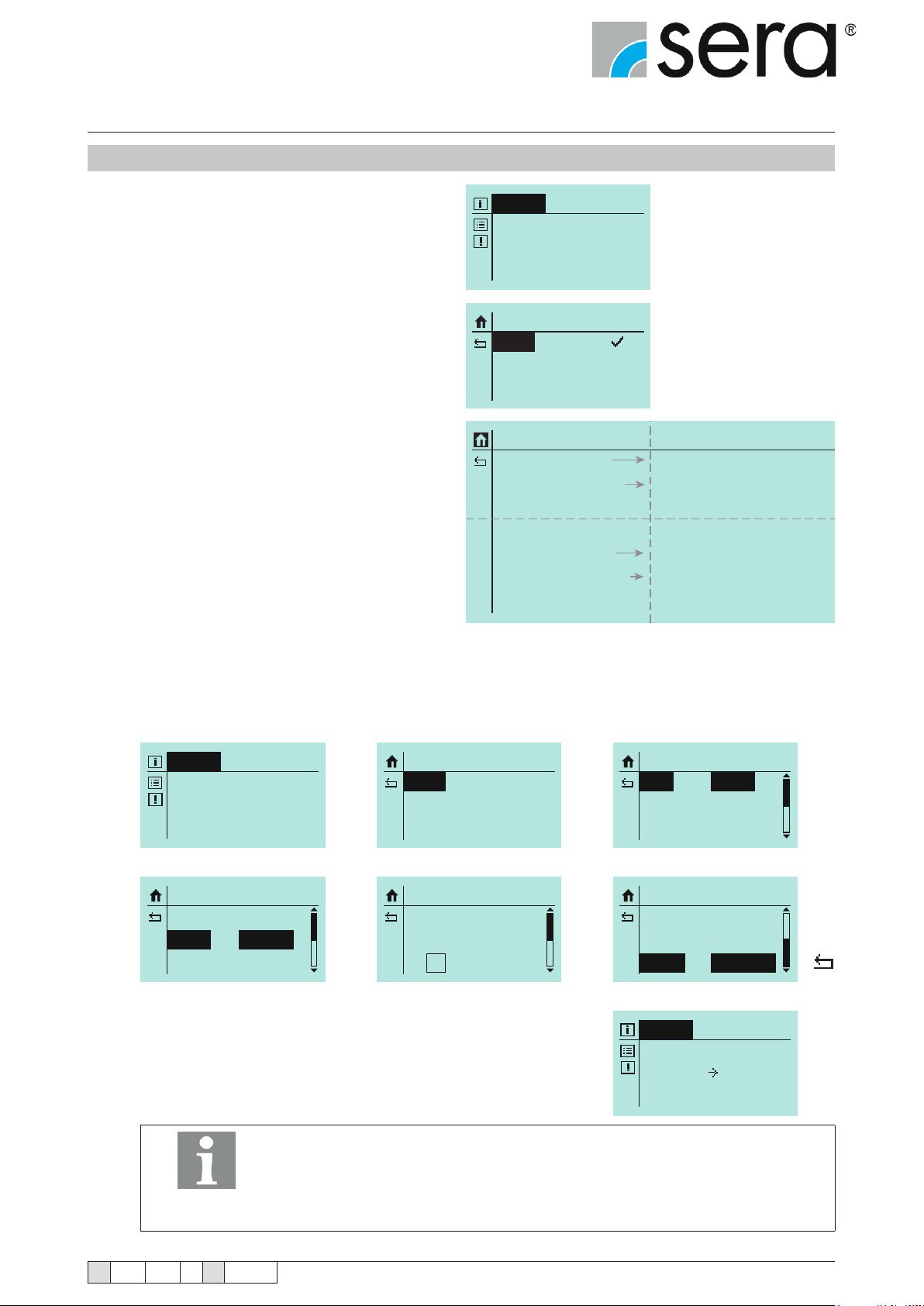
Stepper motor pump
®
iSTEP
Operating Instructions
10.6.5 TIMER operating mode
Select TIMER operating mode.
There are 10 independent timers
available.
The timers enable batch dosing where a batch
begins at a specied time or any time-controlled
ACTIVATION and DEACTIVATION of the pump.
A stroke frequency can be assigned to each timer.
An interval of consecutive days (Mon-Fri, MonSun, Sat-Sun) or individual days of the week can
be assigned to the timers.
TIMER
No Timer chosen!
PARAMETER
Timer 1
Timer ....
Timer 10
Timer 1
Mode
Interval
Period
Start
End
Batch:
Flow R.
OFF
Daily
Mo-Su
00:00
00:00
V: ON
0,0 % freq.
Manual; Batch
Weekday
Mo-Fr; Sa-Su
at Mode “OFF” and “Manual”
at Mode “Batch”
Example:
Manual dosing (at 50% stroke frequency) should be performed on a weekday (Tuesday)
from 10:00 to 10:30 in each case.
Process
TIMER
No Timer chosen!
Timer 1
Mode
Interval
Period
Manual
Weekday
Mo-Fr
PARAMETER
Timer 1
Timer 2
Timer 3
Timer 1
Mode
Interval
Mo Tu We Th Fr Sa Su
Manual
Weekday
Timer 1
Mode
Interval
Period
Timer 1
Start
End
Flow R.
TIMER
Next: Timer 1
Tu 10:00 Tu 10:30
Q: 50,0% freq.
Manual
Daily
Mo-Fr
10:00
10:30
50,0% freq.
NOTE!
TA 508 Rev. 00 en 11/2015
Any possible overlapping of specied time periods is prevented
(an appropriate message is shown on the display).
Subject to technical modications!
www.sera-web.com
53
Page 54
Stepper motor pump
®
iSTEP
Operating Instructions
10.7 Settings (parameters)
The following table shows the factory settings for the stepper motor pump. Standard applications such as manual
operation, analogue operation with 4-20 mA, 1/1 pulse operation and external operation with external ON are possible
without having to make further settings.
The references to the respective chapters facilitate the adjustment of the settings. Furthermore, the parameters table
provides the possibility to document the changes that have been made in the settings.
Overview of set parameters
Factory
setting
Pulse operation
Pulse memory ON
Pulse mode 1:1
Pulse factor 1/1
Analogue operation
Signal 4-20 mA
Batch operation
Control manual
Quantity 0
Frequency 0
Input 1
Function E1 Pulse
Contact E1
Normally open
contact
Input 2
Function E2 External stop
Contact E2
Normally closed
contact
Input 3
Function E3 Analogue 2
Contact E3
Normally open
contact
Output 1
Function A1 Group fault
Contact A1
Normally closed
contact
Output 2
Function A2 Stroke signal
Contact A2
Normally open
contact
Analogue output
Function Analogue input
Signal -
Dosing monitoring
Sensor OFF
Function Warning
Faulty strokes 10
Alarm limit 80%
Level
Pre-alarm
Dry run
Normally open
contact
Normally open
contact
Chapter Change Change
System
Language Deutsch
Display
Display refresh 1 h
Contrast 100%
SD card
Signals YES
Operating data YES
Write period 10 min
Time
Date
Time
Password
PW01 mode OFF
PW02 mode ON
Password 01 9990
Password 02 9021
Maintenance
Factory setting
Slow mode
Suction stroke 100%
Diaphragm monitoring
Input signal ON
Sensitivity 50%
Venting
Control OFF
Venting time 10 sec.
Cycle time 40 min
(1)
Calibration
Active NO
Strokes 200
Speed 80%
(1)
Option
Factory
setting
set date
set time
Chapter Change Change
54
www.sera-web.com
Subject to technical modications!
TA 508 Rev. 00 en 11/2015
Page 55
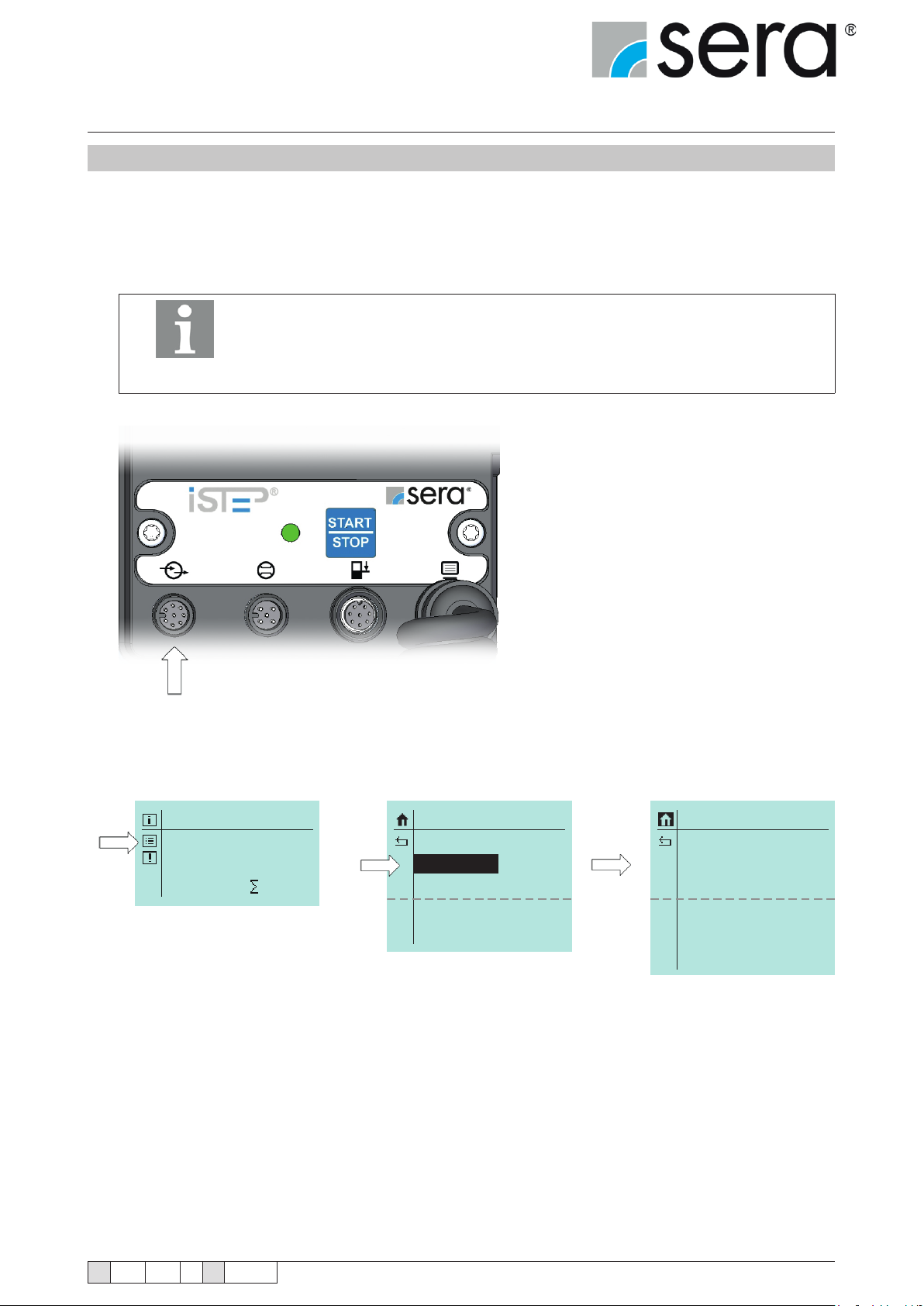
Stepper motor pump
®
iSTEP
Operating Instructions
10.8 Inputs/outputs
The pump is equipped with three inputs and three outputs that can be variably congured via a menu in accordance
with the respective operating conditions.
It is possible to assign the same functions to all three inputs.
If several inputs are congured identically, the input signals will be evaluated via
OR operation.
This means that the function will be performed as soon as any of the inputs fulls
NOTE!
the condition.
Inputs and outputs
(see chapter 7.2.1 for pin assignments)
MANUAL
100.0 % freq.
0 N
SETTINGS
Parameter
In-/Outputs
Extras
System
Calibration
IN/OUTPUTS
Input 1
Input 2
Input 3
Output 1
Output 2
Analog Output
TA 508 Rev. 00 en 11/2015
Subject to technical modications!
www.sera-web.com
55
Page 56
Stepper motor pump
MANUELL
®
iSTEP
Operating Instructions
10.8.1 Input 1 (digital)
One of six different functions can be assigned to input 1.
Optionally, a switch off is also possible.
Input 1
Function:
Contact:
OFF
Extern Stop
De-Aeration
Impulse
Analog 1/2
Recipe
Batch Start
NO
NC
Function
OFF
No function is assigned to the input.
External stop
Function for stopping the pump externally
The External stop
symbol is shown in
the display if the pump
is stopped using Ex-
NOTE!
Venting
Function for external control of the automatic ventilation device (optional accessory).
Impulse
Conguration of the input as pulse input
Analogue 1/2
This function is used for switching between the two analogue inputs.
Analogue 1 and Analogue 2 (inputs 2 and 3) via Input 01.
The analogue input is selected according to the table.
ternal stop
MANUAL
100.0 % freq.
0 N
Switching analogue input
Conguration contact E1 Applied signal Selected analogue input
NORMALLY CLOSED CONTACT High Analogue 1 (Input 2)
NORMALLY CLOSED CONTACT Low Analogue 2 (Input 3)
NORMALLY OPEN CONTACT High Analogue 2 (Input 3)
NORMALLY OPEN CONTACT Low Analogue 1 (Input 2)
Recipe
Conguration of the input for the batch recipe selection operating mode
Batch Start
Function for starting the batch externally
Contact
Normally open contact Conguration of the contact type (NC or NO).
Normally closed contact
56
www.sera-web.com
Subject to technical modications!
TA 508 Rev. 00 en 11/2015
Page 57
Stepper motor pump
MANUELL
®
iSTEP
Operating Instructions
10.8.2 Inputs 2 and 3 (digital/analogue)
Basically, input 2 and input 3 have the same functions as input 1. Furthermore, they can be used as analogue inputs (Analogue 1/Analogue 2/Batch quantity/Batch speed). However, the function “Analogue 1/2” which is used to
switch over between the analogue inputs is not available. In addition, it is possible to congure the contact signals
of the inputs as NC or NO (not relevant for analogue).
Input 2
Function:
Contact:
Input 3
Function:
Contact:
OFF
Extern Stop
De-Aeration
Impulse
Analog 1
Recipe
Batch Start
Batch Volume
Batch Speed
NO
NC
OFF
Extern Stop
De-Aeration
Impulse
Analog 2
Recipe
Batch Start
Batch Volume
Batch Speed
NO
NC
Function
OFF
No function is assigned to the input.
External stop
Function for stopping the pump externally
The External stop
symbol is shown in
the display if the pump
is stopped using Ex-
NOTE!
Venting
Function for external control of the automatic ventilation device (optional accessory).
Impulse
Conguration of the input as pulse input
Analogue 1 (for Input 2) and Analogue 2 (for Input 3)
The respective input is congured as an analogue input.
ternal stop
MANUAL
100.0 % freq.
0 N
If the inputs 2 and 3 are congured as analogue inputs,
the changeover between these two analogue inputs is
made via Input 1 (function: Analogue 1/2)
NOTE!
Recipe
Conguration of the input for the Batch recipe selection operating mode
Batch Start
Function for starting the batch externally
Batch Volume
Function for specication of the batch volume (quantity)
(20 mA corresponds to the value set under Batch parameters)
Batch Speed
Function for specication of the batch speed
(20 mA corresponds to the value set under Batch parameters)
Contact
Normally open contact Conguration of the contact type (NC or NO).
Normally closed contact
TA 508 Rev. 00 en 11/2015
Subject to technical modications!
www.sera-web.com
57
Page 58

Stepper motor pump
®
iSTEP
Operating Instructions
10.8.3 Outputs 1 and 2 (digital)
Each of the outputs 1 and 2 can be assigned one of twelve different functions
(the functions are identical for both outputs).
Optionally, a switch off is also possible.
It is also possible to congure the contact signals of the outputs as NC or NO.
Output 1
Output 2
Function:
Contact:
OFF
Ready to Run
Pump Active
Stroke Signal
Pre-Alarm Lev.
Dry-Running
Diaphr. Rupt.
No Flow
Coll. Signal
Coll. Fault
Internal Error
Batch Finished
NO
NC
Function
OFF
No function is assigned to the output.
Ready to Run
Signal for operational readiness of the stepped motor pump.
Pump Active
Pump is in operation.
Stroke Signal
Signal for execution of a stroke.
Pre-Alarm Lev. (level pre-alarm)
Signal of the pre-alarm for two-stage level monitoring.
Dry-Running
Signal of the dry running for level monitoring.
Diaphr. Rupt (Diaphragm rupture)
Signal of a diaphragm rupture for diaphragm rupture monitoring.
No Flow
With activated ow control, signal indicating that the permitted number of fault strokes
for fault monitoring has been exceeded.
Coll. signal (Collective signal)
Signal indicating that any of the following faults has occurred:
■ All faults of the collective fault
■ Pre-alarm level
■ No ow (for MESSAGE function)
Coll. fault (Collective fault)
Signal indicating that any of the following faults has occurred:
■ Diaphragm rupture
■ Dry run
■ Internal error
■ No ow
Int. Error (Internal error)
Signal indicating that any of the following faults has occurred:
■ Fault drive
■ Fault stroke sensor
■ No stroke detection
■ Setpoint cannot be achieved
(see chapter 13 "Troubleshooting and fault clearance") for fault descriptions / causes
Batch Finished
Signal of the end of batch for batch operating mode.
58
www.sera-web.com
Contact
Normally open contact Conguration of the contact type (NC or NO).
Normally closed contact
Subject to technical modications!
TA 508 Rev. 00 en 11/2015
Page 59
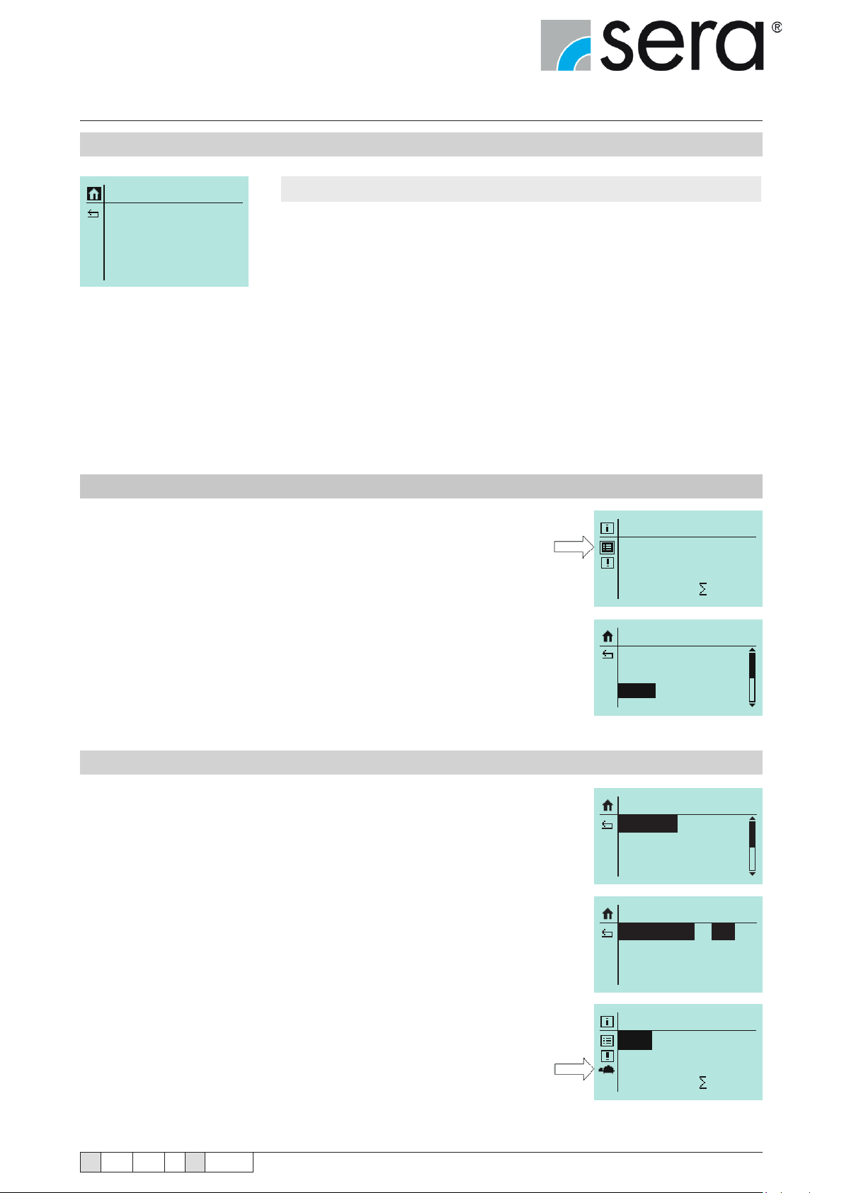
Stepper motor pump
Manuell
®
iSTEP
Operating Instructions
10.8.4 Analogue output
Analog output
Function:
Contact:
Stroke Freq.
A. Input
Rem. Batch
NO
NC
Function
Stroke Freq. (stroke frequency)
Output of a current depending on the stroke frequency.
Can be output as signal 0-20 mA, 4-20 mA and standardised.
A. Input (analogue input)
The current present at the analogue input is output again 1 to 1
Rem. Batch (remaining batch)
Output of a current depending on the remaining batch. The larger the percentage
of the remaining batch to the total batch the larger is the output current
Example:
Batch quantity: 10 l, remaining batch 7.5 l=>75% still to convey
Mode: 0-20 mA > output current 75% of 20 mA=> 15 mA
10.9 Extras
■ Select Settings icon (arrow).
■ Select "Extras".
The extras settings are independent from the operating mode.
■ Slow mode
■ Speed limit
■ Dosing monitor
■ Diaphragm monitor
■ Level
■ Venting
Manual
100.0 % freq.
0 N
SETTINGS
Parameter
In-/Outputs
Extras
10.9.1 Slow mode
In Slow mode, the pump is operated at reduced speed in the suction
stroke.
This is useful, for example, if media with high viscosity are to be conveyed.
The speed of the suction stroke can be set to 75, 50 or 25% of the normal
suction stroke speed.
Due to the reduced suction stroke speed, the maximum congurable delivery quantity reduces (see "Technical data").
The Slow mode symbol (arrow) is shown on the Home display.
TA 508 Rev. 00 en 11/2015
Subject to technical modications!
EXTRAS
Slow-Mode
Speed Limit
Dosing Monitor
Slow-Mode
Suction Stroke
Manual
41.2 % freq.
www.sera-web.com
50%
0 N
59
Page 60
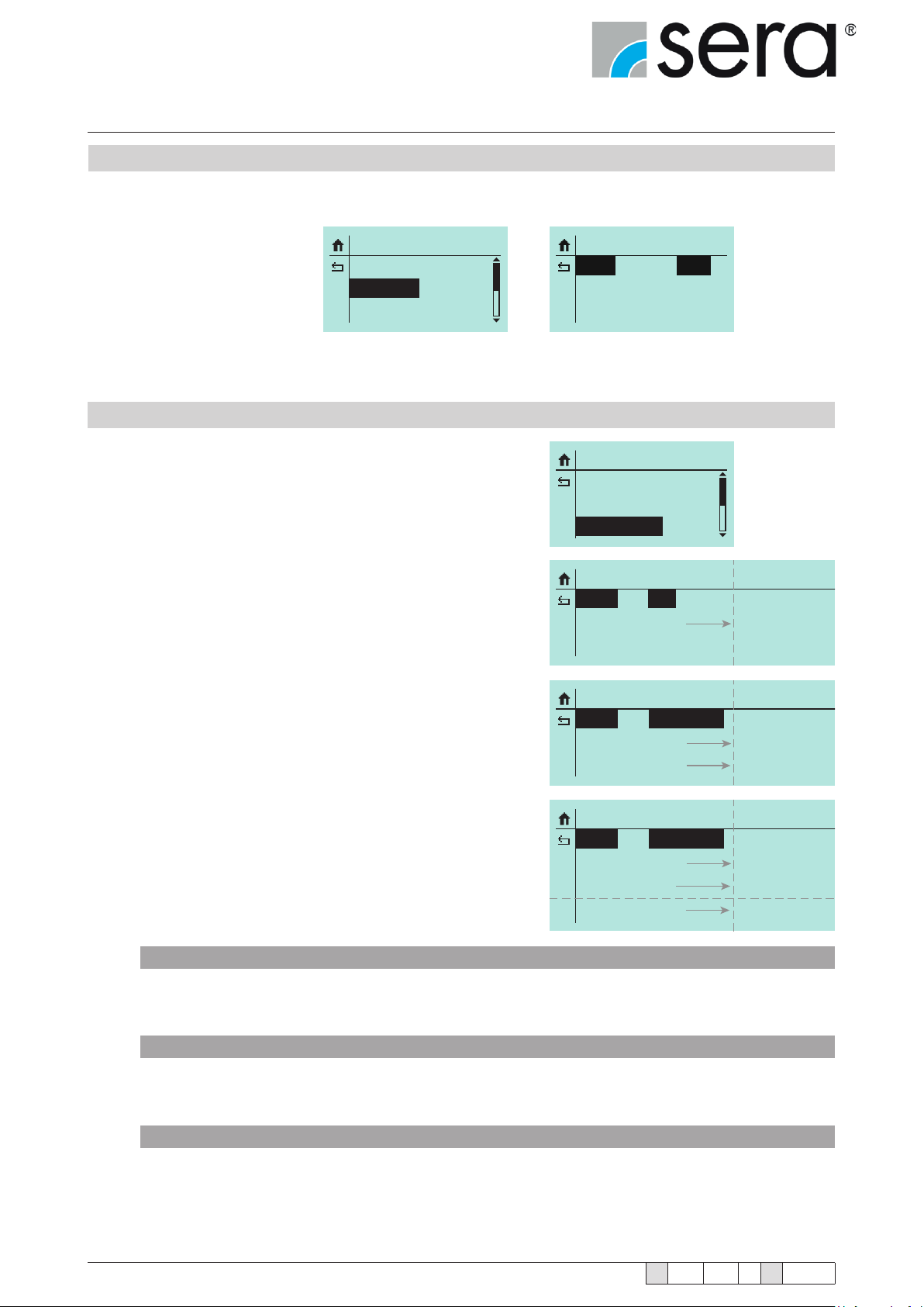
Stepper motor pump
®
iSTEP
Operating Instructions
10.9.2 Speed limit
The maximum congurable speed of the pump in operation can be limited (30-100%).
EXTRAS
Slow-Mode
Speed Limit
Dosing Monitor
10.9.3 Dosing monitor
The connection of a sera ow monitor to the dosing pump ena-
bles monitoring of the ow rate of the dosing pump.
The connection of a sera ow meter to the dosing pump pro-
vides a more detailed ow rate indication with regulation of the
ow rate.
The following items can be adjusted:
■ Sensor
■ Function
■ Fault strokes
■ Alarm limit
Speed Limit
Speed 100%
EXTRAS
Slow-Mode
Speed Limit
Dosing Monitor
Dosing Monitor
Sensor
Function
OFF
Stop
Message
Dosing Monitor
Sensor
Function
Fault Stroke
TYPE 819x.1
Stop
010
Message
001 ... 100
Dosing Monitor
Sensor
Function
Fault Stroke
Alarm Limit
SENSOR
Selection of a connected sera ow monitor (type 819x.1)
or sera ow meter (type 801x.1).
FUNCTION
Selection of the dosing monitoring function. It can be selected whether the dosing monitoring should trigger a
warning message (WARNING) or a switch-off of the pump (PUMP STOP).
FAULT STROKES
TYPE 801x.1
Stop
010
080%
Message
001 ... 100
001% ... 100%
60
Number of fault strokes at which a connected ow monitor triggers the dosing monitor.
The factory setting is 10 fault strokes. This means that the dosing monitoring will react if the ow monitor does not
give a stroke conrmation to the pump for the duration of ten consecutive strokes.
www.sera-web.com
Subject to technical modications!
TA 508 Rev. 00 en 11/2015
Page 61
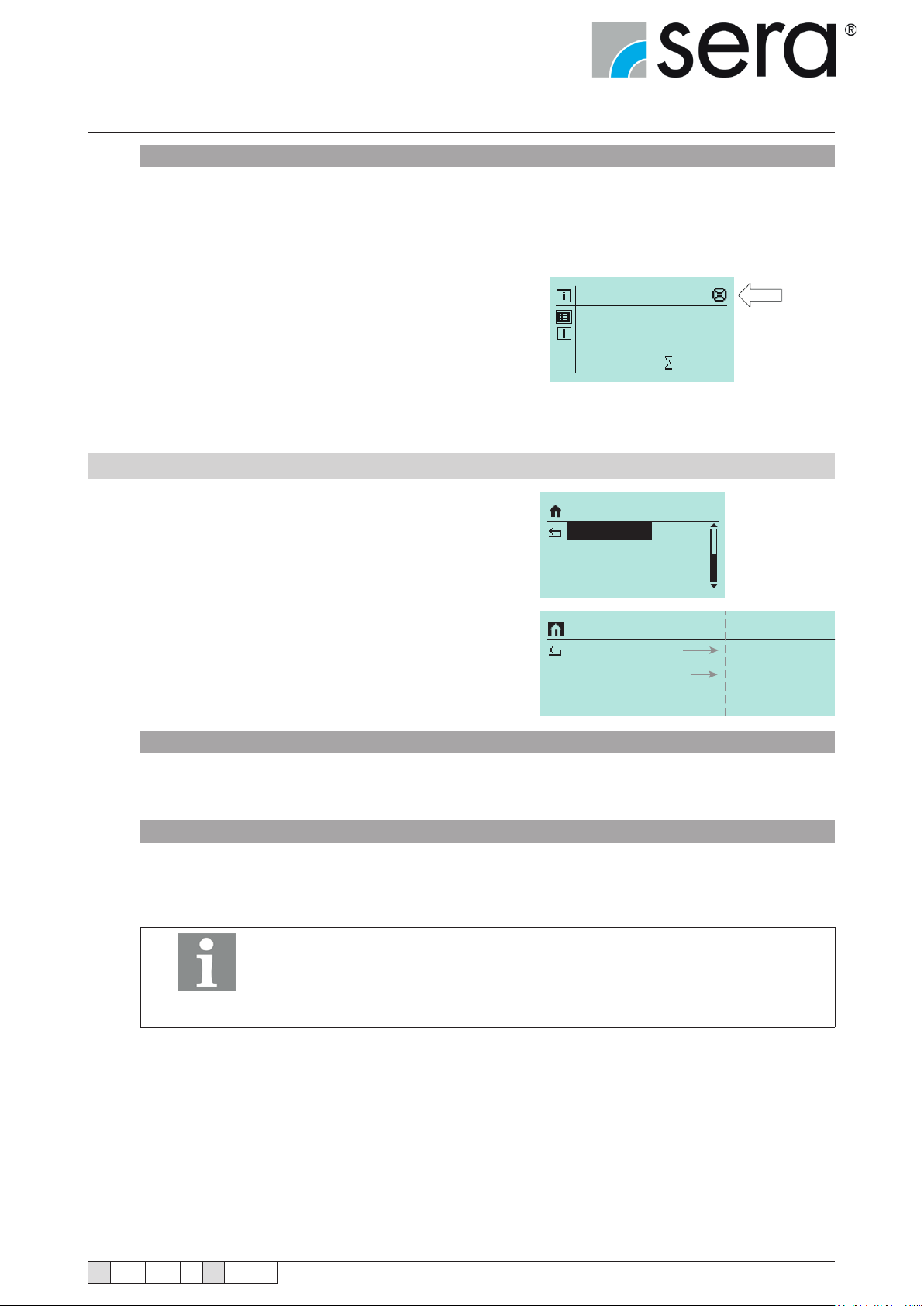
Stepper motor pump
®
iSTEP
Operating Instructions
ALARM LIMIT
Alarm limit at which a connected ow meter triggers the dosing monitor. The entered value corresponds to the
percentage part of the setpoint ow rate.
The factory setting is 80%. This means that the dosing monitor will react if a connected ow meter measures a ow
rate which is lower than 80% of the setpoint ow rate.
After the adjustment, the symbol for the ow rate measure-
ment (arrow) is shown on the Home display.
10.9.4 Diaphragm monitor
Diaphragm rupture detection is installed in every stepped motor
pump. It is used for monitoring the delivery diaphragm.
The following items can be adjusted:
■ Input signal
■ Sensitivity
Manual
100.0 % freq.
0 N
EXTRAS
Diaph. Monitor
Level
De-Aeration
Diaph. Monitor
Input Signal
Sensitivity
OFF
050%
NC; NO
001% ... 100%
INPUT SIGNAL
Selection between switch off (OFF) of the diaphragm rupture electrode and a conguration as
ON or OFF.
SENSITIVITY
Input of the sensitivity of the diaphragm rupture electrode in percent. This enables adaptation to the conductivity
of the pumped medium. In the case of poorly conductive media, the sensitivity must be set to a high value (e.g.
100% at approx. 4 µS/cm).
The sensitivity is set to 50% at the factory. This corresponds to a minimum
conductivity of the dosing medium of approx. 10 µS/cm.
The minimum conductivity at 100% sensitivity is 4 µS/cm.
NOTE!
TA 508 Rev. 00 en 11/2015
Subject to technical modications!
www.sera-web.com
61
Page 62
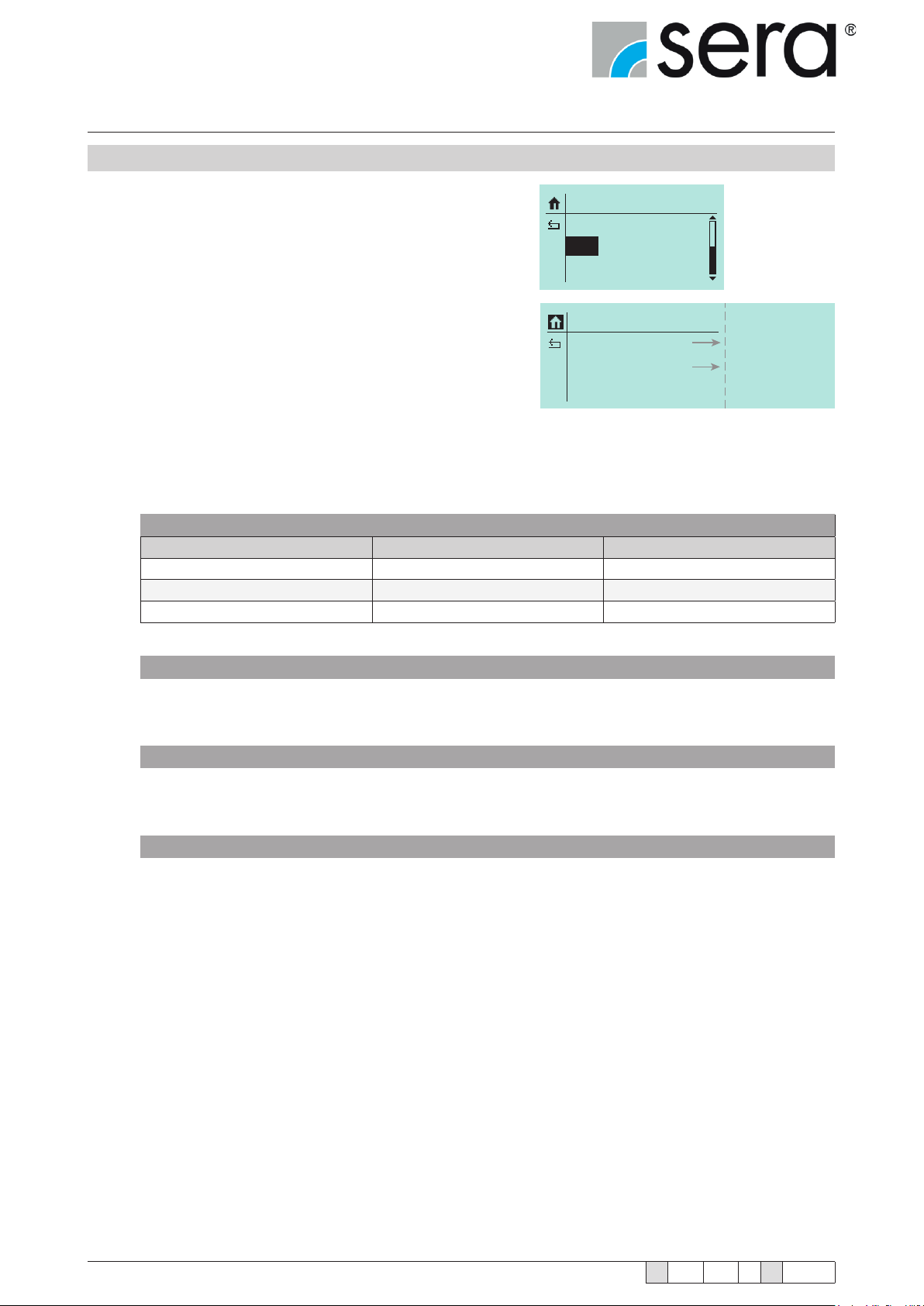
Stepper motor pump
®
iSTEP
Operating Instructions
10.9.5 Level
The connection of a sera suction lance enables the monitoring
of the ll level of the dosing tank:
The following items can be adjusted:
■ Pre-alarm
■ Dry run
EXTRAS
Diaph. Monitor
Level
De-Aeration
Level
Pre-Alarm
Dry-Running
Conguration of the two level inputs. It can be selected between either the switch off (OFF) of the input and a
conguration as NC (normally closed oating contact) or NO (normally open oating contact).
The factory setting for both level inputs is NO.
Conguration of the level input
Conguration Pre-alarm Dry run
1 NORMALLY OPEN CONTACT NORMALLY OPEN CONTACT
2 NORMALLY OPEN CONTACT NORMALLY CLOSED CONTACT
3 NORMALLY CLOSED CONTACT NORMALLY CLOSED CONTACT
OFF
OFF
NC; NO
NC; NO
Conguration 1
This conguration is preset at the factory. A 1-stage or 2-stage level monitor with oating normally open contacts
(pre-alarm + dry run or only dry run) can be connected.
Conguration 2
This conguration must be selected if a 1-stage level monitor (dry run only) with oating normally closed contact
is connected.
Conguration 3
This conguration must be selected if a 2-stage level monitor with oating normally closed contacts (pre-alarm +
dry run) is connected.
62
www.sera-web.com
Subject to technical modications!
TA 508 Rev. 00 en 11/2015
Page 63
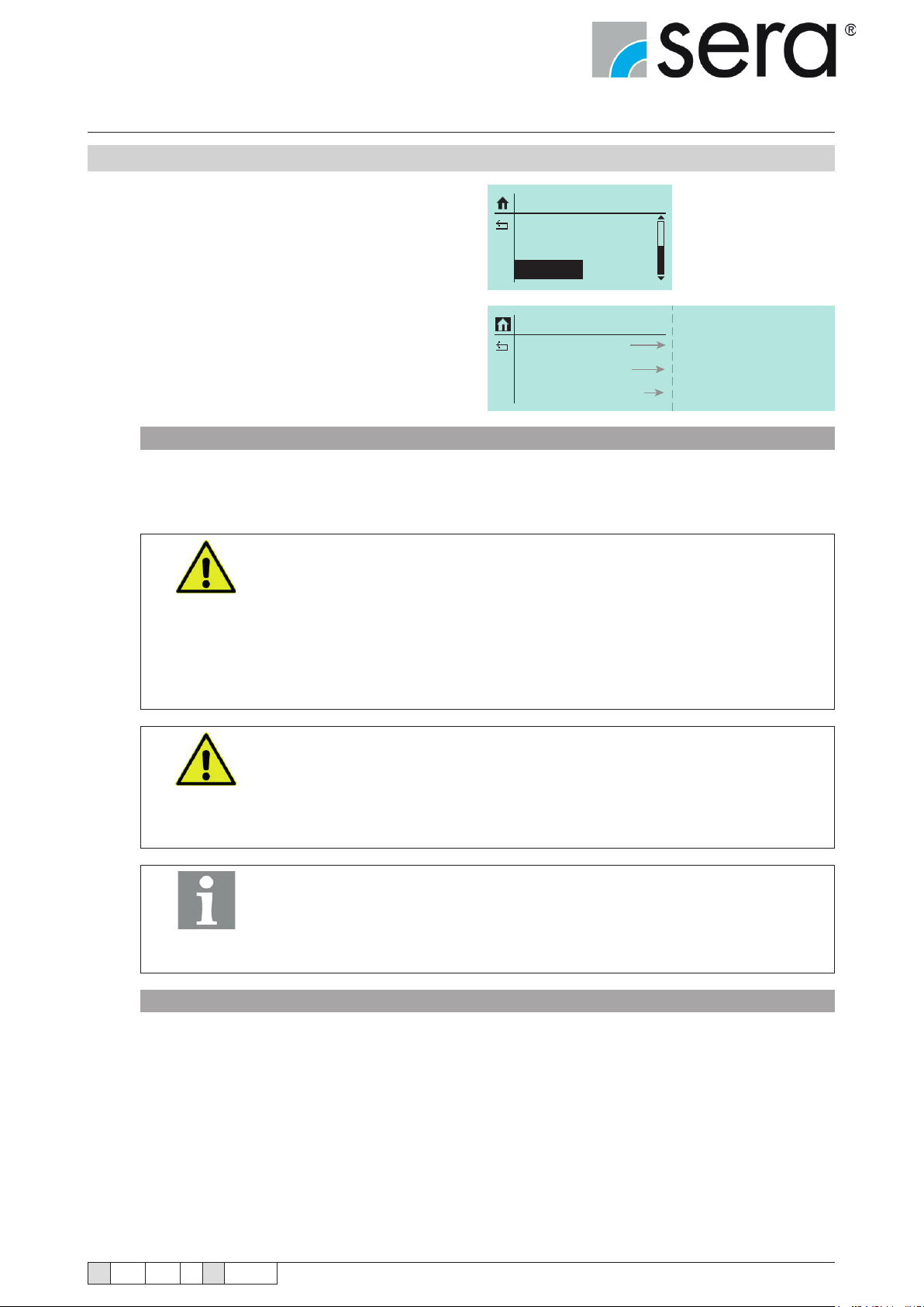
Stepper motor pump
®
iSTEP
Operating Instructions
10.9.6 Venting
The dosing pump can optionally be equipped with an
automatic ventilation device that is controlled directly
by the control electronics of the dosing pump.
The following items can be adjusted:
■ Control
■ Venting time
■ Cycle time
CONTROL
Selection of the type of control for triggering the venting process. The venting can either be triggered via an external signal (EXTERNAL), after a preset interval time (INTERVAL), or automatically when (re)starting the pump after
at least 30 minutes of inactivity (AUTOMATIC). A switch-off (OFF) is also possible.
In addition to the congurable type of control, manual venting is also possible
at any time:
Go to the operating message “VENTING: OFF” and press the ENTER button
ATTENTION!
– then, the venting will be active (“VENTING: ON") until the ENTER button is
pressed again or the maximum venting time of 5 minutes is reached.
EXTRAS
Diaph. Monitor
Level
De-Aeration
De-Aeration
Control
De-Aerat.Time
Interval Time
OFF
010s
040min
Extern; Interval; Automatic
005s ... 300s
15min ...100min
The venting can be started again after expiry of the minimum interval time of 15
minutes.
After pump and suction line have been vented, there might be the possibility
(depending on the backpressure) that small liquid quantities are already conveyed into the pressure line although the vent valve is still open.
ATTENTION!
NOTE!
VENTING TIME
Input of the venting time in seconds. During each venting process, the vent valve will be opened for this time.
The factory setting is 10 sec. (value range: 5 – 300 sec.).
The venting period must therefore be coordinated with the possible gas volume
on the suction side of the pump.
The maximum venting time is limited to 5 minutes in all operating modes of
the venting. The minimum interval time after which the venting can be started
again is 15 minutes.
In the case of control via external signals, the specied time limits must be
complied with.
TA 508 Rev. 00 en 11/2015
Subject to technical modications!
www.sera-web.com
63
Page 64
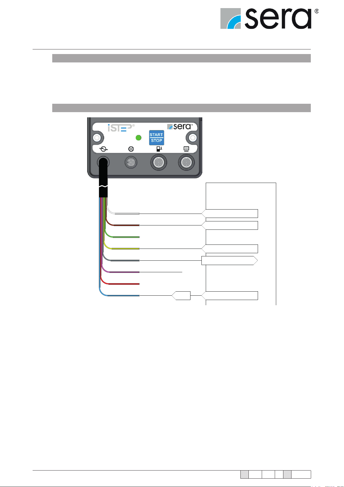
Stepper motor pump
®
iSTEP
Operating Instructions
INTERVAL TIME
Input of the interval time in minutes at which the venting is repeated (with INTERVAL control).
The factory setting is 40 min. (value range: 15 to 100 min.).
Possible pin assignment for external control of the automatic ventilation device with a PLC
WH
BN
GN
YE
GY
PK
RD
BN
Venting
External Stop
Collective fault
Stroke signal
GND
0V
Programmable Logic
Control (PLC)
24V DC (output)
24V DC (output)
24V DC
Input
0V (Ground)
64
www.sera-web.com
Subject to technical modications!
TA 508 Rev. 00 en 11/2015
Page 65
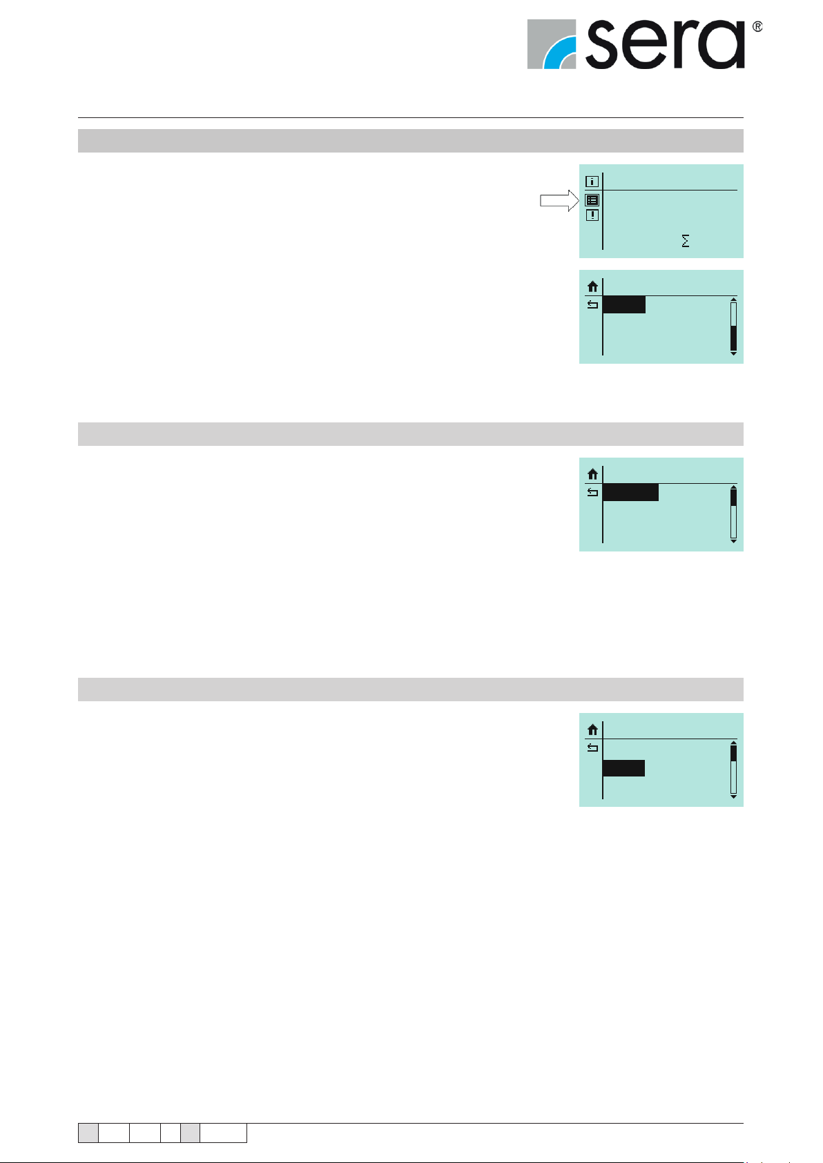
Stepper motor pump
Manuell
®
iSTEP
Operating Instructions
10.10 SYSTEM
■ Select Settings icon (see arrow).
■ Select "System".
The system settings are independent from the operating mode.
■ Language
■ Display
■ SD card
■ Time
■ Password
■ Maintenance
■ Data transfer
■ Factory setting
10.10.1 Language
You can select between 9 languages as menu languages.
■ German
■ English
■ Spanish
■ French
■ Dutch
■ Czech
■ Finnish
■ Turkish
■ Swedish
Manual
100.0 % freq.
0 N
SETTINGS
System
Calibration
SYSTEM
Language
Display
SD-Card
10.10.2 Display
Display refresh
Cycles of the display refresh
■ 1 min
■ 30 min
■ 1 h
■ 10 h
■ 24 h
Contrast
■ 0-100%
Volume unit
■ Display of the units in the metric system or US gallons
SYSTEM
Language
Display
SD-Card
TA 508 Rev. 00 en 11/2015
Subject to technical modications!
www.sera-web.com
65
Page 66
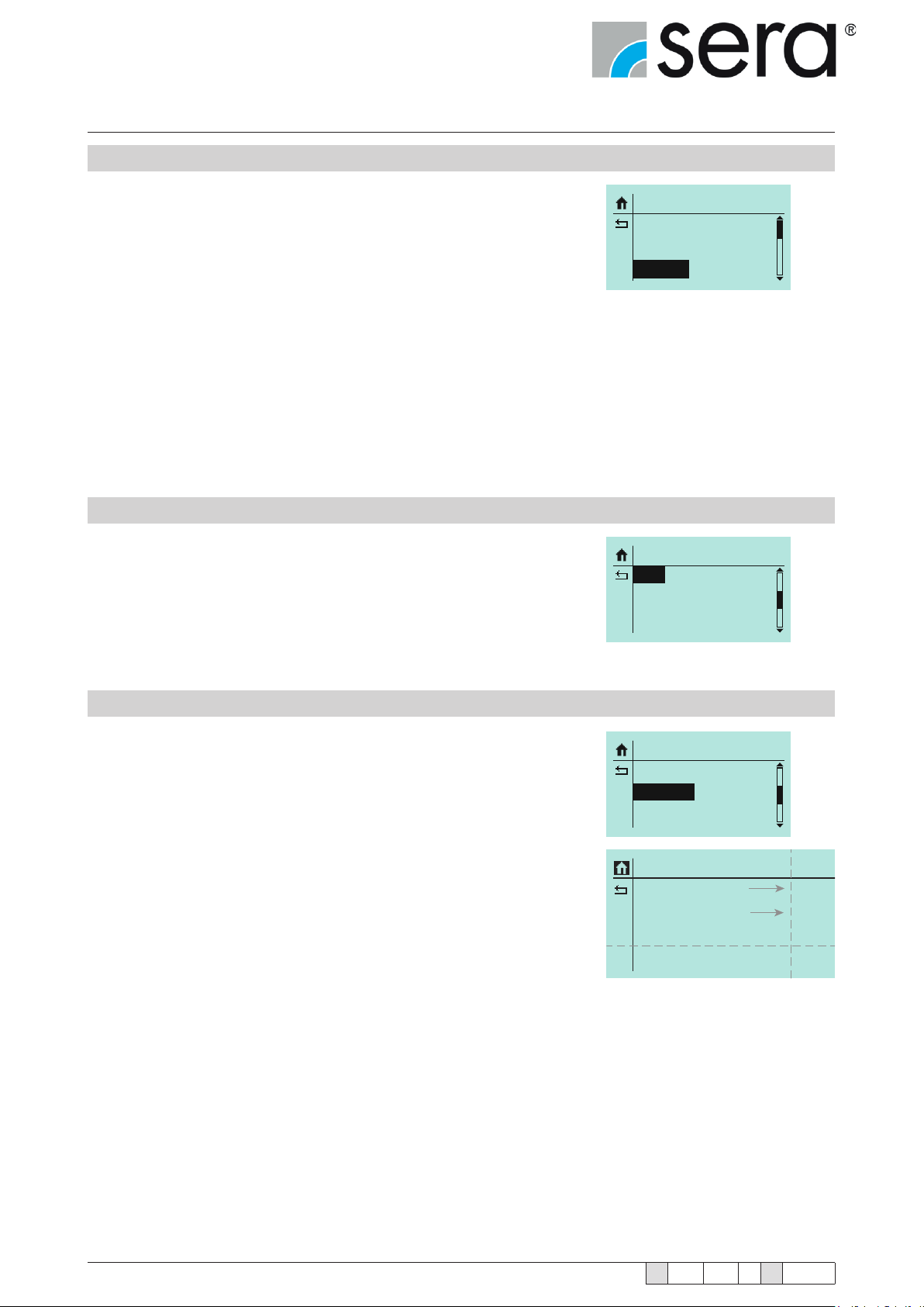
Stepper motor pump
®
iSTEP
Operating Instructions
10.10.3 SD Card
Selection for what should be logged on the SD card.
Messages
If any message occurs, this is logged on the card with the time
Operating data
Delivery quantity, operating mode, settings of INPUTS/OUTPUTS, operating mode dependent data (e.g. analogue current).
Write period
■ 1 min
■ 5 min
■ 10 min
■ 30 min
10.10.4 Time
Setting of date and time.
Time format
■ 0-24 h
■ 0-12 h am/pm
SYSTEM
Language
Display
SD-Card
SYSTEM
Time
Password
Maintenance
10.10.5 Password
Two password levels are provided to increase the operating safety. The
passwords for these levels consist of a four-digit numeric code and are
freely selectable.
Password 1 9990 (PW1) is used to protect the setting of the delivery quantity (Level 01). This password can be activated and deactivated (when
leaving the factory, it is deactivated).
Password 2 9021 (PW2) is used to protect the setting of the operating
mode and the settings of the main value as well as the deletion of mes-
sages (Level 02, see "Menu guidance"). This password can be activated
and deactivated (when leaving the factory, it is activated).
SYSTEM
Time
Password
Maintenance
Password
PW1-Mode
PW2-Mode
Password 1
Password 2
OFF
ON
9990
9021
ON
OFF
66
www.sera-web.com
Subject to technical modications!
TA 508 Rev. 00 en 11/2015
Page 67
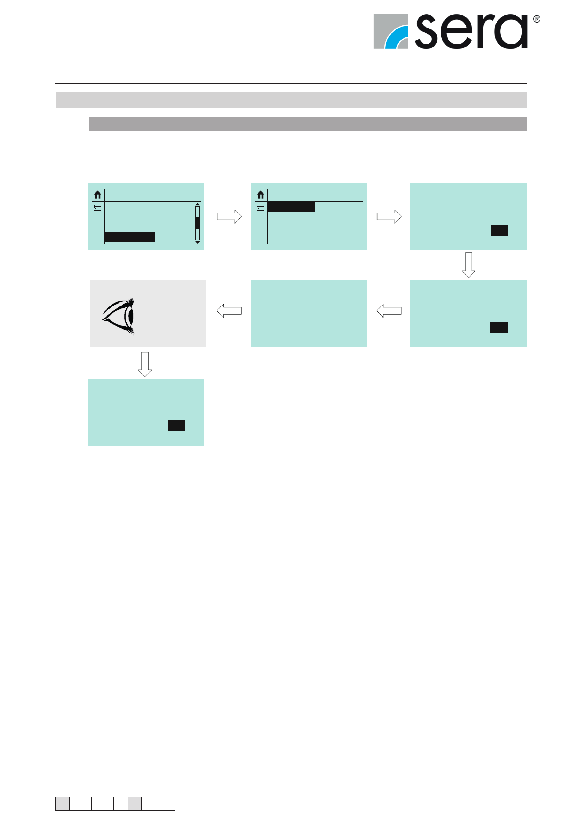
Stepper motor pump
®
iSTEP
Operating Instructions
10.10.6 Maintenance
CHANGE DIAPHRAGM
The diaphragm must be replaced if the Service message occurs.
The menu species the following procedure for the pump:
SYSTEM
Time
Password
Maintenancer
Chapter
SYSTEM
Change dia.
Service
Wartung
Disconnect power
Change
diaphragm ?
No Yes
Pump rinsed ?
and change
11.1.2
diaphragm!
No Yes
Diaphragm change
finished?
No Yes
The counters for diaphragm operating hours and diaphragm service life are reset after successful diaphragm
replacement.
TA 508 Rev. 00 en 11/2015
Subject to technical modications!
www.sera-web.com
67
Page 68
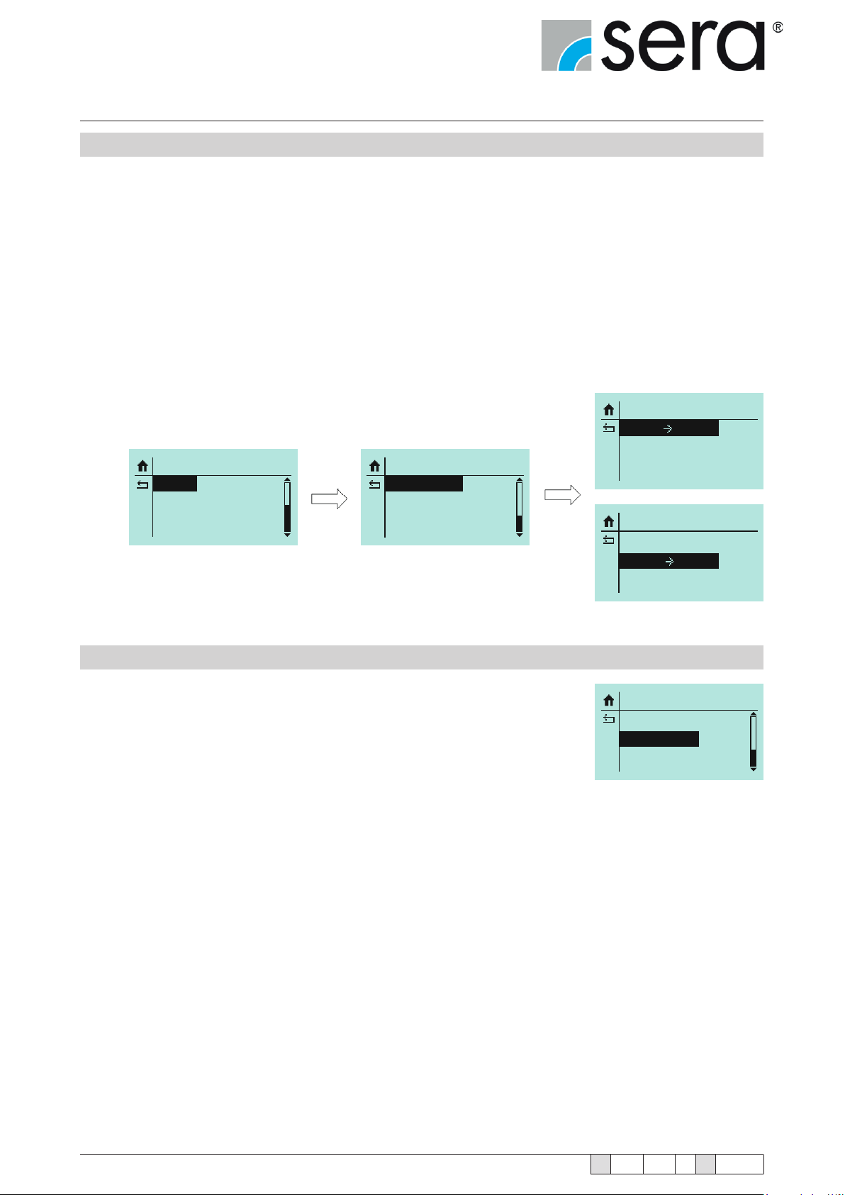
Stepper motor pump
®
iSTEP
Operating Instructions
10.10.7 Data transfer
Pump-Display
Data transfer from pump to the display
Display-Pump
Data transfer from display to the pump
For the data transfer, a pump must be parametrised to the required settings using the control panel.
Once this is done, the "Pump-Display" data transfer function transfers the parameter settings to the memory in
the display.
The display can now be unscrewed from the pump and connected to another pump. Using "Display-Pump" data
transfer, the parameters stored on the display can be transferred to the second pump. This process can be repeated any number of times with other pumps.
The advantage is that each pump does not have to parametrised individually.
EINSTELLUNGEN
System
Kalibrierung
Datentransfer
Pumpe Display
Display Pumpe
SYSTEM
Data Transfer
Factory Reset
Datentransfer
Pumpe Display
Display Pumpe
10.10.8 Factory settings
Restore pump to factory settings
(see parameters table for factory settings).
YES must be set and acknowledged for this.
SYSTEM
Data Transfer
Factory Reset
68
www.sera-web.com
Subject to technical modications!
TA 508 Rev. 00 en 11/2015
Page 69
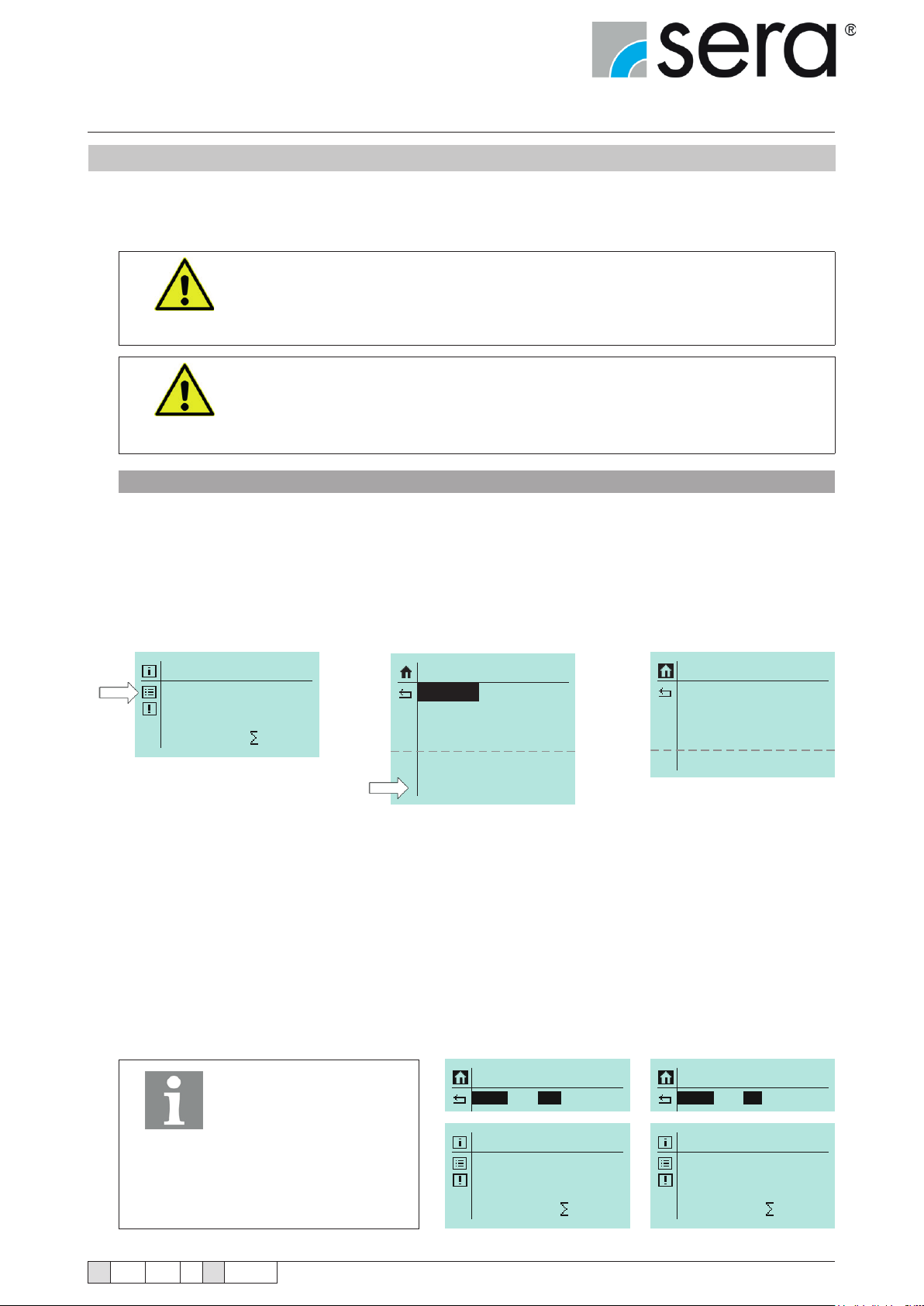
Stepper motor pump
®
iSTEP
Operating Instructions
10.11 Calibration of the delivery rate display
The calibration is used to activate the ow rate indicator.
Calibration is always done in the same way, no matter whether a ow meter is connected or not.
The correct sensor type must be set (see chapter 10.9.3 "Dosing monitor") before
the calibration with connected ow meter.
If no sensor type is set ("OFF"), the calibration will only activate the standard ow
ATTENTION!
rate indicator.
Pay attention to the safety data sheet of the pumped medium.
ATTENTION!
Sequence of calibration:
1) Route the suction line into a calibration pot lled with the dosing medium – the pressure line must be installed in
nal position, i.e. the pump is operating under operating conditions.
2) The dosing medium must be suctioned if the suction line is empty
(operating mode MANUAL, let pump run).
3) Note the ll level in the calibration pot (= base quantity).
4) Under SETTINGS select the CALIBRATION menu item.
MANUAL
100.0 % freq.
0 N
5) First, enter the required number of strokes (at least 200!).
► the higher the number of strokes, the more accurate is the calibration!
6) Enter frequency at which the pump should be operated later (10...100%).
7) Select Start calibration to start the calibration.
8) The dosing pump performs the specied number of strokes (wait for process).
SETTINGS
Parameter
In-/Outputs
Extras
System
Calibration
CALIBRATION
Active
Strokes
Frequency
Start Calibration
No
0200
080%
9) Determination of the delivered quantity
(= difference between base quantity and remaining quantity in the calibration pot).
10) Input of the determined delivered quantity (MEASURED VALUE).
CALIBRATION
Aktive
Yes
MANUAL
NOTE!
The value for the "Active"
parameter is automatically set to "Yes" after the
calibration has been
performed.
Q:20,000 l/h
This value can now be
changed!
TA 508 Rev. 00 en 11/2015
Subject to technical modications!
0 N
CALIBRATION
Aktive
MANUAL
100.0 % freq.
www.sera-web.com
No
0 N
69
Page 70

Stepper motor pump
®
iSTEP
Operating Instructions
Standard ow rate indicator
With the standard ow rate indicator, the entered target value is converted
to the corresponding stroke frequency.
Internal calculation:
100% stroke frequency > calibrated: 10 l/h
Setpoint: 8 l/h > 80% stroke frequency
Flow rate indicator with ow meter
The ow meter records the actual value, and the stepped motor pump readjusts the ow rate using the stroke frequency as soon as it deviates from the entered setpoint.
The maximum congurable setpoint is limited by the internally determined stroke length.
Example:
If a target value of 8 l/h is entered, the stroke frequency is accordingly rst reduced to 80%.
The ow meter measures a ow rate of 7.9 l/h. The internal regulation increases the stroke frequency
to 81% to reach 8 l/h.
The maximum setpoint in this case is 10 l/h.
Internal control:
100% stroke frequency > calibrated: 10 l/h 80% stroke frequency > actual value: 7.9 l/h
Setpoint 8 l/h > 80% stroke frequency 8 l/h > 81% stroke frequency
Effects on the indicators for the different operating modes
MANUAL operating mode
After calibration of the dosing pump, the delivery rate is entered directly as setpoint in l/h
instead of via the stroke frequency adjustment.
In the “Operating messages” view, the stroke frequency display is replaced accordingly with the ow rate display.
The total dosing volume is also still indicated in litres.
ANALOGUE operating mode
After calibration of the dosing pump, the delivery rate is entered directly as setpoint in l/h
instead of via the stroke frequency adjustment.
The calibration of the pump activates the ow rate indicator and the total dosing quantity in litres
is also shown.
BATCH operating mode
After calibration of the dosing pump, the delivery rate is entered directly as setpoint in l/h
instead of via the stroke frequency adjustment.
After calibration of the pump, the dosing volume and the remaining dosing volume are indicated in litres.
IMPULSE operating mode
After calibration of the dosing pump, the delivery rate is entered directly as setpoint in l/h
instead of via the stroke frequency adjustment.
After calibration of the pump, the total dosing volume is also indicated in litres.
TIMER operating mode
After calibration of the dosing pump, the delivery rate is entered directly as setpoint in l/h
instead of via the stroke frequency adjustment.
70
www.sera-web.com
Subject to technical modications!
TA 508 Rev. 00 en 11/2015
Page 71
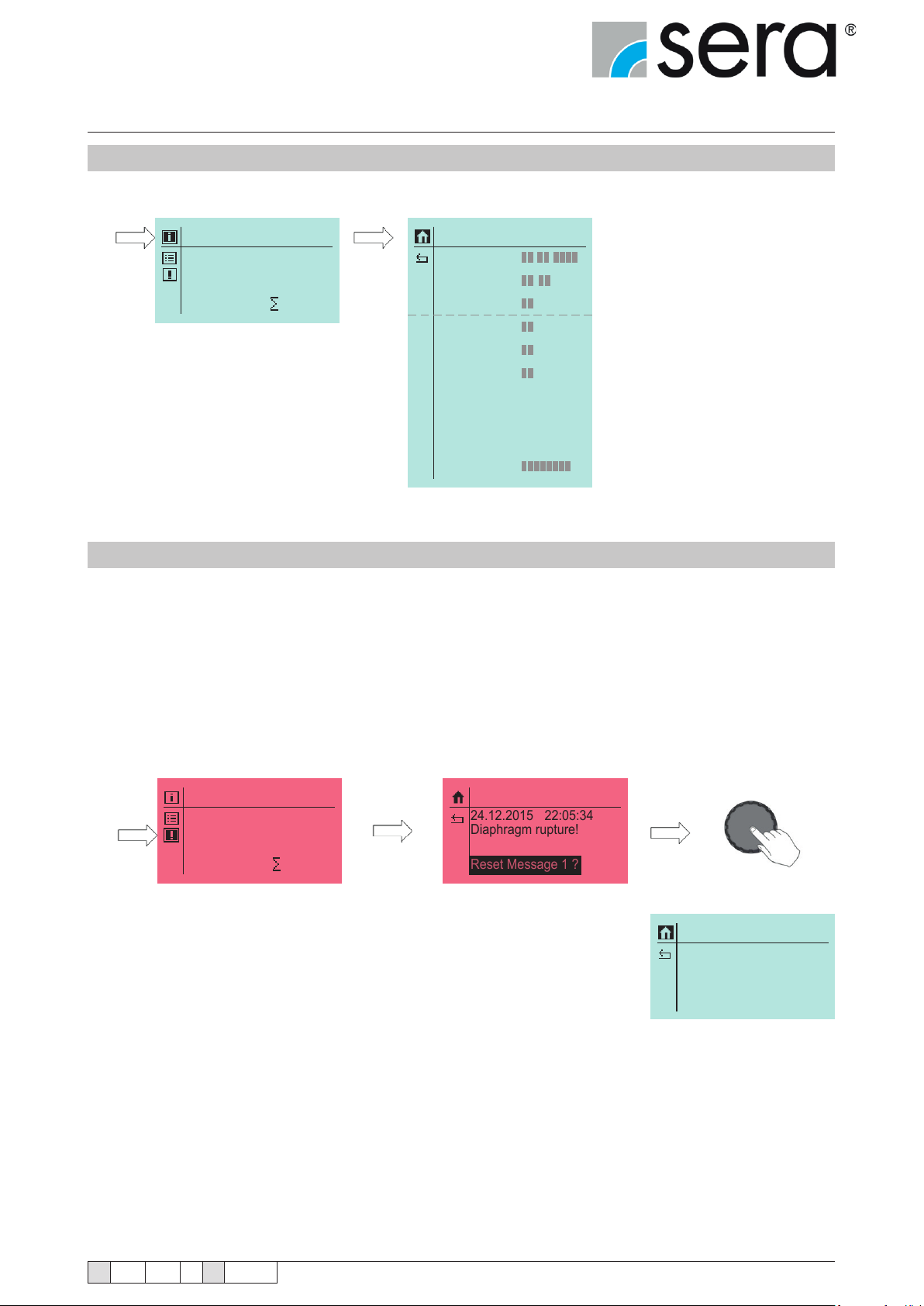
Stepper motor pump
Diaphragm rupture!
Reset Message 1 ?
22:05:34
24.12.2015
®
iSTEP
Operating Instructions
10.12 Info
The following information can be recalled:
MANUAL
100.0 % freq.
0 N
Info
Date
Time
Tot. Strokes
Dia. Hours
Tot. Quantity
Operat. Hours
SW-Version
HW-Version
sera Code
Serial-No.
xx.xx.xxxx
11:01
37N
37h
37L
37h
vCprot10
vHC02.001
19570
10.13 Messages
The messages menu function can be reached using a message icon from the operating mode window.
All messages that occur during operation are displayed here in plain text and with date and time of the occurrence.
The displayed messages are in chronological order.
Clicking on the text: Delete message x? deletes the message from the memory.
However, this is only possible if the signal is no longer present. For example, if the fault has not been rectied, it is not
possible to delete the error and it is written to the memory again.
"No messages available" is displayed if no messages are stored.
MANUAL
Messages
100.0 % freq.
0 N
Messages
Any message during operation is shown on the display immediately.
No Messages!
TA 508 Rev. 00 en 11/2015
Subject to technical modications!
www.sera-web.com
71
Page 72
Stepper motor pump
®
iSTEP
Operating Instructions
11. Maintenance
The following safety instructions are applicable for all maintenance work and must be strictly followed.
Take appropriate protective measures:
wear protective clothing, breathing protection and protective goggles. Prepare a
container with appropriate liquid in the immediate vicinity of the pump to be able to
remove splashes of the pumped medium.
DANGER!
All maintenance work must only be performed on depressurised systems that are
disconnected from the power supply.
WARNING!
WARNING!
WARNING!
WARNING!
DANGER!
Repairs on the stroke drive may only be performed by sera.
The pump should only be opened by sera or after previous consultation with sera.
Before starting all maintenance work, ensure that the required wear and/or spare
parts are available.
Place / deposit system parts so that any damage is prevented.
All wear parts must be checked at regular intervals for faultless
condition and replaced if necessary.
Pay attention to the cleanliness of sealing surfaces when replacing wear parts. Any
soiling can result in inadequate leak tightness!
Before maintenance work, empty the pump and, if necessary, rinse it with appropriate
liquid, and avoid contact with aggressive and/or toxic media!
Rinse dosing pump with suitable ushing agent so that no residues of the pumped
DANGER!
The following checks should be performed regularly:
■ the piping is tightly tted,
■ pressure and suction valve are tightly tted,
■ the electrical connections are in proper condition,
■ the pump body fastening bolts are tightly tted (check this at least quarterly).
For the tightening torques of the fastening bolts, see "Overview of the tightening torques" chapter.
72
medium remain in the pump body. Otherwise, pumped medium discharges when dismantling the pump. Collect the rinsed out liquid in a safe way (avoid contact with it)
and dispose of it in an environmentally compatible way. Observe the safety data sheet
for the pumped medium for this.
This measure is also necessary if the dosing pump should be returned for repair.
www.sera-web.com
Subject to technical modications!
TA 508 Rev. 00 en 11/2015
Page 73
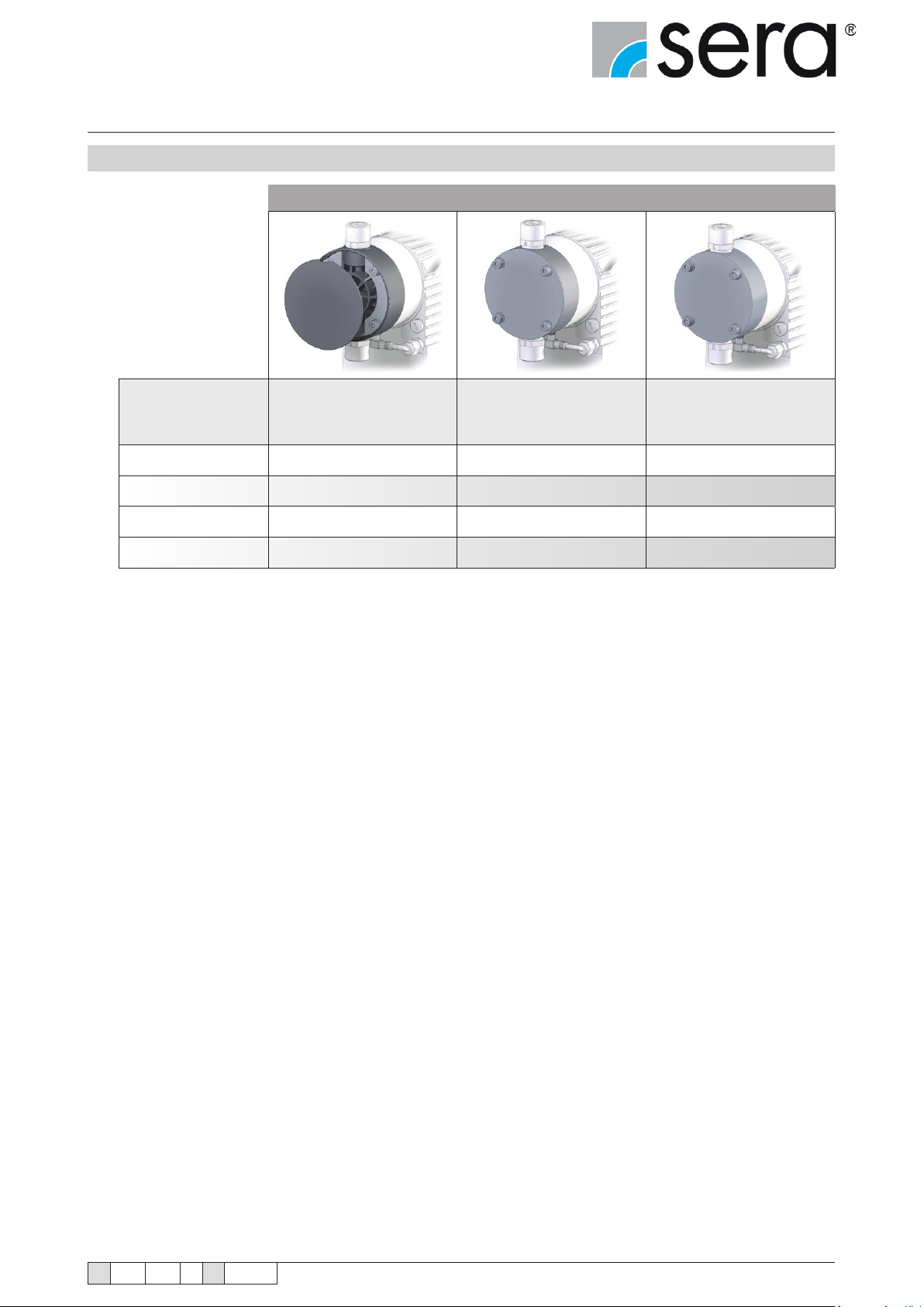
Stepper motor pump
®
iSTEP
Operating Instructions
11.1 Overview of the tightening torques
TIGHTENING TORQUES OF THE FIXING SCREWS
Pump body Pump body ...FRP Pump body PVC Pump body 1.4571
Nm Nm Nm
iSTEP
iSTEP
iSTEP
iSTEP
®
®
®
®
S 15
S 30
S 40
S 50
4 4,5 4
5 6 5
5 6 5
5 6 5
TA 508 Rev. 00 en 11/2015
Subject to technical modications!
www.sera-web.com
73
Page 74
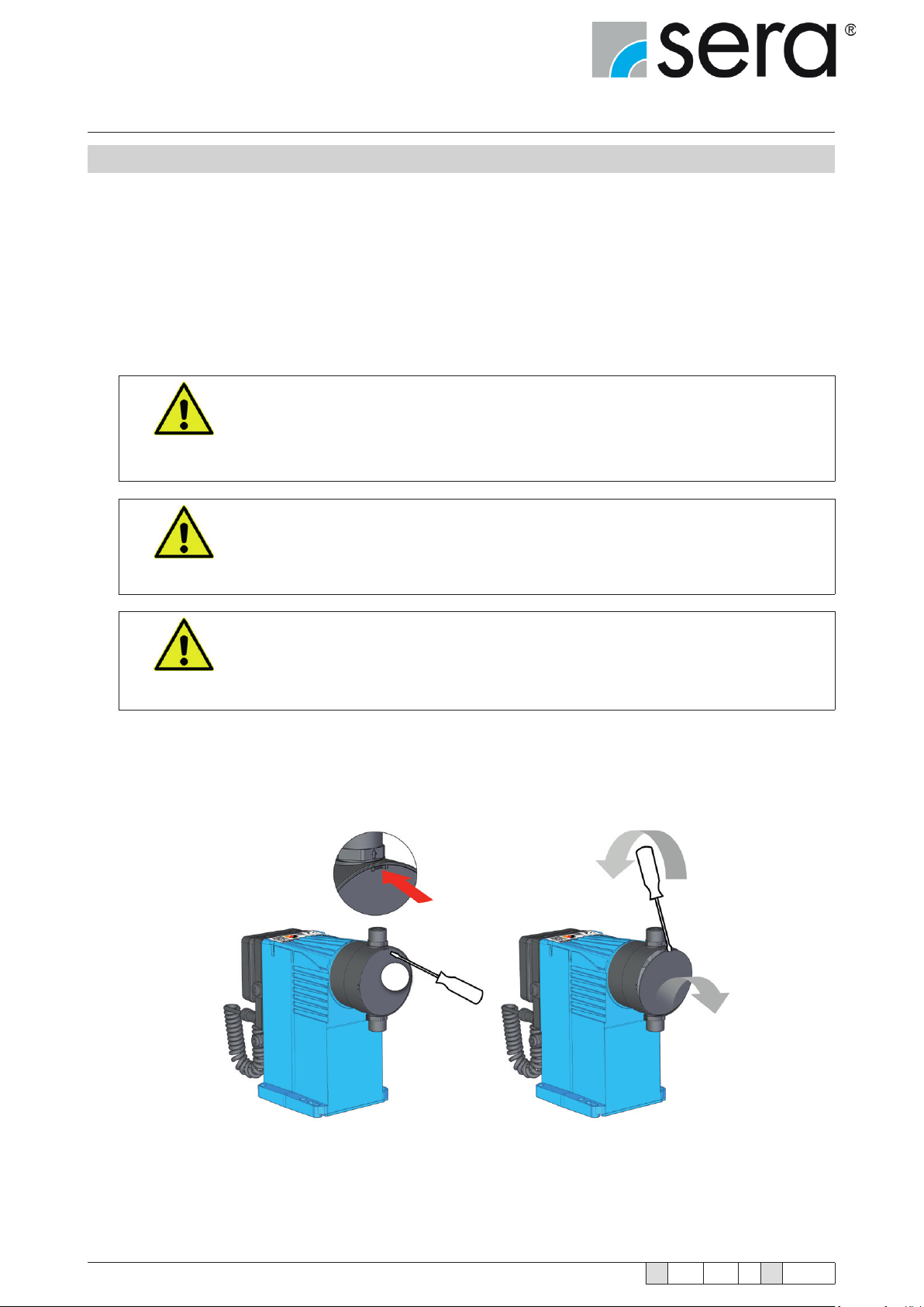
Stepper motor pump
®
iSTEP
Operating Instructions
11.2 Diaphragm replacement
For fault-free functioning of the dosing pump and for compliance with the required safety and protective characteristics, regular checking and replacement of the diaphragms are indispensable.
After 3000 operating hours or at the latest after one year, a service message requiring diaphragm replacement is
shown on the graphical display of the pump. An earlier diaphragm replacement can be necessary depending on the
medium and the application area.
The diaphragm replacement is performed using the diaphragm replacement mode of the electronics (see chapter
10.10.6 "Maintenance"). If this is performed in accordance with the instructions on the graphical display, the diaphragm is put into a suitable position for the replacement.
Strictly observe and follow the safety instructions in Chapter 11 "Maintenance".
Man, machine and environment are endangered if the safety instructions are not
WARNING!
observed.
Observe the instructions on the graphical display for the replacement of wear
parts.
WARNING!
Replacement of the wear parts must only be performed on depressurised systems
that are disconnected from the power supply.
WARNING!
■ Remove cover plate (1) of the pump body (GRP design).
1
74
www.sera-web.com
Subject to technical modications!
TA 508 Rev. 00 en 11/2015
Page 75
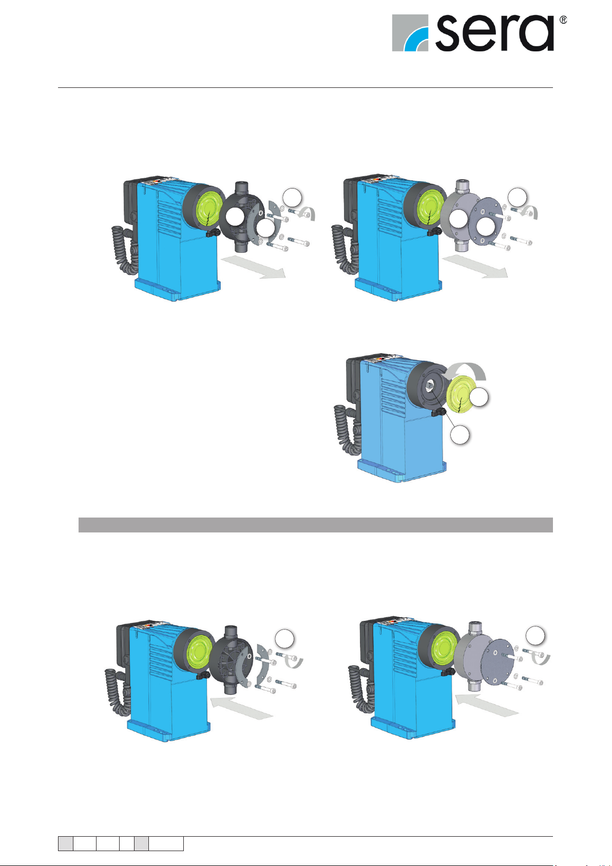
Stepper motor pump
®
iSTEP
Operating Instructions
■ Loosen xing bolts (2) on the pump body.
■ Remove pump body (3), front plate (4) (PVC design) or insertion plates (5) (GRP design) to the front.
2
3
5
■ Unscrew defective drive diaphragm (6) from the push
rod (7).
2
3
4
6
7
Assemble in reverse order
■ Screw on new diaphragm hand-tight.
■ Observe tightening torques of the xing bolts (2); see "Overview of the tightening torques" chapter.
■ When assembling the pump body, please note: suction valve below, pressure valve above!
2
Connect the suction and pressure lines as well as the electrical connection of the dosing pump.
The dosing pump is operational again after executing the instructions on the graphical display (see chapter 10.10.6
"Maintenance").
2
TA 508 Rev. 00 en 11/2015
Subject to technical modications!
www.sera-web.com
75
Page 76

Stepper motor pump
®
iSTEP
Operating Instructions
12. Spare and wear parts
12.1 Wear parts
The following parts are considered as wear parts of the dosing pump:
■ Drive diaphragm
■ Valve set
■ Diaphragm rupture electrode
Depending on their use and period of use, wear parts must be replaced at regular intervals in order to ensure reliable
functioning of the dosing pump.
sera recommends replacement of wear parts after 3000 operating hours or at least once per year.
In the event of premature diaphragm rupture caused by harsh operating conditions, switch off the dosing pump and
replace the drive diaphragm (in accordance with "Diaphragm replacement" chapter).
12.2 Spare parts
The following parts are considered as spare parts of the dosing pump:
■ Pump body kit
■ Base ring kit
■ Automatic ventilation device kit (option)
76
www.sera-web.com
Subject to technical modications!
TA 508 Rev. 00 en 11/2015
Page 77
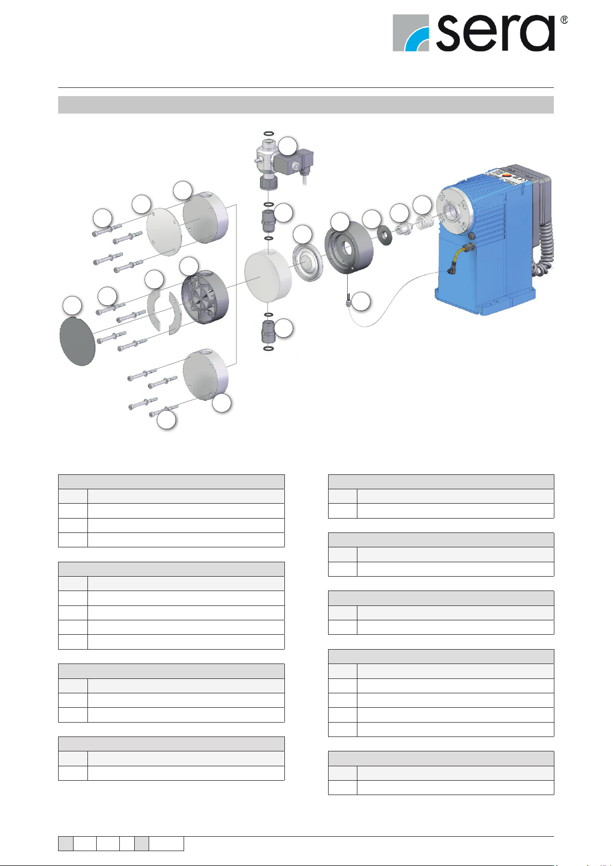
Stepper motor pump
®
iSTEP
Operating Instructions
12.3 Spare and wear parts kit
3
2
1
7
6
5
4
11
10
13
14
18
15
16
17
12
9
8
Pump body kit (PVC design) Pressure valve kit
Pos. consisting of Pos. consisting of
1
Bolts, complete
2
Front plate
3
Pump body Suction valve kit
Pump body kit (GRP design)
Pos. consisting of
4
Cover plate Diaphragm kit
5
Screws, complete Pos. consisting of
6
Insertion plates
7
Pump body
Pump body kit (1.4751 design) Pos. consisting of
Pos. consisting of
8
Screws, complete
9
Pump body
Automatic ventilation device kit (option)
Pos. consisting of MBE
10
Automatic ventilation device (incl. O-ring) Pos. consisting of
11
Pressure valve (incl. O-rings)
Pos. consisting of
12
Suction valve (incl. O-rings)
13
Drive diaphragm
Base ring kit
14
Base ring
15
Flat seal
16
Push rod adapter
17
Compression spring
18
Diaphragm rupture electrode
TA 508 Rev. 00 en 11/2015
Subject to technical modications!
www.sera-web.com
77
Page 78
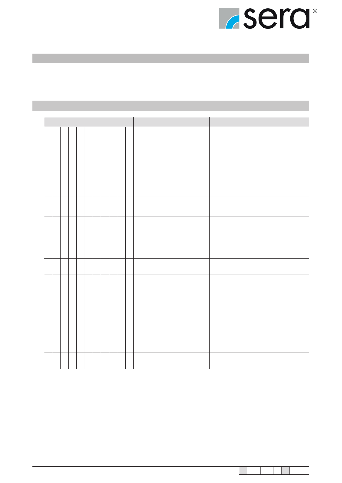
Stepper motor pump
®
iSTEP
Operating Instructions
13. Fault analysis and fault correction
sera products are sophisticated technical products which are only shipped after having been thoroughly tested and
checked at our factory.
Should there be any faults, these can be detected and rectied easily and quickly based on the error messages in the
display and the instructions in the tables.
13.1 Analysis of the plain text error messages
Error message Possible cause Corrective action
Time error!
No ow!
Flow rate too low!
Pulse memory full!
Analogue signal < 4 mA!
Analogue signal > 20 mA!
Analogue signal > 25 mA!
Mains voltage too low!
Mains voltage too high!
█ █ █ █
█
█ █
█
█
█ Pulse factor too high. Check process parameters.
█
Order wear parts kit.
No stroke detection!
Electrical data of the dosing
pump do not match mains data.
Broken wire in the analogue
signal line.
Type of the specied analogue
signal (e.g. 4-20 mA) does not
match the actual analogue signal
(e.g. 0-20 mA).
Analogue signal transmitter (sensor, regulator) has a fault.
Frequency of the incoming
pulses is (constantly) higher than
the maximum stroke frequency of
the dosing pump.
Diaphragm has exceeded the
█
maximum service life of one year
or the maximum operating hours.
Sensors of the dosing pump
defective.
Check order data. Check electrical installation.
Check the analogue signal line and repair if
necessary.
Check the specied analogue signal and
adjust to the actual analogue signal if necessary.
Check the analogue signal transmitter and
correct fault.
Check process parameters.
Contact sera and order diaphragm kit.
Contact sera.
78
www.sera-web.com
█
Defective battery for the power
supply of the real-time clock.
Subject to technical modications!
Contact sera.
TA 508 Rev. 00 en 11/2015
Page 79

Stepper motor pump
®
iSTEP
Operating Instructions
Error message Possible cause Corrective action
Dry running dosing pump!
Drive fault!
Diaphragm rupture!
No ow!
Flow rate too low!
Pre-alarm level!
█ █ █ Defective drive diaphragm. Replace drive diaphragm.
█ █ █ Suction height too high. Reduce suction height or suction resistance.
█ █ Suction pipe leaking. Check seals, tighten pipe connections.
█ █ █ Shut-off valves in piping closed.
█ █ █ █
█ █ Pump valves leaking. Remove and clean valves.
█ █
█ █
Motor overtemperature!
No stroke detection!
Medium level in storage tank too
low or no medium.
Pump valves (ball seats) damaged.
Pump valves incorrectly installed
or valve balls missing.
Open shut-off valves or check opening state – check
pump for possible damage.
Fill storage tank.
Remove and clean valves, check function; replace valves
if necessary.
Check installation position and completeness – replace
missing parts or install correctly
█ █ █ Filter in suction line clogged. Clean lter.
█ █ █ █ Backpressure too high.
█ █
█ █ █
█ █ █ █
█ █
█ █
█ █ █
█ █ Pipe connections leaking.
█ █ █ █ Pumped medium frozen in pipe.
Foreign matter in the pump
valves.
Acceleration height too high due
to pipe geometry.
Viscosity of the pumped medium
too high.
Pumped medium is outgassing
in the suction pipe and/or the
pump body.
Air in suction line while pressure
is present on the pressure side.
Reversible thermal fuse of the
pump has tripped.
Measure pressure with manometer directly above pressure valve if possible and compare with permissible
backpressure.
Remove and clean valves.
Check acceleration height on suction and pressure sides
with manometer and compare with design data – install a
pulsation damper if necessary.
Check viscosity of the pumped medium and compare with
design data – reduce concentration or increase temperature if necessary or install other pump valves.
Check geodetic conditions and compare with data of the
pumped medium. Operate pump with suction side supply,
reduce temperature of the pumped medium.
Vent pressure side or open vent valve.
Let temperature of the pump cool down. Check ambient
temperature.
Tighten connections according to type of material. Be
careful with plastic – risk of fracture!
Remove pump and check for possible damage - increase
temperature of the pumped medium.
█ █ Pump valves dry. Moisten pump body and valves. Open vent valve
TA 508 Rev. 00 en 11/2015
Subject to technical modications!
www.sera-web.com
79
Page 80
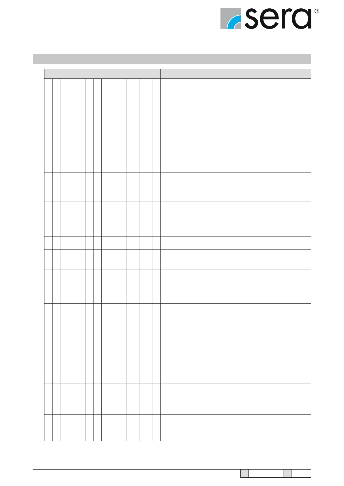
Stepper motor pump
®
iSTEP
Operating Instructions
13.2 Analysis of other faults
Fault type Possible cause Corrective action
Flow rate uctuates
Maximum permissible ow rate exceeded
Pipe oscillates heavily
Too high noise development
Service life of the drive diaphragm
too low
Drive is overloaded (periodically occurring
noises)
Pump does not run
Operation indicator (display, LED) not lit
Pump does not draw in
Pump does not deliver
Flow rate is not reached
Delivery head is not reached
█ █ █ Suction height too high.
█ █ █ █ Suction pipe leaking
█ █ █ █ █
█ █ █
Leakage on pump head
Shut-off valves in piping
closed.
No pumped medium in storage tank.
Reduce suction height or suction
resistance.
Check seals, tighten pipe connections.
Open shut-off valves or check
opening state – check pump for
possible damage
Fill storage tank.
█ █ █ █ █ Pump valves leaking. Remove and clean valves.
█ █ █ █
█ █
█ █ █ █ Filter in suction line clogged. Clean lter.
█ █ █ █ █
█ █ █ █ █ █ █ █ Backpressure too high
█ █ █ █ █
█ █
█ █ █ █ █ █ █ █
Pump valves (ball seats)
damaged.
Pump valves incorrectly
mounted or valve balls missing.
Electrical data of the pump do
not match mains data.
Foreign matter in the pump
valves.
Pressure on suction side
higher than at the end of the
pressure pipe.
Acceleration height too high
due to pipe geometry.
Remove and clean valves, check
function; replace valves if necessary
Check installation position and
completeness – replace missing
parts or install correctly
Check order data.
Check electrical installation.
Measure pressure with manometer
directly above pressure valve if
possible and compare with permissible backpressure.
Remove and clean valves.
Check geodetic conditions, install
oat valve or pressure-sustaining
valve if necessary.
Check acceleration height on suction and pressure sides with manometer and compare with design
data – install a pulsation damper if
necessary.
80
www.sera-web.com
█ █
Materials coming into contact
with the medium not suitable
for the pumped medium.
Subject to technical modications!
Check whether the pumped medium matches the design data and
select other materials if necessary.
TA 508 Rev. 00 en 11/2015
Page 81
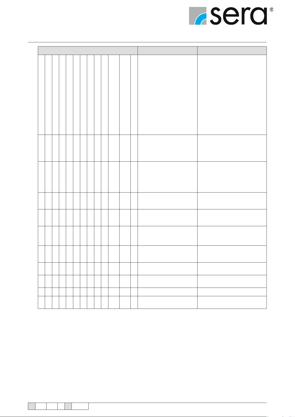
Stepper motor pump
®
iSTEP
Operating Instructions
Fault type Possible cause Corrective action
Flow rate uctuates
Maximum permissible ow rate exceeded
Pipe oscillates heavily
Too high noise development
Service life of the drive diaphragm
too low
Drive is overloaded (periodically occurring
noises)
Pump does not run
Operation indicator (display, LED) not lit
Pump does not draw in
Pump does not deliver
Flow rate is not reached
Delivery head is not reached
Leakage on pump head
█ █ █ █
█ █ █
█
█
█ █ █ █ █ Pipe connections leaking.
█ █
█ Fuse in electronics blown. Return pump for repair.
█
█ █ █ No mains power connection. Connect mains power supply.
█ Pump valves dry.
Viscosity of the pumped
medium too high.
Pumped medium is outgassing in the suction pipe and/or
the pump body.
Air in suction line while pressure is present on the pressure side.
Reversible thermal fuse of the
pump has tripped.
Pumped medium frozen in
pipe.
Power supply failed / switched
off.
Check viscosity of the pumped medium and compare with design data
– reduce concentration or increase
temperature if necessary.
Check geodetic conditions and
compare with data of the pumped
medium. Operate pump with suction side supply, reduce temperature of the pumped medium.
Vent pressure side.
Let temperature of the pump cool
down.
Check ambient temperature.
Tighten connections according to
type of material. Be careful with
plastic – risk of fracture!
Remove pump and check for possible damage - increase temperature
of the pumped medium.
Restore power supply.
Moisten pump body and valves.
Open vent valve
TA 508 Rev. 00 en 11/2015
Subject to technical modications!
www.sera-web.com
81
Page 82
Stepper motor pump
®
iSTEP
Operating Instructions
14. Shut-down
■ Switch off piston diaphragm pump.
■ Rinse pump head and remove pumped medium; make sure that the rinsing agent is suitable for pumped medium
and pump head.
Pay attention to the safety data sheet of the pumped medium.
ATTENTION!
Ensure absence of voltage of the pump. Danger from electricity!
DANGER!
15. Disposal
■ Shut-down system. Please see “Shut-down“.
15.1 Dismantling and transport
■ Shut-down system. Please see “Shut-down“.
■ Remove all uid residues from pump body, clean thoroughly, neutralize and decontaminate.
■ Package unit and ship.
A clearance certicate must be lled in when systems are returned to the manufacturer (see Chapter 16).
NOTE!
Acceptance will be rejected if this clearance certicate is not attached.
The consignor is responsible for leaking lubricants or
uids!
WARNING!
15.2 Complete disposal
■ Remove all uid residues from unit.
■ Drain off lubricants and dispose of according to regulations!
■ Dismount materials and send them to a suitable waste disposal company!
The consignor is responsible for leaking lubricants or uids!
WARNING!
82
www.sera-web.com
Subject to technical modications!
TA 508 Rev. 00 en 11/2015
Page 83
Stepper motor pump
®
iSTEP
Operating Instructions
16. Certicate of non-objection
Inspection / repair of machines and machine parts is only carried out after the op-
posite clearance certicate was lled in correctly and completely by authorized and
qualied personnel.
NOTE!
Acceptance will be refused if parts are returned to the manufacturer without a proper
clearance certicate.
NOTE!
All industrial companies are obligated by the legal provisions for occupational health, e.g. the workplaces ordinances,
the Ordinance on Hazardous Substances, the regulations for prevention of accidents and the environmental protection
regulations such as the Waste Management Act and the German Household Water Act to protect their employees or
man and the environment from detrimental effects when handling hazardous substances.
Should special safety precautions be necessary despite careful draining and cleaning of the product
the necessary information are to be provided.
Machines which are operated with radioactive media shall only be inspected and/or repaired in the
safety area of the owner by a sera specialized tter.
The clearance certicate is part of the inspection-/repair order.
sera reserves the right to refuse acceptance of the order for other reasons.
Please make a copy and leave the original with the operating instructions!
(can also be downloaded from: www.sera-web.com)
NOTE!
TA 508 Rev. 00 en 11/2015
Subject to technical modications!
www.sera-web.com
83
Page 84
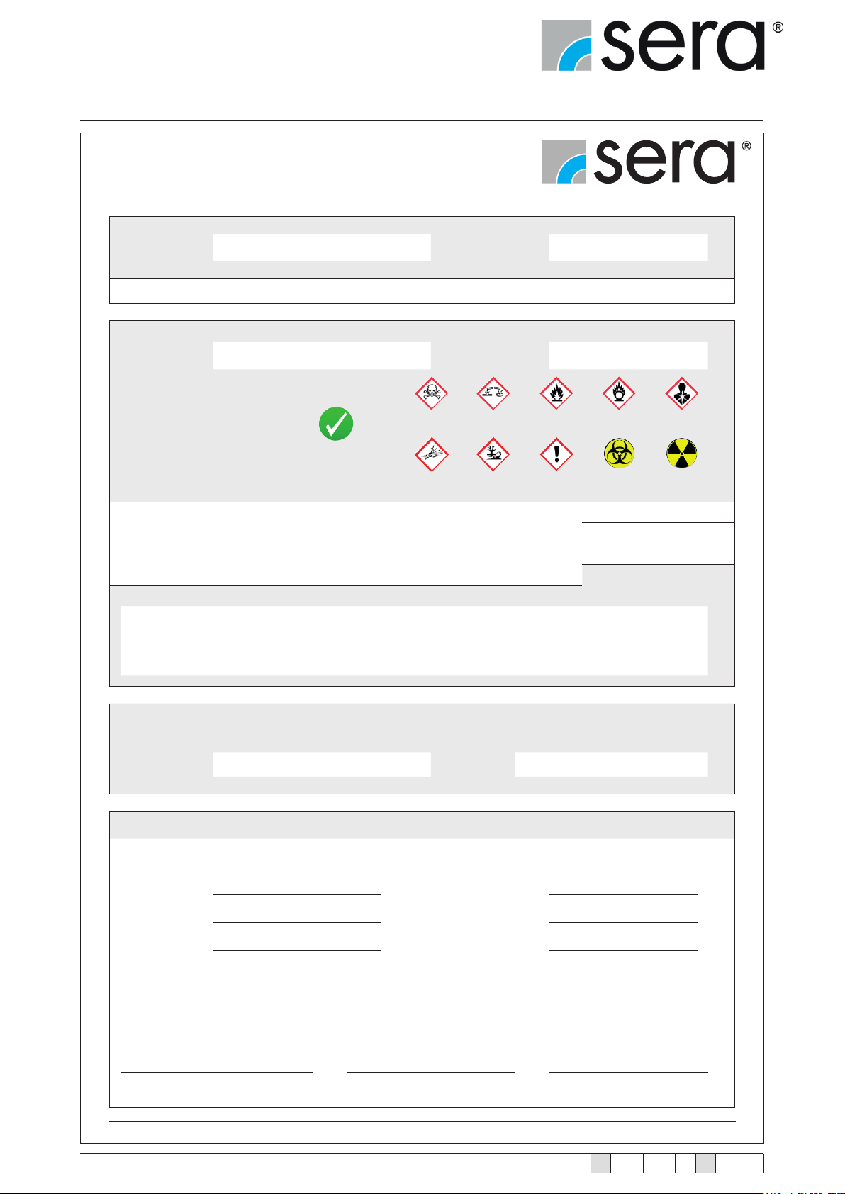
Stepper motor pump
®
iSTEP
Operating Instructions
Clearance Certicate
Product
Type Serial-No.
the product was carefully emptied before shipping / delivery, and cleaned inside and outside.
Conveying medium
Designation Concentration %
Properties
Please tick!
If either of the listed properties,
then enclose the appropriate
safety and handling instructions.
□
The product was used with health or water-polluting substances and came up with labeling
requirements and pollution prone media in contact.
Special security arrangements with respect to health or water-hazardous media
are in the further handling
The following safety precautions regarding rinsing, residual liquids and waste disposal are required:
□
Harmless
□
Toxic
□
Explosive
□
Corrosive□Flammable□Oxidising□Unhealthy
□
Dangerous for
the environment
□
Irritant
□
hazardous
□
□
□
□
□
Bio-
YES
NO
not required
required
□
Radioactive
YES
Process data
The product was used with the following operating conditions described conveying medium:
Temperature °C Pressure bar
Sender
Company: Telephone:
Contact person: FAX:
Address: E-mail:
Zip code, City: Your order No:
We conrm that we have the information in this safety certicate (Clearance Certicate) have been correctly and
completely and that the returned parts were carefully cleaned.
The parts are sent free of residues of dangerous amount.
Place, Date Department Signature
(and company stamp)
www.sera-web.com
QSF 469-01 en / 11.2014 / PM
1
84
www.sera-web.com
Subject to technical modications!
TA 508 Rev. 00 en 11/2015
Page 85

Stepper motor pump
®
iSTEP
Operating Instructions
NOTES
TA 508 Rev. 00 en 11/2015
Subject to technical modications!
www.sera-web.com
85
Page 86

 Loading...