


LISST-200X
Particle Size Analyzer
User’s Manual
Version 1.3B
(January 2018)
2700 Richards Road, Suite 107
Bellevue, WA 98005-4200
Tel: (425) 641-0944 Fax: (425) 643-0595
Store Software
USB Card Here


LISST-200X User’s Manual Page iii
This document is copyrighted by SEQUOIA SCIENTFIC, INC


LISST-200X User’s Manual Page v
Welcome to the LISST-200X Particle Size Analyzer
Using this manual
This manual is divided into two sections.
I. LISST-200X contains an introduction to the LISST-200X
instrument and the principles of its operation.
II. LISST-200X Operation provides a detailed set of instructions
for using and caring for the instrument.
Technical assistance
For technical assistance please contact your local Distributor or
Sequoia. Please be sure to include the instrument serial
number with any correspondence.
IMPORTANT: Please read APPENDIX H:
TECHNICAL ASSISTANCE BEFORE you call or
email.
Sequoia Scientific, Inc. contact information:
Telephone: +1(425) 641-0944
Email: info@sequoiasci.com
PLEASE NOTE: The LISST-100X particle size
analyzer will not communicate with the SOP200X
software described in this manual. If you have a
LISST-100X you can use SOPv5.1 to communicate
with and process LISST-100X data.


LISST-200X User’s Manual Table of Contents Page vii
Table of Contents
I. LISST-200X INTRODUCTION AND TUTORIAL .................................................................... 1
A. LASER DIFFRACTION AND THE LISST-200X ............................................................................ 1
B. LISST-200X GENERAL DESCRIPTION .................................................................................... 4
C. LISST-200X QUICK START TUTORIAL .................................................................................... 7
II. LISST-200X OPERATION DETAILS .................................................................................... 31
D. STEP BY STEP PROCEDURES ............................................................................................... 32
1. Installing LISST-SOP Software..................................................................................... 32
2. Establishing Communication with the LISST-200X ...................................................... 33
3. Saving and Evaluating Clean Water Backgrounds ....................................................... 35
4. Configuring Data Collection .......................................................................................... 38
5. Using the Small External Battery Pack ......................................................................... 44
6. Using the Large External Battery Pack ......................................................................... 47
7. Offloading and Deleting Data Files from Internal Memory ........................................... 51
8. Processing a Single Raw Data File .............................................................................. 52
9. Batch Processing Multiple Raw Data Files ................................................................... 57
10. View Processed Data File ........................................................................................ 61
11. Data Quality Control ................................................................................................. 64
12. Simple Real-Time Data Processing ......................................................................... 66
13. Collecting Data from an External Analog Sensor ..................................................... 69
14. Configuring the LISST-200X as a Sensor for a CTD ............................................... 70
E. INSTRUMENT COMMUNICATION ............................................................................................. 71
F. LISST-200X COMMAND SUMMARY ...................................................................................... 75
G. LISST-200X COMMAND DETAILS ......................................................................................... 77
1. Display Commands ....................................................................................................... 77
2. Setup Commands ......................................................................................................... 81
3. Acquisition/Action commands ....................................................................................... 88
H. PERFORMANCE OPTIMIZATION ............................................................................................. 91
I. INSTRUMENT MOUNTING, DEPLOYMENT ORIENTATION, STORAGE AND MAINTENANCE ............. 94
APPENDIX A: TECHNICAL SPECIFICATIONS ........................................................................... 98
APPENDIX B: PARTICLE SIZE BINS ........................................................................................ 100
APPENDIX C: DATA FILE FORMATS ....................................................................................... 101
APPENDIX D: PROCESSING DATA FILES USING MATLAB .................................................. 104
APPENDIX E: CONNECTOR PINOUTS FOR LISST-200X ....................................................... 106
APPENDIX F: LISST-SOP SOFTWARE BUTTON DESCRIPTION ........................................... 110
APPENDIX G: SPHERICAL AND RANDOM PARTICLE SHAPE MODELS ............................. 112
APPENDIX H: TECHNICAL ASSISTANCE & TROUBLESHOOTING ..................................... 113
WARRANTY ................................................................................................................................ 115
REVISION HISTORY ................................................................................................................... 118

LISST-200X User’s Manual Table of Contents Page viii

LISST-200X User’s Manual LISST-200X Introduction and Tutorial Page 1
I. LISST-200X Introduction and Tutorial
A. Laser Diffraction and the LISST-200X
Measurement
Principle and
Optics
Particle sizing by laser diffraction is currently the most widely prevalent
method in research and industry. It is a multi-parameter measurement.
Just as a set of 3 equations can be solved for 3 unknowns, a
measurement of light scattering at multiple angles can be solved for
equally as many concentrations in different sizes. For example, the
LISST-200X measures scattering into 36 angles; consequently, one
obtains concentrations in 36 size classes of particles. This is called the
particle size distribution (PSD). That is the essence of this method. In
order that you appreciate the importance of some steps in operation of
the LISST-200X, we recommend reading the rest of this chapter.
The measurement of scattering at multiple angles is done with a
collimated beam illuminating particles in water. Laser light scattering at
an angle from the beam arrives, through a daylight rejection filter, at the
focal plane of a receive lens at the same angle from lens axis (see
figure). Thus, distance from lens axis in the lens focal plane
corresponds to scattering angle. The photodetectors in the LISST
series instruments are a series of silicon rings spanning 60-degree
arcs. Each ring covers a small range of scattering angles. Rings are
used to achieve stability of inversion – conversion of set of multi-angle
scattering measurements to the PSD.
Notice that the laser beam itself is focused by the receive lens and
passes through a small aperture in the ring detector, centered on the
rings. This beam is sensed by a photodiode placed behind the ring
detector. This is the transmission sensor. As light is removed from the
laser beam by scattering, the beam is attenuated, i.e. the light
transmitted through water is reduced in intensity. A similar attenuation
also affects the light that is scattered by particles and sensed by ring
detectors. Thus, the transmission sensor provides a vital measurement
to de-attenuate the measured scattered light.

LISST-200X User’s Manual LISST-200X Introduction and Tutorial Page 2
Clean Water
Backgrounds
and Background
QC
Imperfections, such as micro-scratches on glass windows and lenses,
also scatter laser light. This is measured and stored; it constitutes a
Background (formerly termed zscat, as in scattering by zero
concentration of scatterers). This background is subtracted from the
total signal seen by ring detectors. It is also helpful in determining if the
instrument is properly aligned, and if all optics are clean and
unscratched. A factory background acts as a reference to compare
with, to identify degradation in laser output or fouling of optical
surfaces. The LISST-200X stores its factory background data in its
memory, as well as the user’s acquired background data.
The LISST-200X incorporates a major advance over our previous
LISST-100X. This is the automatic quality control of the background
data (QC). During background acquisition, after grabbing a group of
scans of all detectors, their means and variances are computed.
Comparing with the on-board factory background, these are used to
alert the user of possibilities such as laser degradation, possible optics
misalignment, contamination of data by thermal microstructure in the
water used for background, bubbles or particles in the supposedly
clean water, scratches on windows etc. If no warnings are generated,
the background passes QC and the user has the option to save it, or
repeat.
Ambient Light
Rejection
The laser diffraction method requires that the light arriving on the
detector be due entirely to scattering of light that originates with the
laser beam. Light from ambient sunlight can distort the results. The
LISST physically shields the detector from much ambient light, but not
all, so daylight at shallow depths can still be significant.
The LISST-200X now can measure the ambient light independently of
scattered light, and subtract it to completely remove its effects. (Note
that this function requires firmware version 1.4 or later, introduced in
May, 2017). See section H for more about ambient light rejection
(ALR).
Quick Estimates
of Particle
Concentration
and Mean Size
The process of inverting laser diffraction data to produce PSD requires
too much computation to execute in real time within the instrument. But
the LISST-200X does provide real-time estimates of the total particle
volume concentration and mean particle size. These are approximate
quantities, not as accurate as the fully-processed PSD, but are useful
for quick characterization of water conditions. For example, if used in
conjunction with a CTD package in profiling applications, the CTD
software could display the concentration and mean size as a depth
profile, revealing any vertical structure in the particle distribution. (Note
that real-time interface to a CTD requires proper configuration of the
LISST-200X’s auxiliary connector; see “Configuring the LISST-200X as
a Sensor for a CTD” on page 70.)

LISST-200X User’s Manual LISST-200X Introduction and Tutorial Page 3
The quick estimates are based on weighted sum of the net scattered
light. One set of weight factors yields the total volume concentration;
the other yields the area concentration of particles. The volume/area
ratio provides mean diameter, also known as the Sauter Mean
Diameter (SMD). Notably, SMD can be quite different from D50 in broad
or multi-modal size distribution situations. The SMD output is set to
zero in very clear waters, i.e. when transmission is above 98%. In such
clear waters, the SMD can become erratic. [For an explanation of this
method of SMD derivation, see: Shaped Focal Plane Detectors for
Particle Concentration and Mean Size Observations; Agrawal, Y.C. and
O.A. Mikkelsen, (2009), Optics Express, v 17, n 25, pp 23066-23077].
Particle Shape
Models –
Spheres or
Irregular Shape
The multi-angle scattering can be interpreted via inversion as arising
from spherical particles, or from irregularly shaped particles. Provided
software gives you the choice and the resulting PSD files are named
differently to distinguish them. As to which particle model to use, we
suggest that when working with natural waters, use the irregularly
shaped model. Only in exceptional circumstances, the spherical model
is appropriate.

LISST-200X User’s Manual LISST-200X Introduction and Tutorial Page 4
B. LISST-200X General Description
Instrument
Description
The LISST-200X is capable of autonomous operation when used with
external battery packs. Windows software (compatible with Windows
XP through Windows 10) is provided to program the instrument for a
specific sampling schedule. The primary measurements delivered by
the LISST-200X are the small-angle scattering properties of particles in
water, the laser optical transmission, depth, and temperature. An
Auxiliary port is available for that can be configured for recording data
from an external device such as a turbidity or fluorometer or output
summary data (mean size and total concentration) as analog voltages.
For details of the possible configurations of the Auxiliary Port, see
Appendix E: Connector Pinouts for LISST-200X on page 106.
After recovery of the instrument, small-angle scattering data are offloaded from the instrument and subsequently inverted mathematically
on a computer to produce the particle size distribution. The inversion
function is included in the Windows software. For MATLAB users,
inversion scripts are available for download from Sequoia’s website:
www.SequoiaSci.com.
The LISST-200X instrument is a laser diffraction device. It consists of
optics for producing a collimated laser beam, a specially constructed
detector array, electronics for signal pre-amplification and processing,
data storage and scheduling computer, and an external battery system.
The principal measurement—angular scattering distribution— is
obtained over 36 ring-detectors whose radii increase logarithmically
from 102 to 20,000 microns. The detector is placed in the focal plane of
the receiving lens. The rings cover an angular range from 0.00085 to
0.34 radians. This angular range corresponds to size ranges from 1.00
to 500 µm. See Appendix B: Particle Size Bins on page 100 for more
information.
The LISST-200X consists of the following parts: a solid-state diode
laser operating at 670 nm wavelength and fiber-optically connected to a
laser beam collimating system, a beam manipulation and orienting
system, a two pressure windows, a scattered-light receiving lens, the
custom designed 36-ring detector, preamplifier electronics, a ringselecting multiplexer circuitry, and a data logger. All these components
are inside the black-anodized pressure housing.
The LISST-200X does not have internal batteries and therefore
should not need to be opened.

LISST-200X User’s Manual LISST-200X Introduction and Tutorial Page 5
Data Storage
and Interface
The LISST-200X includes high-capacity data logging and storage. The
logging functions are programmed via the provided software. It can be
programmed with different start and stop conditions as well as different
sampling rates and average durations. The data logger stores the data
in non-volatile Compact Flash memory which can be later downloaded
and processed into size distributions and concentration using the
provided software.
The data logger will also accept commands via the RS232 interfaces.
These commands can be used to program the instrument or to
exchange data with another instrument.
Depth and
Temperature
In addition to measuring the particle size and concentration, the LISST200X also has depth and temperature sensors. The depth sensor has
a 1000 psi full-scale range1. The stainless steel fitting on the
Connector endcap is used for testing this sensor, and keeps
contamination such as salt and sediment out of the pressure sensor.
The temperature is measured using a high precision thermistor
imbedded into a stainless steel probe on the Connector end cap. Both
values are stored automatically in the LISST-200X data file.
External I/O Port
The LISST-200X is also equipped with an external Auxiliary port which
is available via a 6-pin connector in the endcap. This port can be
configured in different ways by the user.
The Standard Configuration has one analog input and two digital
inputs. The analog voltage on this input is recorded with the size
distribution data. The digital inputs can be used to start and stop the
instrument.
The Analog Input Configuration has two analog inputs and switched
power which can be used to power the external sensor. Both analog
voltages are stored with every size distribution.
The Analog Output Configuration allows the Mean Size and Total
Concentration information to be output as analog voltages. The 6-pin
connector is wired to match the SeaBird CTD Auxiliary Input. This
allow the LISST-200X to obtain power from the CTD and output the
mean size and total concentration in real time to the CTD while the
detailed size distribution data is stored internally for later downloading.
The Auxiliary port can be reconfigured by the user by moving
mechanical jumpers on the main circuit board inside the instrument.
Contact Sequoia Scientific for instructions on how to access the jumper
on the circuit board.
1
A gauge pressure sensor is calibrated to measure the pressure relative to a given atmospheric pressure, as opposed to
an absolute pressure sensor, which measures pressure relative to a vacuum. The pressure sensor on the LISST-200X
will read 0 at atmospheric pressure.

LISST-200X User’s Manual LISST-200X Introduction and Tutorial Page 6
Battery Life
The LISST-200X does not contain internal batteries (except a small
battery to maintain the real-time clock), but can be powered from
multiple sources including a USB computer cable, Small or Large
Battery Packs (provided with the instrument) or an external instrument
such as a CTD.
The standard Small Battery Pack supplied with the LISST-200X uses
two NiMH rechargeable D-cell batteries and will provide about 12 hours
of continuous sampling.
The Large Battery Pack contains 16 standard alkaline D-cells. For
profiling applications, where the instrument is sampling continuously,
the Large Battery Pack has about 200 hours of sampling time or 200
days of stand-by. Powering down the instrument between samples can
greatly extend the deployment times. An Excel spreadsheet that can
estimate the battery consumption is included with the software on the
Ship Disk you received with your instrument. The spreadsheet can also
be downloaded from www.sequoiasci.com/product/lisst-200x, click
Library, then Downloads, then LISST-200X.
For laboratory or tethered usage, power can be supplied through the
communications connector on the endcap. A 2-meter USB cable is
provided that will power the instrument from the computers USB port.
No additional power is required to operate the instrument.
Cables up to 50 meters can be provided to supply external power and
communication with the instrument. This can allow real-time
observation of the size distributions.
Included
Accessories
The instrument is shipped pre-aligned and tested. A small chamber is
provided for obtaining measurements of background scattered light
from optical surfaces. This background is subtracted from actual
particle scattering measurements to obtain the true particulate
scattering. Additionally, small tools used to open endcaps, spare
batteries, and communication cable is supplied so that a user need only
provide a PC running Windows.
For extended laboratory applications various chambers are available
from Sequoia.
Software is provided to communicate with the instrument, schedule an
experiment, offload the data, and invert the measurements to obtain
particle size distribution and volume concentration. For laboratory use
or for monitoring the progress of an experiment, the software can be
used for real-time processing.

LISST-200X User’s Manual LISST-200X Introduction and Tutorial Page 7
C. LISST-200X Quick Start Tutorial
This section gives step by step instructions to unpack your LISST200X, load software, and acquire data in the lab. For more detailed
instructions on specific steps, background on how the instrument
works, or specific technical information such as cable pinouts please
refer to the full User’s manual following this Quick Start Tutorial.
Contents of
Shipping Case
Let’s assume that you are opening the LISST-200X shipping case for
the first time. Inside you will find the following:
• User’s Manual,
• USB memory card (credit card size) with the software,
• LISST-200X instrument,
• Plastic Instrument stands,
• Small Volume Test Chamber,
• USB Communications cable,
• Insulated stainless steel clamps,
• Small Battery Pack (without batteries),
• Larger Battery Pack with alkaline batteries installed,
• LISST-200X-to-Battery Pack cable,
• NiMH batteries and charger.

LISST-200X User’s Manual LISST-200X Introduction and Tutorial Page 8
Step 1: Remove
Instrument from
Shipping Case.
Start by removing the white plastic instrument stands and set them on
a flat working surface. Remove the LISST-200X from the case and set
it on the stands. The LISST-200X has two distinct ends that we will
refer to as the Optics endcap and the Connector endcap.
Optics Endcap
The optics endcap contains the optical windows that the laser beam
passes through to make a measurement. The internal optics and laser
electronics are mounted to the inside of this endcap.
Connector
Endcap
The connector endcap has three underwater connectors that are used
for communication, external power, and connecting to optional
accessories or instruments:
3-pin connector: Used for BioBlock, an anti-biofouling accessory
5-pin connector: Used for serial communication and external power.
6-pin connector: Used for analog in/out and digital in/out signals.
See Appendix E for a full description of the wiring of the underwater
connectors and mating cables.

LISST-200X User’s Manual LISST-200X Introduction and Tutorial Page 9
A temperature sensor is located between the 3-pin and 6-pin
connectors. In the center of the endcap is an LED that blinks when the
instrument is sampling. The stainless steel fitting with small tube is the
port for the depth sensor. This fitting can be removed to allow the port
to be cleaned should sediment or salt deposit build up.
Also on the Connector endcap is a white plastic lever. This
mechanical lever has a strong magnet embedded in the plastic. This
magnet can be used to trigger a digital switch inside the instrument
which can be programmed to start and stop the LISST-200X sampling.
The final item on the endcap is the zinc anode. The sacrificial zinc
anode protects the instrument from corrosion during long periods of
time in salt water.
Step 2: Check
for Clean
Windows
At this time, check the optical windows to make sure that they are
clean. There are two windows: The receive window (or large window)
and the transmit window (or small window). Both window need to be
very clean in order to get good measurements.
The best way to check the windows is by using a flashlight. By shining
light from one side and viewing from the other the surface of the
windows can be easily checked for cleanliness.

LISST-200X User’s Manual LISST-200X Introduction and Tutorial Page 10
If there is dirt or fingerprints on the windows clean them first by rinsing
them with lukewarm water and a mild soap solution (e.g. mild hand
soap, liquid dish soap) and then rinsing off all soap residue with clean,
particle free water such as deionized water, distilled water or bottled
drinking water. The windows can also be wiped clean with a soft cloth
(e.g. a lens cloth) or glass cleaner. It is not recommended to use
stronger solvents, such as acetone or toluene. Also, do not use any
abrasive cleaners or wipes. Treat the windows as you would an
expensive camera lens.
Step 3: Attach
Communication
and Power Cable
Remove the Communications cable from the plastic accessory case
within the shipping case. It is the 3 meter cable with the USB
connector on one end and the 5-pin underwater connector on the
other. Remove the underwater cap from the Communications
connector. The connectors will all look similar when the protective cap
is installed. The Communication connector is the only 5-pin connector
and is located next to the stainless steel pressure sensor fitting. After
removing the cap install the cable making sure that proper alignment
of the cable is maintained, so that the connector pins are not bent.
Plug the USB cable into the computer. Please note that USB drivers
may automatically install the first time the USB cable is plugged into
the computer. If the driver installed correctly, you should see the
green light on the USB cable blinking. For more information on
establishing and troubleshooting communication with the LISST-200X
see the Step-by-Step guide on page 32 of the User’s Manual.
Step 4: Install
the Horizontal
test chamber
Remove the Small Volume Horizontal test chamber from the
Accessory Case if it is not already installed on to the instrument. This
one-piece chamber is designed to slip between the optical windows of
the instrument such that the space between the windows can be filled
with water for testing or calibration.

LISST-200X User’s Manual LISST-200X Introduction and Tutorial Page 11
We can now fill the chamber with clean, particle-free water. Sequoia
uses steam-distilled bottled water filtered through a 0.2 micron filter.
Tap water may contain too many particles and may also contain
dissolved gas that can release and form small bubbles on the optical
surfaces. Pressurized filtered water can also contain dissolved gas.
Often the best source of clean water is bottled drinking water.
Step 5: Install
LISST-SOP200X
Software
At this point the instrument is ready to go. We now need to install the
software that is required for operation of the instrument. A USB
memory card the size of a credit card is included with each instrument.
In addition to the communication and processing program the disk also
contains digital copies of this manual and other support files. Insert the
memory card into a USB port on your PC to install the software. You
must install the software on a computer running Windows XP or later
(it is not compatible with Mac or Linux operating systems).
On the memory card you will find the ‘LISST-SOP200X_Installer.exe.’
The name LISST-SOP refers to the Standard Operating Procedure
functionality of the program. Double click the installer executable to
begin installing the software. Follow the onscreen instructions and the
installer will transfer the necessary files to your computer and place a
shortcut on your desktop and start menu. Do not remove the memory
card from your computer until the installation is fully completed.
Please note the following with respect to the LISST-SOP200X:
• On a 64-bit Windows PC, the software will be installed in the
following folder: C:\Program Files (x86)\Sequoia\LISST200X,
while on 32-bit Windows machines, the install folder will be
C:\Program Files\Sequoia\LISST200X
• The LISST-SOP200X WILL NOT work with the older LISST-100
or LISST-100X instruments. It is NOT possible to use the
program to offload data from a LISST-100 or LISST-100X
instrument, only a LISST-200X will work with this software.

LISST-200X User’s Manual LISST-200X Introduction and Tutorial Page 12
Step 6: Start
LISST-SOP200X
Application
Start the LISST-SOP software by selecting the shortcut the installer
placed on your desktop. See Appendix F: LISST-SOP Software Button
Description on page 110 of the User’s Guide for a brief description of
the toolbar buttons.
Step 7:
Establish
Communication
with the LISST200X
The LISST-200X does not have an internal battery. Power is supplied
to the instrument via a battery pack or USB cable. Please note that
the LISST-200X USB cable has a USB-to-serial convertor and special
power supply that converts the +5V to +11V to run the instrument built
into cable. When using this cable no other power source is required.
Power can also be provided by the Small and Large External Battery
Packs or another external power source such as a CTD. When using
an external battery the serial communication passes through the
battery pack. However, the power from the USB is not used power the
instrument. Power will be drawn from the battery only.
When connecting to your instrument from the software, the first step is
to open a communication port with instrument. From the
Communication menu select Serial Port Settings. You will see the
window below:
Select the port your LISST-200X is connected to from the drop down
menu of next to ‘Serial Port.’ The other two fields can be left at their
default values. Press the ‘OK’ button to save the changes.
Next, open the port by selecting Connect from the Communication
menu or pressing the button. After connecting, may need to wake
your instrument from sleep before continuing. To wake up the
instrument select Wake Up LISST from the LISST menu or press the
button. A dialog box will appear counting down the maximum time
required for the instrument to wake up. Upon wake up the instrument
status will be displayed. If the cable connections are not correct or if

LISST-200X User’s Manual LISST-200X Introduction and Tutorial Page 13
the power is not getting to the instrument a warning message will
appear after the time expires. The serial port settings can be checked
by selecting Serial Port Settings from the Communication menu. The
default settings are COM1 and 9600 baud.
Step 8: Open
Terminal
window
The LISST-SOP has a terminal window that allows the user to
communicate directly with the instrument using a set of commands. To
open the Terminal window select Open Terminal Window from the
Communication window or select the button form the tool bar. A
window similar to the one shown below will appear.
If you do not see the L200X:> prompt, click the Send button.
A command can be typed into the box in the lower section of the
window. When the Enter key or the Send button is pressed the
command will be sent to the instrument. The Start button sends a GO
command to the instrument to start the instrument sampling using the
current settings. The STOP button sends a CTRL-C to stop the
instrument from its current process. A list of the commands that can be
sent to the LISST-200X can be found in the section LISST-200X
Command Summary on page 75.

LISST-200X User’s Manual LISST-200X Introduction and Tutorial Page 14
Step 9:
Acquiring Clean
Water
Background
Measurement
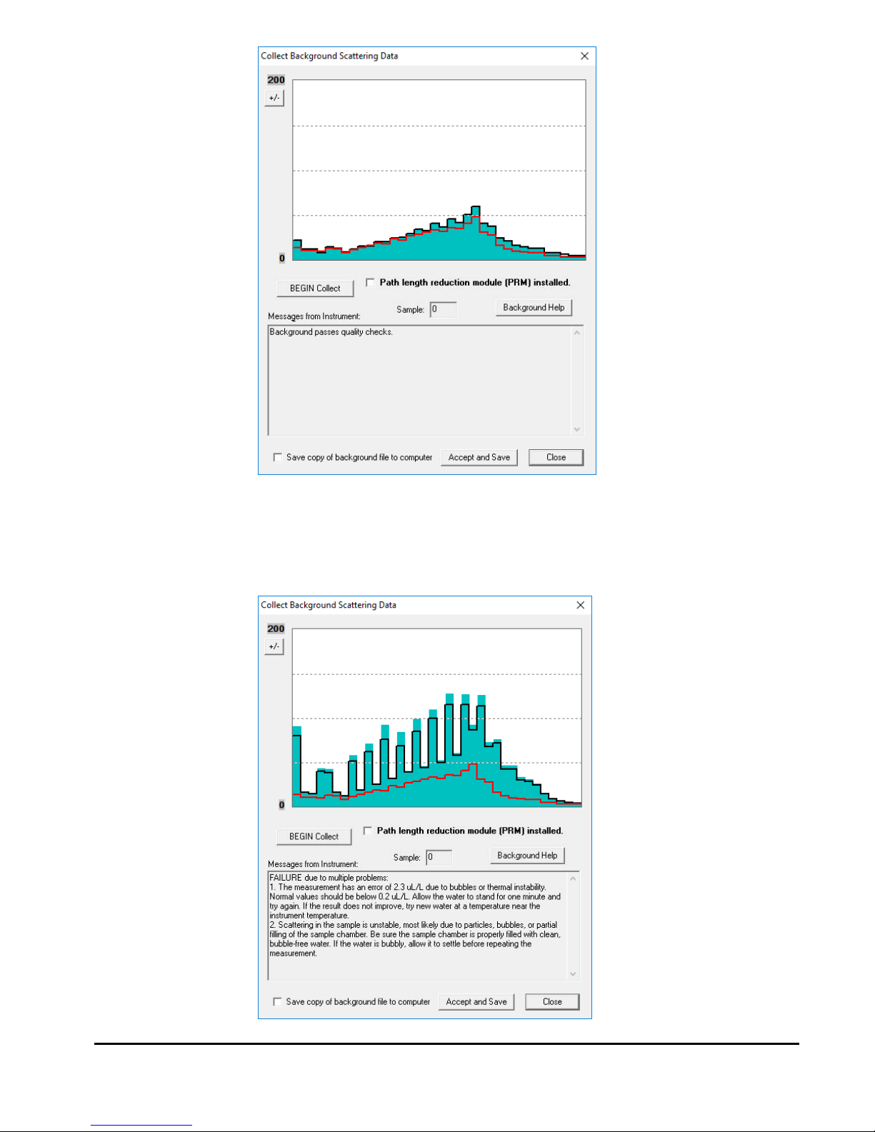
The background scattering measurement is critical to good instrument
performance. It is especially critical for clean water applications where
the optical transmission is greater than 90% over the 2.5cm path. The
background scattering will also check the overall health of the
instrument. It will verify that all of the systems are functioning and that
the optics is still in alignment. The current background will be acquired
and displayed relative to the factory background scattering for the
instrument. The image below shows an example of this display. It is
opened by either selecting Collect Background Scatter Data from the
LISST menu or by pressing the button on the toolbar.
The factory background file will be automatically acquired from the
instrument and displayed as a red line on the screen. Tips for
collecting a background are also displayed on the screen. Pressing the
‘Background Help’ button will open a PDF with additional information
about background measurements. When the BEGIN Collect button is
pressed 20 samples will be displayed to the screen as they are
acquired.
LISST-200X User’s Manual LISST-200X Introduction and Tutorial Page 15
The graph shows the value of the 36 light scattering detectors. The
red line is the factory values, the black line is the current measurement
and the solid bars are the average of all 20 measurements. If the
background is close to factory levels the message displayed will
indicate a pass or acceptable background.

LISST-200X User’s Manual LISST-200X Introduction and Tutorial Page 16
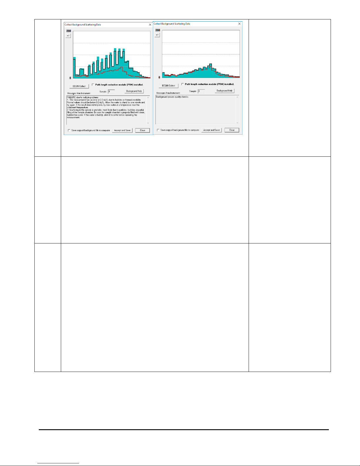
If the water or windows are not clean or if there is a problem with the
instrument, error messages and suggested actions will be displayed.
Dirty water or windows will generally cause higher values across the
middle rings. Large bubbles or particles in the water can cause higher
values on the inner rings or left hand side of the display. High values
on the inner rings combined with a lower transmitted laser power value
can also be an indication of optical misalignment.
If needed you can update the background, such as after cleaning the
windows or replacing the water, by pressing the BEGIN Collect button
again.
In general, the lower the background values the better the
background. The goal is to get values that are at the same values as
factory line. However, as the instrument is used the background may
increase due to small scratches and slight alignment changes. It may
not be possible to get the background down to the original factory
values.
If the values are acceptable the values can be saved both onboard the
instrument and to a file on your computer. The LISST-200X handles
the background files differently than the LISST-100X. The background
file is stored on the instrument and is saved as part of every data file
that is recorded. When processing a data file the background will be
automatically extracted and used during processing. Saving, tracking
and selecting a background file to use for processing is no longer
required. The background stored on the instrument will continue to be
saved in new data files until a new background is recorded.
NOTE: If you have already saved a background file, then decide to do
another one and you click Accept and Save, the background file on the
instrument will be overwritten without any warning.
If you wish to store a background into file on your computer as well as
on the instrument, check the ‘Save copy of background to computer’.
You will be prompted for location to save the file when you press the
‘Accept and Save’ button. It is not necessary to store the background
on your computer, however, these saved backgrounds can be used
during processing instead of the background saved in the data file.
Step 10:
Configuring
Instrument for
Deployment
The Sampling Program window is used to configure the deployment
parameters. To open the window, choose Configure Sampling
Program from the LISST menu or press the button on the tool bar.
A window similar to the one shown will appear. The window has four
tabs: Instrument Status, Operating Mode, Start Condition, and Stop
Condition.

LISST-200X User’s Manual LISST-200X Introduction and Tutorial Page 17
The Instrument Status page shows a summary of the instrument’s
current configuration. It also allows previously saved instrument
configuration files (.LOP files) to be loaded on to the instrument. The
ability to save the current settings to a file is also available. The. The
Comments windows allows for entering data about the current
configuration, for example metadata relating to the current settings.
Step 11: Setting
Operating Mode
By selecting the Operating Mode Tab at the top of the main window
the screen below appears. This screen is used to set the type of
sampling; Fixed Sample Rate or Burst. You can also select the
samples per average and sample rates on this screen.

LISST-200X User’s Manual LISST-200X Introduction and Tutorial Page 18
Burst and Fixed
Rate Modes
The Burst and Fixed Sample Rate modes are used to save data to a
raw data file on board the instrument. The icons next to the various
values give a better understanding of their meaning. The software
automatically checks the values entered to make sure that there is
no conflict. For example, when a ‘Sample to be Average of’ value is
entered, the minimum sample interval is computed. If this value is
less than the minimum permitted the value will be changed to the
minimum and the text will turn red.
The LISST-200X measures internally at ~20 Hz, but the data cannot
be stored to the data logger at this rate. The individual measurements
are averaged into a sample, and it is this sample average that is
stored at a maximum sample rate of 1 Hz. For the example shown
above, the instrument is set to sample in the Fixed Sample Rate mode
at a 1 Hz rate with 10 measurements per average. This average is
obtained in 0.53 seconds.
AutoStart
If the AutoStart check box is selected, the LISST-200X will start the
sampling program when power is applied to the instrument. If this is
not selected the user must send the ‘GO’ command to start the
sampling programing after apply power.
NOTE: AutoStart will not occur if the power is connected to
LISST-200X in low power sleep mode.
Step 12: Setting
Start Conditions
After selecting the Operating mode the start and stop conditions can
be selected. Choose the Start Condition tab at the top of the window.
There are five options: Depth, Time, External Mechanical Switch,

LISST-200X User’s Manual LISST-200X Introduction and Tutorial Page 19
External Digital Input, and Time Delay. Select the mode by clicking on
the button next to its label. Select the correct parameters as required.
For this example let’s select the External Mechanical Switch Start
Condition.
Step 13: Setting
Stop Conditions
Similarly the Stop conditions can also be selected. Click on the Stop
Condition Tab to open the Stop Condition window. The available stop
conditions are: Depth, Time. External Mechanical Switch, External
Digital Input, Fixed number of Samples, and Memory Full (<less than
6.5 V).
For this example, choose the External Mechanical Switch as the Stop
condition.
After selecting the Stop Conditions, click the APPLY button to
complete the configuration. This will transfer the settings to the
instrument. Then return to the Instrument Status page by clicking on
the Instrument Status Tab. It may take several seconds to configure
the sampling parameters on the LISST-200X. The status bar at the
bottom of the main window will indicate when a process is underway:
The status bar will return to ‘Ready’ when the process is completed:
Step 14: Saving
Settings for
The Instrument Status Page will now display the summary of the
settings that have been selected. These settings can be saved for

LISST-200X User’s Manual LISST-200X Introduction and Tutorial Page 20
Future Use
later use by selecting the ‘Save Configuration as .LOP File’. A file
name will be prompted for. The file will be given an LOP extension
which will identify it as a LISST Operating Procedure File. Comments
can be entered before saving in the box below the summary.
Previously saved LOP files can be opened using the ‘Load .LOP File’
button.
Press the OK button to complete the configuration.
Step 15:
Background File
Warning
If the background file onboard the instrument is more than 6 hours old,
a File Warning dialog box will appear, alerting you that final data
quality could be compromised. Select from the 2 options (collect a new
background or accept the risk and continue).
Step 16: Start
Instrument
The instrument is now configured for deployment, however, it is not
yet running.
You MUST start the instrument in order to start the samping program
you just configured. If you do not do that, the LISST will never start
sampling or react to the start and stop conditions.
Note that starting the instrument is not necessarily the same as
starting sampling (unless you have a delay start of 0 minutes set as
your start condition). For example, if you have selected the mechanical
switch as the start condition, the instrument will only react to the swtich
after the sampling program has been started. Only then will actual

LISST-200X User’s Manual LISST-200X Introduction and Tutorial Page 21
sampling begin.
For convience, you can select to open the terminal window or zero the
depth sensor before starting the sampling program. We recommend
selecting to open the terminal window, so you can confirm the
sampling program has been started.
If you select the Cancel button, the message below appears, informing
you how you can start the instrument.
When the instrument has been started, depending upon the Start
Conditions, text will be displayed approximately every 30 seconds in
the terminal window. At this point the user will know that the instrument
is running and is ready to be deployed. For our example it will be
displaying a message that reads “Waiting for Mechanical Switch ON
signal”.
While waiting for the start condition the LED on the connector endcap
will double blink every few seconds to alert the user that the instrument
is running but not yet sampling. During sampling the LED will
illuminate during the actual measurement of an averaged sample. For
example if the sampling is set for 1 Hz sampling with measurements
per average set to 20 then the LED will blink once per second. If
settings are set for a 30 second average every 15 minutes then the
LED will illuminate for 30 seconds every 15 minutes.
Step 17:
Collecting Data
For our example we can move the white plastic lever on the endcap to
the “1“ position. Sampling will start. If the Terminal window is still
open, text will be displayed as the instrument acquires data. Data
collection will continue until the Stop Conditions are met. In our case,
until the switch lever is returned to the “0” position.

LISST-200X User’s Manual LISST-200X Introduction and Tutorial Page 22
If the Start and Stop Conditions are set to Depth, External Mechanical
Switch, or External Digital Input the program will return to checking for
the Start Condition. This will only be true if the Start and Stop
conditions match. For example, Depth Start and Depth Stop. For nonmatching Start and Stop Conditions, such as fixed number of samples
or Time Stop, the program will terminate and the instrument will go into
a low power sleep mode.
To stop a running program, or wake it from low power sleep mode, use
the Stop button on the Terminal window or the button on the tool
bar.
It is good practice to always send a Stop command to the instrument
before attempting any other communication with the instrument.
Step 18:
Downloading
Data
The instrument has now stored data in the on-board memory card.
Pressing the Instrument Query Button , will display the instrument
status, including the number of samples saved. To download the data
to your computer select Download Data From LISST from the LISST
menu or choose the , button from the toolbar. A list of files will
appear:
Choose the files to offload by clicking on them while holding down the
CTRL key. The Shift key can also be used to select a range of files.
Select OK and then choose a location to save the files to.

LISST-200X User’s Manual LISST-200X Introduction and Tutorial Page 23
The files will be saved with names in the following format:
Ldddhhmm.RBN, where ddd is the day of the year, hh is the hour, and
mm is the minute that the file was first written to. As the data is
downloading a Transfer Status window will appear. The data is
offloaded at 115K baud.
If you click the cancel button in the upper right corner of the transfer
window the current file transfer (and any remaining file transfers) will
be cancelled.
Step 19:
Processing Raw
Data
We now have the data transferred from the instrument to the PC. To
process the data file choose Process Raw Data from the File menu or
press the button on the toolbar.
Note: You can also choose to open a raw data file using Process Raw
Data (Select Background). Use this option to manually select a
background saved on your computer to use during processing instead
of the background saved in the data file. There is also an option to do
batch processing of a large number of files at one time. Both of these
methods of processing data are discussed in more detail in the LISST200X User’s Manual.
You will be prompted to select the raw data file to open. Raw data files
have the extension .RBN, and are offloaded directly from the LISST200X data logger. Below is list of the file types you can expect to see
when using the SOP software.

LISST-200X User’s Manual LISST-200X Introduction and Tutorial Page 24
Extension
Discription
Format
.RBN
Raw Data
Binary
.RTX
Raw Data
ASCII
.PBN
Processed Data
Binary
.CSV
Processed Data
ASCII
.BGT
Background File
ASCII
.LOP
Operating Procedure
ASCII
Next, specify the output file name for the processed data. Note that a
.PBN file is always created. Output of other file types (.CSV or .RTX)
depends on the selections in the Settings selection in the File menu.
Every LISST-200X data file contains all the necessary information to
process the file. Therefore, the software will automatically determine
the instrument serial number, factory background, current background
and other instrument specific parameters.
A raw data file display will be generated for your selected data file.
The range of samples to process can be selected by entering values in
the Select First and Select Last boxes. The default selection is to
process the complete file. Press the Process File button to convert the
raw file into processed size distributions. For more details on the
available options when this window is open please see the detailed
Instruction for Processing Raw data files. When the processing is

LISST-200X User’s Manual LISST-200X Introduction and Tutorial Page 25
complete the button label will change to read Finished.
Step 20: Viewing
Processed
Results
Processed data files are stored as ASCII files (.CSV) and as binary
files (.PBN). The PBN files can be opened in the software and the size
distribution viewed on the screen. To open a processed Particle Size
Distribution file choose Display Particle Distribution File from the File
menu or press the button on the toolbar. A display similar to the
one below will open. The left hand figure will display a bar chart
showing the volume concentration in each of the 36 log spaced size
classes. The right hand plot will be the cumulative concentration. To
view the samples as a movie press the Start Display button. The
slider bar next to the button adjusts the refresh rate. The First, Prev,
Next, and Last buttons allow you to step through the measurements
one frame at a time. When the last frame is reached the movie display
will stop. Use the First button to return to the first sample and press
the Stop Display button to restart the display.
To view the value of the auxiliary parameters, such as depth and

LISST-200X User’s Manual LISST-200X Introduction and Tutorial Page 26
transmitted laser power, select the Show Auxiliary Parameter from the
View menu.
Step 21:
Opening a Real
Time Session
The LISST-SOP software also supports the ability to acquire, process,
and display size data it in real time. The Start and Stop conditions will
not be used and therefore their settings are not relevant.
Before opening a real time session you should collect a new
background and store it onboard the instrument. The real time session
will use the last background stored on the instrument to process the
data in real time. Therefore, you must ensure the background on the
instrument is up to date before continuing.
To open the Real-Time session, choose Collect Realtime Data from
the LISST menu or press the button. Choose an output PBN file.
A display very similar to viewing a processed PBN file will be
displayed.

LISST-200X User’s Manual LISST-200X Introduction and Tutorial Page 27
Use the Start Collection button to start and stop continuous data
collection. The slider bar controls the data acquisition time.
The Measurements Per Average text box allows you to adjust the
number of measurements that will be averaged together before the
display is updated. The default is 10. Higher values can be used
however it may cause a delay that lasts longer than your selected
interval time.
The Scale +/- Button adjusts the Particle Size Distribution scale. The
Save Single Sample button records a single sample to an ASCII file.
The Next button is used if the continuous data collection mode is not
being used. Pressing the next button will command the LISST to make
a measurement and transmit the data to the SOP for display.
The Spherical / Random Shape radio buttons can be selected in order
to display the results as being processed under the assumption that
the particles are spheres or randomly shaped (natural grains) particles.
The Auxiliary Parameters window can be opened during the Real-Time
session so that the values of various parameters such as depth and
transmission can be monitored. The raw scattering values on the
detector rings can also be viewed by selecting View Rings from the
View menu. A typical display is shown below.

LISST-200X User’s Manual LISST-200X Introduction and Tutorial Page 28
The view rings display is also available when processing a Raw Data
file. However, it is not available when viewing a processed Size
Distribution file.
Deploying the
LISST-200X in
the Field
The above steps should have given you a good understanding on the
how to operate the LISST-200X. More details on all of the steps can
be found in the User’s Manual following this tutorial. The following
steps go into deploying the instrument in the field.
Step 22:
Preparing for
Transport
The LISST-200X has been designed to be a robust field instrument.
However, it is still a highly sensitive optical instrument and needs to be
treated with care. This is especially true during shipping. The LISST200X is shipped in a custom case with specially designed foam
cushioning. Anytime the instrument is transported it should be in this
case. We highly recommend using air shipping when possible to
eliminate the extended vibrations that ground shipping can cause.
Because the LISST-200X does not have an internal battery there is no
need to worry about putting the instrument into low power sleep mode.
You can simply disconnect it from the battery pack.
The Large External Battery Pack, which has alkaline batteries, can be
stored for extended period when fresh batteries are installed.
The Small External Battery Pack, which has NiMH rechargeable
batteries, should be opened and the batteries removed during
transport. There are not restrictions on shipping NiMH batteries.
However, the batteries will have a small drain when installed in the
Small Battery housing. Therefore it is recommended that they be

LISST-200X User’s Manual LISST-200X Introduction and Tutorial Page 29
removed until the battery is ready to be used. The batteries should
also be stored in a fully charged state.
The LISST-200X can be pre-programmed with the desired sampling
program such as start and stop conditions and sampling rates. These
settings will remain in non-volatile memory until power is applied.
Therefore it is possible to prepare the instrument for sampling before
shipping it out. It is even possible to program the instrument to
automatically start upon power up. This is described in the next step.
Step 23:
Configuring
AutoStart
The LISST-200X can be configured to start running the sampling
program upon power up. In some situations this ability can be quite
helpful as you do not need to connect the instrument to the PC to start
the sampling. The instrument can be preconfigured with the desired
settings and the wait for the battery to be plugged in or external power
from the CTD to be present before looking for the Start Condition.
To configure the LISST-200X to start its sampling program upon power
up use the AS command (short for Auto Start). The AS command can
be issued when the 200X> prompt is displayed in the Terminal
Window. When AutoStart is enabled a message will be displayed as
part of the Status command or the Query instrument results.
When the LISST-200X is powered up a message will be displayed to
the Terminal window (or via the RS232 interface) that will prompt the
user that the instrument will auto start in 5 seconds. Pressing the stop
key or sending two CTRL-C characters will stop the instrument from
starting and return to the 200X> prompt.
Step 24:
Connecting to
External
Sensors or
Instruments
The LISST-200X had the ability to connect to external sensors and
instruments such as other dataloggers or CTDs through the 6-pin
Auxiliary connector on the endcap. The details of using the Auxiliary
connector can be found in the Step-by-Step instructions on page 69.
In short, the Auxiliary connector can be configured in one of three
ways: 1) Analog and Digital inputs, 2) Dual Analog Inputs, or 3) Dual
Analog Outputs. When using the Analog or Digital inputs it is possible
to provide power to an external sensor. By default this power output is
switched off. It will need to be enabled before power will be available.
You can also configure the warmup time required for the sensor after
power is applied before sampling will begin.
The Analog Output configuration sends out two analog voltages, Mean
Size and Total Concentration. This summary information is updated
each time data for the full size distributions is recorded. When using
the Analog Output configuration power can be received through the
Auxiliary connector. The wiring of the connector is designed to match
the SeaBird CTD Auxiliary Input connector simplifying the connection.

LISST-200X User’s Manual LISST-200X Introduction and Tutorial Page 30

LISST-200X User’s Manual LISST-200X Operation Details Page 31
II. LISST-200X Operation Details
Section
Organization
This section contains detailed instructions for performing various
procedures. These are either in the form of step-by-step instructions or
detailed descriptions of the various aspects of instrument operation
(e.g. command list, instrument mounting and deployment).
General
Precautions
• LISST-200X is a sensitive optical instrument - please handle it
gently as you would handle a very expensive camera.
• Critical alignments may be disturbed if the instrument is
subjected to shock or rough handling.
• Evidence of shock/rough handling will void the warranty.
• Whenever in transit, store the instrument in the provided padded
shipping case.
• If placing the instrument vertically on the standoffs, be sure to do
so gently as the Compact Flash Memory Card inside may
otherwise come loose.
WARNING
The LISST-200X uses a laser diode emitting a maximum of 1 mW of
visible (red) light at a wavelength of 670nm. The laser beam under
normal circumstances is not a threat. However, if objects are placed in
the path of the laser beam, the light could be reflected into the eye
causing permanent damage.

LISST-200X User’s Manual LISST-200X Operation Details Page 32
D. Step by Step Procedures
1. Installing LISST-SOP Software
Software for the PC is used to configure the LISST-200X and for downloading and
processing the size distributions.
STEP
ACTION
RESULT
1
• The LISST-200X comes with a USB memory card.
Plug the provided memory card into a USB port on
your computer. Locate the ‘LISST-
SOP200X_Installer.exe’ executable on the memory
card. Note that this software it is not compatible with
Mac or Linux operating systems. Your operating
system must be Window XP or newer to run the SOP
software.
•
Installer was found on
LISST-200X memory
card
2
• Double click the ‘LISST-SOP200X_Installer.exe.’
Follow the onscreen instructions and the installer will
transfer the necessary files to your computer and
place a shortcut on your desktop and start menu. Do
not remove the memory card from your computer until
the installation is fully completed:
Installation of SOP
software in complete

LISST-200X User’s Manual LISST-200X Operation Details Page 33
2. Establishing Communication with the LISST-200X
Establish communication with LISST-200X using the supplied software and USB cable.
Communicating with the LISST-200X via the LISST-SOP software should be automatic.
Should there be a problem you can use these step-by-step instructions to troubleshoot the
problem.
STEP
ACTION
RESULT
1
• If the SOP is open, close the program, then plug the
USB communication cable to the LISST-200X and to a
USB port on your computer.
LISST-200X will be
powered on
2
• After plugging the USB cable into your computer, the
drivers for the USB to serial converter should install
automatically. You should see a notification on the
task bar that drivers are being installed. If you are
unsure if the drivers installed, you can install the
drivers manually by running ‘CDM USB Drivers.exe’,
located on the memory card that came with your
instrument.
Computer is now set up
to communicate with
the LISST-200X
3
• After the driver installation is compete, open the
LISST-SOP200X software.
SOP software appears
onscreen
4
• Open Serial Port Settings from the Communications
menu.
• Select the port your LISST-200X is connected to from
the dropdown menu next to ‘Serial Port.’ The Baud
Rate and File Offload Baud Rate should stay at their
default values, 9600 and 115200, respectively. Save
the settings by pressing the ‘OK’ button.
• If you have trouble finding the right port, open the
Device Manger on your computer. Unplug and then replug the USB cable into your computer. The port that
appears in the Device Manger when you plug in the
USB cable is the port you need to select in the SOP
software. If no port appears, go back to step 2 and
reinstall the USB drivers.
SOP software will be
configured to connect to
the LISST-200X
5
• Open the port by selecting Connect from the
Communication menu or pressing the button.
Communication port is
now open

LISST-200X User’s Manual LISST-200X Operation Details Page 34
6
• After connecting, may need to wake your instrument
from sleep before continuing. To wake up the
instrument select Wake Up LISST from the LISST
menu or press the button. A dialog box will appear
counting down the maximum time required for the
instrument to wake up. Upon wake up the instrument
status will be displayed. If the cable connections are
not correct or if the power is not getting to the
instrument a warning message will appear after the
time expires.
LISST-200X is awake
and ready to configured
or collect data

LISST-200X User’s Manual LISST-200X Operation Details Page 35
3. Saving and Evaluating Clean Water Backgrounds
In order to properly compute the size distribution, it is necessary to remove the light
scattering from the internal optics and window surfaces so that only the light scattering from
the particles of interest are used to compute the size distribution.
STEP
ACTION
RESULT
1
• Connect the instrument to the computer and establish
communication in the LISST-SOP200X program. (see
Step-by-Step Procedure: Establishing Communication
with the LISST-200X)
LISST-SOP open and
communicating with
LISST-200X.
2
• Clean instrument and install Clean Water Background
Test chamber.
• Fill with clean filtered water and make sure no bubbles
are in the water or on the windows.
• The water and instrument should be at the same
temperature. Using water a significantly different
temperature from the water can impact the quality of
the background.
• Stir the water well before obtaining a background to
make sure the water is well mixed.
• For the best Background, make sure the instrument is
clean; the water you use is filtered, and free of
bubbles. Temperature fluctuations in water will
seriously degrade the background. Use water at the
same temperature as the instrument. Stir well.
Optics submerged in
water
3
• Select Collect Background Scatter Data from the
LISST menu or press the button on the toolbar.
The factory background file will be automatically
acquired from the instrument and displayed on the
screen.
• If using the path length reduction module (PRM), you
must collect a background with the PRM installed. If
the PRM is installed, select the PRM checkbox in the
collect background window.
• When the BEGIN Collect button is pressed 20
samples will be displayed to the screen as they are
acquired.
Background collected
and displayed on the
screen
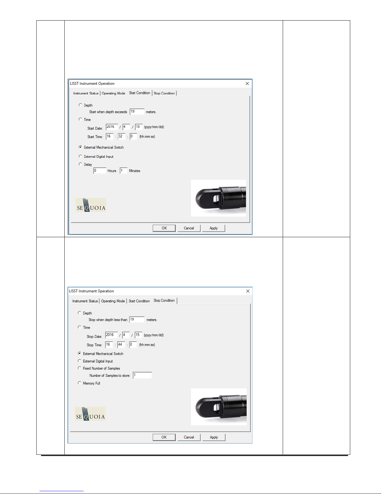
LISST-200X User’s Manual LISST-200X Operation Details Page 36
• The graph shows the value of the 36 light
scattering detectors. The red line is the factory
values, the black line is the current measurement
and the solid bars are the average of all 20
measurements. If the background is close to
factory levels the message displayed will indicate a
pass or acceptable background. Even if your new
background passes, but is significantly higher than
factory, clean the windows and repeat to verify you
have acquired the best possible result.
Acceptable Background
• If the water or windows are not clean or if there is a
problem with the instrument, error messages and
suggested actions will be displayed. Dirty water or
windows will generally cause higher values across the
middle rings. Large bubbles or particles in the water
can cause higher values on the inner rings or left hand
side of the display. High values on the inner rings
combined with a lower transmitted laser power value
can also be an indication of optical misalignment. If
needed you can update the background, such as after
cleaning the windows or replacing the water, by
pressing the BEGIN Collect button again.
Unacceptable
Background

LISST-200X User’s Manual LISST-200X Operation Details Page 37
4
• In general, the lower the background values the better
the background. The goal is to get values that are at
the same values as factory line. However, as the
instrument is used the background may increase due
to small scratches and slight alignment changes. It
may not be possible to get the background down to
the original factory values.
• Multiple cleanings or using better filtered water may be
required to get the best possible background.
• When you have an acceptable background press the
Accept and Save button to store the background on
the instrument. You also have the option to save the
background to a file on your computer. The LISST200X handles the background files differently than the
LISST-100X. The background file is stored on the
instrument and is saved as part of every data file that
is recorded. When processing a data file the
background will be automatically extracted and used
during processing. Saving, tracking and selecting a
background file to use for processing is no longer
required. The background stored on the instrument will
continued to be saved in new data files until a new
background is recorded.
• NOTE: If you have already saved a background file,
then decide to do another one and you click Accept
and Save, the background file on the instrument will
be overwritten without any warning.
• If you wish to store a background into file on your
computer as well as on the instrument, check the
‘Save copy of background to computer’. You will be
prompted for location to save the file when you
press the ‘Accept and Save’ button. It is not
necessary to store the background on your
computer, however, these saved backgrounds can
be used during processing instead of the
background saved in the data file.
Background Accepted
and saved.

LISST-200X User’s Manual LISST-200X Operation Details Page 38
4. Configuring Data Collection
The LISST-SOP software can be used to configure the Start and Stop Conditions, Fixed
Rate or Burst sampling and sample rates.
STEP
ACTION
RESULT
1
• Connect the instrument to the computer and establish
communication in the LISST-SOP200X program. (see Stepby-Step Procedure: Establishing Communication with the
LISST-200X)
LISST-SOP open
and
communicating
with LISST-200X.
2
• Open the Sampling Programs window by choosing
Operating Modes from the LISST menu or by pressing the
button on the toolbar.
• To set the LISST-200X data logger clock to the computer
clock press the Set Clock button. Press the Refresh Status
button to refresh the display.
Instrument Status
Displayed.
Clock set
3
• To load a pre-saved LISST Operating Procedure file (LOP)
click the Load .LOP File button.
• After the file is selected, the appropriate settings are loaded
but not yet configure on the instrument. To apply these
settings to the instrument press the Apply or OK buttons.
• LISST Operating Procedure files can be saved by clicking
the Save Configuration as .LOP File button. The setting
must have first been sent to the instrument using the Apply
button.
4
• By selecting the Operating Mode Tab at the top of the main
Operating Mode

LISST-200X User’s Manual LISST-200X Operation Details Page 39
window the screen below appears. This screen is used to
set the type of sampling: Fixed Rate or Burst. You can also
select the samples per average and sample rates on this
screen.
• The Burst and Fixed sample rate modes are used to set up
a sampling program that will save data onboard the
instrument. The icons next to the various values give a
better understanding of their meaning. The software
automatically checks the values entered to make sure that
there is no conflict. For example, when a Samples per
Average value is entered, the minimum sample interval is
computed. If this value is less than the minimum permitted
the value will be changed to the minimum and the text will
turn red. A similar test is done on the Burst Interval setting.
• If using the path length reduction module (PRM), check the
PRM checkbox. This checkbox must be selected to ensuring
the data are processed using the correct path length.
• If the AutoStart check box is selected, the LISST-200X will
start the sampling program when power is applied to the
instrument. If this is not selected the user must send the
‘GO’ command to start the sampling programing after apply
power.
• NOTE: Auto Start will not occur if the power is connected to LISST-200X
in low power sleep mode.
set
LISST-200X User’s Manual LISST-200X Operation Details Page 40
5
• Select the Start Conditions tab to configure when the
instrument will begin sampling.
• There are five options: Depth, Time, External Mechanical
Switch, External Digital Input, and Time Delay. Select the
mode by clicking on the button next to the its label. Select
the correct parameters as required.
Start Condition
Set
6
• Choose the Stop Conditions Tab to select the conditions
when sampling should stop.
• The available stop conditions are: Depth, Time. External
Mechanical Switch, External Digital Input, Fixed number of
samples, and Memory Full.
• If the Stop Condition is Depth, External Mechanical Switch,
Stop Condition
Set

LISST-200X User’s Manual LISST-200X Operation Details Page 41
or External Digital Input and the Start Condition is also one
of these three options the Base Program on the instrument
will return to waiting for the Start condition. For example, if
the start and stop conditions were set to External
Mechanical Switch then multiple sampling sessions can be
obtained by flipping the switch on and off. This is useful
when doing profiles. It eliminates the need to communicate
with the instrument between profiles.
7
• Select Apply or OK buttons to configure the instrument with
the current settings. If the Apply button is pressed the
program will return to the current window. Returning to the
Instrument Status window will display a summary of the
current settings.
8
• When the OK button is pressed, an alert will apear that
shows the time and date of your last background
measurment. If the background is more than 6 hours old, it
will alert you that final data quality could be compromised.
Select from the 2 options (collect a new background or
accept and continue).
• For best results, the background file should ALWAYS be
taken as close as possible to the deployment.
• If using the path length reduction module (PRM), this alert
may also warn you if your background was collected without
the PRM installed. If you are deploying the instrument with
the PRM installed, the clean water background must also be
collected using the PRM.
Confirm
Background
Measurement

LISST-200X User’s Manual LISST-200X Operation Details Page 42
9
• If the background file is accepted, the instrument is now
configured for deployment, however, the sampling
program running.
• You MUST start the sampling program in order to collect
data. If you do not do that, the LISST will never start
sampling or react to the start and stop conditions.
• Note that starting the sampling program is not necessarily
the same as starting sampling (unless you have a delay start
of 0 minutes set as your start condition). For example, if you
have selected the mechanical switch as the start condition,
the instrument will only react to the swtich after the sampling
program has been started. Only then will actual sampling
begin.
• For convience, you can select to open the terminal window
or zero the depth sensor before starting the sampling
program. We recommend selecting to open the terminal
window, so you can confirm the sampling program has been
started.
• If you select the Cancel button, the message below appears,
informing you how you can start the instrument.
Start Sampling
Program

LISST-200X User’s Manual LISST-200X Operation Details Page 43
10
• Clicking the Start button instead of the Cancel button will
start the sampling program immediately. In other words, the
instrument will begin waiting for the start condition. If the
start condition has already been met, the instrument will
start sampling immediately.
11
• The instrument will display text to the terminal window as it
is running to confirm that it is running and to indicate where
it is in the sampling cycle. Once the program is confirmed to
be running and waiting for the correct start conditions, the
LISST-SOP program can be closed and the communications
cable can be disconnected. Be sure to replace the
connector cap before deployment.
View Instrument
Messages in
Terminal Window

LISST-200X User’s Manual LISST-200X Operation Details Page 44
5. Using the Small External Battery Pack
The LISST-200X comes with a Small External Battery Pack that can be used for short term
deployments. The instructions in this section describe how to use the Small Battery
including installing and charging the NiMH rechargeable batteries.
STEP
ACTION
RESULT
1
• The LISST-200X Small External Battery Pack uses
two rechargeable NiMH D-cell batteries. Four of the
1.5V 10000mAh batteries and a charger are included
with the battery pack. The batteries are not installed
when the instrument a new instrument is shipped. It is
recommend that the batteries be removed from the
battery housing when not in use. Leaving the
batteries in the battery housing will cause the batteries
to discharge and could cause damage to the cells.
• Fully charge the batteries using the provided charger.
Fully discharged batteries will take about 8 hours to
charge.
Batteries fully charged.
2
• The Small Battery housing is made of plastic and has
an endcap with two underwater connectors and two
captive thumbscrews on one end.
• Loosen the thumbscrews. Note that the screws will
not need to be fully removed. They are designed to
be removed from the main housing but still remain
attached to the endcap. The screws can be removed
if you continue to rotate the screws through the
threaded holes in the endcap.
• Slide the endcap with battery holder attached out of
the main housing.
Battery open and ready
for batteries

LISST-200X User’s Manual LISST-200X Operation Details Page 45
3
• Slide the clear cover off of the battery holder and
install the two D cell batteries. The orientation of the
batteries is shown on a label on the battery holder.
• Slide the clear cover over the batteries such that the
rubber pad is pushing against the batteries as shown
in the picture above
Batteries installed.
4
• Check that the o-ring in the endcap and the mating
surface on the main housing are clean. Lightly grease
with silicone grease as needed.
• Carefully insert the assembly back into the main
housing until the o-ring makes contact with the
housing. Align the thumbscrews with the holes in the
main housing and push the endcap on until it is flush
with the housing.
• Tighten the thumbscrews by hand (DO NOT USE
ANY TOOL). DO NOT OVERTIGHTEN.
Battery assembled and
ready for use.

LISST-200X User’s Manual LISST-200X Operation Details Page 46
5
• The battery pack can be connected to the LISST-200X
using the provided 5-pin Male to 5-pin Female cable.
• Connect the Male end of the cable to the Female
Bulkhead connector on the Small Battery Pack.
• Connect the other end of the cable to the 5-pin Male
bulkhead on the LISST-200X.
• Power is now going to the LISST-200X. If AutoStart is
enabled the instrument may be looking for the start
condition.
Instrument is powered
and ready to collect
data
6
• If desired connect the Communications cable to the
male 5-pin bulkhead connector on the Small Battery
Pack. Communications will pass through the battery
to the LISST-200X.
• The battery and communications cables are shown
below.

LISST-200X User’s Manual LISST-200X Operation Details Page 47
6. Using the Large External Battery Pack
The Large External Battery Pack is used to provide power to the LISST-200X for long term
deployments or extended profiling operations.
STEP
ACTION
RESULT
1
• The LISST-200X Large External Battery is shipped
with 16 Alkaline D batteries pre-installed and is ready
for use. The following steps describe how to open
the battery and replace the batteries. Skip to Step X to
connect the battery to the LISST-200X.
• The new alkaline batteries can be left in the battery
housing for storage. However, it is not recommended
that fully discharged batteries be left in the battery
housing during long term storage.
Battery ready to use
when shipped.
2
• To access and replace the batteries in the Large
Battery pack you will need remove the endcap with the
connectors and handle.
• Remove the four 6-32 X ¾ long socket head cap
screws from the connector endcap using the provided
7/64” ball driver. Remove the screws uniformly or hold
the cap down against the light spring force.
Endcap ready for
removal

LISST-200X User’s Manual LISST-200X Operation Details Page 48
3
• Pull out the connector endcap. There are no wires or
other connections. Set the endcap to the side.
• Remove the batteries making note of their orientation.
• Insert the batteries into the pressure case. Labels on
the inside surface of the center divider will guide you
on the correct orientation of the batteries for each
stack.
Endcap removed and
batteries replaced.
4
• Inspect the o-ring on the endcap and the seating
surface on the pressure case to make sure there is no
debris that could affect the seal. Lightly grease the
surfaces as needed.
• Align the tab in the center of the endcap to the slot in
the post in the center of the pressure case
Endcap re-installed
5
• Screw the connector endcap onto the pressure case
with the four 6-32 x ¾ socket head cap screws. If
necessary, apply anti-seize compound onto the
threads.
Battery assembled and
ready for use.

LISST-200X User’s Manual LISST-200X Operation Details Page 49
6
• The battery pack can be connected to the LISST-200X
using the provided 5-pin Male to 5-pin Female cable.
• Connect the Male end of the cable to the Female
Bulkhead connector on the Large Battery Pack. The
connector will be labeled with “TO LISST”.
• Connect the other end of the cable to the 5-pin Male
bulkhead on the LISST-200X.
• Power is now going to the LISST-200X. If AutoStart is
enabled the instrument may be looking for the start
condition.
Instrument is powered
and ready to collect
data

LISST-200X User’s Manual LISST-200X Operation Details Page 50
7
• If desired connect the Communications cable to the
male 5-pin bulkhead connector on the Large Battery
Pack which is labeled “TO PC”. Communications will
pass through the battery to the LISST-200X.
• The battery and communications cables are shown
below.

LISST-200X User’s Manual LISST-200X Operation Details Page 51
7. Offloading and Deleting Data Files from Internal Memory
Data collected using the LISST-200X is stored on the internal data logger. This section
describes how to offload and delete files from the internal data logger.
STEP
ACTION
RESULT
1
• Connect the instrument to the computer and establish
communication in the LISST-SOP200X program. (see
Step-by-Step Procedure: Establishing Communication
with the LISST-200X)
.LISST-SOP open and
communicating with
LISST-200X.
2
• Select Download Data From LISST or Delete Data
From LISST from the LISST menu or click on the
offload or erase icons in the toolbar. This will
open up a window showing the data files currently
stored onboard the instrument.
Shows a list of files
currently stored
onboard the instrument
3
• Select individual or multiple files to delete or offload
(by holding down either shift or ctrl). Press ‘OK.’
Select files to delete or
offload
4
• A dialog box with either confirm the files to be deleted
or ask you to select a location on your computer to
offload the files to. After pressing ‘OK’ the files will
then be offloaded or deleted.
Files are offloaded or
deleted

LISST-200X User’s Manual LISST-200X Operation Details Page 52
8. Processing a Single Raw Data File
Data that has been downloaded from the datalogger is in a raw binary file (.RBN extension).
It must be processed into particle size by the LISST-SOP program.
STEP
ACTION
RESULT
1
• Start the LISST-SOP200X program
Program started.
2
• Select Settings from the File menu and click on the
Output Tab. The window below will appear prompting
for the desired output to use for the future data
processing. This selection must be made BEFORE
starting the processing command.
Select file types to be
created.
• NOTE: A binary PBN file is always created when
processing raw data. This is used to display the
processed data to the screen using the software.
• The CSV file is a space delimited ASCII file containing
the fully processed and calibrated data. This is useful
for loading into spreadsheets such as Excel etc.
• The RTX file is a space delimited ASCII file containing
the raw data from the LISST-200X data logger. This is
useful for looking at the raw data in a spreadsheet
such as Excel etc.
3
• You must also select the inversion model to be used
when processing the data: Spherical, randomly
shaped or both.
• For a description of the particle models, see Appendix
G: Spherical and Random Shape Particle Models.
• If you have selected Randomly shaped Particle
Inversion Model, the processed files will have an’ _rs’
suffix
Select inversion
method(s) to be used –
spherical, randomly
shaped or both.

LISST-200X User’s Manual LISST-200X Operation Details Page 53
4
• Select Process Raw Data or Process Raw Data
(Select Background) from the File menu. Standard raw
data processing will use the background file contained
in the .RBN file. If you would like to use a different
background file than the one in the RBN file, use the
Process Raw Data (Select Background) option. If you
use this option, you will be prompted for a .BGT file
first.
• You will be asked to select the .RBN file you would
like to process.
Select to process a file
using the background in
the data file or an
external .BGT file
5
• Next, select the output data file name. The default file
name shown is the same as the raw file name but with
a .PBN extension. You can change this name if you
wish.
• If other output types are selected they will
automatically have the same base name but with
different extensions.
• Note: file types other than the default PBN file must
have been selected before selecting Process Raw
Data from the File menu (See step 2).
Name out output file.

LISST-200X User’s Manual LISST-200X Operation Details Page 54
6
• A display similar to the one shown below will appear.
• The top portion of the display is a graphical
representation of the raw data from the 36 rings. The
value of the 36 rings is represented as a vertical line,
with time moving from left to right.
Main data processing
selection window
displayed to the screen.
• The lower portion of the display shows the time history
of some of the Auxiliary parameters. This can be
useful for determining when the instrument came out
of the water, when a particular profile was started, or
for determining what range of the raw file to process.
To change which Auxiliary parameters are displayed,
choose the Aux Params tab from the Settings window.
• Note that only 400 samples of the Auxiliary
Parameters are displayed at a time. Use the Next and
Previous buttons to move through the complete data
file. The triangles on the lower edge of the upper
display will indicate where in the complete data file the
currently displayed section is located.
7
• Additional information is stored in the data file.
Selecting the Show Auxiliary Parameters from the
View menu opens a window that displays this
additional information. The information displayed is for
the sample located at the position of the cursor (the
vertical pink line) in the lower plot of the raw data
display. You can click on the lower plot to move the
cursor to a new location. An example of this window
is shown below.
Auxiliary parameter
window displayed.

LISST-200X User’s Manual LISST-200X Operation Details Page 55
8
• The raw scattering values can be graphically
displayed by selecting the View Rings command from
the View menu. As with the Auxiliary Parameters, the
cursor indicates which sample is being displayed. You
can change what type of data is displayed in this
window by going to the View Rings tab of the Settings
menu
Value of rings for
current frame
displayed.
9
• To select the range of raw data to process position the
cursor at the desired starting sample. The display at
the lower portion of the screen will show the current
sample number. Pressing the Select First button will
set the current cursor position as the starting point for
processing. Similarly selecting Select Last will set the
Range to process
selected.

LISST-200X User’s Manual LISST-200X Operation Details Page 56
end point for processing. Use the Next and Previous
buttons scroll through the complete data file. The
Select First and Select Last points do not need to be
on the same displayed plot.
10
• After selecting the range to process press the Process
File button. The display will show the processing
progress and the Process File button text will change
to Finished when the processing is complete. The
window can now be closed.
Processing Completed.
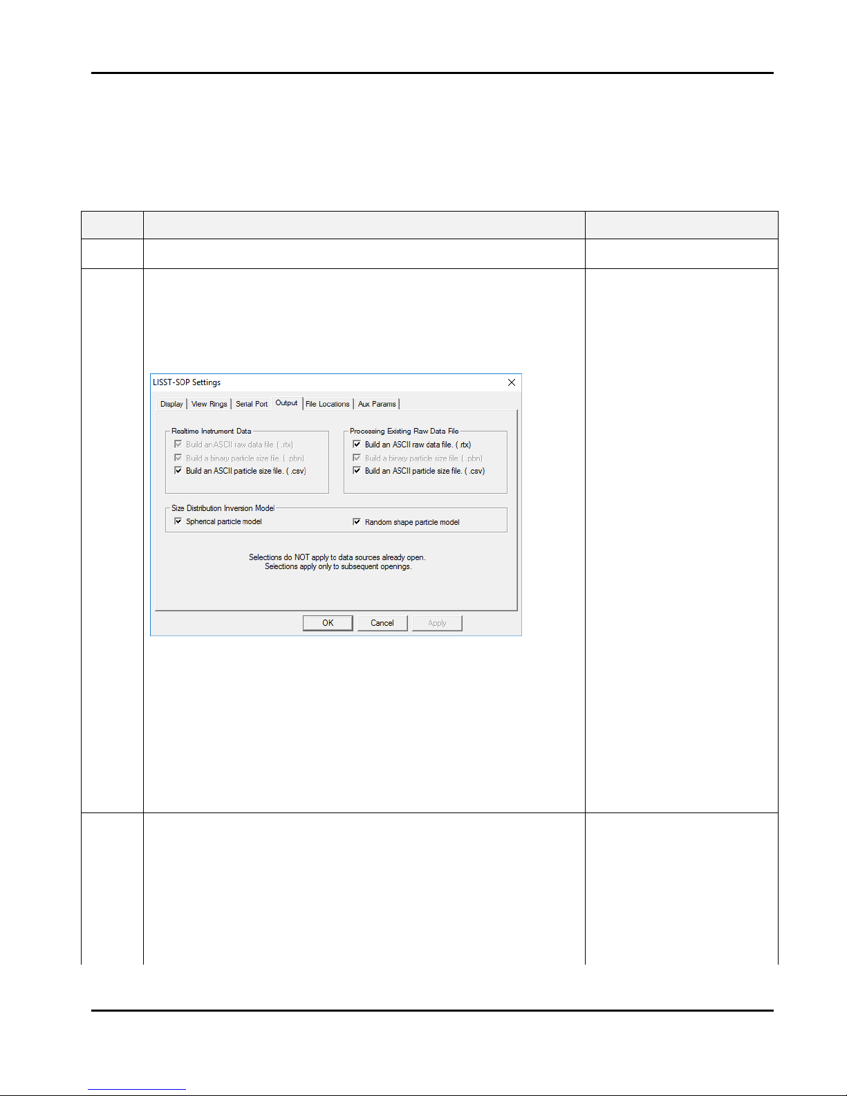
LISST-200X User’s Manual LISST-200X Operation Details Page 57
9. Batch Processing Multiple Raw Data Files
Data that has been downloaded from the datalogger is in a raw binary file (.RBN extension).
It must be processed into particle size by the LISST-SOP program. If you have multiple raw
data files to process (e.g. from a series of profiling deployments), follow these processing
steps that allows you to process all files in one operation.
STEP
ACTION
RESULT
1
• Start the LISST-SOP200X program
Program started.
2
• Select Settings from the File menu and click on the
Output Tab. The window below will appear prompting
for the desired output to use for the future data
processing. This selection must be made BEFORE
starting the processing command.
• NOTE: A binary PBN file is always created when
processing raw data. This is used to display the
processed data to the screen.
• The CSV file is a space delimited ASCII file containing
all the processed data.
• The RTX file is a space delimited ASCII file containing
the raw data from the LISST-200X data logger.
Select file types to be
created.
3
• You must also select the inversion model to be used
with the real time data processing: Spherical,
randomly shaped or both.
Select inversion
method(s) to be used –
spherical, randomly
shaped or both..
• For a description of the two particle models, see
Appendix G: Spherical and Random Shape Particle
Models.

LISST-200X User’s Manual LISST-200X Operation Details Page 58
• If you have selected Randomly shaped Particle
Inversion Model, the processed files will have an’ _rs’
suffix
4
• Select Process Raw Data (Batch) from the File menu.
6
• By default, batch processing will use the background
stored in the raw data files to process the data. If you
would like to use an external .BGT file, uncheck the
‘Use background contained in files’ and select a .BGT
file.
Select source of
background files

LISST-200X User’s Manual LISST-200X Operation Details Page 59
7
• Select the directory where your raw data files (.RBN)
are located. Click the select button and navigate to the
desired folder and select it. Please note that ALL raw
data files in the folder will be processed. If you wish to
only process a selection of files in a folder, these files
must be copied to an empty directory, which must then
be selected as the Raw Files Directory.
• By default, the Output Files Directory will be the same
as the Raw Files Directory. However, if you wish to
change this to another directory, then click the select
button in order to choose another directory.
• The Raw Files List box now shows all the raw data
files (.RBN) that are in your Raw Files Directory, while
the Output Files Box shows .CSV, .PBN, and .RTX
files that may already exist in the Output Files
Directory.
• You cannot change the output file names. The file
name of the processed files will be the same as that of
the raw data files, but with a different extension (e.g.
.CSV, .PBN or .RTX). If you have selected Randomly
shaped Particle Inversion Model, the processed files
will have an’ _rs’ suffix.
• Note: file types other than the default PBN file must
have been selected before starting the batch
processing. See step 2.
Raw Files Directory
selected.

LISST-200X User’s Manual LISST-200X Operation Details Page 60
8
• You can now click the Process Raw Files button and
all raw data files will be processed. The processed
files will show up in the Output Files window. Note that
the files processed using the randomly shaped
inversion method have an ‘_rs’ suffix.
Batch processing..
9
• Click the close button in the bottom right when you are
done.
Close the batch
processing window.

LISST-200X User’s Manual LISST-200X Operation Details Page 61
10. View Processed Data File
After processing of the data into a Particle Size Distribution file (.PBN extension) the data
can be viewed to the screen. This step-by-step procedure covers the viewing of data and
optional displays.
STEP
ACTION
RESULT
1
• Start LISST-SOP200X program
Program started.
2
• Select Display Particle Distribution File from the File
menu.
Open Particle
Distribution File
selected.
3
• Select the processed data file (.PBN) from the file
selection window. Double click the file or type the file
name and press Open.
Processed data file
selected.
4
• After selecting the processed file, a window similar to
the one shown below will appear.
Particle size
distribution displayed
on screen
• The left hand display is the volume distribution in units
of micro-liters/liter in each size class. The right hand
display is the Cumulative Concentration.
5
• Only a single sample is displayed at a time. By using
the buttons on the bottom of the display it is possible to
manually or automatically step through the data file.
The Start Display button will step through the data file
by updating the display at a fixed rate. The rate is set
by the slider bar next to the Start Display button.
Scroll through
measurements
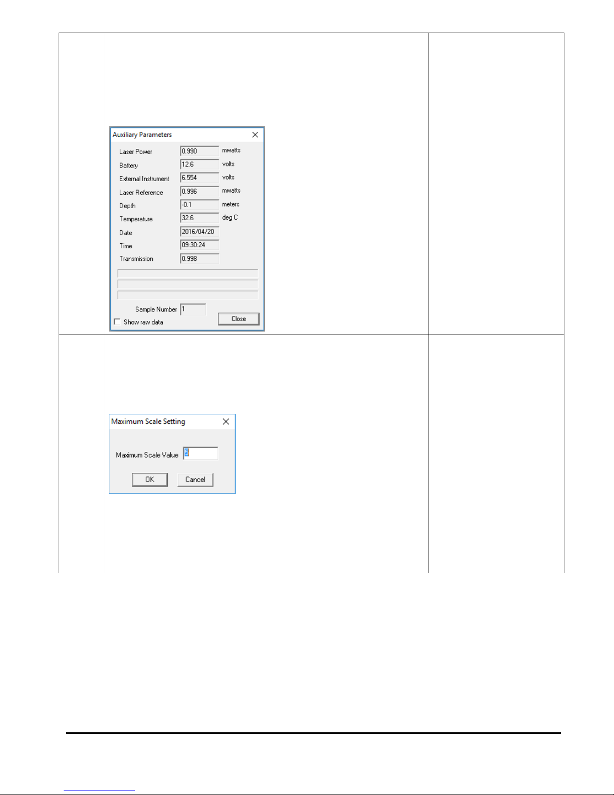
LISST-200X User’s Manual LISST-200X Operation Details Page 62
6
• Additional information is stored in the processed data
file. The Auxiliary parameter window displays these
values for the current sample. They will update when
the sample number is changed. The window is opened
by selecting Show Auxiliary Parameters from the View
menu. An example of this window is shown below.
View auxiliary
parameters
7
• The scale of the Volume Distribution plot can be
changed by using the Scale +/- button. After selecting
the button a display similar to the one shown below will
prompt you for the maximum concentration for the Yaxis of the plot.
Display setting
modified.
• Other options are also available for customizing the
display such as changing the header and footer text or
adding lines to show the mean and standard deviation.
These features are located on the Display tab of the
Settings window as shown below.

LISST-200X User’s Manual LISST-200X Operation Details Page 63
8
• The current display can be sent to the printer by
choosing Print from the File menu.
• Print Preview and Print Setup are also available.
Display printed.
9
• When finished viewing the processed data close the
window.
Viewing of data
complete.

LISST-200X User’s Manual LISST-200X Operation Details Page 64
11. Data Quality Control
Making sure your data make sense.
STEP
ACTION
RESULT
1
• Follow steps 1-6 in the previous section: View
Processed Data File and look at the Auxiliary
Parameter Frame
Data file loaded and
Auxiliary Parameter
frame shown.
2
3
• The first thing to look for is to make sure that the
Laser Reference box is displaying numbers different
than 0.
• In the example above Laser Reference is at 8.943
mW, but this number can vary from instrument to
instrument, and will also vary as the instrument
becomes older and, to some extent, with
temperature. Values around 0.5-2 mW are the most
common values.
• Laser Reference should never be 0 (or very close to
0, e.g. 0.02 mW). If this is the case the laser is most
likely dead. In this case only your pressure data and
temperature data will be any good. The laser must
be replaced. Contact Sequoia or your local
distributor for instructions on what to do.
• Tip: If you selected ‘Create .CSV file’ when
processing your data, you can load the .CSV file
into Excel or another spreadsheet and easily check
all the Laser Reference values - the Laser
Reference value is in column number 40.
Check your Laser
Reference values –
they *MUST* be >>
than 0.

LISST-200X User’s Manual LISST-200X Operation Details Page 65
4
• The next thing to look for is to check the
Transmission values. The transmission must be a
number between 0 and 1.
• It is physically impossible for the transmission to be
negative or larger than 1 (one).
• Tip: The transmission value is in column 56 of the
.CSV file.
• If transmission shows up as being larger than 1
(one), then your measurement is most likely taken
in very clear water and/or you have a bad zscat
measurement obtained with dirty water and/or dirty
windows.
• If your zscat measurement was obtained using dirty
water, it may be possible to redo the zscat using
clean water and re-process the data, then check to
see if the transmission values drop below 1 (one).
It is physically
impossible for the
Transmission value to
be less than 0 (zero) or
larger than 1 (one).
5
• If your transmission values generally are in the
0.98-0.995 range, your measurements are taken in
very clear water.
• This means that the signal-to-noise ratio will be low,
and the data may have a lot of noise in them, but
can most likely still be used.
Transmission values
very close to 1 yields
noisy data.
6
• If your transmission values are < 0.10 (or 10%), the
water is too turbid. Disregard these data.
Data with transmission
values < 10% should
be disregarded.
7
• If your transmission values are > 0.995 (or 99.5%),
the water is too clear. Disregard these data.
Data with transmission
values > 99.5% should
be disregarded.
8
Summarizing
• Disregard data if laser reference is 0 or very close
to 0 (laser is dead, contact Sequoia).
• Disregard data if transmission is > 0.995 (> 99.5%).
• Disregard data if transmission is < 0.10 (< 10%).
• Be wary of data collected at transmission values
between 0.98 and 0.995 – low signal-to-noise ratio.
• Be wary of data collected at transmission values
between 0.30 and 0.10 – generally decreasing data
quality as the transmission decreases below 0.30
(30%).
Quick quide for data
QC

LISST-200X User’s Manual LISST-200X Operation Details Page 66
12. Simple Real-Time Data Processing
This step-by-step procedure covers the acquisition, display and storage of processed data in
real time.
STEP
ACTION
RESULT
1
• Connect the instrument to the computer and establish
communication in the LISST-SOP200X program. (see
Step-by-Step Procedure: Establishing Communication
with the LISST-200X)
Communication
established.
2
• Before starting a Real-Time session the output file options
must be set. This must be done before selecting Collect
Realtime Data. Select the Output tab in the Settings
menu. The window below will appear.
Output file type
selected.
A binary PBN file must be selected before any other file type
will be stored. This is used to display the processed data to
the screen.
• The CSV type is a comma delimited file containing all the
processed data.
• The RTX file is a comma delimited file containing the raw
data from the data logger.
• You must also select the inversion model to be used with
the real time data processing: Spherical, randomly
shaped or both. For details on these selections, see
Appendix G: Spherical and Random Shape Particle
Models.

LISST-200X User’s Manual LISST-200X Operation Details Page 67
3
• The background currently stored onboard the instrument
will be used to process the data as it is collected in real
time.
• Be sure to collect a new background and store it onboard
the instrument before beginning a real time session
Background is
current
4
• Select Collect Realtime Data from the LISST menu or
press the button.
Open Instrument
selected.
5
• A display will appear on the screen. It is similar to the
main window of the View Processed Data function.
• The ‘Measurement Per Average’ text box allows you to
adjust the number of measurements that will be averaged
before the display is updated. The default is 10. Higher
values can be used however it may cause a delay that
lasts longer than your selected interval time.
• By selecting the Next button the window will be updated
with the current size distribution. Note that if the water is
clean the display may not show any volume distribution.
• The Sample Number value displayed underneath the
plots will increment each time a sample is saved.
• The radio buttons for labeled ‘Spherical’ and ‘Random
Shape’ allow you to display the volume distribution
calculated with either the spherical or random shape
particle model. The radio buttons only effect the display
and have no effect on the data that is saved in the .CSV
file. If you selected both particle models in part 2, data
from both models will be saved to your computer
regardless of the radio button selection.

LISST-200X User’s Manual LISST-200X Operation Details Page 68
6
• The Start Collection button function is similar to its use in
viewing processed data. The SOP will automatically
acquire data at a fixed rate. The slider next to the Start
Collection button controls the sample speed. Note that the
interval time may be limited by the measurement average
you have selected.
Start Collection
button pressed and
samples updating
automatically.
7
• The Auxiliary parameter window can be opened to display
the current values of the auxiliary parameters such as
pressure and temperature. Open the window by selecting
the Show Auxiliary Parameters from the View menu.
Auxiliary Parameter
window opened.
8
• The scale of the Volume Distribution plot can be changed
by using the Scale +/- button. After selecting the button a
display similar to the one shown below will prompt you for
the maximum concentration for the Y-axis of the plot.
Display setting
modified.
9
• The raw scattering values can be graphically display by
selecting View Rings from the View menu. An example of
this display is shown below.
Value of rings for
current frame
displayed.
10
• A single sample may be saved to a separate file by
pressing the Save Single Sample button
Averaged data
acquired and stored
to an ASCII file.
11
• Press the ‘Stop Collection’ button and close the window to
end the realtime session.
Stop data collection

LISST-200X User’s Manual LISST-200X Operation Details Page 69
13. Collecting Data from an External Analog Sensor
The LISST-200X can supply regulated 12V power to an external sensor, and measure one
or two analog voltages, depending on its hardware configuration and firmware settings. If
the 12V power output is activated, it will turn on each time the 200X collects a sample or
burst of samples, and turn off each time the 200X goes into a waiting state of more than a
few seconds. If using the 12V output, you can specify how long it should turn on before
sampling, as a warmup time for the sensor.
To provide these functions, the auxiliary connector on the LISST-200X must be in one of two
configurations: Analog & Digital Input (which provides a single analog input), or Dual Analog
Input configuration (which provides two).
STEP
ACTION
RESULT
1
• Determine current configuration of Auxiliary connector: in
LISST-SOP, select LISST->Show Instrument Status. Look
for the Endcap Configuration. If it is not one of the analoginput configurations, you will need to change it; contact
Sequoia for assistance.
Auxiliary
Connector
configuration
determined
2
• Make the appropriate connections between the 6-pin
auxiliary connector of the LISST-200X and your sensor. To
see the pin assignments, type the CONFIG command in the
LISST-SOP terminal wipage 77). Or see Appendix E:
Connector Pinouts for LISST-200X.
External sensor
connected
3
• Type SENSORPOWER into the terminal window, and
respond to its prompt to select the appropriate option.
• Type SENSORWARM in the terminal window to set a
warmup time (in seconds).
• WARNING: a USB cable may not provide enough power for
external sensors. Use a battery pack or other power source
to provide enough power to run external sensors.
Configured for
analog collection
4
• Set the standard sampling parameters to control the
sampling schedule and other options (see
• Configuring Data Collection on page 38).
Ready to collect
data

LISST-200X User’s Manual LISST-200X Operation Details Page 70
14. Configuring the LISST-200X as a Sensor for a CTD
The LISST-200X can operate as an analog-output auxiliary sensor for a CTD. For this
purpose the LISST-200X’s auxiliary six-pin connector must be in its “Dual Analog Output”
configuration. The two analog outputs represent the total volume concentration of particles,
and the Sauter mean diameter (SMD). These values are approximations for the
convenience of real-time display. For highest-quality data you will still need to offload and
process the detailed data from the LISST-200X after deployment.
The LISST-200X updates its analog outputs each time it collects a sample, at a maximum of
1 Hz.
STEP
ACTION
RESULT
1
• Determine current configuration of Auxiliary connector: in
LISST-SOP, select LISST->Show Instrument Status. Look
for the Endcap Configuration. If it is not in the Dual Analog
Output configuration, you will need to change it; contact
Sequoia for assistance.
Auxiliary
Connector
configuration
determined
2
• Make the appropriate connections between the 6-pin
auxiliary connector of the LISST-200X and your sensor. To
see the pin assignments, type the CONFIG command in the
LISST-SOP terminal window (see LISST-200X Command
Details on page 77), or see Appendix E: Connector Pinouts
for LISST-200X.
Connected to
CTD
3
• In LISST-SOP, set the sampling parameters as follows (see
• Configuring Data Collection on page 38):
o Operating mode: Fixed sample rate
o Sample to be average of 20 measurements
o Sample interval: 1 second
o Automatically start sampling program upon power up
Start condition: delay 0 minutes
o Stop condition: memory full
200X will collect
data at 1 Hz
whenever the
CTD supplies
power to it

LISST-200X User’s Manual LISST-200X Operation Details Page 71
E. Instrument Communication
Overview
The cables Sequoia supplies with the LISST-200X send data through a
standard USB port. However, the LISST-200X itself communicates
through RS-232 serial protocol. The 5-pin male connector on the
LISST-200X carries the RS-232 signals (and power). The cables
incorporate adapters that convert between RS-232 and USB.
If you use a different cable that does not include the RS-232-to-USB
adapter, you can use an external adapter, or connect directly to an RS232 port if your computer has one (which is rare on any recent
computer). In Windows, both RS-232 and USB connections will appear
as COM ports. To establish communication with LISST-SOP or other
software, you must set the software to communication with the correct
COM port.
If interfacing to a data logger or controller system other than a Windows
computer, you will likely also use a direct RS-232 connection.
The RS232 link communicates at 9600 baud, 8 data bits, No parity, and
1 stop bit. For offloading data files, the LISST-SOP software uses
YMODEM protocol at 115K baud. The transfer rate can be changed in
the settings of the LISST-SOP software. A slower speed may be
required when downloading data over cables longer than a few meters.
Using the LISSTSOP Terminal
Window
In the LISST-SOP software, you can open a terminal window to directly
view communications with the LISST-200X, and enter commands.
When the LISST-200X is connected and the terminal window is the
front window, the LISST-200X should respond to pressing the enter key
with the L200X:> prompt. If the instrument is in the deep sleep mode,
you can wake it by pressing the Stop button.
Pressing the Start button will begin the collection of data using the
current sampling program (see
Configuring Data Collection).
Direct
Commands
In most cases, LISST-SOP software will be used to configure and
operate the LISST-200X. However, some functions are available only
through direct commands in the terminal window. Also, in some
applications the LISST-200X may need to communicate to another
datalogger or custom program. For this purpose, a large set of
commands is available to operate the instrument. See the LISST-200X
Command Summary on page 75 for detailed descriptions of each
command.

LISST-200X User’s Manual LISST-200X Operation Details Page 72
Start Condition
The LISST-SOP software or two letter commands can configure the
LISST-200X with one of five Start conditions:
1. Depth,
2. Time,
3. External Mechanical Switch,
4. External Digital Input, and
5. Time Delay.
The details of each condition are described below.
Depth Start
The built-in depth sensor of the LISST-200X is used to check the
current depth to determine if the desired start depth has been
exceeded. The instrument is powered up and 5 measurements of the
depth are averaged over a two-second period. If the depth exceeds the
threshold the program will proceed to the data collection routine. If the
depth does not exceed the threshold the instrument will power down
and wait 28 seconds before checking the depth again. The program
will continue checking until the depth is exceeded or until the program
is stopped.
Time Start
The program will check the current time every second and compare it
to the Start Time. If the Start Time is equal to or earlier than the current
time the program will go directly to the data collection routine. It will
continue checking the time until the Start Time is reached or until the
program is stopped.
External
Mechanical
Switch Start
The LISST-200X has a white plastic lever on the endcap. This lever
has a magnet imbedded in it. This magnet can activate a switch inside
the pressure case. The base program looks at the status of this switch
once a second. If the switch is in the on or “1” positions the program
will go directly to the data collection routine. It will continue checking
the switch status until the switch is moved to the “0” position or until the
program is stopped. When in the “0” position the lever is up against the
zinc anode.
External Digital
Input Start
If the auxiliary connector is configured for analog and digital inputs (see
Appendix E: Connector Pinouts for LISST-200X), pin 2 of the 6-pin
connector is the digital input. The program will check the status of the
digital input once a second. If the digital input is greater than 2 volts
(relative to digital ground, pin1) the program will go directly to the data
collection routine. It will continue checking the status of the digital input
until voltage drops below 0.7 volts or until the program is stopped.

LISST-200X User’s Manual LISST-200X Operation Details Page 73
Time Delay Start
The time delay start condition will cause the program to wait the
specified number of seconds before continuing on to the data collection
routine.
Data Collection
Routine
The LISST-SOP software can configure the sampling program with one
of six Stop conditions: Depth, Time. External Mechanical Switch,
External Digital Input, Fixed number of samples, and Maximum
Memory or Low Battery. The details of each condition are described
below.
Stop Condition
The LISST-SOP software can configure the LISST-200X with one of six
stop conditions:
1. Depth,
2. Time,
3. External Mechanical Switch,
4. External Digital Input,
5. Fixed number of samples, and
6. Memory full.
When storing data in the Fixed Sample Rate mode the Stop conditions
are checked after each averaged sample has been saved. When
storing data in the Burst mode the Stop conditions are only checked
after a full Burst has been completed. The Start and Stop conditions
have no effect on the Real-time sampling mode. The details of each
condition are described below.
Depth Stop
The depth sensor of the LISST-200X is used to check the current depth
to determine if it is less than the desired Stop depth. If the depth is less
than the threshold the sampling will stop. If the Start Condition is Depth
Start the program will return to checking for the start depth. For all
other Start Conditions the when the current depth is less than the
threshold the LISST-200X will stop and go into deep sleep.
Time Stop
The program will check the current time after each sample or burst and
compare it to the Start Time. If the Start Time is equal to or later than
the current time, it will stop and go into deep sleep.

LISST-200X User’s Manual LISST-200X Operation Details Page 74
External
Mechanical
Switch Stop
After each sample or burst the status of the Switch lever is checked. If
the switch lever is in the off or “0” position sampling will stop. If the
Start Condition is a Switch Start the program will return to checking the
start condition. For all other Start conditions the instrument will stop and
go into deep sleep.
External Digital
Input Stop
The status of the digital 1 input is checked after each sample or burst. If
the voltage at the input is less than 0.7 volts the sampling will stop. If
the Start Condition is a Digital Input Start the program will return to
checking the start condition. For all other Start conditions the
instrument will stop and go into deep sleep.
Fixed Number of
Samples
The program will acquire a fixed number of samples before stopping.
When the number of samples to be saved has been reached the
program will stop and go into deep sleep.
Memory Full
Sampling will continue until the memory is full, or the power input falls.
If the memory fills, the instrument will go into deep sleep.

LISST-200X User’s Manual LISST-200X Operation Details Page 75
F. LISST-200X Command Summary
NOTE: Command are shown in upper case for clarity, but are not case-sensitive.
Display
Commands
CONFIG
Display instrument hardware configuration information
DD, DIR
Display current disk directory
DEPTH
Display current depth
DS
Display current instrument status information
DT
Display current time and date
HELP, ?
Display general help messages and command list
SW
Display mechanical switch position
TEMP
Display current temperature
VIN
Display input supply voltage
Setup
Commands
MODE, OM x
Set operating mode (burst or fixed-rate)
ST x, STARTCOND x
Set start condition.
TD x, STARTDATA x
Set start condition data
SP x, STOPCOND x
Set stop condition
PD x, STOPDATA x
Set stop condition Data
SI x
Set sample interval
MA x
Set samples per average equal to x
BI x
Set burst interval
SB x
Set samples per burst
SC yyyy/mm/dd hh:mm:ss
Set clock with time and date, where yyyy=year, mm=month,

LISST-200X User’s Manual LISST-200X Operation Details Page 76
dd=day, hh=hour(24 format), mm=minute, ss=seconds,
AS x
Set autostart
STOREDATA x
Suppress data storage (WARNING: can cause loss of data!)
ZD
Reset depth sensor offset
SENSORPOWER x t
Set whether power output turns on during logging
SENSORWARM t
Set external sensor power warmup time
Acquisition/Action
Commands
DL filename
Delete file
GO
Start data collection using current parameters
GX
Grab sample and transmit it
XR
Transmit raw data when average saved
ZS
Acquire 20 samples and evaluate them for quality.
ZZ
Go into deep sleep mode (minimum power consumption)

LISST-200X User’s Manual LISST-200X Operation Details Page 77
G. LISST-200X Command Details
1. Display Commands
CONFIG
Display instrument hardware configuration
Syntax:
CONFIG
Description:
The current hardware configuration including Auxiliary I/O connector
configuration
Example:
input: CONFIG
output:
Serial Number: 2001
Firmware Version: 1100 (1.100)
VCC: 59371
Full Path Length: 2500 (25 mm)
Eff. Path Length: 2500 (25 mm)
BioBlock Installed: 0
Start Condition: Digital input (4)
Start Condition Data: 0
Stop Condition: Switch (3)
Stop Condition Data: 0
Measurements Per Average: 10
Sample Interval: 1 seconds
Burst Mode: 0
Samples Per Burst: 5
Burst Interval: 25 minutes
Transmit Raw Data: 0
Lifetime Sample Count: 529554
Lifetime Laser On Time: 1703980 seconds
Endcap Configuration: 0 (Analog & digital in)
Wiring of MCBH6MP connector:
1: Ground
2: Digital input 1
3: Digital input 2
4: +12V output
5: Analog input 1
6: Ground

LISST-200X User’s Manual LISST-200X Operation Details Page 78
DD, DIR
Display Disk Directory
Syntax:
DD or DIR
Description:
Display current disk directory in DOS type format. Includes total bytes
used and bytes available.
Example:
input: DD
output:
LISST-200X Disk Directory
Volume in drive C is NONAME
Volume Serial Number is 778B-155F
Directory of C:\
L040305_.BIN 4,136 03-05-04 6:30p
L183705.BIN 1,672 03-05-04 6:37p
2 file(s) 5,808 bytes
0 dir(s) 15,933,440 bytes free
L200X:>
DEPTH
Display current depth
Syntax:
DEPTH
Description:
The current depth is displayed to the screen.
Example:
input: DEPTH
output: Current depth: 567.1 meters
DS
Display current status information
Syntax:
DS
Description:
The instrument settings and status are displayed to the screen.
Example:
input: DS
output:
LISST-200X Status and Settings
Serial number = 1004
Endcap Configuration: 0 (Analog & digital in)
Firmware Version 1.126 Apr 26 2016 18:45:52

LISST-200X User’s Manual LISST-200X Operation Details Page 79
Current Date/Time: 2016/04/27 10:27:02
Current Day of the Year: 118
Supply voltage: 12.00 V
Operating Mode: Burst Mode
AutoStart OFF
Delay Start with 0 minute delay
Measurements per Average: 10
Sample Interval: 1
Stop after 5 samples
External sensor power during logging: off
External sensor warmup time: 0 seconds
Free memory: 1023 Mbytes
input: DS 1
output:
LISST-200X Current Status and Settings
SN = 1004
OM = 0
ST = 5
TD = 0
SP = 5
PD = 0
MA = 10
SI = 1
BI = 1
SB = 1
BB = 0
AS = 0
SENSORPOWER = 0
SENSORWARM = 0
Current Time = 2016/04/27 10:32:15
Battery = 1200
Switch = 0
Memory= 1023639552 Bytes
Endcap = 0
DT
Display current time and date
Syntax:
DT
Description:
Displays current time and date to the screen.
Example:
input: DT
output: Date/Time: 2001/01/05 21:05:03

LISST-200X User’s Manual LISST-200X Operation Details Page 80
HELP, ?
Display general help messages and command list
Syntax:
HELP or ?
Description:
Displays the list of command to the screen.
Example:
input: HE
output: LISST-200X Commands (followed by 30 lines of text)
SW
Display current Mechanical Switch position
Syntax:
SW
Description:
The current position of the Mechanical Switch is displayed to the screen.
Example:
input: SW
output: Current Switch Position: 0
TEMP
Display current temperature
Syntax:
TEMP
Description:
The current temperature is displayed to the screen.
Example:
input: TEMP
output: Current temperature: 20.3 deg C
VIN
Display Battery Voltage
Syntax:
VIN
Description:
The current supply voltage is displayed to the screen.
Example:
input: VIN
output: Current Input Voltage: 8.90 volts

LISST-200X User’s Manual LISST-200X Operation Details Page 81
2. Setup Commands
OM
Set Operating Mode
Syntax:
MODE x or OM x
Description:
Sets the Operating Mode to one of the following types:
0 = Fixed rate
1 = Burst Mode
OM command only without a parameter will initiate a prompt for the
Operating mode.
Example:
input: OM 1
output: New Operating Mode: Burst Mode
ST,
STARTCON
D
Set Start Condition
Syntax:
ST x or STARTCOND x where x is the start condition code described
below
Description:
The ST command sets the start condition to be used when the GO
command is issued. The start condition options are:
1 = Depth Start
2 = Time/Date Start
3 = Mechanical Switch Start
4 = Digital Input Start
5 = Delay Start
If no value follows command, prompts will be displayed for the value.
After setting the start condition to Depth, Time or Delay, use STARTDATA
to set the applicable condition value.
Example:
input: ST 5
output: New Start Condition Setting: Delay Start

LISST-200X User’s Manual LISST-200X Operation Details Page 82
TD,
STARTDATA
Set Start Condition Data
Syntax:
TD x or STARTDATA x where x is the start condition data described
below
Description:
The TD command sets the start condition data to be used when the GO
command is issued. The start condition data is used with the Start
Condition setting as follows:
• If the Start Condition is Depth Start (option 1) the input will be start
depth in meters.
• If the start condition is set to Time/Date Start (option 2) the input for
TD will be the start date and time.
• If the Start Condition is Delay Start (option 5) the input will be time
delay in minutes.
• The TD setting is ignored for Mechanical Switch Start (option 3) or
Digital Input Start(option 4).
If no value follows command, prompts will be displayed for the value.
Example:
input: TD 3 (if Start Condition = 1 (Depth Start))
output: New Start Condition data = 3
Start Condition: Depth Start at 3 meters
input: TD 2016/12/31 23:59:59 (if Start Condition = 2 (Time/Date Start))
output: New Start Condition data = 2016/12/31 23:59:59
Start Condition: Time Start at 2016/12/31 23:59:59
Input: TD 2 (if Start Condition = 5 (Delay Start))
Output: New Start Condition data = 2
Start Condition: Delay Start with 2 minute delay
SP,
STOPCOND
Set Stop Condition
Syntax:
SP x or STOPDATA x, where x is the stop condition code described below
Description:
The SP command sets the stop condition to be used when collecting data.

LISST-200X User’s Manual LISST-200X Operation Details Page 83
The stop condition options are:
1 = Depth Stop
2 = Time/Date Stop
3 = Mechanical Switch Stop
4 = Digital Input Stop
5 = Number of Samples Stop
6 = Maximum memory or Low Battery Stop
If no value follows command, prompts will be displayed for the value. After
setting a stop condition of Depth, Time/Date or Number of Samples, use
STOPDATA to enter an appropriate parameter value.
Example:
input: SP 5
output: New Stop Condition Setting: Fixed Number Stop
PD
Set Stop Condition Data
Syntax:
PD x or STOPDATA x where x is the stop condition data as described
below
Description:
The PD command sets the stop condition data to be used when the
collection data. The stop condition data is used with the Stop Condition
settings as follows.
• If the Stop Condition is Depth Stop (option 1) the input will be stop
depth in meters.
• If the stop condition is set to Time/Date Stop (option 2) the input for
PD will be the stop date and time.
• If the Stop Condition is Fixed Number Stop (option 5) the input will
be the number of samples to collect before stopping.
• The PD setting is ignored for Mechanical Switch Stop (option 3),
Digital Input Stop (option 4) or Maximum memory or Low Battery
Stop (option 6).
Example:
input: PD 3 (if Stop Condition =1 (Depth Stop))
output: New Stop Condition data = 3
Stop Condition: Depth Stop at 3 meters
input: PD 2016/12/31 23:59:59 (if Stop Condition = 2 (Time/Date Stop))
output: New Stop Condition data = 2016/12/31 23:59:59
Stop Condition: Time Stop at 2016/12/31 23:59:59

LISST-200X User’s Manual LISST-200X Operation Details Page 84
input: PD 2 (if Stop Condition = 5 (Fixed Number of Samples Stop))
output: New Stop Condition data = 2
Stop Condition: Fixed number Stop at 2 samples
SI
Set Sample Interval
Syntax:
SI x, where x is the number of seconds between samples, from 1 to
10,000.
Description:
In either fixed-rate or burst mode, the sample interval is the number of
seconds between two consecutive samples, each composed as an
average of a number of measurements (specified by the MA command).
Example:
input: SI 5
output: New Seconds between Samples: 5
MA
Set measurements per average
Syntax:
MA x
The exact result depends on whether ambient light rejection (ALR) is
active. Starting with firmware version 1.4 (May, 2017), ALR is on by
default, and the actual number of samples averaged will be approximately
x/10. That is, MA 32 will result in 3 ALR cycles per average.
With or without ALR, 32 is the maximum MA value that allows 1 sample
per second.
Description:
Each recorded or displayed measurement is based on an average of
measurements. MA sets the number of measurements per.
If no value follows command, prompts will be displayed for the value.
Example:
input: MA 32
output: New Measurements per Average: 32
BI
Set Burst Interval
Syntax:
BI x, where x is the number of seconds between the start of 2

LISST-200X User’s Manual LISST-200X Operation Details Page 85
consecutive bursts, from 1 to 10,000 seconds.
Description:
In Burst Mode (MODE = 1), the burst interval is the number of seconds
between two consecutive bursts, each burst composed of a number of
samples per burst (specified by the SB command).
Example:
input: BI 900
output: New Seconds between Bursts: 900
SB
Set Samples per Burst
Syntax:
SB x, where x is the number of samples per burst.
Each sample is taken at the sample interval (in seconds) set by the SI
command.
If no value follows command, prompts will be displayed for the value.
Example:
input: SB 10
output: New Samples per Burst: 10
SC
Set Clock with time and date
Syntax:
SC yyyy/mm/dd hh:mm:ss
Where yyyy=year, mm=month, dd=day, hh=hour (24 hour format),
mm=minute, ss=seconds
If no values follow the “SC” or “sc” command, prompts for entering the
time and date will be displayed.
Example:
input: SC 2017/01/05 21:05:03
output: Command Data in SC is: 2017/01/05 21:05:03
Current Date/Time: 2017/01/05 21:05:03
AS
Enable Autostart Setting
Syntax:
AS x, where x is 1 (yes) or 0 (no)
Description:
With Autostart enabled, the firmware will immediately start the sampling

LISST-200X User’s Manual LISST-200X Operation Details Page 86
program when power is applied to the instrument.
Example:
input: AS 1
output: AutoStart will occur upon power up!
Cautions:
If Autostart is enabled, the user cannot talk to the instrument when
powering it up – it will immediately start sampling according to the SD
defaults. In order to stop sampling and establish normal communication,
the user must issue a stop command, by either pressing the STOP button
or issuing a CTRL-C command in the terminal window within a few
seconds of powering up the instrument.
SaveData
Save Data Setting
Syntax:
SAVEDATA x, where x is 1 or 0
Description:
The SaveData setting disables (x = 0) or enables (x = 1) data storage on
the internal drive. No Ldddhhmm.DAT file will be created if Save Data
mode is disabled.
It is intended to be used for long-term real-time deployments, where it
may not be desirable to have the data stored on the datalogger. It may be
desirable to disable data storage when exporting raw data to an external
data logger. See the XR command for configuring the raw data export
option.
Example:
input: SAVEDATA 1
output: Data will be stored after each sample!!!
input: SAVEDATA 0
output: Data will NOT be stored after each sample!!!
Cautions:
Be very careful that the correct store mode is selected before a
deployment where it is the intent to store the data internally on the
instrument!
Issue a DS command to verify the status of the store mode setting. A
warning will be displayed as part of the DS status if the store mode is
disabled:
WARNING: Data storage disabled. Data will not be saved!!!

LISST-200X User’s Manual LISST-200X Operation Details Page 87
ZD
Reset Depth Sensor Offset
Syntax:
ZD
Description:
The ZD (or zd) command resets the depth sensor offset so that the sensor
reads a depth of 0m at zero depth (in air). You must issue the ZD
command, then select 1 (yes) or 0 (no) to reset depth sensor
Example:
input: ZD
output: Depth Sensor Offset Reset Procedure Started.
Instrument must be at zero depth and similar temperature to field
conditions.
Do you wish to reset Depth Sensor offset? (1=yes,0=no): [0] ? 1
Previous offset was -14.03. New offset is -13.87.
Previous Depth was -0.15 meters.
New Depth using corrected offset is 0.00 meters.
Cautions:
None

LISST-200X User’s Manual LISST-200X Operation Details Page 88
3. Acquisition/Action commands
DL
Delete file from LISST memory
Syntax:
DL filename, where filename is the name of the file to be deleted.
Description:
DL command is used to delete file from the Compact flash module.
Wildcards such as *.* can be used.
Example:
Input: DL L159*.dat
Output: Are you sure (Y/N)…
Cautions:
WARNING: Make sure that the file being delete has already been
offloaded before deleting the file. Once the file is delete it can not be
recovered.
GO
Start Data Collection using current Settings
Syntax:
GO
Description:
Starts Fixed Rate or Burst Mode Data collection using current settings.
Example:
Input: GO
Output: Waiting for start conditions…
Cautions:
To stop data acquisition before it is complete press the Stop button or
CTRL-C.
GX
Grab sample and transmit it
Syntax:
GX
Description:
Acquires single averaged sample and displays the result to the screen.
Example:
Input: GX
Output: {
…. 36 ring values + 24 Aux parameters
}

LISST-200X User’s Manual LISST-200X Operation Details Page 89
Notes:
The GX command does not store the sample to a datafile.
XR
Transmit raw data during sampling
Syntax:
XR x, where x = 0 through 3
Description:
This command allows data to be transmitted to an external data system
during execution of the GO command, in one of several formats. The
default setting is 0, with data transmission turned off. Setting 1 sends raw
data in a multi-line text format; 2 sends a single line as a NMEAcompatible data sentence; 3 sends a single line of comma-separated
values. Contact Sequoia Scientific for complete details of these formats.
Example:
input: XR 1
output: Raw data WILL be transmitted when data is stored
Cautions:
Format 2 requires firmware 1.3 or later. Format 3 requires firmware 1.414
or later.
ZS
Collect and transmit background scattering data
Syntax:
ZS
Description:
Acquires 20 averaged sample and displays the result to the screen.
Evaluates the data for quality as a background measurement.
Example:
Input: ZS
Output: {
…. 36 ring values + 24 Aux parameters
}
repeat 20 times, then messages about the quality of the data.
Notes:
The ZS command does not store the sample to a datafile.
ZZ
Go into deep sleep mode (minimum power consumption)
Syntax:
ZZ

LISST-200X User’s Manual LISST-200X Operation Details Page 90
Description:
Sends LISST-200X in to low power sleep mode. Instrument will send a
message every 30 seconds to indicate it is sleeping. It can be wakened at
any time by sending 2 control-C characters about ½ second apart.
Example:
Input: ZZ
Output: Deep Sleep… Enter zz to wake up
Deep Sleep… Enter zz to wake up
Deep Sleep… Enter zz to wake up

LISST-200X User’s Manual LISST-200X Operation Details Page 91
H. Performance Optimization
This section contains information on optimizing the performance of the LISST-200X.
Optical
Alignment
The background measurement is the best source of information on the
current health of the LISST-200X. It provides information on the
current functionality of all of the major systems including laser, ring
detector, data collection electronics, and optical alignment. The LISST200X is a sensitive optical device. The laser must be aligned such that
the focused spot is centered on the hole in the center of the ring
detector. If this alignment in not correct the instrument will not function
correctly. The background measurement can easily provide the user
with information about the status of the alignment.
The first indicator of an alignment problem is a severe drop in the
currently transmitted laser power when compared to the factory laser
power. The laser power and laser reference values will change over
time but they should track together. If the value of the laser
power:laser reference ratio for your current background measurement
is less than 85% of the laser power:laser reference ratio from the
factory background file, misalignment may be occurring.
The second indictor of misalignment is high value on the inner rings.
The inner rings are shown on the left side of the background display.
The most important rings for misalignment indication are rings 1-4 in
the background scatter file. As the focused laser starts to move away
from the center of the ring detector it will scatter more light onto the
inner rings. This will cause the inner ring values to be much higher
than the factory values, and is also the reason for the decrease in
transmitted laser power.
It must be noted that low laser power or high inner rings may not
always indicate misalignment. Low laser power can also occur
because the windows or water is dirty or if there are bubbles on the
window. Large particles or bubbles can cause the inner rings to be
higher than factory values. All of the other possibilities must be
eliminated before it can be concluded that the instrument is misaligned.
The transmit optics on the LISST-200X do allow for the possibility of the
user adjusting the alignment. A written procedure can be provided for
this procedure. However, it is highly recommended that the need for
re-alignment be discussed with a trained Sequoia Scientific technical
service representative before attempting this procedure.
Background
Measurement
and its
Importance
As was discussed in earlier sections, the LISST-200X uses a custom
detector to measure light scattered at small angles from particles in
water. In order to measure only the scattered light contributed by the
particles, a measurement of the background scattering must be
obtained. This background scattering can come from a number of
areas. Scratches on the windows, imperfections on the optics, and
other sources all contribute to the scattered light. By subtracting this
background scattering from the measured data, a true measurement of

LISST-200X User’s Manual LISST-200X Operation Details Page 92
the light scattered from the particles can be obtained. The
measurement of background scattering is sometimes called a "ZSCAT".
The name comes from the fact that the measurement is obtained using
water with zero "scatterers" or particles.
It is very important that clean and bubble free water is used. The water
can be fresh or salt water. For most applications, it has been found
that steam-distilled water is sufficient. Steam-distilled water is typically
available in one-gallon containers. We have found that this distilled
water tends to be a bit cleaner than typical bottled or packaged water.
We buy steam-distilled drinking water and filter it through a 0.2µm filter.
A small volume horizontal chamber has been provided for submerging
the optics while acquiring a background. It is inserted between the
windows of the optics. The instrument should be placed horizontally on
the supplied white plastic supports. However, Plastic bags, Tupperware
or clean containers of any kind can be used to acquire a background.
The instrument’s optics end can be submerged in them vertically, as
long as the optics are completely submerged and there is no blockage
of the windows by bubbles or other objects.
Because the area surrounding the windows is submerged, it is
important to thoroughly clean and rinse this part of the instrument
before acquiring a background.
Toothbrush, liquid soap and water works well for cleaning the optical
end of the instrument; do not use abrasive powders, they will scratch
optics and destroy instrument performance.
The low concentration limit of LISST-200X is very sensitive to the
quality of the background scatter file. For this reason, when working in
low concentration water, it is very important that a good background file
be obtained with very clean water. As particle concentrations increase,
the relative signal-to-background noise ratio also increases, thus
reducing the importance of the background. However, a background
should always be collected before an experiment.
Watch for
Outgassing and
Bubbles
Another consideration when acquiring a background is "outgassing"
causing small bubbles to form on the instrument and windows.
Bubbles on the windows will greatly modify the scattering pattern,
rendering the background useless. Be sure to remove any bubbles
from the windows before acquiring a background. Use a squirt bottle or
pipette to blow the bubbles off the window.
Because the area surrounding the windows is submerged, it is
important to thoroughly clean and rinse this part of the instrument
before acquiring a background.
 Loading...