

Sepura SRG3500XB Mobile gateway accessories

sepura
Mobile & Gateway
Accessory i/f specification
SB-P-06-4066
PRODUCT BULLETIN
© SEPURA PLC 2011

SB-P-06-4066
sepura
Mobile & Gateway Accessory i/f
specification
30th July 2012
Page 2 of 39
Issue 7c
© Sepura plc 2011
Contents
LEGAL RESPONSIBILITIES........................................................................... 5
ISSUE HISTORY ............................................................................................. 6
PREFACE ........................................................................................................ 7
Introduction .............................................................................................................................. 7
Terminology ............................................................................................................................. 7
Abbreviations ........................................................................................................................... 7
Conventions ............................................................................................................................. 7
DECLARATION OF CONFORMITY ................................................................ 8
INTERFACE OVERVIEW .............................................................................. 10
Transceiver ............................................................................................................................. 10
Console ................................................................................................................................... 10
AIU Mk1 ................................................................................................................................... 11
AIU Mk2. .................................................................................................................................. 11
Example interconnect block diagram .................................................................................. 12
CONSOLE INTERFACE ................................................................................ 13
Connector details .................................................................................................................. 13
Transceiver connector. ......................................................................................................... 13
Console/AIU connector ......................................................................................................... 13
Signal details .......................................................................................................................... 14
Line Level Audio Support ..................................................................................................... 16
POWER SUPPLY INTERFACE ..................................................................... 19
Connector details .................................................................................................................. 19

SB-P-06-4066
sepura
Mobile & Gateway Accessory i/f
specification
30th July 2012
Page 3 of 39
Issue 7c
© Sepura plc 2011
Signal details .......................................................................................................................... 19
Speaker configurations ......................................................................................................... 21
AUDIO ACCESSORY INTERFACE (AAI) ..................................................... 22
Connector details .................................................................................................................. 22
Signal details .......................................................................................................................... 22
Audio Accessory Identity Table ........................................................................................... 24
Accessory Keys Table .......................................................................................................... 24
Audio gain .............................................................................................................................. 25
AIU MK 1 Jack Connectors ................................................................................................... 26
Connector Details .................................................................................................................. 26
Jack Signals ........................................................................................................................... 26
AIU MK 2 Jack Connectors ................................................................................................... 27
AAI2 – via jack connector ..................................................................................................... 27
RCI CONNECTIONS ..................................................................................... 29
Connector Details .................................................................................................................. 29
Signal details .......................................................................................................................... 29
DESK MOUNT UNIT CONNECTORS ........................................................... 31
Desk Microphone/Headset Connector................................................................................. 31
Connector Details .................................................................................................................. 31
Signals .................................................................................................................................... 31
Foot Switch Connector ......................................................................................................... 31
Connector Details .................................................................................................................. 31
Signals .................................................................................................................................... 32
Loudspeaker Connector ....................................................................................................... 32
DATA CONNECTOR INTERFACE ............................................................... 33
Connector details .................................................................................................................. 33

SB-P-06-4066
sepura
Mobile & Gateway Accessory i/f
specification
30th July 2012
Page 4 of 39
Issue 7c
© Sepura plc 2011
Signal details .......................................................................................................................... 33
ANTENNA’S .................................................................................................. 35
Connector details .................................................................................................................. 35
Signal details .......................................................................................................................... 35
GPS ANTENNA ................................................................ ............................. 36
Connector details .................................................................................................................. 36
Signal details .......................................................................................................................... 36
CONSOLE AND AIU CABLE SPECIFCATION ............................................ 37
Cableform Mechanical Details .............................................................................................. 37
Cable form Grommet ............................................................................................................. 38
NOTICE ......................................................................................................... 39
Contact Details ....................................................................................................................... 39

SB-P-06-4066
sepura
Mobile & Gateway Accessory i/f
specification
30th July 2012
Page 5 of 39
Issue 7c
© Sepura plc 2011
LEGAL RESPONSIBILITIES
The information in this document is subject to change without notice and describes only the
product defined in this document. This document is intended for the use of Sepura plc‘s
customers and/or other parties only for the purposes of the agreement or arrangement under
which this document is submitted, and no part of it may be reproduced or transmitted in any
form or means without the prior written permission of Sepura plc.
The document has been prepared to be used by professional and properly trained personnel,
and the customer and/or other party assumes full responsibility when using it. Sepura plc
welcomes customer and/or other party comments as part of the process of continuous
development and improvement of the documentation.
The information or statements given in this document concerning the suitability, capacity, or
performance of the mentioned hardware or software products cannot be considered binding
but shall be defined in the agreement or arrangement made between Sepura Plc and the
customer and/or other party.
However, Sepura plc has made all reasonable efforts to ensure that the instructions contained
in the document are adequate and free of material errors and omissions. Sepura plc will, if
necessary, explain issues which may not be covered by this document.
Sepura plc‘s liability for any errors in this document is limited to the documentary correction of
errors. Sepura plc will not be responsible in any event for errors in this document or for any
damages, incidental or consequential, (including monetary losses), that might arise from the
use of this document or the information in it.
This document and the product it describes are considered protected by copyright according
to the applicable laws.
Other product names mentioned in this document may be trademarks of their respective
companies, and they are mentioned for identification purposes only.
SB-P-06-4066
sepura
Mobile & Gateway Accessory i/f
specification
30th July 2012
Page 6 of 39
Issue 7c
© Sepura plc 2011
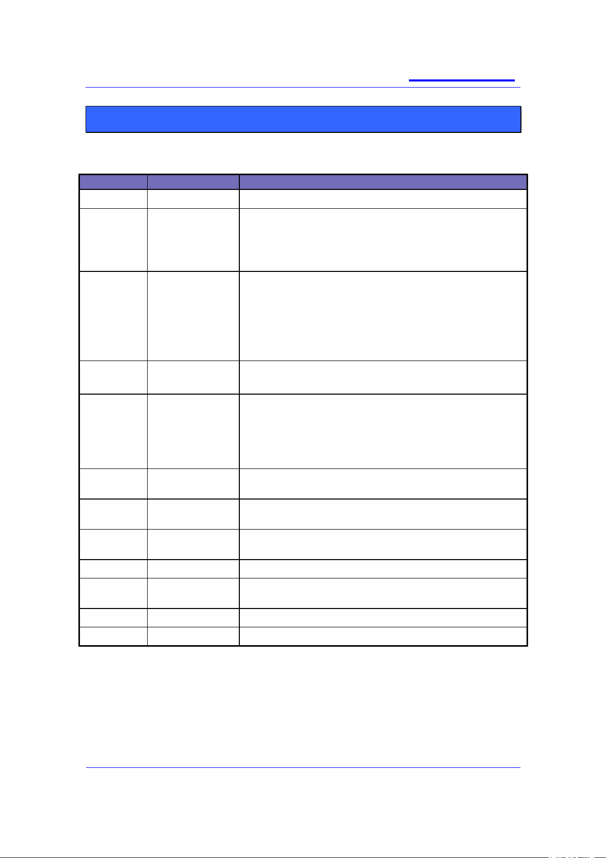
Version
Date
Change
Version 1
1st June 2006
Supersedes SB-P-05-4042
Version 2
24th July 2006
Added declaration of conformity statement.
Added abbreviations table.
Clarified difference between Mk1 and Mk2 AIU‘s.
Added cable form details.
Version 3
22nd Sept 2006
Clarified data interface = PEI port
Corrected AIU Mk1 and Mk2 contents re audio accessory
support
Clarified MIC and EAR on RCI port no longer supported
AIU Mk1 superseded by AIU Mk2
Added Input freq spec and levels for GPS antenna
Version 4
19th Jan 2007
3679 parameter details added
SRM/G2 and 3 digital I/O capability clarification.
Version 5
17th April 2007
Added reverse battery polarity comment and note re digital
input resistance.
Corrected block diagram GPS connector.
Added GPS LNA gain requirement
Version 6
17th Feb 2009
Incorporates V9 changes (AIS Issue 7 and 8 of the
development document)
Version 6a
6th May 2009
Added [ITU-T V.24] and [ITU-T V.28] RS232 serial data
compliant
Version 6b
13th Aug 2010
Added comment to section 6 regarding sidetone being
present for all accessories
Issue 7
15th Sept 2010
Corrected formatting issues found in issue 6b
Issue 7a
10th Jan 2011
Corrected hyperlink error on page 13 & 14. Added reference
for SCC AIS
Issue 7b
20th Jul 2011
Further tidy up of formatting
Issue 7c
30th Jul 2012
Corrected references to digital i/o on console (page10)
ISSUE HISTORY
SB-P-06-4066
sepura
Mobile & Gateway Accessory i/f
specification
30th July 2012
Page 7 of 39
Issue 7c
© Sepura plc 2011
Term
Definition
Signal names with lower case
―n‖.
These signals are active low.
Convention
Description
AAI
Audio Accessory Interfaces
AIU
Application Interface Unit
DMU
Desktop Mount Unit
MDT
Mobile Data Terminal
RCI
Remote Control Interface
RCU
Remote Control Unit
PEI
Peripheral Equipment Interface
PTT
Press-to-talk switch.
Convention
Description
Note icon, emphasizes related, reinforcing, or important information.
Caution icon. Indicates actions or processes that require caution from the user
PREFACE
INTRODUCTION
This product bulletin describes the electrical and physical interfaces of the 2000 and 3000
series of Sepura Mobile and Gateway products.
It has been produced to enable accessory providers to interface their products to these radio
platforms.
TERMINOLOGY
ABBREVIATIONS
CONVENTIONS

SB-P-06-4066
sepura
Mobile & Gateway Accessory i/f
specification
30th July 2012
Page 8 of 39
Issue 7c
© Sepura plc 2011
It is most important that any accessory designed for use with Sepura mobile
terminals does not affect any of the current approvals
DECLARATION OF CONFORMITY
Sepura mobile terminals and approved accessories are compliant with the essential
requirements of the 1999/05/EC Radio and Telecommunications Terminal Equipment
(R&TTE) Directive. The mobile variants and accessories are specified in the Declaration of
Conformity number DC/C 02001-3.
A copy of the declaration is available from Sepura on request.
As such, Sepura mobile terminals are compliant with the following mandatory specifications:
Safety to relevant parts of EN 60950 (Safety of Information Technology Equipment). This
includes the Low Voltage Directive (LVD);
Electromagnetic Compatibility (EMC) to relevant parts of EN 301 489 (Electromagnetic
Compatibility & Radio Spectrum Matters);
TETRA air interface to EN 303 035 (Terrestrial Trunked Radio (TETRA); Harmonized EN for
TETRA equipment covering essential requirements under article 3.2 of the R&TTE Directive);
In addition, Sepura mobile terminals and Third Party Accessory must also maintain
conformance in the following areas:
Dust & moisture protection to IP54 or greater to meet the needs of the user environment and
the relevant parts of ETS 300-019; CEN1789:2000
Protection against Acoustic Shock to relevant parts of ITU P.360. Sepura mobile terminals
comply with the maximum audio levels specified for Longer Duration disturbances.
The performance of the mobile must not be compromised by the r.f. field generated by the
mobile interfering with the accessory (different versions of Sepura mobile terminals operate
over frequencies within the range 350 MHz to 900 MHz and generate signals complying with
TETRA standards).
For example no audio interference should occur when a TETRA portable transmitting at 1 W
r.f. power, at frequencies between 300 MHz and 900 MHz, is held within 1cm of the
accessory.
The product shall not degrade the performance of a SRM/G 3500/3900 installation when
tested to TETRA EMC spec. EN 301489-1&18 V1.6.1 (2005-09) Including Annex B.
The combination of the accessory and the mobile must be ―fit for purpose‖. The use of an
accessory must not make the mobile difficult or awkward to use, or in any way degrade its
performance.

SB-P-06-4066
sepura
Mobile & Gateway Accessory i/f
specification
30th July 2012
Page 9 of 39
Issue 7c
© Sepura plc 2011
The “technical file” must be approved by Sepura prior to the Third Party supplying
the Accessory to customers.
Sepura requires the designer/manufacturer to:
Allow Sepura to review, and comment on, the ―Test Plan‖ — this document will
describe the tests to be performed by, or on behalf of, the Third Party accessory
designer/manufacturer to confirm continued compliance with the above specifications,
Provide Sepura with a ―technical file”, which shall contain design details and results of
tests undertaken and the appropriate Declaration of Conformity. The information must
be approved by Sepura prior to the Third Party supplying the Accessory to
customers.
Sepura must be notified of any amendment to the approved Accessory which could
affect the continued conformance. In the event that there is a problem, perceived or
real, with the interaction of Sepura mobile terminals and the supplied Third Party
Accessory, the Third Party must make available to Sepura documentary evidence of
relevant test results.

SB-P-06-4066
sepura
Mobile & Gateway Accessory i/f
specification
30th July 2012
Page 10 of 39
Issue 7c
© Sepura plc 2011
The SRM2000, SRG2000 and SRM3500 series of transceivers are no longer
available; they have been superseded by the SRG3500/SRG3900 transceiver.
For details of the SCC accessories interface, see document MOD-10-1253 for further
information
INTERFACE OVERVIEW
The Mobile and Gateway products are available as a one, two or three unit solution
supporting a mix of up to two Consoles or Application Interface Units (AIU) plus the
transceiver, allowing the radios to be used in many different applications and support up to 4
audio accessories such as handsets, fist microphones and headsets.
TRANSCEIVER
The SRM and SRG series of transceivers support:
2 off Console Interfaces - each can support a Console, an AIU, or an external data
application connected via a Sepura data lead. Any combinations of units on the two
Console Interfaces are possible. The Console interface is also used to customise and
program the unit via Radio Manager.
1 off Power interface providing connection for the battery, ignition sense line and also
the transceivers speaker.
3 digital inputs and 1 digital output on the power interface connector
1 off RF connector for the Tetra antenna.
GPS connector (optional).
CONSOLE
Each Console provides:
2 off AAI ports allowing connection of two audio accessories. Each AAI supports
optional hook signalling, PTT input and up to 6 accessory keys.
1 off data interface with RS232 PEI port allows connection to an external data
application via a Sepura Data Lead. The interface is also used to customise and
program the unit via Radio Manager.
The extra 3 digital inputs and 1 digital output available on the transceiver power
interface connector are not available from the console.

SB-P-06-4066
sepura
Mobile & Gateway Accessory i/f
specification
30th July 2012
Page 11 of 39
Issue 7c
© Sepura plc 2011
The AIU Mk1 (part number 300-00087) is no longer available, it has been
superseded by the AIU Mk2 (part number 300-00217).
AIU MK1
The AIU Mk1 provides:
2 off AAI ports allow connection of two audio accessories. Each AAI supports
optional hook signalling, PTT input and up to 6 accessory keys. AAI2 audio
connections are also mirrored to the Jack sockets, allowing flexibility in the
connection of audio accessories.
1 off data interface with RS232 PEI port allowing connection of an external data
application via a Sepura Data Lead. The interface is also used to customise and
program the unit via Radio Manager.
3 digital inputs.
1 digital output.
AIU MK2.
The AIU Mk2 supersedes the MK1 device and provides:
1 off AAI allowing connection of one audio accessory. The AAI1 supports optional
hook signalling, PTT input and up to 6 accessory keys.
AAI2 is only presented on a Jack socket, allowing connection of a second audio
accessory.
1 off RCI port enabling control of the transceiver via an RCU such as the Sepura 300-
00164.
1 off data interface with RS232 PEI port allowing connection of an external data
application via a Sepura Data Lead. The interface is also used to customise and
program the unit via Radio Manager.
3 digital inputs.
1 digital output.
SB-P-06-4066
sepura
Mobile & Gateway Accessory i/f
specification
30th July 2012
Page 12 of 39
Issue 7c
© Sepura plc 2011
Console Interface
(15 way HD Type)
Proprietary console interface
signaling
Standard RS232 PEI Port for
connection of third party
equipment and transceiver
programming.
Microphone line audio
Earpiece line audio
Console power
On/Off Control
Ground
Data Interface Connector
(15 Way HD Type)
Standard RS232 PEI
Port for connection of
third party equipment
and transceiver
programming
4 Programmable I/O
(AIU only)
Console
or
AIU Mk1
Audio Accessory Interface (10 way Hirose)
Microphone input
Earpiece output
Hooking input
PTT input
Accessory soft key input
Accessory identifier input
Ground
Power Supply Interface
(15 way D Type)
Supply input and ground
reference
Ignition sense input
Loudspeaker Output
4 Programmable I/O
Antenna Connector
BNC
Audio Accessory 2
Audio Accessory 1
MDT or
Programmer
Battery/
Ignition detect
Digital I/O
Loudspeaker
Data Lead
15 Way HD Type to
9 Way D Type
Console to Transceiver Cable
15 way HD type to 16 way Hirose
GPS Connector (option)
SMC
Transceiver
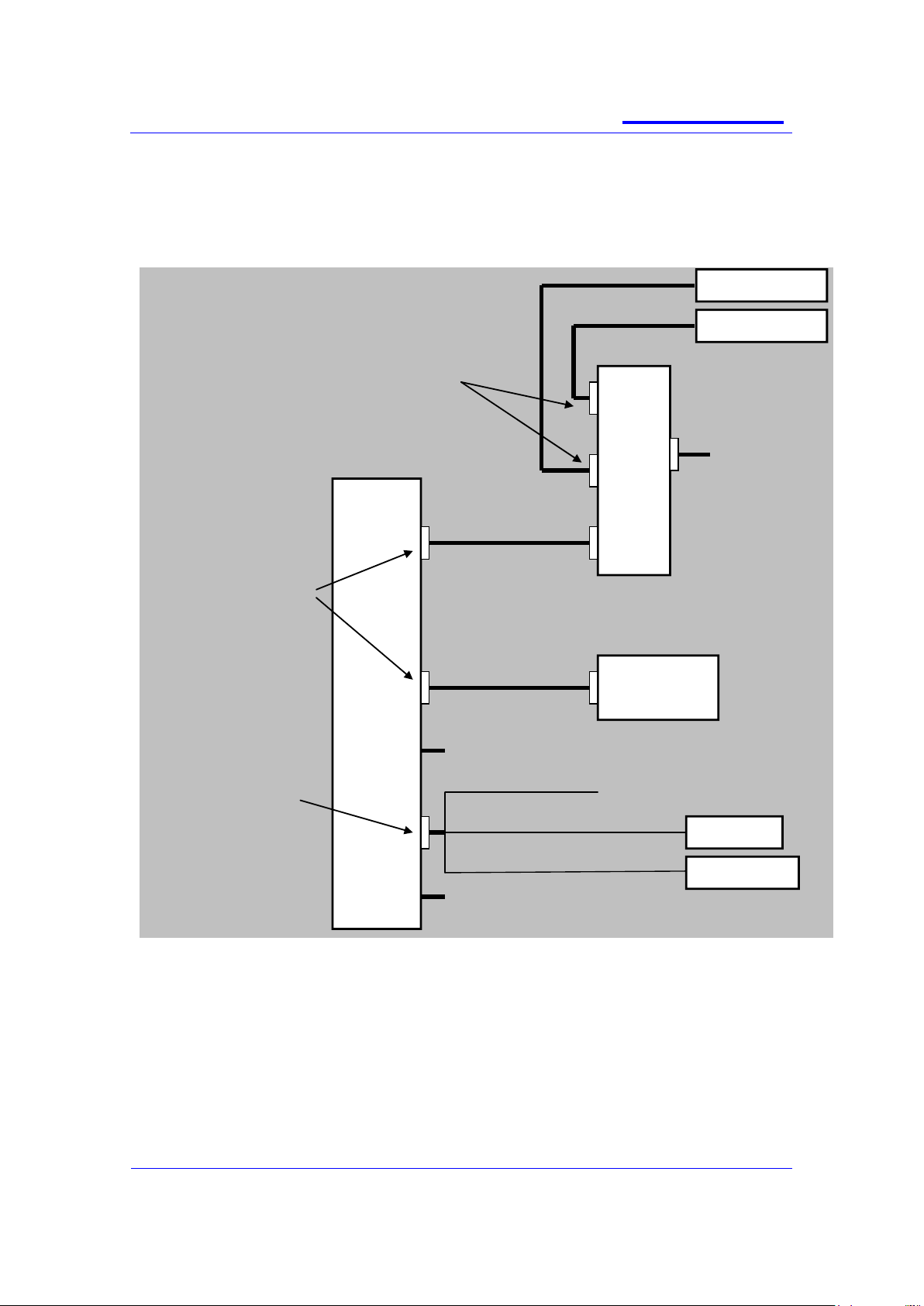
EXAMPLE INTERCONNECT BLOCK DIAGRAM
The diagram shows just one of many possible solutions and highlights the flexibility of the
Sepura product.
 Loading...