

Page 1
Smart-Reach™ Base
Installation and Quick Start Guide
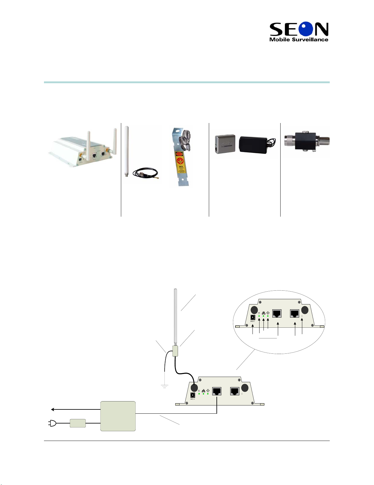
Package Contents (typical)
The contents of a typical installation package are shown below. The actual contents of your installation
package may vary. The installation package include 3 ft Ethernet (CAT5e) cable and mounting hardware.
Smart-Reach Base (single or
dual radio)
Omni-directional antenna with
mounting bracket and 6 ft coaxial
cable
PoE (Power over Ethernet)
injector and AC adapter
Antenna lightning
(surge) protector,
N-Male to
N-Female
Additional components required:
• Ethernet cable to connect the PoE injector to
ETHERNET Port 1 on the Smart-Reach Base. Purchase the
length required for your installation.
• 12 AWG stranded wire to connect the ground terminal on the surge protector to a pipe in the ground.
Installation
In a typical installation, the Smart-Reach Base, single radio or dual radio, is mounted indoors.
Antenna
RADIO 1
12
802.3af
Wireless
Ethernet
Ethernet por ts Reset button
Status lights
ETHERNET
AUX
Connect to
Eart h Ground
Surge pr otect or
Power
connector
MAIN
5 VDC
Power
Ether net to
Int r anet / Com puter
700-0068
R001
Pow er Ov er E thernet
Injector
Ethernet
Et hernet + DC
48V D C
Ethernet c able
(additional
component)
Smart -Reach™ Bas e
MAIN
5 VDC
802.3af
RADIO 1
12
ETHERNET
AUX
1
Page 2
Quick Start Guide
Installing the Antenna
The Smart-Reach Base can have a single or dual radio with two antennas for diversity. Each radio has two
antenna connections: Main and Aux. In a typical installation, only the Main antenna connection on each
radio is used. The antenna is supplied with a mounting bracket and a lightning protector. The antenna
connectors are reverse-polarity
SMA jacks. Antenna or cable connectors must use RP-SMA plugs.
WARNING
Check with the local electrical code requirements for the proper installation and grounding of the lighting protector.
Seon Design Inc. is not responsible for improper installation of the lightning protector and does not provide protection
against lightning strikes.
1 Secure the mounting bracket to the desired location.
2 Insert the antenna into the bracket and secure with the supplied hardware.
3 Attach the lightning protector.
4 Use 12 AWG stranded wire to connect the ground terminal on the lighting connector to a pipe in the
ground.
5 Connect the SMA-RP connector on the coaxial cable to the
MAIN antenna connector on the Smart-
Reach.
6 Connect the other end of the cable to the lighting protector to a torque of 6–10 in lbs (0.68–1.13 Nm).
Do not overtighten.
Installing the Smart-Reach Base
CAUTION
Shielded Ethernet cables must be used for all connections.
Mount the Smart-Reach Base in a secure and dry location.
• Wall or ceiling: ensure the mounting surface can support a minimum of 2 pounds (0.9 kg) for the
Smart-Reach Base and the fasteners. Allow extra weight for cables.
• Inside a plenum: plenum-rated cables and attachment hardware must be used. Only the Smart-Reach
Base and appropriate cabling can be located in the plenum.
CAUTION
Power supplies and PoE (power over Ethernet) injectors cannot be installed inside a plenum.
1 Use the Ethernet CAT5e cable to connect
connector on the PoE injector.
ETHERNET Port 1 on the Smart-Reach Base to Ethernet + DC
2 Connect the PoE Ethernet cable to a properly configured computer/network.
2
700-0068
R001
Page 3
Quick Start Guide
WARNING: Surge Protection and Grounding
If you plan on connecting an outdoor antenna to the Smart-Reach Base, make sure that proper lightning surge protection
and grounding precautions are taken according to local electrical code. Failure to do so may result in personal injury,
fire, equipment damage, or a voided warranty .
Testing the Wireless Network
By default, the Smart-Reach Base is configured with the static IP address 172.24.1.1. Note: Your network
configuration may vary.
1 Enable your computer’s wireless network interface, and verify that it is set with the static IP address
172.24.1.2. to 172.24.1.254.
In Windows XP, use Control Panel > Network Connections > Local Area Connection > Properties
> Internet Protocol (TCP/IP) > Properties.
2 Connect to the wireless network. From the Windows XP Start menu, select Settings > Network
Connections > Wireless Network Connections. The list of available wireless networks appears.
Select Seon Network (default) and then Connect.
3 Confirm that you can ping the Access point from the host computer.
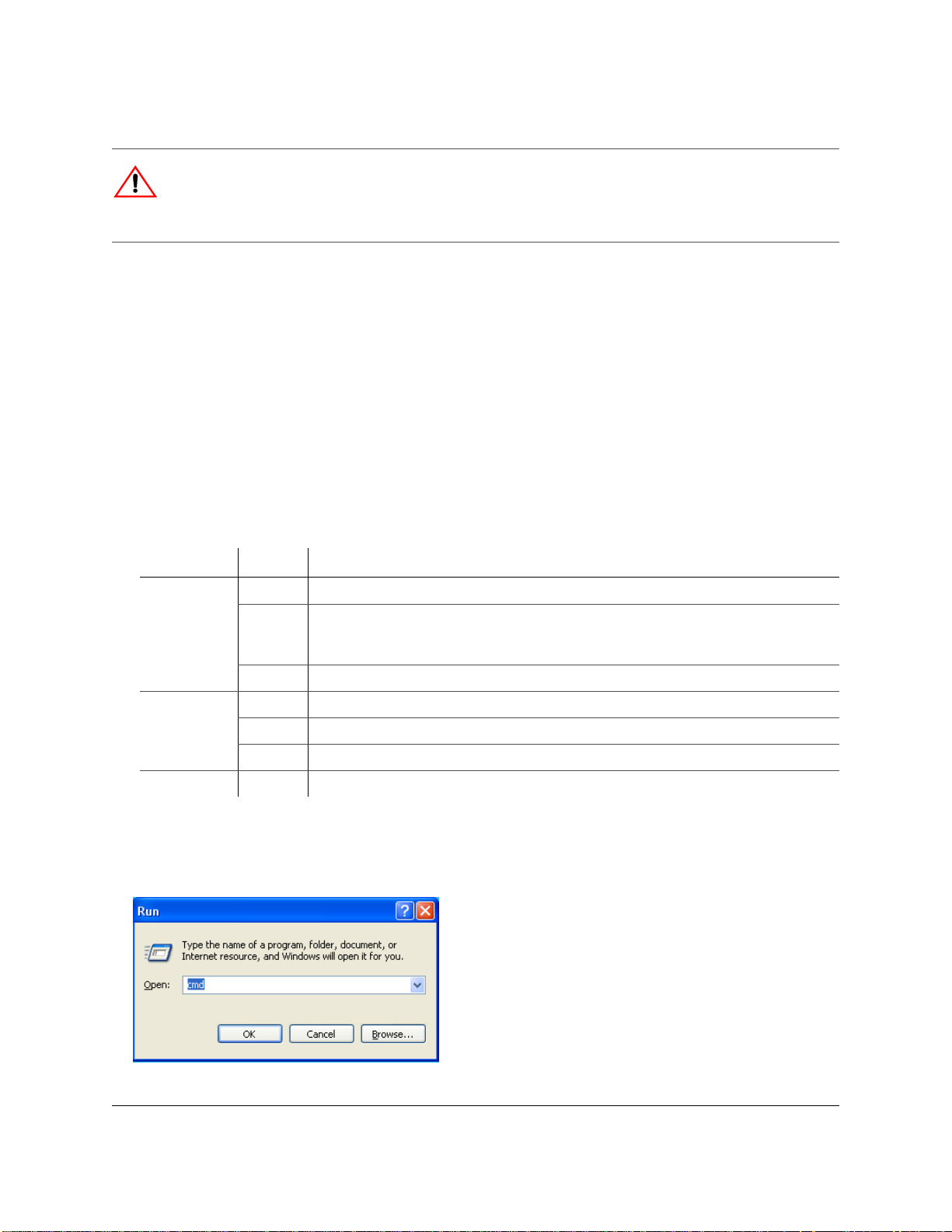
The status lights provide the following information:
Status Light State Description
Power On Smart-Reach Base is fully operational.
Flashing Smart-Reach Base is starting up. If the power light continues to flash after several minutes,
the firmware has failed to load. Reset or power cycle the Smart-Reach Base. If this condition
persists, contact Seon Customer Service at [email protected].
Off Smart-Reach Base has no power.
Ethernet On Illuminates for a short time when the link is established.
Flashing Ethernet port is transmitting or receiving data.
Off Ethernet port is not connected or there is no activity.
Wireless Flashing Wireless port is transmit ting or receiving data.
Using the Ping Command
1 On the Start menu, click Run.
700-0068
R001
3
Page 4
Quick Start Guide
2 Type cmd and click OK.
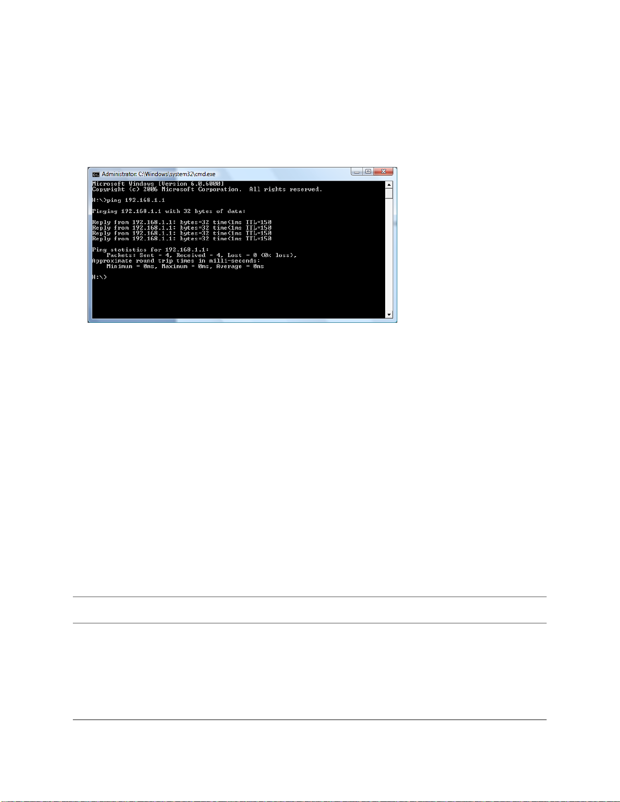
3 In the command line, type ping xxx.xxx.xxx.xxx (the IP address of the machine you wish to
contact).
4 If you successfully ping the machine, you will get a reply as shown.
5 If your ping is not successful, your requests will time out or you will receive a notice that the recipient
could not be contacted.
Configuration
The Smart-Reach Base has pre-configured Seon default settings. To make minor changes to configuration,
read through this section. The Smart-Reach Base is managed via its Web-based management software
using Microsoft® Internet Explorer® 7.0 or Mozilla Firefox®2.0 or later versions.
Configuring the Network Settings of your Computer
1 Use the Ethernet cable to connect the LAN port on your computer to the Ethernet port on the PoE
injector.
2 Configure your computer to use a static IP address in the range 172.24.1.2 to 172.24.1.254. The subnet
mask of 255.255.255.0 is entered automatically. Set the default gateway to 172.24.1.1 and the DNS
server to 192.168.1.1.
In Windows XP, use Control Panel > Network Connections > Local Area Connection > Properties
> Internet Protocol (TCP/IP) > Properties.
3 Disable any wireless connection.
Important:
contact Customer Service.
To perf orm any additional configuration, assign an IP address, or to reset the Sm art-Reach Base to factory defaults,
4
700-0068
R001
Page 5

Quick Start Guide
FCC Information to the User
This equipment has been tested and found to comply with the limits for a digital device, pursuant to Part 15
of the FCC rules. These limits are designed to provide reasonable protection against harmful interference
in a residential installation. This equipment generates, uses, and can radiate radio frequency energy. If not
installed and used in accordance with the instructions, it may cause harmful interference to radio
communications. However, there is no guarantee that interference will not occur in a particular installation.
If this equipment causes harmful interference to radio or television reception, which can be determined by
turning the equipment off and on, the user is encouraged to try to correct the interference by one or more of
the following measures:
• Reorient or relocate the receiving antenna.
• Increase the separation between the equipment and the receiver.
• Connect the equipment into an outlet on a circuit different from that to which the receiver is connected.
• Consult the dealer or an experience radio/TV technician for help.
Customer Service Contact Information
Toll free telephone 1-877-630-7366 or telephone 604-941-0880
Email: [email protected]
©February 2009. Printed in Canada. All rights reserved. Seon Design Inc. www.seon.com
700-0068
R001
5
 Loading...