

Page 1

Explorer™ EX8 Plus Mobile
Digital Video Recording
(DVR) System
Installation and User’s Guide
Manual Type
*700-0048*
Document part number 700-0048 R003
Page 2

Page 3

Seon Design® Inc.
Seon Design Inc. is a specialist in the design and manufacture of video surveillance systems for mobile applications. Seon has
been the preferred solutions provider for the pupil transportation industry since 1999. Today, we are proud that our success in
this area has made us the leading manufacturer of mobile video surveillance systems in North America.
Contact Information
Seon Design Inc.
Unit 111, 3B Burbidge Street
Coquitlam, BC
Canada V3K 7B2
Telephone 604.941.0880
Toll Free Telephone 1.877.630.7366
Fax 604.941.0870
Toll Free Fax 1.866.664.3677
Email [email protected]
Web site www .seon.com
Seon Design Inc. Trademarks
Seon Design Inc. holds the following trademarks:
Explorer™ is a registered trademark of Seon Design Inc.
“Seon Design” is a registered trademark of Seon Design Inc.
The Seon logo ( ) is a registered trademark of Seon Design Inc.
In this User Manual there are references to trademarks, registered trademarks, and product names not owned by Seon Design
Inc. that are the property of their respective owners. They are used in this User Manual for identification purposes only.
User Manual Revision
This is the July 2007 revision for this User Manual and is copyright, July 2007 of Seon Design Inc. All rights reserved.
Exclusion of Liability
SEON DESIGN INC.:
(a)
MAKES NO REPRESENTATION, WARRANTY, GUARANTEE OR COVENANT, EXPRESS OR IMPLIED, AS TO THE ACCURACY,
SUFFICIENCY OR SUITABILITY OF ANY TECHNICAL OR OTHER INFORMATION PROVIDED IN THIS USER MANUAL OR ANY OTHER
USER OR OTHER MANUAL OR OTHER DOCUMENTATION PROVIDED BY SEON DESIGN INC. WITH RESPECT TO THE PRODUCT(S)
DESCRIBED HEREIN, INCLUDING WITHOUT LIMITATION ANY DESCRIPTION OF GOODS OR SERVICES, SPECIFICATIONS, MODELS,
DRAWINGS, OR DIAGRAMS.
(b)
DOES NOT ASSUME AND SHALL NOT BE SUBJECT TO AND DISCLAIMS ANY AND ALL RESPONSIBILITY AND/OR LIABILITY FOR
LOSSES, DAMAGES, COSTS OR EXPENSES ARISING OUT OF BREACH OF CONTRACT OR OF WARRANTY, TORT (INCLUDING
NEGLIGENCE AND STRICT LIABILITY) OR OTHERWISE, WHETHER SPECIAL, DIRECT, INDIRECT, CONSEQUENTIAL, INCIDENTAL,
SPECIAL OR CONTINGENT, WHICH MIGHT ARISE OUT OF THE USE OF SUCH INFORMATION. THE USE OF ANY SUCH INFORMATION
WILL BE ENTIRELY AT THE USER’S RISK; AND
(c) EXPRESSLY DISCLOSES THAT IF THIS MANUAL IS WRITTEN IN ANY LANGUAGE OTHER THAN ENGLISH, THAT ALTHOUGH
SEON DESIGN INC. HAS USED REASONABLE CARE TO MAINTAIN THE ACCURACY OF THE TRANSLATION FROM THE ENGLISH
LANGUAGE, THE ACCURACY OF SUCH TRANSLATION IS NOT GUARANTEED OR WARRANTED BY SEON DESIGN INC. PLEASE REFER
TO THE ENGLISH LANGUAGE VERSION OF THIS USER MANUAL FOR APPROVED SEON CONTENT. THE ENGLISH LANGUAGE
VERSION IS AVAILABLE UPON REQUEST FROM THE SEON CUSTOMER SERVICE DEPARTMENT.
Please refer to the Seon Design Inc. Product Warranty applicable to the Product(s) described in this User Manual which
exclusively sets forth Seon Design Inc.’s entire liability arising from or in connection with such product(s) and their use and
the exclusive remedies available for purchasers and users thereof.
Document Part Number
This User Manual is valid for Seon Design Inc. Document Part Number 700-0048.
PRINTED IN CANADA
Page 4

Page 5
Who This Guide is For
The Installation and User’s Guide is intended for anyone who needs to install and
operate the Explorer EX8 Plus Mobile Digital Video Recording (DVR) System
(EX8 Plus System).
This Guide provides information and procedures for installing, configuring,
operating, maintaining, and troubleshooting the EX8 Plus System.
Conventions Used
CAUTION
Cautions identify conditions or practices that could result in damage to the unit or to other
equipment.
Important:
not as serious as a Caution.
These notes describe things which are important for you to know, but they
Abbreviations and Acronyms
Acronym Definition
DVR Digital video recorder
FPS Frames per second
GPS Global Positioning System
HD Hard drive
IPS Images per second
IR Infrared
LAN Local area network
MPEG Moving Picture Experts Group
RA Return Authorization
TCM Transmission Control Module
UTC Universal Time Coordinated
700-0048 R003
Page 6

Related Documentation
Refer to the following related documentation.
SA Series Wedge Camera Setup Guide Document part number 700-0004
SJ Series Dome Camera Setup Guide Document part number 700-0049
HD Reader User’s Guide Document part number 700-0036
TR-INR Inertia Sensor Installation and
User Guide
Finding Information Online
You can find information about Seon Design Inc,. as well as its products and
services, by visiting www.seon.com.
Document part number 700-0041
ii 700-0048 R003
Page 7

Contents
Chapter 1
1.1. EX8 Plus System- - - - - - - - - - - - - - - - - - - - - - - - - - - - - - - - - - - - - - - - - - - - - - - - - - - - 1–2
1.2. EX8 Plus System Product Features- - - - - - - - - - - - - - - - - - - - - - - - - - - - - - - - - - - - - - - - 1–2
1.3. EX8 Plus DVR - - - - - - - - - - - - - - - - - - - - - - - - - - - - - - - - - - - - - - - - - - - - - - - - - - - - - 1–3
1.3.1. DVR Front Panel Features - - - - - - - - - - - - - - - - - - - - - - - - - - - - - - - - - - - - - - - - - 1–3
1.3.2. DVR Buttons - - - - - - - - - - - - - - - - - - - - - - - - - - - - - - - - - - - - - - - - - - - - - - - - - - 1–5
1.3.3. DVR Back Panel Features - - - - - - - - - - - - - - - - - - - - - - - - - - - - - - - - - - - - - - - - - - 1–7
1.4. Lock Box - - - - - - - - - - - - - - - - - - - - - - - - - - - - - - - - - - - - - - - - - - - - - - - - - - - - - - - - - 1–8
1.5. Cables and Harnesses- - - - - - - - - - - - - - - - - - - - - - - - - - - - - - - - - - - - - - - - - - - - - - - - - 1–8
Chapter 2
2.1. Installing the EX8 Plus DVR and Lock Box - - - - - - - - - - - - - - - - - - - - - - - - - - - - - - - - - 2–2
2.2. Step 1: Installing the Lock Box - - - - - - - - - - - - - - - - - - - - - - - - - - - - - - - - - - - - - - - - - -2–3
2.2.1. Horizontal Installation - - - - - - - - - - - - - - - - - - - - - - - - - - - - - - - - - - - - - - - - - - - - 2–3
2.2.2. Vertical Installation - - - - - - - - - - - - - - - - - - - - - - - - - - - - - - - - - - - - - - - - - - - - - - 2–4
2.3. Step 2: Installing the DVR in the Lock Box- - - - - - - - - - - - - - - - - - - - - - - - - - - - - - - - - - 2–5
2.4. Step 3: Installing the Cameras - - - - - - - - - - - - - - - - - - - - - - - - - - - - - - - - - - - - - - - - - - - 2–5
2.4.1. Checking the Camera Cable Connections - - - - - - - - - - - - - - - - - - - - - - - - - - - - - - - 2–5
2.5. Step 4: Connecting the DVR - - - - - - - - - - - - - - - - - - - - - - - - - - - - - - - - - - - - - - - - - - - - 2–7
2.5.1. Connecting to the DVR Back Panel - - - - - - - - - - - - - - - - - - - - - - - - - - - - - - - - - - - 2–7
2.6. Step 5: Connecting the Ignition Harness, Power Harness, Fuses and Fuse Holders - - - - - - - - 2–9
2.6.1. Connecting the Ignition Harness - - - - - - - - - - - - - - - - - - - - - - - - - - - - - - - - - - - - - 2–9
2.6.2. Connecting the Power Harness to the Battery - - - - - - - - - - - - - - - - - - - - - - - - - - - - 2–10
2.7. Step 6: Installing the Smart-Link™ Module- - - - - - - - - - - - - - - - - - - - - - - - - - - - - - - - - 2–10
2.7.1. Connecting the Signal Harness - - - - - - - - - - - - - - - - - - - - - - - - - - - - - - - - - - - - - 2–12
2.7.2. Connecting the Speed Cable - - - - - - - - - - - - - - - - - - - - - - - - - - - - - - - - - - - - - - - 2–13
2.8. Step 7: Installing the GPS Receiver - - - - - - - - - - - - - - - - - - - - - - - - - - - - - - - - - - - - - - 2–14
2.9. Step 8: Installing the Driver’s Indicator Panel - - - - - - - - - - - - - - - - - - - - - - - - - - - - - - - 2–14
2.9.1 Status of the Driver’s Indicator Panel - - - - - - - - - - - - - - - - - - - - - - - - - - - - - - - - - - 2–15
2.10. Step 9: Hardware Installation Final Checklist- - - - - - - - - - - - - - - - - - - - - - - - - - - - - - - 2–15
2.11. TR-INR Inertia Sensor - - - - - - - - - - - - - - - - - - - - - - - - - - - - - - - - - - - - - - - - - - - - - - 2–16
2.12. CAN Network- - - - - - - - - - - - - - - - - - - - - - - - - - - - - - - - - - - - - - - - - - - - - - - - - - - - 2–16
2.13. EZN Decoy System - - - - - - - - - - - - - - - - - - - - - - - - - - - - - - - - - - - - - - - - - - - - - - - - 2–16
2.14. Wireless Network - - - - - - - - - - - - - - - - - - - - - - - - - - - - - - - - - - - - - - - - - - - - - - - - - 2–16
Introduction
Installation
700-0048 R003 iii
Page 8

Contents
Chapter 3
3.1. Configuring the DVR - - - - - - - - - - - - - - - - - - - - - - - - - - - - - - - - - - - - - - - - - - - - - - - - 3–2
3.2. EX8 Plus DVR Main Menu - - - - - - - - - - - - - - - - - - - - - - - - - - - - - - - - - - - - - - - - - - - - 3–4
3.2.1. Software Version - - - - - - - - - - - - - - - - - - - - - - - - - - - - - - - - - - - - - - - - - - - - - - - 3–5
3.2.2. Using the Time/Date Menu - - - - - - - - - - - - - - - - - - - - - - - - - - - - - - - - - - - - - - - - 3–5
3.2.3. Using the Titles/Display Menu - - - - - - - - - - - - - - - - - - - - - - - - - - - - - - - - - - - - - - 3–8
3.2.4. Using the Record Menu - - - - - - - - - - - - - - - - - - - - - - - - - - - - - - - - - - - - - - - - - - -3–10
3.2.5. Using the Alarms Menu - - - - - - - - - - - - - - - - - - - - - - - - - - - - - - - - - - - - - - - - - - -3–15
3.2.6. Using the Timers Menu - - - - - - - - - - - - - - - - - - - - - - - - - - - - - - - - - - - - - - - - - - -3–20
3.2.7. Using the Signals Menu - - - - - - - - - - - - - - - - - - - - - - - - - - - - - - - - - - - - - - - - - - -3–22
3.2.8. Using the GPS/Speed Menu - - - - - - - - - - - - - - - - - - - - - - - - - - - - - - - - - - - - - - - -3–24
3.2.9. Using the Network Menu - - - - - - - - - - - - - - - - - - - - - - - - - - - - - - - - - - - - - - - - - -3–27
3.2.10. Using the System Menu - - - - - - - - - - - - - - - - - - - - - - - - - - - - - - - - - - - - - - - - - -3–29
3.2.11. Updating the Software Program - - - - - - - - - - - - - - - - - - - - - - - - - - - - - - - - - - - -3–32
Chapter 4
4.1. Operating and Monitoring the DVR- - - - - - - - - - - - - - - - - - - - - - - - - - - - - - - - - - - - - - - 4–2
4.1.1 Using the DVR buttons - - - - - - - - - - - - - - - - - - - - - - - - - - - - - - - - - - - - - - - - - - - 4–2
4.2. Viewing Recorded Video- - - - - - - - - - - - - - - - - - - - - - - - - - - - - - - - - - - - - - - - - - - - - - 4–5
4.2.1. Using the SHUTTLE Wheel during Playback - - - - - - - - - - - - - - - - - - - - - - - - - - - - 4–5
4.2.2. Using the ZOOM Button and JOG Wheel to Adjust the Display - - - - - - - - - - - - - - - - 4–5
4.3. Replacing the Hard Drive - - - - - - - - - - - - - - - - - - - - - - - - - - - - - - - - - - - - - - - - - - - - - 4–6
4.4. Downloading Video to a PC- - - - - - - - - - - - - - - - - - - - - - - - - - - - - - - - - - - - - - - - - - - - 4–6
4.5. Extended Operational Functions - - - - - - - - - - - - - - - - - - - - - - - - - - - - - - - - - - - - - - - - - 4–6
4.5.1. Reading CAN messages - - - - - - - - - - - - - - - - - - - - - - - - - - - - - - - - - - - - - - - - - - 4–6
4.5.2. Using the ONE-TOUCH Download option - - - - - - - - - - - - - - - - - - - - - - - - - - - - - - 4–7
4.5.3. Using the Search function - - - - - - - - - - - - - - - - - - - - - - - - - - - - - - - - - - - - - - - - - 4–7
4.5.4. Using the Copy Menu - - - - - - - - - - - - - - - - - - - - - - - - - - - - - - - - - - - - - - - - - - - -4–11
4.5.5. Turning the Buzzer Off - - - - - - - - - - - - - - - - - - - - - - - - - - - - - - - - - - - - - - - - - - -4–13
4.5.6. Using the LOCK Button - - - - - - - - - - - - - - - - - - - - - - - - - - - - - - - - - - - - - - - - - -4–13
4.6. Voltage Display - - - - - - - - - - - - - - - - - - - - - - - - - - - - - - - - - - - - - - - - - - - - - - - - - - - -4–13
4.7. Low Voltage and Low/High Temp Indicator- - - - - - - - - - - - - - - - - - - - - - - - - - - - - - - - -4–13
4.8. Advanced Smart-Temp - - - - - - - - - - - - - - - - - - - - - - - - - - - - - - - - - - - - - - - - - - - - - - -4–14
Configuring the DVR
Operating the DVR
Chapter 5
5.1. Maintenance - - - - - - - - - - - - - - - - - - - - - - - - - - - - - - - - - - - - - - - - - - - - - - - - - - - - - - 5–2
5.1.1. Cleaning the Lock Box - - - - - - - - - - - - - - - - - - - - - - - - - - - - - - - - - - - - - - - - - - - 5–2
5.1.2. Cleaning the Camera and Window - - - - - - - - - - - - - - - - - - - - - - - - - - - - - - - - - - - 5–2
5.1.3. Replacing the Fan Filter - - - - - - - - - - - - - - - - - - - - - - - - - - - - - - - - - - - - - - - - - - - 5–2
5.2. Returning Product for Service- - - - - - - - - - - - - - - - - - - - - - - - - - - - - - - - - - - - - - - - - - - 5–3
iv 700-0048 R003
Maintenance and Returning Product for Service
Page 9

Contents
Chapter 6
6.1. Troubleshooting the EX8 Plus System - - - - - - - - - - - - - - - - - - - - - - - - - - - - - - - - - - - - - 6–2
Appendix A
A.1. EX8 Plus DVR- - - - - - - - - - - - - - - - - - - - - - - - - - - - - - - - - - - - - - - - - - - - - - - - - - - - -A–2
A.2. DVR Functional Features- - - - - - - - - - - - - - - - - - - - - - - - - - - - - - - - - - - - - - - - - - - - - -A–3
A.3. Additional Features of the EX8 Plus DVR - - - - - - - - - - - - - - - - - - - - - - - - - - - - - - - - - -A–3
A.4. Lock Box - - - - - - - - - - - - - - - - - - - - - - - - - - - - - - - - - - - - - - - - - - - - - - - - - - - - - - - -A–4
A.5. Smart-Link™ Module - - - - - - - - - - - - - - - - - - - - - - - - - - - - - - - - - - - - - - - - - - - - - - - -A–4
Troubleshooting
Specifications
SEON DESIGN™ INC. PRODUCT WARRANTY
DISCLAIMER - - - - - - - - - - - - - - - - - - - - - - - - - - - - - - - - - - - - - - - - - - - - - - - - - - - - W–1
700-0048 R003 v
Page 10

vi
Page 11

Tables
Table 1-1 Front panel features- - - - - - - - - - - - - - - - - - - - - - - - - - - - - - - - - - - - - - - - - - - - - - - 1–3
Table 1-2 Description of DVR buttons - - - - - - - - - - - - - - - - - - - - - - - - - - - - - - - - - - - - - - - - - 1–5
Table 2-1 Camera cable wiring - - - - - - - - - - - - - - - - - - - - - - - - - - - - - - - - - - - - - - - - - - - - - - 2–6
Table 2-2 Signal harness wiring- - - - - - - - - - - - - - - - - - - - - - - - - - - - - - - - - - - - - - - - - - - - - 2–12
Table 2-3 Speed cable wiring - - - - - - - - - - - - - - - - - - - - - - - - - - - - - - - - - - - - - - - - - - - - - - 2–13
Table 2-4 Driver’s indicator panel status- - - - - - - - - - - - - - - - - - - - - - - - - - - - - - - - - - - - - - - 2–15
Table 3-1 On-screen display information - - - - - - - - - - - - - - - - - - - - - - - - - - - - - - - - - - - - - - - 3–2
Table 3-2 Time/Date configuration items - - - - - - - - - - - - - - - - - - - - - - - - - - - - - - - - - - - - - - - 3–6
Table 3-3 Titles/Display configuration items - - - - - - - - - - - - - - - - - - - - - - - - - - - - - - - - - - - - - 3–9
Table 3-4 Record configuration items- - - - - - - - - - - - - - - - - - - - - - - - - - - - - - - - - - - - - - - - - 3–11
Table 3-5 Picture quality settings- - - - - - - - - - - - - - - - - - - - - - - - - - - - - - - - - - - - - - - - - - - - 3–13
Table 3-6 Estimated recording time in hours with 80 GB hard drive - - - - - - - - - - - - - - - - - - - - 3–14
Table 3-7 Estimated recording time in hours with 500 GB hard drive - - - - - - - - - - - - - - - - - - - 3–14
Table 3-8 Estimated recording time in hours with 750 GB hard drive - - - - - - - - - - - - - - - - - - - 3–15
Table 3-9 Alarm configuration items - - - - - - - - - - - - - - - - - - - - - - - - - - - - - - - - - - - - - - - - - 3–17
Table 3-10 Alarm 1 settings configuration items - - - - - - - - - - - - - - - - - - - - - - - - - - - - - - - - - - 3–18
Table 3-11 Timers configuration items- - - - - - - - - - - - - - - - - - - - - - - - - - - - - - - - - - - - - - - - - 3–21
Table 3-12 Signal configuration items - - - - - - - - - - - - - - - - - - - - - - - - - - - - - - - - - - - - - - - - - 3–23
Table 3-13 GPS/SPEED configuration items- - - - - - - - - - - - - - - - - - - - - - - - - - - - - - - - - - - - - 3–25
Table 3-14 Network configuration items- - - - - - - - - - - - - - - - - - - - - - - - - - - - - - - - - - - - - - - - 3–28
Table 3-15 System configuration items- - - - - - - - - - - - - - - - - - - - - - - - - - - - - - - - - - - - - - - - - 3–30
Table 4-1 Using the DVR buttons - - - - - - - - - - - - - - - - - - - - - - - - - - - - - - - - - - - - - - - - - - - - 4–3
Table 4-2 Event types - - - - - - - - - - - - - - - - - - - - - - - - - - - - - - - - - - - - - - - - - - - - - - - - - - - - 4–9
Table 4-3 Search menu configuration items- - - - - - - - - - - - - - - - - - - - - - - - - - - - - - - - - - - - - 4–10
Table 4-4 Copy menu configuration items- - - - - - - - - - - - - - - - - - - - - - - - - - - - - - - - - - - - - - 4–12
Table 4-5 LOW VOLTAGE/LOW/HIGH TEMP indicator - - - - - - - - - - - - - - - - - - - - - - - - - - 4–14
Table 4-6 Advanced Smart-Temp features- - - - - - - - - - - - - - - - - - - - - - - - - - - - - - - - - - - - - - 4–14
700-0048 R003 vii
Page 12

viii
Page 13

Figures
Figure 1-1 EX8 Plus DVR front panel - - - - - - - - - - - - - - - - - - - - - - - - - - - - - - - - - - - - - - - - - - 1–3
Figure 1-2 Back panel- - - - - - - - - - - - - - - - - - - - - - - - - - - - - - - - - - - - - - - - - - - - - - - - - - - - - 1–7
Figure 2-1 Lock box horizontal installation - - - - - - - - - - - - - - - - - - - - - - - - - - - - - - - - - - - - - - 2–4
Figure 2-2 Lock box vertical installation - - - - - - - - - - - - - - - - - - - - - - - - - - - - - - - - - - - - - - - - 2–5
Figure 2-3 Terminal blocks in the camera- - - - - - - - - - - - - - - - - - - - - - - - - - - - - - - - - - - - - - - - 2–6
Figure 2-4 Back panel connections - - - - - - - - - - - - - - - - - - - - - - - - - - - - - - - - - - - - - - - - - - - - 2–7
Figure 2-5 Smart-Link-to-DVR connection harness - - - - - - - - - - - - - - - - - - - - - - - - - - - - - - - - - 2–8
Figure 2-6 Power harness- - - - - - - - - - - - - - - - - - - - - - - - - - - - - - - - - - - - - - - - - - - - - - - - - - - 2–8
Figure 2-7 Ignition harness wires - - - - - - - - - - - - - - - - - - - - - - - - - - - - - - - - - - - - - - - - - - - - - 2–9
Figure 2-8 Smart-Link module - - - - - - - - - - - - - - - - - - - - - - - - - - - - - - - - - - - - - - - - - - - - - - 2–11
Figure 2-9 3-foot Smart-Link signal harness - - - - - - - - - - - - - - - - - - - - - - - - - - - - - - - - - - - - - 2–12
Figure 2-10 20-foot Smart-Link speed cable- - - - - - - - - - - - - - - - - - - - - - - - - - - - - - - - - - - - - - 2–13
Figure 2-11 Driver’s indicator panel - - - - - - - - - - - - - - - - - - - - - - - - - - - - - - - - - - - - - - - - - - - 2–14
Figure 3-1 On-screen display during live viewing and recording - - - - - - - - - - - - - - - - - - - - - - - - 3–2
Figure 3-2 Main menu- - - - - - - - - - - - - - - - - - - - - - - - - - - - - - - - - - - - - - - - - - - - - - - - - - - - - 3–4
Figure 3-3 Time/Date menu - - - - - - - - - - - - - - - - - - - - - - - - - - - - - - - - - - - - - - - - - - - - - - - - - 3–5
Figure 3-4 Titles/Display menu - - - - - - - - - - - - - - - - - - - - - - - - - - - - - - - - - - - - - - - - - - - - - - 3–8
Figure 3-5 Record menu - - - - - - - - - - - - - - - - - - - - - - - - - - - - - - - - - - - - - - - - - - - - - - - - - - 3–10
Figure 3-6 Alarms menu - - - - - - - - - - - - - - - - - - - - - - - - - - - - - - - - - - - - - - - - - - - - - - - - - - 3–16
Figure 3-7 Alarm settings sub-menu - - - - - - - - - - - - - - - - - - - - - - - - - - - - - - - - - - - - - - - - - - 3–17
Figure 3-8 Timers menu - - - - - - - - - - - - - - - - - - - - - - - - - - - - - - - - - - - - - - - - - - - - - - - - - - 3–20
Figure 3-9 Signals menu - - - - - - - - - - - - - - - - - - - - - - - - - - - - - - - - - - - - - - - - - - - - - - - - - - 3–22
Figure 3-10 GPS/Speed menu - - - - - - - - - - - - - - - - - - - - - - - - - - - - - - - - - - - - - - - - - - - - - - - 3–24
Figure 3-11 Network menu - - - - - - - - - - - - - - - - - - - - - - - - - - - - - - - - - - - - - - - - - - - - - - - - - 3–27
Figure 3-12 System menu - - - - - - - - - - - - - - - - - - - - - - - - - - - - - - - - - - - - - - - - - - - - - - - - - - 3–29
Figure 3-13 Export defaults popup menu - - - - - - - - - - - - - - - - - - - - - - - - - - - - - - - - - - - - - - - - 3–33
Figure 3-14 Program update popup menu- - - - - - - - - - - - - - - - - - - - - - - - - - - - - - - - - - - - - - - - 3–33
Figure 3-15 Load defaults popup menu - - - - - - - - - - - - - - - - - - - - - - - - - - - - - - - - - - - - - - - - - 3–34
Figure 3-16 Import defaults popup menu - - - - - - - - - - - - - - - - - - - - - - - - - - - - - - - - - - - - - - - - 3–35
Figure 3-17 Format hard-drive popup menu - - - - - - - - - - - - - - - - - - - - - - - - - - - - - - - - - - - - - - 3–36
Figure 4-1 Front panel DVR buttons - - - - - - - - - - - - - - - - - - - - - - - - - - - - - - - - - - - - - - - - - - - 4–2
Figure 4-2 Search menu- - - - - - - - - - - - - - - - - - - - - - - - - - - - - - - - - - - - - - - - - - - - - - - - - - - - 4–8
Figure 4-3 Copy menu - - - - - - - - - - - - - - - - - - - - - - - - - - - - - - - - - - - - - - - - - - - - - - - - - - - 4–11
Figure 5-1 Replacing the fan filter- - - - - - - - - - - - - - - - - - - - - - - - - - - - - - - - - - - - - - - - - - - - - 5–2
700-0048 R003 ix
Page 14

x
Page 15

CHAPTER 1
Introduction
This chapter describes the product features and components of the Explorer
EX8 Plus Mobile Digital Video Recording (DVR) System
(EX8 Plus System).
Page 16

Introduction
1.1. EX8 Plus System
The EX8 Plus System consists of the following components:
• EX8 Plus DVR
• Lock box
• Cameras
•Hard drive
• Driver’s indicator panel (video recording label optional)
• GPS (Global Positioning System) (if purchased)
• Smart-Link™ module
• Cables and harnesses for power, ignition input, Smart-Link interface, alarms
and signals
1.2. EX8 Plus System Product Features
The EX8 Plus System has been designed using extremely reliable and easy-to-use
technology, including:
• Rugged digital video recorder
• MPEG-4 compression
• Eight video channels and two audio channels
• Selectable image quality, resolution, and recording rate
• Replaceable/upgradeable hard drives to extend recording times
• Downloadable images and video using USB memory devices
• On-screen display of time, date, vehicle identification, and system voltage
• Integrated Ethernet network connection for LAN interfaces or other high-speed
expansion devices
• Smart-Start™ to prevent potential damage from voltage spikes and drops
during vehicle start-up
• Advanced Smart-Te mp™ and built-in heater to ensure safe operation over a
wide temperature range
• Smart-Link™ module for signal interfaces, including:
• GPS data and vehicle speed
• Ten different input signals, including CAN signals
• Driver’s indicator panel
• 4 different event alarm inputs
• Configurable software
• Repeat recording, user selectable
• Variable record delay-on and record delay-off recording, selectable up to 60
minutes
• Twelve daily/weekly timers to set DVR recording time
• Temporary power for setup and playback
• Front panel video output jack for setup and playback
ON or OFF
1–2 700-0048 R003
Page 17
1.3. EX8 Plus DVR
1.3.1. DVR Front Panel Features
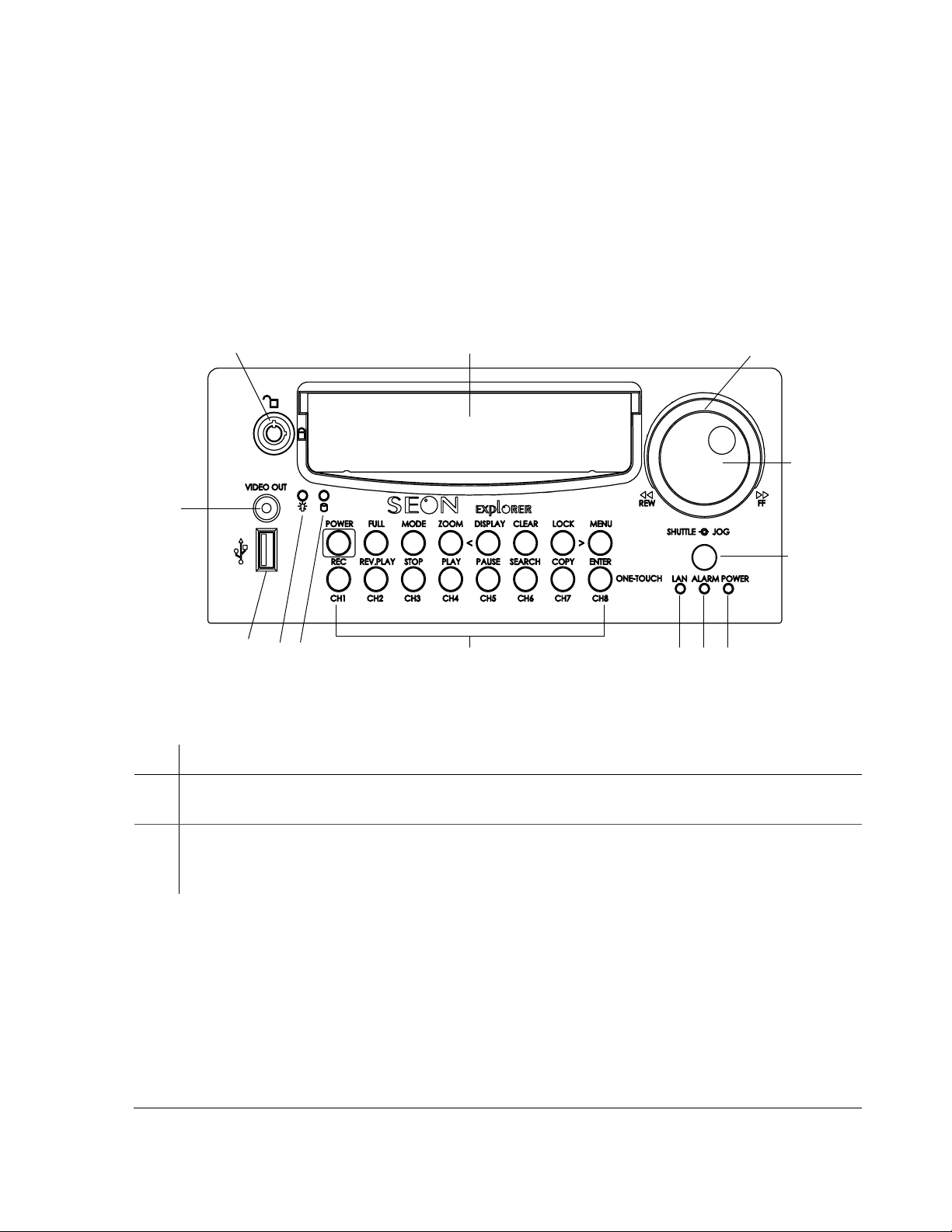
The EX8 Plus DVR has important features on the front of the unit such as the hard
drive lock, removable hard drive,
buttons for selecting menus and changing settings, the
OUT jack. See Figure 1-1.
Introduction
SHUTTLE/JOG wheel, indicator lights, the DVR
USB port, and the VIDEO
1
13
12 11
Figure 1-1
Table 1-1
Item Description
EX8 Plus DVR front panel
Front panel features
10
2
9
78
3
4
5
6
1 Hard Drive lock (unlocked and locked positions) requires the proper key to unlock the hard drive
prior to removal and locking the hard drive during operation.
2 Removable Hard Drive lets you remove the hard drive for playback at a remote location using the
HD Reader (see “4.4. Downloading Video to a PC” on page 4–6), swap to another DVR, or
upgrade to a larger hard drive.
700-0048 R003 1–3
Page 18

Introduction
Table 1-1
Item Description
Front panel features
3 SHUTTLE wheel (outer wheel)
1. During playback, turning the
SHUTTLE wheel clockwise speeds the play forward from 1× to
2×, 4×, 6×, 8×, 16× and 32× the normal speed.
2. During reverse playback, turning the
SHUTTLE wheel counter clockwise speeds the play
backward from 1×, 2×, 4×, 6×, 8×, 16× and 32× the normal speed.
3. When the
PAUSE button is pressed, turning the SHUTTLE wheel clockwise reduces the play to a
very slow forward rate.
4. When the
PAUSE button is pressed, turning the SHUTTLE wheel counter clockwise reduces the
play to a very slow backward rate.
4
JOG wheel (inner wheel)
1. Used to change the values of menu items.
2. When pause button is pressed, turning the jog wheel clockwise or counter clockwise moves
the image one at a time.
5 Infrared (IR) Remote Control receiver is used with the optional IR remote control pointed at the
receiver.
6
POWER—DVR Power indicator (green) illuminates when the DVR is powered up.
7
ALARM—Alarm Event indicator (red) illuminates when an external alarm input has been initiated
and remains illuminated for the duration of the alarm.
LAN—Network indicator (red) illuminates when connected to an active network.
8
9 DVR Buttons (See Table 1-2.)
10 Hard Drive Access indicator (yellow) illuminates when the DVR is accessing the hard drive.
11 Hard Drive Power indicator (green) illuminates when the hard drive has been properly inserted in
the hard drive tray, and the hard drive lock has been turned to the locked position.
12 USB Port supports USB devices for:
1. Copying video and audio information
2. Exporting video clips (See “4.5.2. Using the ONE-TOUCH Download option” on page 4–7.)
3. Updating the DVR software
4. Importing/exporting operating settings and profiles.
13
VIDEO OUT—Video Output jack (yellow) used for:
1. Live viewing
2. Playback
3. System configuration.
This
VIDEO OUT jack has the same function as the VIDEO OUT jack on the back of the DVR. Only
one device at a time can be connected to either jack.
1–4 700-0048 R003
Page 19

1.3.2. DVR Buttons
The DVR buttons on the front panel will illuminate when the buttons are
activated. The DVR buttons perform more than one function and are described
briefly in Table 1-2.
Chapter 4, “Operating the DVR” provides detailed information on using the DVR
buttons. See “4.1.1 Using the DVR buttons” on page 4–2.
Introduction
Table 1-2
Button Description
POWER With the vehicle ignition turned OFF and the DVR powered off, pressing the POWER
Description of DVR buttons
button for 3 seconds will power up the DVR, but does not initiate recording.
With the vehicle ignition turned
DELAY-OFF interval, pressing the POWER button for 5 seconds will power down the
OFF and the DVR still powered up in the RECORD
DVR immediately.
With the vehicle ignition turned
the
RECORD DELAY-ON interval powers up the DVR and starts recording.
FULL Use the FULL button in combination with one of the eight camera buttons (CH1, CH2,
CH3, CH4, CH5, CH6, CH7, OR CH8) and the DVR will display the selected camera in
ON, pressing the POWER button for 5 seconds during
full screen display mode.
MODE Pressing the MODE button changes the display.
ZOOM In full screen display mode, pressing the ZOOM button lets you zoom into the screen
2×.
DISPLAY <
While the DVR is recording in live mode, different information can be displayed on
the screen.
<
CLEAR When configuring the DVR, pressing the CLEAR button will load the factory default
The < button is used to navigate the menus while configuring the DVR.
value into the field being edited.
LOCK >
>
MENU Pressing the MENU button enters and exits the main menu of the DVR.
REC (CH1) Pressing the REC button starts the DVR recording if the DVR is not playing video or
REV.PLAY (CH2) During playback or when the video is stopped, press the REV.PLAY button to start
Pressing the LOCK button enables a One-Time password option.
The > button is used to navigate the menus while configuring.
in the menus. When the DVR is recording, the
REC button is illuminated.
playing the video in reverse.
STOP (CH3) Pressing the STOP button stops the DVR from recording or playing.
700-0048 R003 1–5
Page 20

Introduction
Table 1-2
Button Description
PLAY (CH4) If the DVR is not recording, pressing the PLAY button will start to play the recorded
Description of DVR buttons
video and audio.
PAUSE (CH5) Pressing the PAUSE button pauses the video playback and provides a still frame video
image.
SEARCH (CH6) Pressing the SEARCH button provides a power search function that lets you quickly
find the desired information. Exit the Search menu by pressing the
COPY (CH7) Pressing the COPY button take you to the Copy menu. Exit the Copy menu by
MENU button.
ENTER button lets you navigate to the
ONE-TOUCH button starts One-touch download. For more information,
ENTER/ONE-
TOUCH (CH8)
pressing the
While configuring in the menus, pressing the
selected sub-menu.
Pressing the
MENU button.
see “4.5.2. Using the ONE-TOUCH Download option” on page 4–7.
1–6 700-0048 R003
Page 21
1.3.3. DVR Back Panel Features
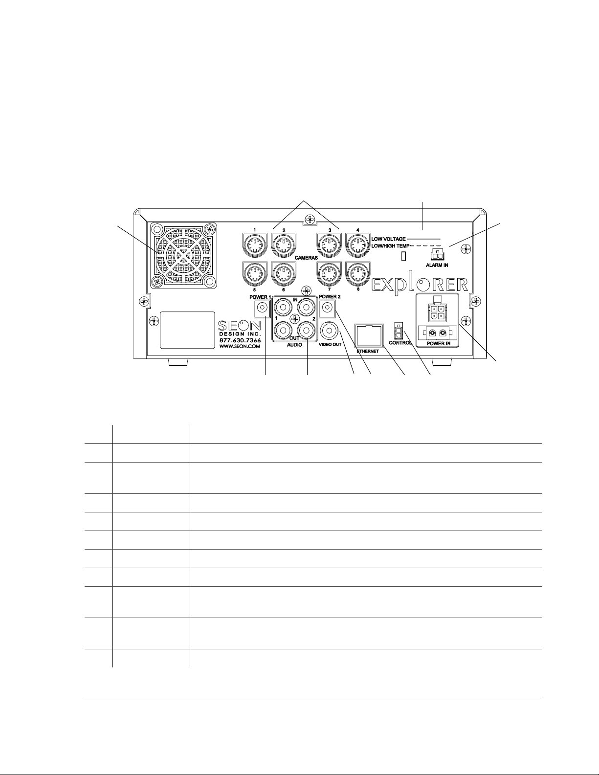
The back panel of the EX8 Plus DVR features the inputs where the DVR connects
to the other components of the EX8 Plus System. See Figure 1-2.
Chapter 2, “Installation” provides detailed information on connecting to the back
panel. See “2.5.1. Connecting to the DVR Back Panel” on page 2–7.
Introduction
1
10
Figure 1-2
Item Feature Description
Back panel
9
8
1 CAMERAS Camera input connectors: 6-pin mini-DIN
2 LOW VOLTAGE
LOW/HIGH TEMP
Low voltage and Low/High temperature indicator (red)
2
3
4
9
67
5
ALARM IN Alarm input connector: 2-pin
3
4
POWER IN Power input connectors: 4-pin and 2-pin
CONTROL Control connector: 2-pin
5
6
ETHERNET Network connector: RJ-45
7
VIDEO OUT Video output jack: Yellow RCA style
AUDIO IN 1, 2
8
AUDIO OUT 1, 2
9
POWER 1
POWER 2
FAN Fan with filter and removable cover
10
700-0048 R003 1–7
Audio input jacks: White RCA style for Audio In
Audio output jacks: Red RCA style for Audio Out
Auxiliary Power jacks: 2.1 mm barrels
Page 22

Introduction
1.4. Lock Box
The lock box secures the DVR into a location on the bus and provides the
following features:
• A locking door which prevents unauthorized access to the DVR controls.
Authorized personnel can use the lock box key to remove the hinged locking
door when access to the DVR is necessary.
• A sliding rail system which allows for easy DVR installation and exchange.
• A slotted cable entry allows connectors to be inserted into the lock box after
installation.
• A removable, hinged locking door, rounded to prevent injury from sharp
edges.
• Mounting patterns that can accommodate installation flat on the floor,
vertically on the floor, or under a seat. (For installing the DVR under a seat,
use of the Underseat Mounting Bracket Kit is recommended. For installing
the DVR in a vertical mount, the Vertical Mounting Bracket Kit is
recommended. Contact your sales representative at Seon Design for more
information.)
1.5. Cables and Harnesses
The wiring connections to the EX8 Plus System includes:
• A 20 foot or 50 foot camera cable comes with the camera, using a single
connector for ease of installation.
• An ignition input harness.
• A high-reliability power harness for providing power to the DVR.
• A driver’s indicator panel to allow easy event searching on the DVR.
• In-line fuses on the power and ignition lines for added protection.
1–8 700-0048 R003
Page 23

CHAPTER 2
Installation
This chapter provides information and procedures for installing the EX8
Plus System.
Page 24

Installation
2.1. Installing the EX8 Plus DVR and Lock Box
The EX8 Plus DVR is designed to be installed in the lock box which is secured to
the mounting surface using the screws provided. The lock box can be installed flat
on the floor or under a seat (horizontal installation) or vertically on the floor
(vertical installation), depending on your requirements. The lock box has a
removable, hinged locking door, and a slide rail system to allow for easy
installation and exchange of the DVR.
The EX8 Plus DVR has connections to the front and back of the unit which are
secured once the DVR is installed and the lock box is locked. Cable grommets on
the lock box allows connectors to be inserted into the lock box after installation.
Planning an
installation
Materials required You will need these materials to complete the installation:
Check that you have all the system components and inspect the units for any
scratches or damage. The lock box key is required to unlock the door of the lock
box and remove the components that are placed inside the box for shipping such
as cameras and harnesses.
• EX8 Plus DVR
• DVR keys for securing the removable hard drive
• Lock box
• Lock box keys for securing the hinged locking door
• Cameras
• Driver’s indicator panel
• Seon video recording label (if purchased)
• Smart-Link™ module
• Smart-Link-to-DVR connection harness (10 feet)
• Ignition harness (20 feet)
• Fuse: 1 A ignition fuse
• Fuse holder
• Power harness (23 feet)
• Fuse: 10 A power fuse
• Fuse holder
• Alarm input cable (3 feet)
• Signal harness (3 feet)
• Speed cable (20 feet) (if purchased)
• GPS receiver and cable (if purchased)
• CAN interface cable (if purchased)
• Butt splice connectors
• Four #10 × ¾" sheet metal screws
• Four #10 × 1" self-drilling screws
2–2 700-0048 R003
Page 25

Installation
Longer cables To customize your installation, longer cables are available by contacting your
sales representative at Seon Design.
Important note
Important:
Design sales representative or dealer for information on the Underseat Mounting Bracket
Kit before starting the installation.
Important:
Design sales representative or dealer for information on the V ertical Mounting Bracket Kit
before starting the installation.
If you are mounting the lock box under a seat, please contact your Seon
If you are mounting the lock box vertically, please contact your Seon
2.2. Step 1: Installing the Lock Box
The lock box has a door and lid which will need to be removed in order to secure
the base in its location. The lock box can be mounted either on the floor or
underneath a seat.
Important:
sales representative or dealer for information on the Underseat Mounting Bracket Kit.
The lock box can be installed horizontally (see “2.2.1. Horizontal Installation”).
Four mounting points are located on the base of the lock box for securing the unit
and raising the unit off the mounting surface by 3/16".
The lock box can be installed vertically (see “2.2.2. Vertical Installation” on
page 2–4). Three mounting points are located on the back of the unit for securing
the unit and raising the unit off the mounting surface by 3/16".
If you are mounting the lock box under a seat, contact your Seon Design
Important:
where the cables enter the unit.
It is not recommended that the lock box be installed on its left or right side
2.2.1. Horizontal Installation
To install the lock box horizontally:
1. Unlock the door with the lock box key provided and remove it from the base
of the lock box.
2. Slide the DVR out of the lock box by pulling on the two bracket tabs at the
front of the DVR.
3. Detach the lid from the lock box by removing the two retaining screws on
either side of the lid near the front of the lock box.
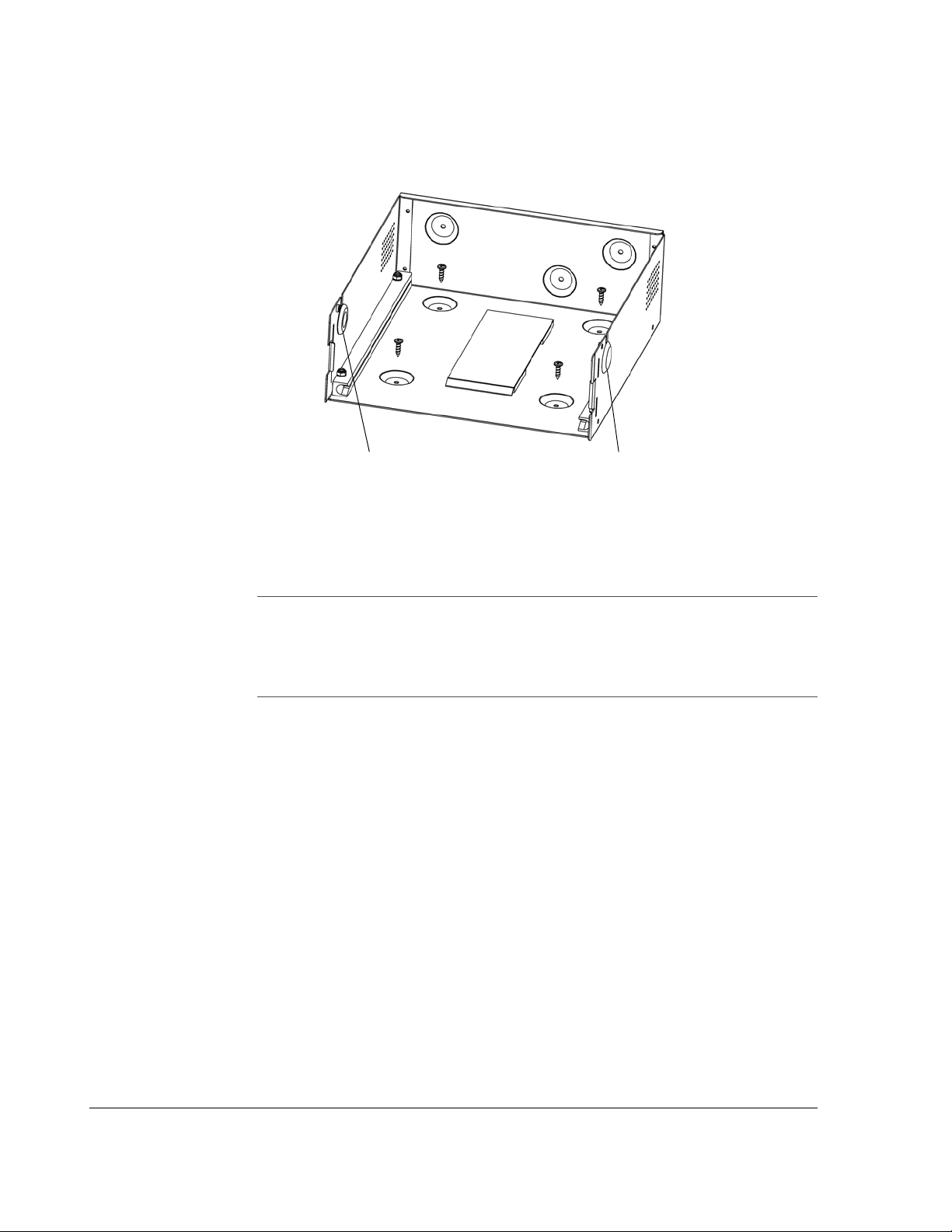
4. Determine whether the power and camera cables will enter the lock box on
the left or the right side. Swap the cable grommet and the hole plug, if
necessary. See Figure 2-1.
5. Use the four #10 × ¾" sheet metal screws or #10 × 1" self-drilling screws to
secure the base of the lock box to the floor.
700-0048 R003 2–3
Page 26
Installation
6. Slide the lid on to the lock box and secure it with the two retaining screws.
Cable grommet Hole plug
Figure 2-1
2.2.2. Vertical Installation
For installation in a difficult location, the lock box can be mounted vertically.
Important:
help stabilize the lock box in a vertical installation. If you are mounting the lock box
vertically , please contact your Seon Design sales representative or dealer for information
on the Vertical Mounting Bracket Kit before starting
the installation.
To install the lock box vertically:
1. Unlock the door with the key provided and remove it from the base of the lock
box.
2. Slide the DVR out of the lock box by pulling on the two bracket tabs at the
front of the DVR.
3. Detach the lid from the lock box by removing the two retaining screws on
either side of the lid near the front of the lock box.
4. Determine whether the power and camera cables will enter the lock box on
the left or the right side. Swap the cable grommet and the hole plug, if
necessary.
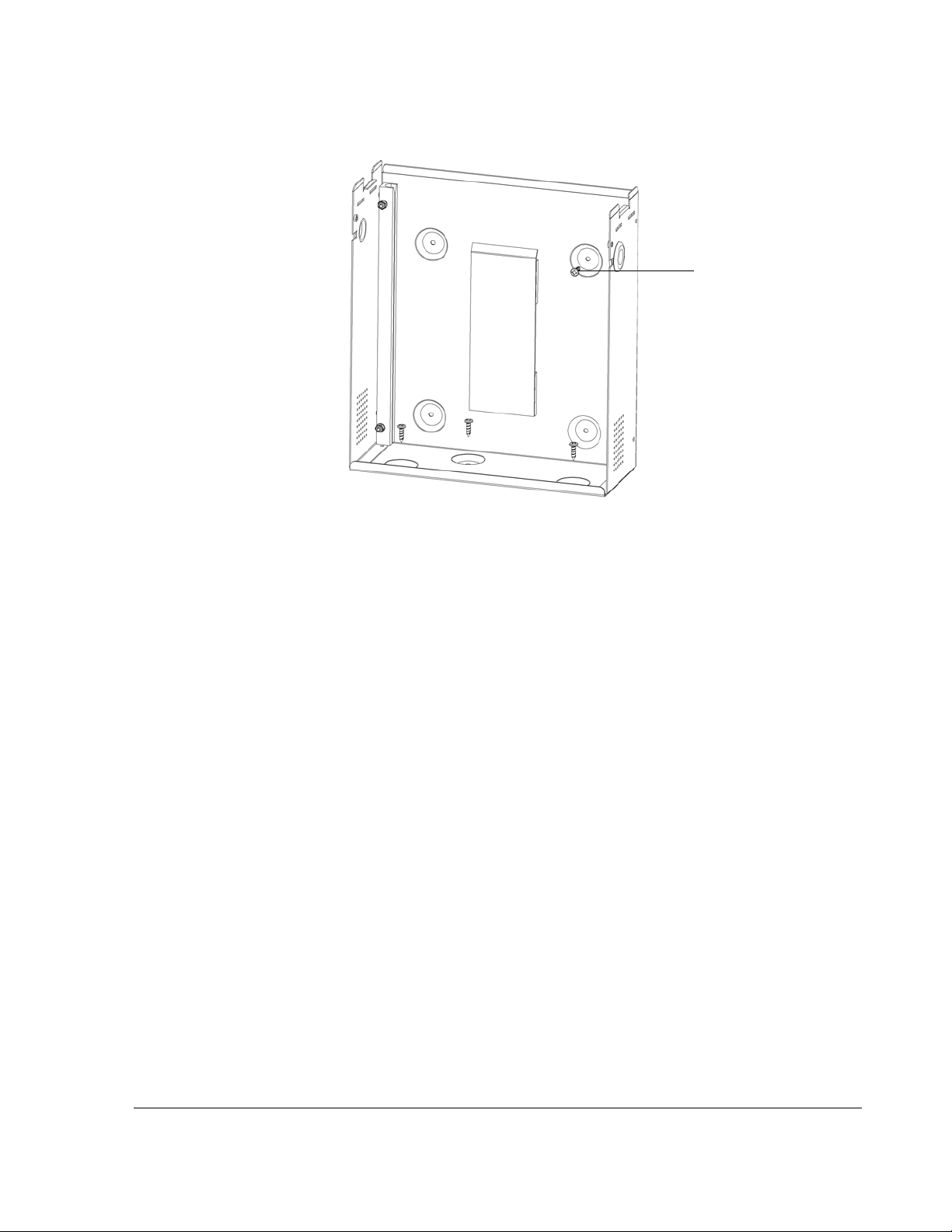
5. Use 3 of the enclosed #10 × ¾ sheet metal screws or #10 × 1 self-drilling
screws to attach the lock box to the floor. See Figure 2-2.
6. To prevent excess vibration, use the remaining #10 × ¾ sheet metal screw or
#10 × 1 self-drilling screw to secure the lock box to a vertical surface.
7. Reattach the lock box lid using the two screws removed earlier.
Lock box horizontal installation
It is highly recommended that the V ertical Mounting Bracket Kit is used to
2–4 700-0048 R003
Page 27
Installation
Vertical mounting
screw
Figure 2-2
Lock box vertical installation
2.3. Step 2: Installing the DVR in the Lock Box
The DVR has two brackets attached to the sides that allow it to slide easily in and
out of the lock box. The brackets also enable easy top-up orientation of the DVR
when the unit is installed on the floor or under a seat.
The rear of each bracket has two plastic retainers that allow cables to easily slip in
between to ensure they do not get pinched at the back of the lock box when the
DVR slides in.
2.4. Step 3: Installing the Cameras
If you have purchased cameras from Seon Design, install the cameras according
to the documentation that shipped with the product.
If you have cameras already installed, see “2.4.1. Checking the Camera Cable
Connections”.
2.4.1. Checking the Camera Cable Connections
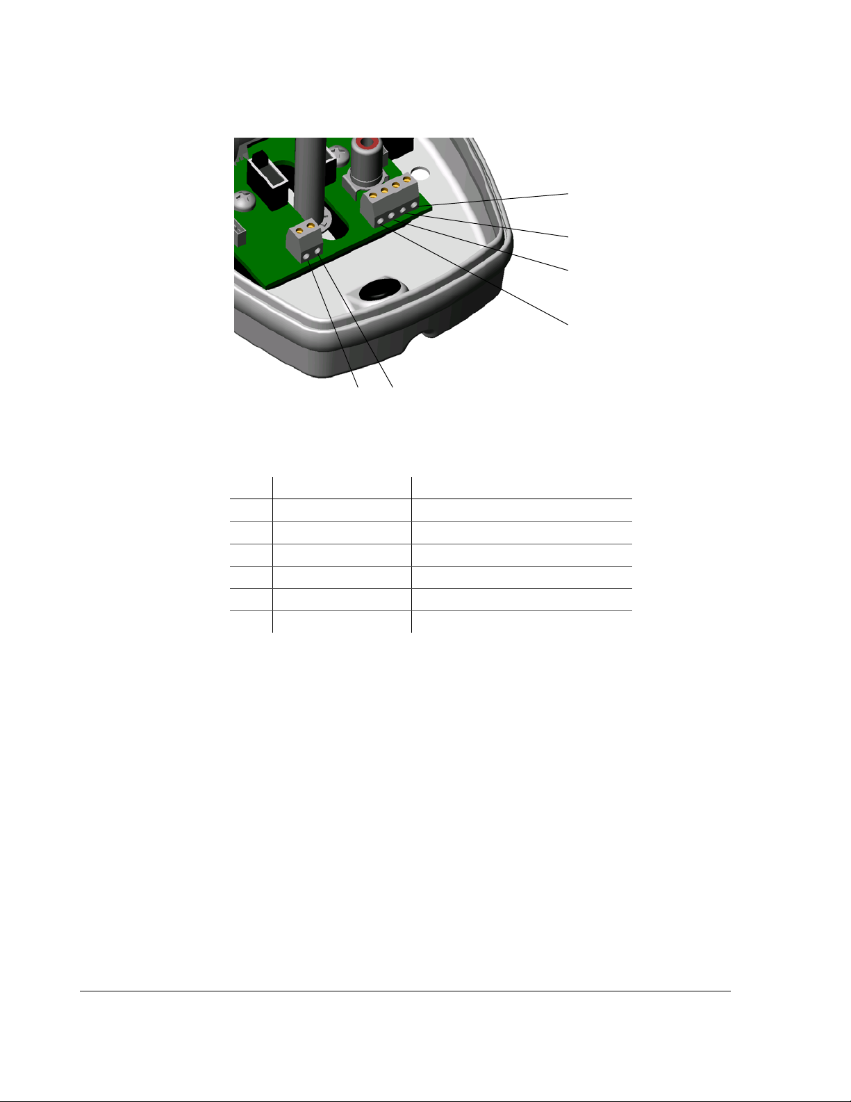
The EX8 Plus System uses an integrated mini-DIN connector for all of the camera
signals. The cable comes prewired into the camera, but in the event that the cable
becomes disconnected, reattach into the terminal blocks inside the camera. See
Figure 2-3. The cable colors for correct wiring to the terminals are described in
T able 2-1. For comp lete camera information, see the product insert for the camera
(for example, SA Series Wedge Camera Setup Guide document part number 700-
0004).
700-0048 R003 2–5
Page 28
Installation
1
2
3
4
5
6
Surface run
Installation
Concealed
Installation
Figure 2-3
Table 2-1
Item Color Description
Terminal blocks in the camera
Camera cable wiring
1 Red Power positive (+)
2 Black (and silver) Power ground (–)
3 Green Audio positive (+)
4 White Audio ground (–)
5 Yellow or orange Video positive (+)
6 Blue or brown Video ground (–)
The camera cable is 20 feet or 50 feet in length and should be long enough to
reach from a camera mounted to the header or ceiling of a bus down to the DVR
lock box. Different cable lengths can be obtained by contacting Seon Design.
The camera cable can be surface run or concealed.
If the installation is surface run, ensure that the camera cable is secured at multiple
points and is protected from sharp corners.
If the cable is concealed, it can be pulled from either end. Pulling from the
connector end will require larger holes in panels. Pulling from the wire end will
require the cable to be disconnected from the camera.
Feed the cable through the large cable grommet on the DVR lock box. The
connectors can be fed through the grommet one at a time, or the grommet can be
cut at the top and the cables can be simply slid into the grommet. Leave enough
cable in the DVR lock box to allow the DVR to slide all the way back.
2–6 700-0048 R003
Page 29
2.5. Step 4: Connecting the DVR
2.5.1. Connecting to the DVR Back Panel
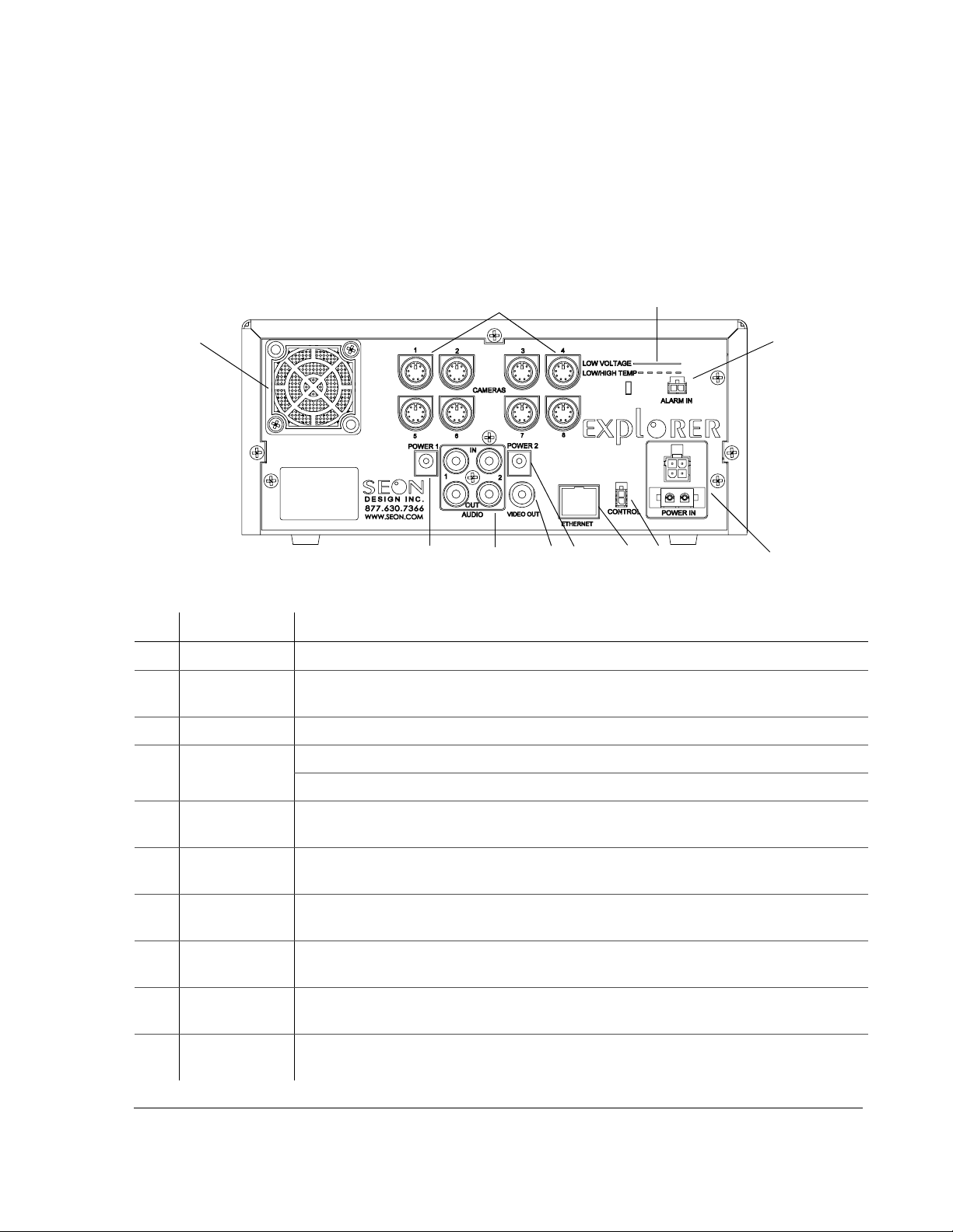
Figure 2-4 shows the back panel of the EX8 Plus DVR which provides the
connectors for the camera inputs, alarm input cable, power input harness, control
cable, Ethernet, video in and out, audio in and out, and power.
Installation
1
10
Figure 2-4
Item Feature Description
Back panel connections
9
8
7
1 CAMERAS Eight camera input connectors: 6-pin mini-DIN
2 LOW VOLTAGE
LOW/HIGH TEMP
3
ALARM IN Alarm input connector (2-pin) for connecting the alarm input cable.
Low voltage and Low/High temperature indicator (red) illuminates if the voltage is low.
(See “4.6. Voltage Display” on page 4–13.)
2
3
9
5
6
4
4
POWER IN Power input connector (4-pin) for connecting the Smart-Link-to-DVR harness.
Power input connector (2-pin) for connecting the power harness.
5
CONTROL Cont rol connector (2-pin) for connecting external devices and controlling the wireless
bridge equipment.
6
ETHERNET Network connector: RJ-45 for connecting to LAN. Ethernet is used to connect either to a
PC or directly to the wireless bridge equipment.
7
VIDEO OUT Video output jack (yellow RCA style) for plackback. (A video output jack is also provided
on the front panel of the DVR. Only one device at a time can be connected to either jack.)
8
AUDIO IN 1, 2
AUDIO OUT 1, 2
9
POWER 1
POWER 2
10
FAN Fan with filter and removable cover keeps the un it cool. (For maintaining the filter, see
Audio input jacks (white RCA style) used with the two power output jacks for optional
remote microphones or IR modules. Audio output jacks (red RCA style) for playback.
Auxiliary Power jacks (2.1 mm barrels)
“5.1.3. Replacing the Fan Filter” on page 5–2.)
700-0048 R003 2–7
Page 30
Installation
To connect to the back of the DVR:
1. Plug the 6-pin mini-DIN connector from each camera into the mating
connector on the back of the DVR. See Figure 2-4.
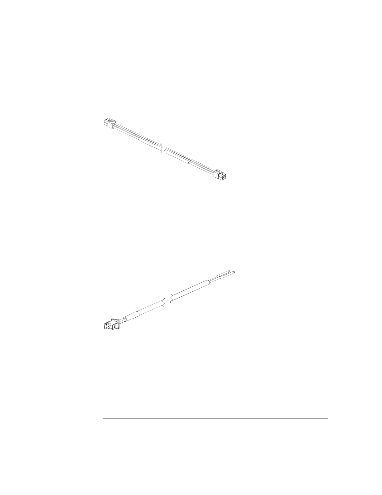
2. Plug one end of the Smart-Link-to-DVR connection harness into the
IN connector. The connectors on the harness are identical so that either end
can be plugged into either device. See Figure 2-5.
POWER
Figure 2-5
Smart-Link-to-DVR connection harness
The other end of the Smart-Link-to-DVR connection harness is connected
once the Smart-Link module has been installed. See “2.7. Step 6: Installing
the Smart-Link™ Module” on page 2–10.
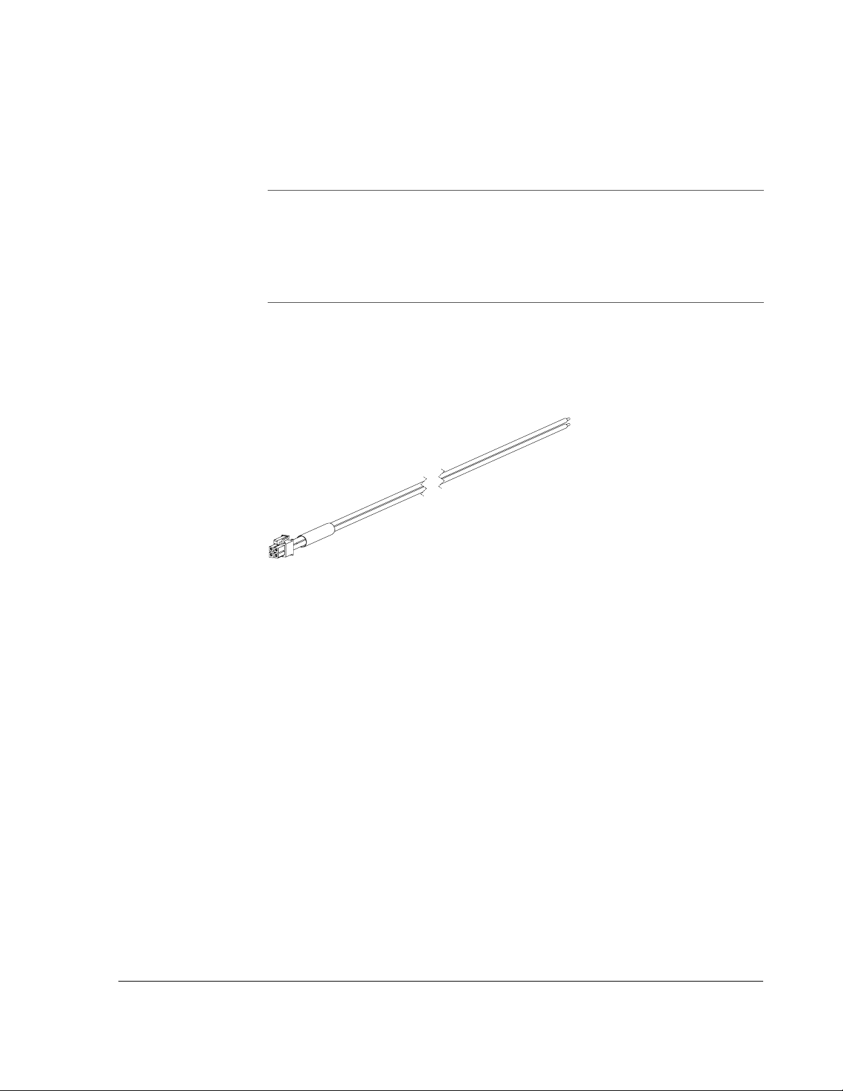
3. Plug the power harness into the 2-pin power input connector. See Figure 2-6.
4. Connect the red positive and black negative wires to the battery when
connecting the power harness. See “2.6. Step 5: Connecting the Ignition
Harness, Power Harness, Fuses and Fuse Holders”.
Figure 2-6
Power harness
5. If an optional external microphone is being used, plug the power connection
into either
POWER 1 or POWER 2.
6. Plug the
RCA connector into the AUDIO IN 1 or AUDIO IN 2 jack. See “2.4.1.
Checking the Camera Cable Connections” on page 2–5 about disconnecting
the audio from a camera when using the external microphone.
7. Push the cables into the cable retainers on the back of the DVR brackets and
slide the DVR into the lock box.
Important:
lock box.
2–8 700-0048 R003
Take care not to pinch or bind any cables when sliding the DVR into the
Page 31
2.6. Step 5: Connecting the Ignition Harness, Power Harness, Fuses and Fuse Holders
Installation
Important:
• protecting the yellow ignition trigger wire on the ignition harness. The ignition trigger
fuse holder uses the 1 A automotive blade fuse.
• protecting the red battery positive wire on the power harness. The red positiv e wire
fuse holder uses the 10 A automotive blade fuse.
Use the butt-splice connectors to connect the fuse holders to their respective wires.
The two in-line automotive fuse holders are for:
2.6.1. Connecting the Ignition Harness
The ignition harness uses a 22 AWG yellow wire to connect to an ignitionswitched circuit. See Figure 2-7. The 1 A fuse and in-line fuse holder is supplied
for protecting the yellow ignition trigger wire.
Figure 2-7
Ignition harness wires
To connect the ignition harness:
1. Connect the black negative (–) battery power wire to the battery’s negative
(–) terminal. If there is a master battery switch in the battery compartment
connected to the battery’s negative (–) terminal, then connect the black
negative (–) battery power wire after the battery switch.
2. The in-line fuse holder consists of a black plastic piece with an attached cap
that simply pulls apart. Install the 1 A fuse and push the holder back together.
3. Strip the yellow wire end appropriately. A butt splice connector is supplied to
connect the fuse holder to the yellow wire. Connect the other end of the fuse
holder to an ignition-switched circuit.
The connector on the ignition harness is plugged into the Smart-Link once the
Smart-Link has been installed. See “2.7. Step 6: Installing the Smart-Link™
Module”.
700-0048 R003 2–9
Page 32

Installation
2.6.2. Connecting the Power Harness to the Battery
The power harness uses a pair of 14 AWG power wires to connect to the vehicle
battery. See Figure 2-6.
The supplied in-line automotive fuse holder is for protecting the red positive (+)
battery wire. A 10 A fuse and in-line fuse holder is supplied for the red positive
(+) battery power wire.
Important:
drop (reduced voltage from the battery to the DVR). If the voltage drop is too large, then
the DVR detects the low voltage and stops recording to protect itself. If the voltage stays
low for too long, the DVR interprets this as meaning the vehicle battery is drained and the
DVR shuts down completely.
Connecting the power farther from the battery results in a larger voltage
To connect the power harness to the battery:
1. Connect the black negative (–) battery power wire to the battery’s negative
(–) terminal. If there is a master battery switch in the battery compartment
connected to the battery’s negative (–) terminal, then connect the black
negative (–) battery power wire after the battery switch.
2. The in-line fuse holder consists of a black plastic piece with an attached cap
that simply pulls apart. Install the 10 A fuse and push the holder back
together.
3. Strip the red wire end appropriately. A butt splice connector is supplied to
connect the fuse holder to the red battery power wire. Connect the other end
of the fuse holder directly to the battery’s positive (+) terminal.
2.7. Step 6: Installing the Smart-Link™ Module
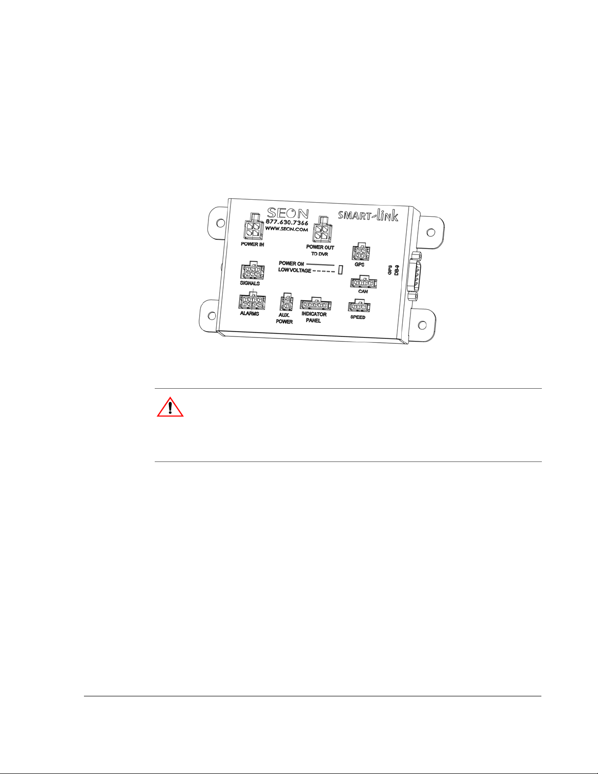
The EX8 Plus DVR uses the external Smart-Link module to provide interface
connections to a variety of different signals. See Figure 2-8.
The Smart-Link is designed to be installed into the electrical compartment of a
vehicle, reducing the number of cables that connect to the DVR and reducing the
lengths of interface harnesses and cables that connect to the vehicle systems.
If you need assistance in determining a suitable location to mount the Smart-Link,
contact Customer Service at Seon Design. (The dimensions for the Smart-Link are
provided in “A.5. Smart-Link™ Module” on page A–4.)
To install the Smart-Link module:
1. Mount the Smart-Link on a vertical surface to avoid having liquids pool on
the bottom.
2. Mount the Smart-Link using the four #1 0 × ¾" sheet metal screws or the four
#10 × ¾" self-drilling screws.
3. Verify that one end of the Smart-Link-to-DVR connection harness is
connected to the
POWER IN connector on the back of the DVR. The connectors
on the harness are identical so either end can be plugged into either device.
2–10 700-0048 R003
Page 33
Installation
4. Plug the other end of the Smart-Link-to-DVR connection harness into the
POWER OUT TO DVR connector on the Smart-Link.
5. Plug the ignition harness (shown in Figure 2-7) into the
POWER IN connector
on the Smart-Link.
6. Connect the red wire to a 12 VDC battery connection. Connect the black wire
to a ground connection. Connect the yellow wire to an ignition-triggered
signal.
Figure 2-8
Smart-Link module
CAUTION
T o ensure proper performance, connect the red and black power wires to points as close to
the battery as possible. Never connect the ground wire (black wire) to the vehicle chassis
by drilling a hole into a panel and using a sheet metal screw. The ground connection will
be corroded very quickly and the performance will be compromised.
700-0048 R003 2–11
Page 34
Installation
2.7.1. Connecting the Signal Harness
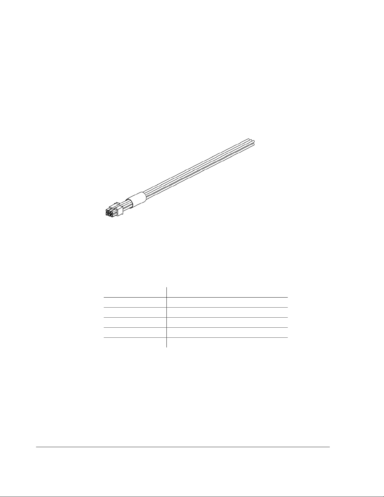
The 5-conductor signal harness shown in Figure 2-9 connects to the various
signals in the vehicle, including turn signals, brake lights, stop-arm, and warning
lights, for example. If the signals are not being used with the system, then this
harness does not have to be installed.
Always connect through a fuse-protected circuit. The signals can be activated
from 12 VDC (Active
Signals Menu” on page 3–22.
HIGH) or 0 VDC (Active LOW). See “3.2.7. Using the
Figure 2-9
3-foot Smart-Link signal harness
The wire colors for wiring to the indicators and default text are described in Table
2-2. The indicators can be hooked up to any signal as the text for each indicator
can be easily reprogrammed. For example, Indicator 2 can be connected to the
Wheel Chair Lift signal, and the text could be changed from
Table 2-2
Wire Color Indicators and Default Text
Signal harness wiring
STP to WCL.
Black Indicator 1 – LT (Left Turn Signal)
Green Indicator 2 – STP (Stop-Arm)
Red Indicator 3 – BRK (Brakes)
Brown Indicator 4 – WRN (Warning Lights)
White Indicator 5 – RT (Right Turn Signal)
To connect the signal harness connector to the Smart-Link module:
• Connect the signal harness connector into the
SIGNALS connector on the
Smart-Link module.
2–12 700-0048 R003
Page 35
2.7.2. Connecting the Speed Cable
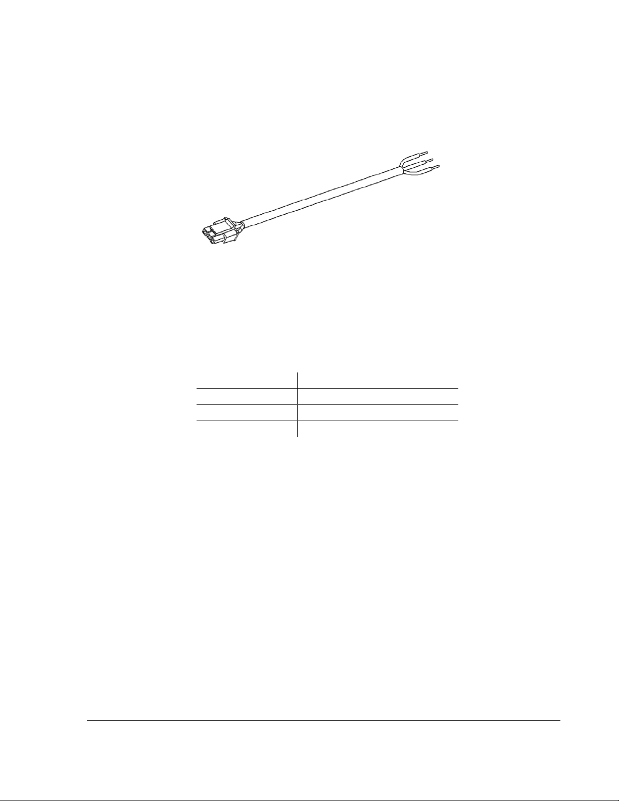
The 3-conductor speed sensor cable shown in Figure 2-10 is for connecting to an
optional speed signal sensor or to a transmission control module (TCM).
Installation
Figure 2-10
20-foot Smart-Link speed cable
Connecting to a Speed Signal Senor The wire cables for correct wiring to the
signals are described in Table 2-3. The green speed pulse signal is designed to
interface to speed sensors that output a pulse signal of up to 20 VDC, 20 VAC
p-p
or speed sensors that use open-collector style outputs. Contact Seon Design for
recommended speed sensors to use with the EX8 Plus System.
Table 2-3
Wire Color Signals
Speed cable wiring
Black Signal ground (0 V)
Green Speed pulse signal
Red Speed sensor power (7.5 VDC)
All of the wires in the speed sensor cable are protected against short circuits and
transients. Refer to the product documentation that comes with the speed sensor
for further information on connecting to an external speed sensor.
Connecting to a Transmission Control Module (TCM) The EX8 Plus DVR
has the ability to interface directly to some types of TCM in vehicles. Contact
Seon Design for further details about connecting the speed cable to different
TCMs.
To connect the speed cable to the Smart-Link module:
• Connect the speed cable connector into the
SPEED connector on the Smart-
Link.
700-0048 R003 2–13
Page 36
Installation
Indicat
2.8. Step 7: Installing the GPS Receiver
If you have not purchased a GPS receiver or if you wish to install the GPS
receiver at a later time, please proceed to “2.9. Step 8: Installing the Driver’s
Indicator Panel” on page 2–14.
Seon Design provides several models of GPS receivers designed to work with the
EX8 Plus System. Contact your sales representative at Seon Design for the GPS
receiver best suited for your application.
2.9. Step 8: Installing the Driver’s Indicator Panel
If you wish to install the driver’s indicator panel at a later time, please proceed to
“2.12. CAN Network” on page 2–16.
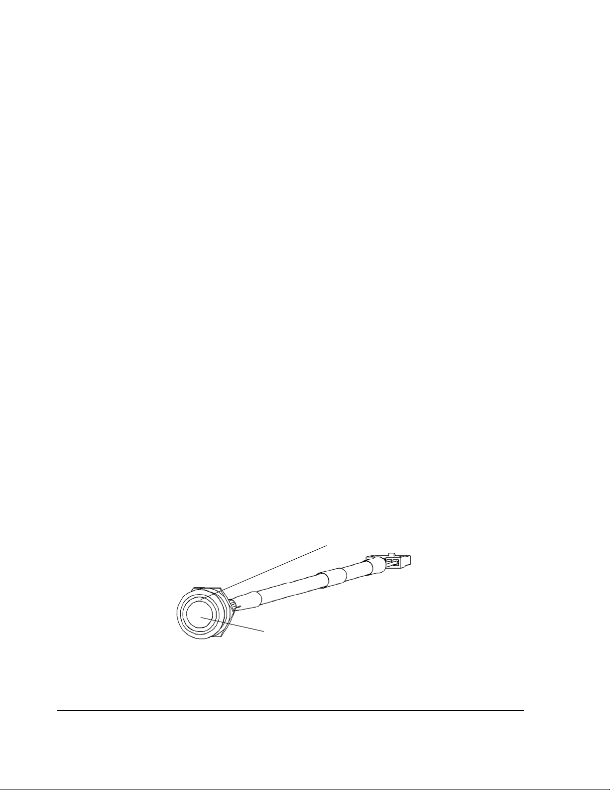
The EX8 Plus DVR with the Smart-Link module has an interface for a driver’s
indicator panel. The basic version of the panel consists of a heavy duty, vandalresistant switch with an integrated green indicator ring around the switch button.
See Figure 2-11. The indicator panel has a weather-sealing gasket attached to
prevent water penetration behind the device.
The indicator panel is supplied with a 12" cable and connector. A 10-foot
extension cable is provided as a standard accessory with the driver’s indicator
panel. Extension cables of different lengths can be ordered from Seon Design.
Please contact your sales representative to order a different length cable.
To install the indicator panel:
1. Drill a ¾" hole in the desired location. Ensure that the area behind the hole is
clear of obstructions before drilling.
2. Remove the mounting nut from the indicator panel.
3. If you have purchased the video recording label, install the label between the
button and the dashboard.
4. Feed the connector and cable through the mounting hole.
5. Reattach the nut.
or ring lamp
Alarm button
Figure 2-11
Driver’s indicator panel
2–14 700-0048 R003
Page 37

2.9.1 Status of the Driver’s Indicator Panel
Pushing the alarm button of the driver’s indicator panel causes an alarm event to
be recorded by the DVR. The button corresponds to Alarm 1 on the Smart-Link
alarm harness. The indicator ring indicates the status of the DVR. See Table 2-4.
Installation
Table 2-4
Ring Color Function
No green light No power to the DVR, or ignition is not on.
Flashing green The DVR is powered up, but not recording.
Solid green The DVR is powered up and recording.
Driver’s indicator panel status
2.10. Step 9: Hardware Installation Final Checklist
Harnesses (Camera, recorder, and accessories)
• Check for proper slack.
• Check that the cables and harnesses are properly secured.
• Check that sharp metal edges are not touching the cables or harnesses.
• Check that all the cables and harnesses are neat and tidy.
• Check that the connections are solid (no shorts).
Cameras
• Check for tight mount.
• Check the internal harness connections.
• Check that the lid is properly seated on the gasket and secured tightly.
• Check camera (s) field of view.
Recorder
• Check for tight mounting of hardware (lock box).
• Confirm that the cable grommet is properly installed.
• Check that all connections are tight.
System
• Install the fuses.
• Plug the video monitor into the DVR.
• Power up the system.
• Confirm that all the cameras and audio sources are operating properly.
• Confirm that all the status indicators react properly.
• Hard drive power indicator
• Hard drive (lock and access)
• Voltage, temperature or system alarms
• Switch to temporary power by pressing the front panel
vehicle ignition turned OFF.
• Test audio/video record and test audio/video playback.
• Configure the menus per the required end-user specifications.
POWER button with
700-0048 R003 2–15
Page 38

Installation
2.11. TR-INR Inertia Sensor
The TR-INR inertia sensor is a programmable accelerometer and impact sensor
that can measure rapid acceleration or deceleration, abrupt movement in bus
braking or turning which can lead to complaints or injury claims. Video footage
recorded with the sensor provides valuable information for reviewing incidents
and for training purposes as well. The inertia sensor has adjustable trigger
thresholds which can be wired to trigger alarms and signals. The unit measures
4.55" × 2.55" ×1.65" (H×W×D).
Contact your sales representative at Seon Design for TR-INR inertia sensor
options.
2.12. CAN Network
The EX8 Plus DVR has a built-in CAN interface for connecting to J1939
compliant vehicle networks. J1939 is a Society for Automotive Engineers (SAE)
specification for network communication in a vehicle. Seon Design can factory
program the Smart-Link module to accept ten signals from the large selection
available on a vehicle. For more information, please contact your sales
representative at Seon Design to discuss the CAN interface.
2.13. EZN Decoy System
The EZN decoy system uses a live camera that does not have to be changed from
bus to bus, only the DVR must be removed. For decoy systems, the lock box and
all the harness and cables are installed the same as for a live system.
2.14. Wireless Network
Contact your sales representative at Seon Design for wireless network options.
2–16 700-0048 R003
Page 39

CHAPTER 3
Configuring the DVR
This chapter provides information and procedures for configuring the DVR.
Page 40
Configuring the DVR
3.1. Configuring the DVR
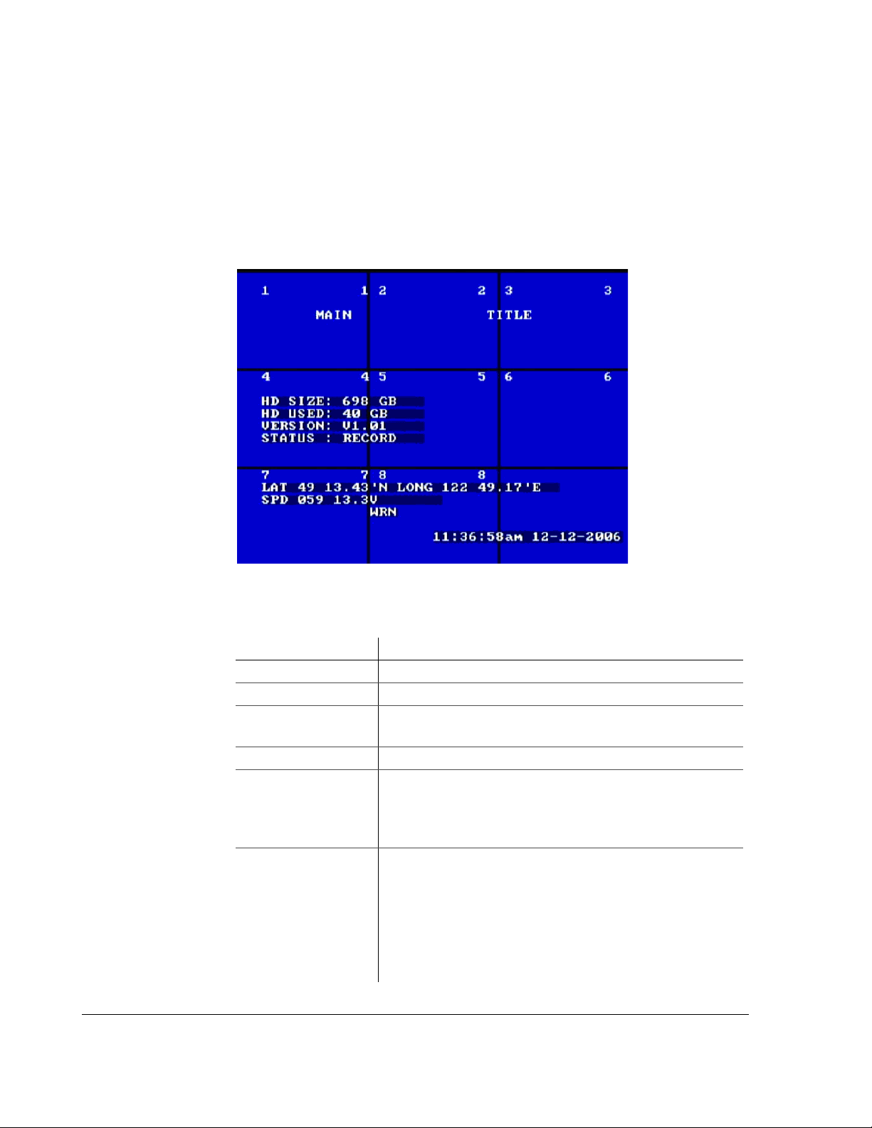
The EX8 Plus DVR uses on-screen configuring to allow for easy setup of all the
functions and controls. During live viewing and recording, the information
displayed on the screen can include the items shown in Figure 3-1. All menus are
displayed on a blue screen with white text.
Figure 3-1
Table 3-1
CAMERA TITLES
MAIN TITLE Identifies the system with a unique title.
HD SIZE The formatted size of the installed hard drive, measured
On-screen display during live viewing and recording
On-screen display information
Feature Description
Identifies the camera.
in gigabytes, GB.
HD USED Indicates how much of the hard drive has been recorded.
VERSION Indicates the software version of the DVR. When
contacting Seon Design about any service or operational
issues, please have the software version available. In the
above example, the software version is V1.01.
STATUS Indicates the operation status of the DVR. The options
are:
RECORD (Normal recording)
•
•
LIVE (Live mode not recording)
TIMER (Timer recording)
•
•
ALARM (Alarm recording)
•
V. LOSS (Video loss or came ra signal loss)
3–2 700-0048 R003
Page 41

Configuring the DVR
Table 3-1
GPS Information • LAT (Latitude)
SIGNALS Identifies the 10 different signals:
On-screen display information
Feature Description
LONG (Longitude)
•
•
SPD (Speed)
LT (Left)
•
•
STP (Stop)
BRK (Break)
•
WRN (Warning lights)
•
•
RT (Right)
FIVE USER-DEFINED CAN SIGNALS
•
Voltage Indicates the system voltage. See “4.6. Voltage Display”
on page 4–13.
Time and date Shows the time and date.
700-0048 R003 3–3
Page 42
Configuring the DVR
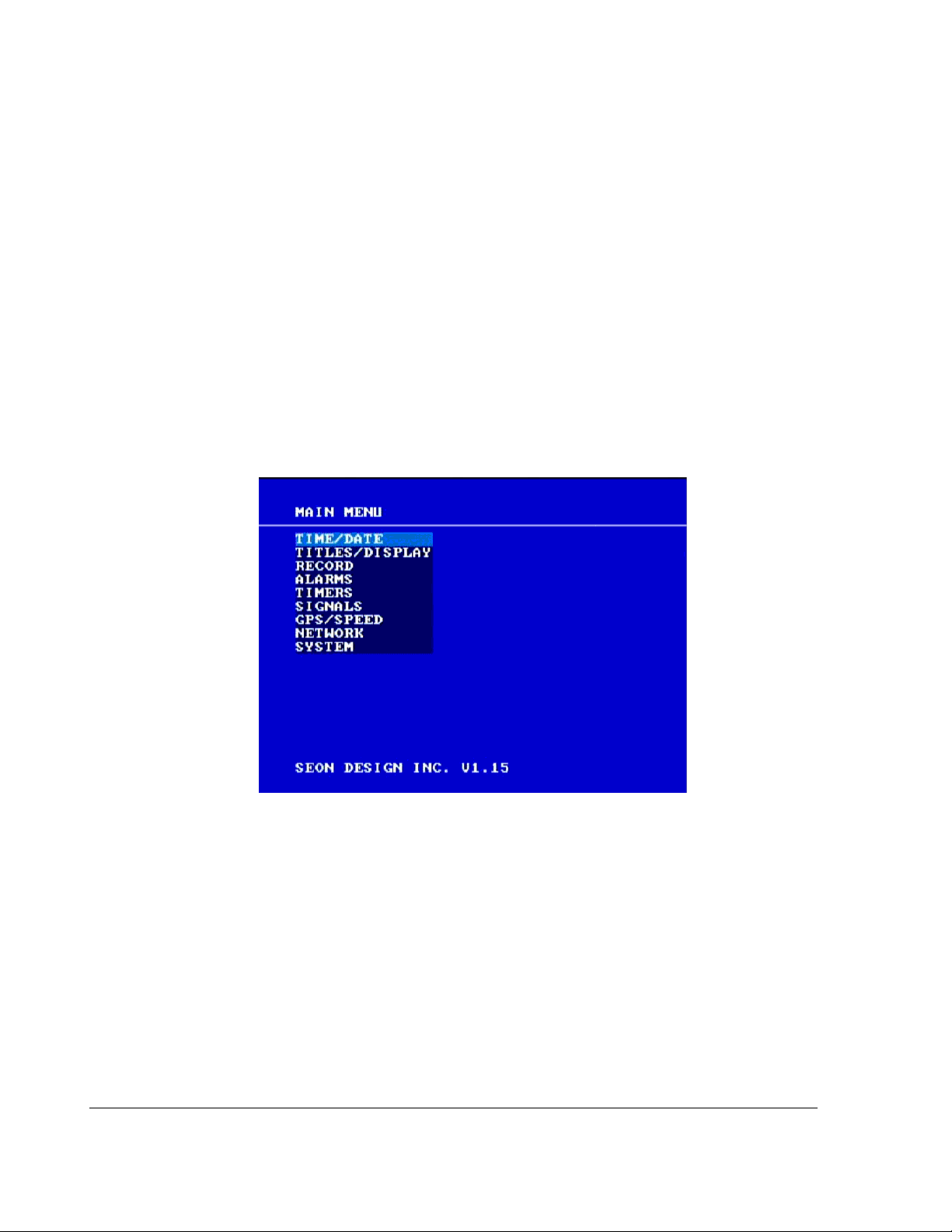
3.2. EX8 Plus DVR Main Menu
The EX8 Plus DVR main menu lets you set the time and date, create titles, and
customize other menu items.
To view the main menu:
1. If the DVR is recording or playing, press the
DVR.
2. Press the
3. Turn the
MENU button to display the main menu. Figure 3-2 appears.
JOG wheel (inner wheel) clockwise to scroll to the next item in the
menu.
OR
4. Turn the
Turning the
JOG wheel counter clockwise to scroll to the previous item.
JOG wheel continuously in either direction will present the menu
items in a continuous loop.
STOP button on the front of the
Figure 3-2
Main menu
To change a setting on the main menu:
1. On the main menu, turn the
JOG wheel to highlight the setting you want to
change.
2. Press the
3. Turn the
4. Press the
5. Press the
6. To exit the menu, press the
3–4 700-0048 R003
ENTER button to enter the menu.
JOG wheel to change the value.
LOCK > button to advance through the fields.
DISPLAY < button to move back through the fields.
MENU button.
Page 43
3.2.1. Software Version
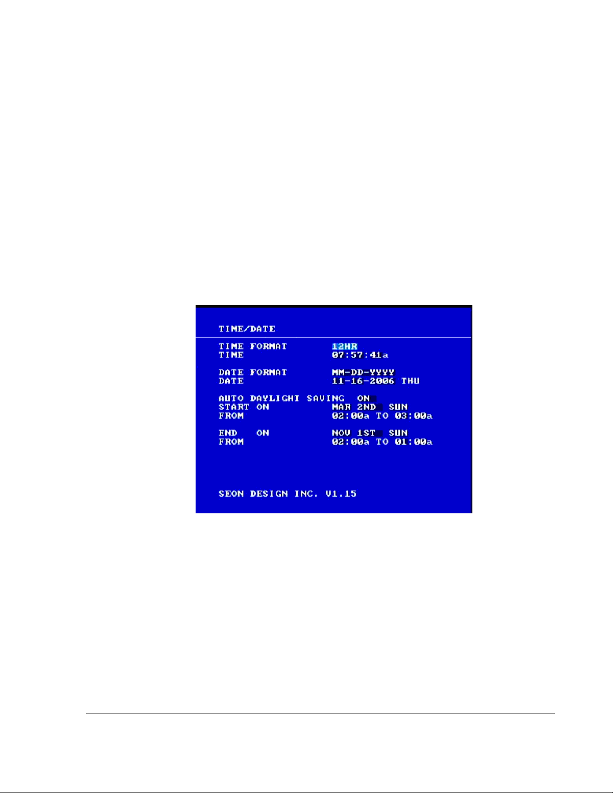
The software version in the DVR is displayed at the bottom of every menu. When
contacting Seon Design about any service or operational issues, please have the
software version available for Customer Service. In Figure 3-3, for example, the
software version is 1.15.
3.2.2. Using the Time/Date Menu
Use the Time/Dat e me nu to set the time format, time, date format, date, and the
daylight saving time options.
To view the Time/Date menu:
1. On the main menu, turn the
Configuring the DVR
JOG wheel to highlight TIME/DATE.
2. Press the
ENTER button.
The Time/Date menu appears as shown in Figure 3-3.
Figure 3-3
Time/Date menu
To change a setting on the sub-menu:
1. Turn the
2. Press the
3. Press the
JOG wheel clockwise or counter clockwise to change the value.
LOCK > button to advance through the fields.
DISPLAY < button to move back through the fields.
The selected menu item is highlighted with a pale blue background.
4. Press the
5. To exit the menu, press the
700-0048 R003 3–5
CLEAR button to reload the default value into a field.
MENU button.
Page 44

Configuring the DVR
6. Repeat these steps to set the Time Format, Time, Date Format, Date, Auto
Daylight Saving, Start On, From, End On, and From menu items.
See Table 3-2.
3.2.2.1. Time/Date Configuration Items
Table 3-2
Menu Item Description Value s Default
TIME FORMAT Set the time in 12-hour (am or pm
Time/Date configuration items
12HR, 24HR 12HR
indication) or 24-hour format.
TIME
DATE FORMAT Set the preferred date format. The
Set the time for the DVR. • 12:00:00a to 11:59:59p
• 00:00:00 to 23:59:59
MM/DD/YYYY, DD/MM/YYYY,
day of the week is automatically
YYYY/MM/DD
Not
applicable
MM
determined from the month, day , and
year settings.
DATE
Set the date for the DVR. The day of
the week is automatically
2-digit month, 2-digit day of
the year, 4-digit year
MM/DD/YYYY
determined from the month, day , and
year settings, for example, 11-162006 THU.
AUTO
DAYLIGHT
SAVING
The Auto Daylight Saving option set
ON will automatically adjust the
to
internal clock to daylight saving
ON, OFF ON
time. Beginning in 2007, on the
second Sunday in March, the time
will spring forward from 2:00:00 am
to 3:00:00 am.
On the first Sunday in November, the
time will fall back to Standard Time
by changing from 2:00:00 am to
1:00:00 am. The times and dates can
be adjusted as required.
/DD/YYYY
START
ON Set the month and week of the month
for daylight saving to start. For
example MAR 2nd SU.
• JAN, FEB, MAR, APR, MAY,
JUN, JUL, AUG, SEP, OCT,
NOV, DEC
MAR
2ND SUN
• 1ST, 2ND, 3RD, 4TH, LAST
• SUN, MON, TUE, WED, THU,
FRI, SAT
FROM
3–6 700-0048 R003
Set the time for daylight saving to
start.
• 12:00:00a to 11:59:59p
• 00:00:00 to 23:59:59
02:00a TO
03:00A
Page 45

Configuring the DVR
Table 3-2
Menu Item Description Val ue s Default
END ON Set the month and week of the month
Time/Date configuration items
for daylight saving to end, for
example, NOV 1st SU.
• JAN, FEB, MAR, APR, MAY,
JUN, JUL, AUG, SEP, OCT,
NOV, DEC
NOV
• 1ST, 2ND, 3RD, 4TH, LAST
• SUN, MON, TUE, WED, THU,
FRI, SAT
FROM
Set the time for daylight saving to
end.
• 12:00:00a to 11:59:59p
• 00:00:00 to 23:59:59
02:00a TO
01:00a
1ST SUN
700-0048 R003 3–7
Page 46
Configuring the DVR
3.2.3. Using the Titles/Display Menu
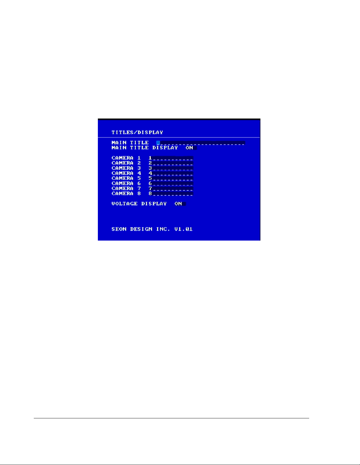
Use the Titles/Display menu to set the on-screen title and other on-screen options.
To view the Titles/Display menu:
1. On the main menu, turn the
2. Press the
ENTER button.
JOG wheel to highlight TITLES/DISPLAY.
The Titles/Display menu appears as shown in Figure 3-4.
Figure 3-4
Titles/Display menu
To change a setting on the sub-menu:
1. Turn the
2. Press the
3. Press the
JOG wheel clockwise or counter clockwise to change the value.
LOCK > button to advance through the fields.
DISPLAY < button to move back through the fields.
The selected menu item is highlighted with a pale blue background.
4. Press the
5. To exit the menu, press the
CLEAR button to reload the default value into a field.
MENU button.
6. Repeat these steps to set the Main Title, Main Title Display, Camera 1 to
Camera 8, and Voltage Display. See Table 3-3.
3–8 700-0048 R003
Page 47

3.2.3.1. Titles/Display Configuration Items
Configuring the DVR
Table 3-3
Menu Item Description Value s Default
MAIN TITLE The main title is displayed on every
Titles/Display configuration items
view and can be up to 24 characters
long.
• A to Z
•0 to 9
•and
Not
applicable.
• . (Period)
• , (Comma)
•+ (Plus)
• – (Dash)
• / (Forward slash)
• _ (Space)
MAIN TITLE
DISPLAY
CAMERA
CAMERA 2 2
CAMERA 3 3
CAMERA 4 4
1 The individual cameras can have
Set the main title display to ON or
OFF.
titles up to 10 characters long.
ON, OFF ON
• A to Z
1
•0 to 9
•and
• . (Period)
• , (Comma)
•+ (Plus)
CAMERA 5 5
CAMERA 6 6
• – (Dash)
• / (Forward slash)
• _ (Space)
CAMERA 7 7
CAMERA 8 8
VOLTAGE
DISPLAY
Displays the system input voltage for
diagnosing any potential problems
ON, OFF ON
with the system.
700-0048 R003 3–9
Page 48
Configuring the DVR
3.2.4. Using the Record Menu
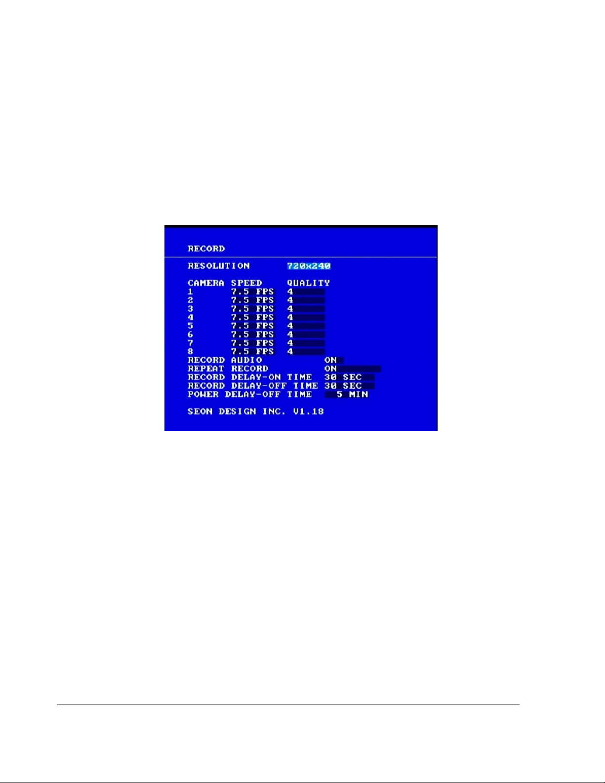
Use the Record menu to set the resolution, camera speed in frames per second
(FPS), the image quality, the Record Delay-On and Record Delay-Off times, and
other general recording options.
To view the Titles/Display menu:
1. On the main menu, turn the
2. Press the
The Record menu appears as shown in Figure 3-5.
ENTER button.
JOG wheel to highlight RECORD.
Figure 3-5
Record menu
To change a setting on the sub-menu:
1. Turn the
2. Press the
3. Press the
JOG wheel clockwise or counter clockwise to change the value.
LOCK > button to advance through the fields.
DISPLAY < button to move back through the fields.
The selected menu item is highlighted with a pale blue background.
4. Press the
5. To exit the menu, press the
CLEAR button to reload the default value into a field.
MENU button.
6. Repeat these steps to set the Resolution, Camera 1 to Camera 8 Speed and
Quality, Record Audio, Repeat Record, Record Delay-On Time, Record
Delay-Off Time, and Power Delay-Off Time. See Table 3-4.
3–10 700-0048 R003
Page 49

3.2.4.1. Record Configuration Items
Configuring the DVR
Table 3-4
Menu Item Description Value s Default
RESOLUTION The recording resolution can be set
Record configuration items
to one of three different levels. A
higher recording resolution will
mean a shorter recording time on a
720×480 720×240
720×240
360×240
hard drive. (See Table 3-6 or Table
3-7.) The recording resolution is a
global setting and affects all the
cameras and the alarm settings.
CAMERA 1 to
CAMERA 8
SPEED
The camera speed can be set
differently for each camera.
Maximum aggregate speed of 30
30
FPS, 20 FPS, 15 FPS, 10 FPS,
FPS, 6 FPS, 5 FPS, 4 FPS,
7.5
3
FPS, 2 FPS, 1 FPS, OFF
7.5 FPS
FPS at 720×480 resolution across all
eight channels.
Maximum aggregate speed of 60
FPS at 720×240 resolution across all
eight channels. For example, 7.5 FPS
for eight cameras (7.5 FPS × 8 = 60
FPS) at 720×240 resolution.
CAMERA
CAMERA 8
QUALITY
1 to
Maximum aggregate speed of 120
FPS at 360×240 resolution across all
eight channels. For example, 15 FPS
for eight cameras (15 FPS × 8 = 120
FPS) at 360×240 resolution.
The EX8 Plus DVR uses MPEG-4
video compression to extend the
recording time on the hard drive. The
Quality option lets you choose the
amount a picture is compressed
versus the amount of memory the
picture takes up on the hard drive.
For example, a higher picture quality
(6) means lower compression and
therefore a higher memory
requirement. A lower picture quality
(1) means higher compression.
Picture Quality
• 1 (Standard)
•2
•3
•4
•5
• 6 (High)
4
700-0048 R003 3–11
Page 50

Configuring the DVR
Table 3-4
Menu Item Description Values Default
RECORD AUDIO By turning Record Audio to OFF, no
Record configuration items
ON, OFF ON
signal is recorded from the audio
inputs. This feature is useful if no
microphones are being used as hard
drive memory space will not be used
to record uncesseary audio channels.
At slow record speeds, this can
amount to a considerable savings.
REPEAT
RECORD
By turning Repeat Record to ON, you
can choose to start recording again
and overwrite the information on the
hard drive.
By turning Repeat Record to
OFF,
you can choose to stop recording and
retain all the information on the hard
ON, OFF
Note: If Repeat Record is OFF
and the hard drive has been
filled, the DVR can be made to
start recording again by pressing
the
REC button on the DVR front
panel for five seconds.
ON
drive.
RECORD
DELAY-ON
TIME
Record Delay-On time determines
when the system will start up. The
Delay-On options uses SmartStart™ which protects the DVR
0, 15 SEC, 30 SEC, 1 MIN, 2 MIN,
MIN, 4 MIN, 5 MIN, 10 MIN,
3
15
MIN, 20 MIN, 30 MIN, 45 MIN,
and 60
MIN.
30
from transients and voltage swings
during vehicle startup.
Note: After power up, the DVR may
take up to 80 seconds to start
recording as it performs a thorough
self-test.
SEC
RECORD
DELAY-OFF
TIME
POWER
OFF TIME
DELAY-
Record Delay-Off time enables the
DVR to continue recording after the
driver has turned off the vehicle
ignition.
Power Delay-Off time keeps power
and control signal to the DVR only
0 (disables Record Delay-off),
15
SEC, 30 SEC, 1 MIN, 2 MIN,
MIN, 4 MIN, 5 MIN, 10 MIN,
3
MIN, 20 MIN, 30 MIN, 45 MIN,
15
and 60
MIN.
0 MIN to 255 MIN in five minute
increments.
SEC
30
5 minutes
after the vehicle ignition is turned off
to allow a remote connection to
access the DVR’s video.
3–12 700-0048 R003
Page 51

3.2.4.2. Recording Capacity
Configuring the DVR
The EX8 Plus DVR uses
MPEG-4 video compression to extend the recording time
on the hard drive. The recording time will vary, depending on the settings for
frames per second (speed), resolution, and picture quality.
The picture quality option lets you determine the amount a picture is compressed
versus the amount of memory the picture takes up on the hard drive. Table 3-5
shows the range for the picture quality settings where setting 1 is the standard
quality and setting 6 provides the highest picture quality. A higher picture quality
(6) means lower compression and therefore a higher memory requirement. A
lower picture quality (1) means higher compression and a lower memory
requirement.
Table 3-5
Setting Picture quality
Picture quality settings
1-STD Standard
2
3
4
5
6-
HIGH Highest
The following three tables show the estimated recording time in hours for an 80
GB, 500 GB, and 750 GB hard drive with one camera at the different settings for
frames per second (FPS), resolution, and picture quality.
If all the cameras are configured to record at the same resolution, frame rate and
picture quality, you can calculate the system recording capacity by dividing the
value in the table by the number of cameras. If the cameras are set to record at
different rates, contact Seon Design for assistance in calculating the recording
capacity.
The EX8 Plus DVR processes 8 different video inputs simultaneously — the
frames per second (FPS) is aggregate based on the sum of all the camera frame
rates. In other words, the recording times shown in the following tables are
independent of how many cameras are connected to the DVR.
Important:
content and the lighting conditions. Your actual recording times may vary.
700-0048 R003 3–13
The amount of memory the hard drive uses is dependent on the scene
Page 52
Configuring the DVR
Table 3-6
Frames per
second (FPS)
Estimated recording time in hours with 80 GB hard drive
Picture Quality and Resolution
2
360×2404360×2406360×2402720×2404720×2406720×2402720×4804720×4806720×480
30 176 135 84 110 84 52 70 49 22
20 219 159 110 135 103 67 70 49 22
15 255 224 138 179 138 90 105 78 38
10 293 251 160 195 160 104 147 110 52
7.5 317 238 173 212 159 127 159 112 60
6 349 291 195 219 194 134 159 135 63
5 393 328 246 281 246 179 219 164 90
4 475 380 317 380 271 211 238 190 100
3 683 513 410 512 410 293 343 257 138
2 992 747 560 747 560 450 561 374 225
1 1698 1280 848 1277 855 686 855 636 425
Table 3-7
Frames per
second (FPS)
Estimated recording time in hours with 500 GB hard drive
Picture Quality and Resolution
2
360×240
4
360×2406360×2402720×2404720×2406720×2402720×4804720×4806720×480
30 1100 844 525 688 525 325 438 306 138
20 1369 994 688 844 644 419 438 306 138
15 1594 1400 863 1119 862 563 656 488 238
10 1831 1569 1000 1219 1000 650 919 688 325
7.5 1981 1488 1081 1325 994 794 994 700 375
6 2181 1819 1219 1369 1213 838 994 844 394
5 2456 2050 1538 1756 1538 1119 1369 1025 563
4 2969 2375 1981 2375 1694 1319 1488 1188 625
3 4269 3206 2563 3200 2563 1831 2144 1606 863
2 6200 4669 3500 4669 3500 2813 3506 2338 1406
1 10613 8000 5300 7981 5344 4288 5348 3975 2656
3–14 700-0048 R003
Page 53

Configuring the DVR
Table 3-8
Frames per
second (FPS)
Estimated recording time in hours with 750 GB hard drive
Picture Quality and Resolution
2
360×2404360×2406360×2402720×2404720×2406720×2402720×4804720×4806720×480
30 1650 1266 788 1032 788 488 657 459 207
20 2054 1491 1032 1266 966 629 657 459 207
15 2391 2100 1295 1679 1293 845 984 732 357
10 2747 2354 1500 1829 1500 975 1379 1032 488
7.5 2972 2232 1622 1988 1491 1191 1491 1050 563
6 3272 2729 1829 2054 1820 1257 1491 1266 591
5 3684 3075 2307 2634 2307 1679 2054 1538 845
4 4454 3563 2972 3563 2541 1979 2232 1782 938
3 6404 4809 3845 4800 3845 2747 3216 2409 1295
2 9300 7004 5250 7004 5250 4220 5259 3507 2109
1 15920 12000 7950 11972 8016 6432 8022 5963 3984
3.2.5. Using the Alarms Menu
Use the Alarms menu to set the options and events that occur when an external
alarm is received by the DVR. Usually, a driver-activated switch or other external
device causes the alarm.
To view the Alarms menu:
1. On the main menu, turn the
2. Press the
The Alarms menu appears as shown in Figure 3-6.
ENTER button.
JOG wheel to highlight ALARMS.
700-0048 R003 3–15
Page 54
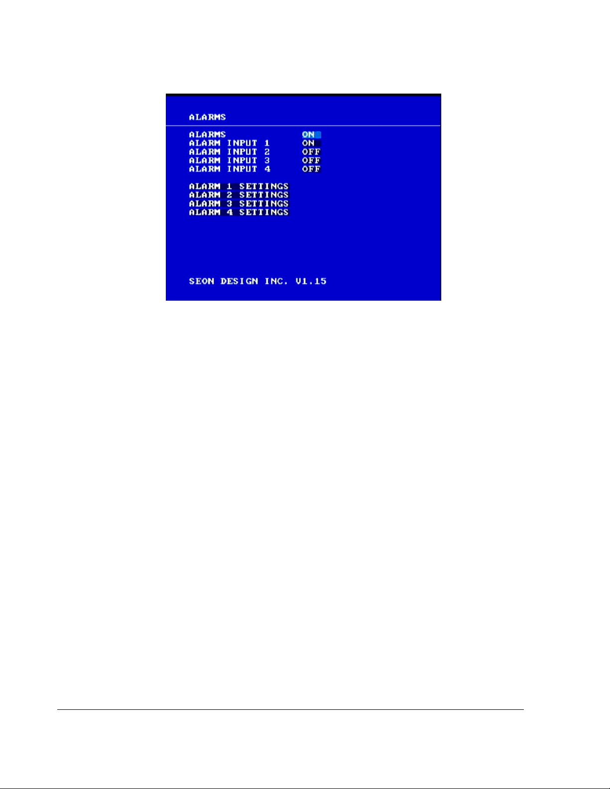
Configuring the DVR
Figure 3-6
Alarms menu
To change a setting on the sub-menu:
1. Turn the
2. Press the
3. Press the
JOG wheel clockwise or counter clockwise to change the value.
LOCK > button to advance through the fields.
DISPLAY < button to move back through the fields.
The selected menu item is highlighted with a pale blue background.
4. Press the
CLEAR button to reload the default value into a field.
5. To enter the Alarm 1 Settings to Alarm 4 Settings, press the
The Alarm 1 setting menu appears as shown in Figure 3-7.
ENTER button.
3–16 700-0048 R003
Page 55
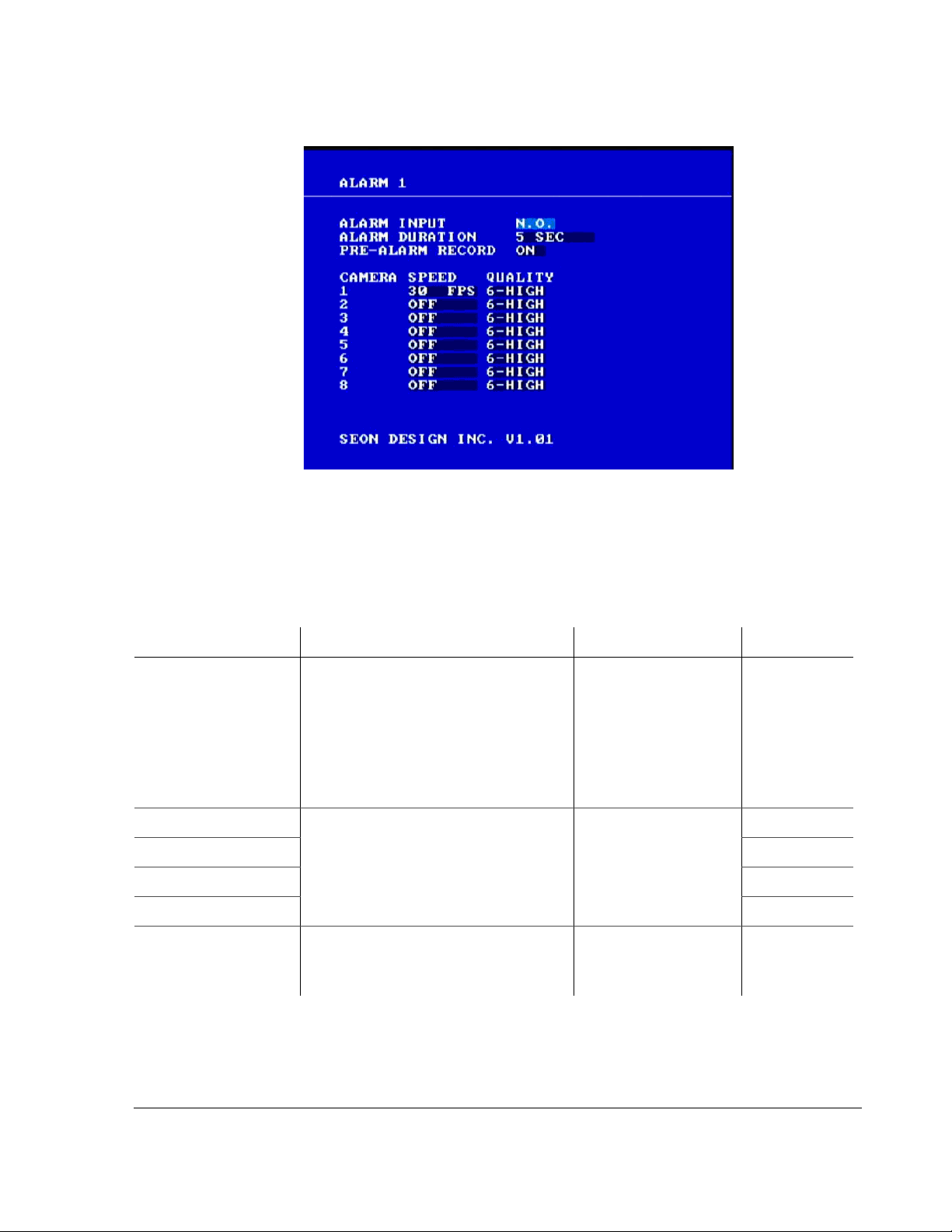
Configuring the DVR
Figure 3-7
Alarm settings sub-menu
6. Repeat these steps to set the Alarm Input, Alarm Duration, Camera Speed and
Quality. See Table 3-9.
7. To exit the menu, press the
Table 3-9
ALARMS Setting the Alarms option to ON
Alarm configuration items
Menu Item Description Values Default
allows the Alarm input options to
control the individual alarms.
Setting the Alarms option to
disable all alarms, regardless of the
settings of the alarm input options.
ALARM
ALARM
ALARM
ALARM
ALARM
ALARM 4 SETTINGS
INPUT 1 Alarm input controls the four
INPUT 2 ON
individual alarms.
INPUT 3 OFF
INPUT 4 OFF
1 SETTINGS to
Allows you to set the individual
settings duration for the four alarm
inputs.
MENU button.
OFF will
ON, OFF ON
ON, OFF ON
Presents an alarm submenu.
Not
applicable
700-0048 R003 3–17
Page 56

Configuring the DVR
Table 3-10
ALARM INPUT Alarm input option refers to the type
Alarm 1 settings configuration items
Menu Item Description Values Default
N.O. (normally open) would
of contact closure required to activate
an alarm. All of the alarm inputs are
activate an alarm when
connected to ground.
activated by a change reference to
signal ground.
N.C. (normally closed) would
normally be connected to
ground and then opened to
trigger an alarm.
ALARM DURATION The alarm duration time is the length
of time after an alarm has been
received that the video is recorded at
the alarm speed and quality. The
alarm duration is also used as a data
pointer for data access.
0, 5 SEC, 10 SEC, 15 SEC,
SEC, 1 MIN, 2 MIN, 3 MIN,
30
MIN, 5 MIN, 10 MIN,
4
15
MIN, 20 MIN, 30 MIN,
MIN, 60 MIN and NON-
45
STOP
Note: The 0 option is for
using the alarm event as a
searchable item only.
-ALARM RECORD Not applicable. Not applicable. ON
PRE
N.O.
SEC
5
3–18 700-0048 R003
Page 57

Configuring the DVR
Table 3-10
CAMERA 1 SPEED Aggregate 30 FPS at 720×480
CAMERA
CAMERA
CAMERA
CAMERA
CAMERA
CAMERA
CAMERA
Alarm 1 settings configuration items
Menu Item Description Values Default
2 SPEED OFF
3 SPEED
4 SPEED
5 SPEED
6 SPEED
7 SPEED
8 SPEED
resolution across all eight channels.
Aggregate 60 FPS at 720×240
resolution across all eight channels.
For example, 7.5 FPS for eight
cameras (7.5 FPS × 8 = 60 FPS) at
720×240 resolution.
Aggregate 120 FPS at 360×240
resolution across all eight channels.
For example, 15 FPS for eight
cameras (15 FPS × 8 = 120 FPS) at
360×240 resolution.
Usually a DVR will be recording in a
mode that conserves hard drive space,
but increases the speed and quality for
a short duration to record the alarm
event.
Note: Setting a camera speed to OFF
will cause a camera to not be recorded
during an alarm. This will allow other
cameras to be recorded at a higher
speed.
30
FPS, 20 FPS, 15 FPS, 10
FPS, 7.5 FPS, 6 FPS, 5 FPS,
4
FPS, 3 FPS, 2 FPS, 1 FPS, OFF
30 FPS
CAMERA
CAMERA 8 QUALITY
1 to
The EX8 Plus DVR uses MPEG-4
video compression to extend the
recording time on the hard drive. The
picture quality option lets you trade
off the amount a picture is
compressed versus the amount of
memory the picture takes up on the
hard drive.
Picture Quality
• 1 (Standard)
•2
•3
•4
•5
• 6 (High)
6 (High)
For example, a higher picture quality
(6) means lower compression and
therefore a higher memory
requirement. A lower picture quality
(1) means higher compression. See
Table 3-5, “Picture quality settings”
on page 3–13.
700-0048 R003 3–19
Page 58
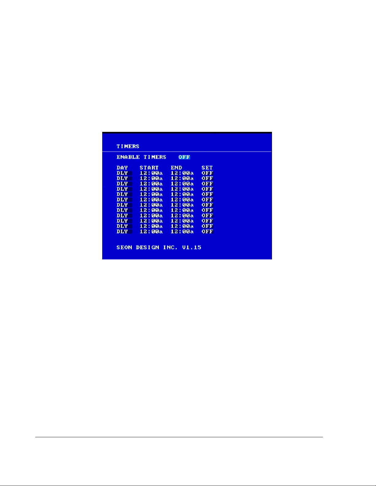
Configuring the DVR
3.2.6. Using the Timers Menu
Use the Timers menu to change the timer schedules to meet different bus route
requirements.
To view the Timers menu:
1. On the main menu, turn the
JOG wheel to highlight TIMERS.
2. Press the
ENTER button.
The Timers menu appears as shown in Figure 3-8.
Figure 3-8
Timers menu
To change a setting on the sub-menu:
1. Turn the
2. Press the
3. Press the
JOG wheel clockwise or counter clockwise to change the value.
LOCK > button to advance through the fields.
DISPLAY < button to move back through the fields.
The selected menu item is highlighted with a pale blue background.
4. Press the
5. To exit the menu, press the
CLEAR button to reload the default value into a field.
MENU button.
6. Repeat these steps to set the Enable timers, Day , Start, End, and Set. See Table
3-11.
3–20 700-0048 R003
Page 59

Configuring the DVR
Table 3-11
ENABLE TIMERS Enable Timers lets you record
Timers configuration items
Menu Item Description Values Default
at preset times during the day.
The vehicle ignition must be
turned on for the timers to
work.
Note: If the Timers are enabled
and all the individual timers are
set to
OFF, the DVR will never
start recording. Either turn on
an individual timer or set
Enable Timers to
OFF.
The Record Delay-On settings
are overridden by the timers,
except for the first 30 seconds.
If the system is recording
during a Timer interval, then
the Record Delay-Off settings
will override the timer once the
vehicle ignition is turned off.
ON, OFF (When turned ON,
the DVR will not record
unless a timer has been
turned
ON.)
OFF
DAY Set the timer to record every
day, daily, every weekday, or
only on the weekend.
START
Set the time in 12-hour or 24hour format in the
TIME/DATE
menu. Avoid overlapping the
Start and End time.
END Set the time in 12-hour or 24-
hour format.
SET Set the individual timer to ON or
OFF.
• SUN (Sunday)
MON (Monday)
•
•
TUE (Tuesday)
WED (Wednesday)
•
THU (Thursday)
•
•
FRI (Friday)
SAT (Saturday)
•
DLY (Daily)
•
•
WDAY (Weekday)
WKEND (Weekend)
•
• 12:00:00a to 11:59:59p
DLY
12:00a
• 00:00:00 to 23:59:59
• 12:00:00a to 11:59:59p
12:00a
• 00:00:00 to 23:59:59
ON, OFF OFF
700-0048 R003 3–21
Page 60
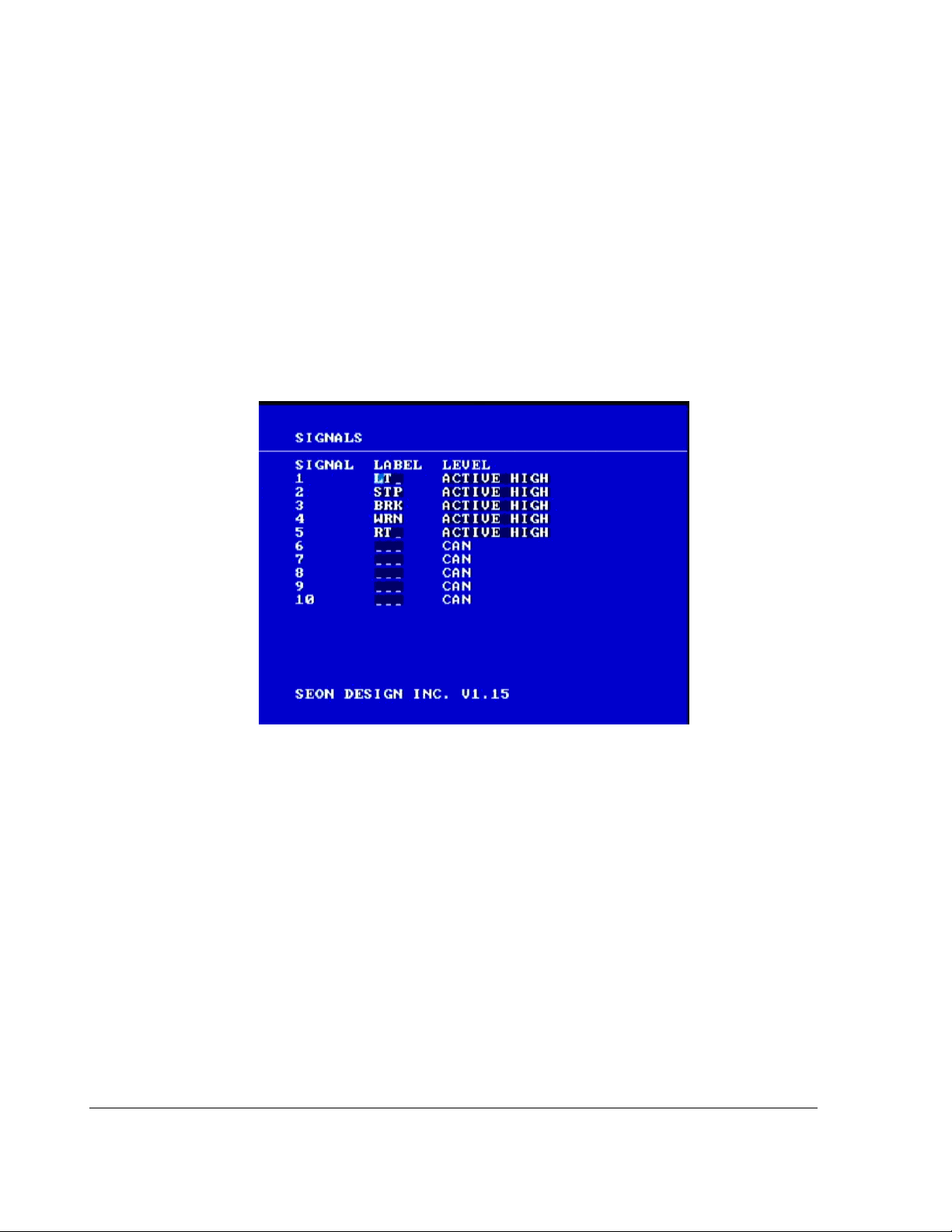
Configuring the DVR
3.2.7. Using the Signals Menu
The EX8 Plus DVR using the Smart-Link module has the ability to record various
signals from the vehicle. For example, when the brakes are applied, the text
can be recorded on the camera picture.
Use the Signals menu to configure ten different character strings to be displayed
when an external analog signal or CAN message has been sent.
To view the Signals menu:
1. On the main menu, turn the
2. Press the
The Signals menu appears as shown in Figure 3-9.
ENTER button.
BRK
JOG wheel to highlight SIGNALS.
Figure 3-9
Signals menu
To change a setting on the sub-menu:
1. Turn the
2. Press the
3. Press the
JOG wheel clockwise or counter clockwise to change the value.
LOCK > button to advance through the fields.
DISPLAY < button to move back through the fields.
The selected menu item is highlighted with a pale blue background.
4. Press the
5. To exit the menu, press the
CLEAR button to reload the default value into a field.
MENU button.
6. Repeat these steps to set the Label and Level. See Table 3-12.
3–22 700-0048 R003
Page 61

Configuring the DVR
Table 3-12
LABEL (1) LT (Left) LT
Signal configuration items
Menu Item Description Values Default
2 STP (Stop) STP
3 BRK (Brake) BRK
4 WRN (Warning lights) WRN
5 RT (Right) RT
6–10 Signals 6 to 10 are CAN signals and are defined by the user. See
No default.
“2.12. CAN Network” on page 2–16.
LEVEL Level indicates the activation
level for the signal. If
HIGH is selected, then 12 VDC
ACTIVE
ACTIVE HIGH, ACTIVE LOW
OR CAN
ACTIVE
applied to a signal will cause the
text to be displayed.
If
ACTIVE LOW is selected, then
0 VDC applied to a signal will
cause the text to be displayed.
If
CAN is selected, then a CAN
network message will cause the
signal to be activated.
HIGH
700-0048 R003 3–23
Page 62
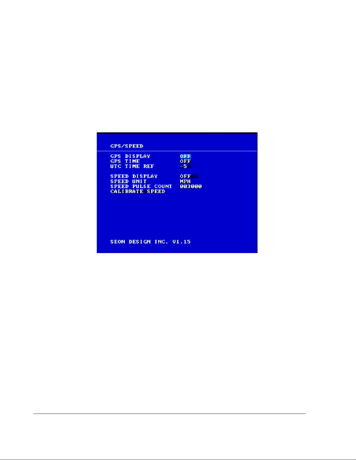
Configuring the DVR
3.2.8. Using the GPS/Speed Menu
The EX8 Plus DVR has the ability to display and record GPS data from an
external GPS receiver, as well as display and record vehicle speed from several
different sources.
To view the GPS/Speed menu:
1. On the main menu, turn the
2. Press the
The
ENTER button.
GPS/SPEED menu appears as shown in Figure 3-10.
JOG wheel to highlight GPS/SPEED.
Figure 3-10
GPS/Speed menu
To change a setting on the sub-menu:
1. Turn the
2. Press the
3. Press the
JOG wheel clockwise or counter clockwise to change the value.
LOCK > button to advance through the fields.
DISPLAY < button to move back through the fields.
The selected menu item is highlighted with a pale blue background.
4. Press the
5. Exit the menu, press the
CLEAR button to reload the default value into a field.
MENU button.
6. Repeat these steps to set the GPS Display, GPS Time, UTC Time Ref, Speed
Display, Speed Unit, Speed Pulse Count, and Calibrate Speed.
See Table 3-13.
3–24 700-0048 R003
Page 63

Configuring the DVR
Table 3-13
GPS DISPLAY When GPS DISPLAY is ON, and a GPS receiver is
GPS/SPEED configuration items
Menu Item Description Values Default
connected to the DVR, the latitude and longitude of
the vehicle location are displayed on the screen.
TIME Embedded in the GPS satellite signal is a very
GPS
accurate time source. Setting the
will synchronize the
DVR’S internal clock to the
GPS TIME to ON
GPS satellite time. Because the GPS satellites do
not know where the GPS receiver is, the GPS
signal sends Universal time, or
UTC time (also
known as Universal Time Coordinated.)
UTC
TIME REF UTC is referenced to the atomic clock standard in
Greenwich, England. The
time difference from
Eastern Standard Time is –5 hours from
Pacific Standard Time is –8 hours from
To use
from
GPS time, determine your time difference
UTC time and enter this time into the DVR. Use
the time reference to standard time. The
DVR location is a certain
UTC time. For example,
UTC time.
UTC time.
DVR will
keep track of the Daylight Saving Time changes
internally (if auto daylight saving is set to on).
ON, OFF OFF
ON, OFF OFF
–12 to + 12 in
–5
one-hour
increments
SPEED DISPLAY If speed is not being recorded, change the speed
display option to
OFF. This will turn off the 0 that
shows on the display which indicates zero speed.
If speed is being recorded, there are three sources
that the
DVR can use to obtain vehicle speed:
• a pulse counting input
GPS receiver
•a
•vehicle
CAN network.
Set the speed display option to the desired input
type. Note: All of the speed input devices are
optional. Contact your sales representative at Seon
Design to obtain the optimal speed solution.
UNIT If Speed is being recorded from the GPS receiver or
SPEED
the
CAN network, then the desired speed display
units must be selected. Selecting the speed unit to
MPH will make the DVR convert the GPS signal to
be
display speed in miles per hour.
If the speed display is set to pulse, the speed unit
does not matter as the calibration routine
automatically sets the unit.
OFF, PULSE, GPS,
CAN
MPH, KPH, KTS
(knots)
OFF
MPH
700-0048 R003 3–25
Page 64

Configuring the DVR
Table 3-13
SPEED PULSE COUNT The EX8 Plus DVR can record vehicle speed by
GPS/SPEED configuration items
Menu Item Descrip t io n Values Default
2500 to 150,000 003000
counting the number of pulses received either from
a vehicle speed sensor or a vehicle Transmission
Control Module (
TCM). The DVR must first be
calibrated to the vehicle’s speed signal by driving
for one mile (kilometer) in Calibration Mode. The
DVR counts the pulses from the vehicle’s speed
sensor and then converts a pulse rate into speed.
The actual distance driven during calibration
determines the unit of the speed. For example,
driving one mile during calibration will result in
speed being in
result in
MPH. Driving one kilometer will
KPH. The SPEED PULSE COUNT will
increment as the vehicle travels.
CALIBRATE SPEED When calibrating speed, it is best to use known
Not applicable Not
road markers to determine a mile (kilometer) as
reading the odometer may introduce errors.
To calibrate speed:
1. Press the
POWER button only once to begin calibration.
applicable
It will take approximately two seconds for the system to be ready to start
calibration. After driving one mile, the
SPEED PULSE COUNT may be anywhere
from 2500 to 150,000, depending on the type of vehicle speed sensor being
used.
2. Press the
The
POWER button again to save the calibration value.
DVR will return to the GPS/Speed menu and the new calibrated speed
pulse count will be shown.
Important:
or to set a known value from a similar vehicle. This is useful if a fleet consists of several
models of the same bus. By calibrating one bus, the speed pulse count can then be entered
into the DVRs for all of the similar buses. However, if a DVR is moved from one bus to
another, the speed may have to be recalibrated due to differences in transmissions, tires,
and other factors.
You can change the speed pulse count to either fine tune the speed display,
3–26 700-0048 R003
Page 65
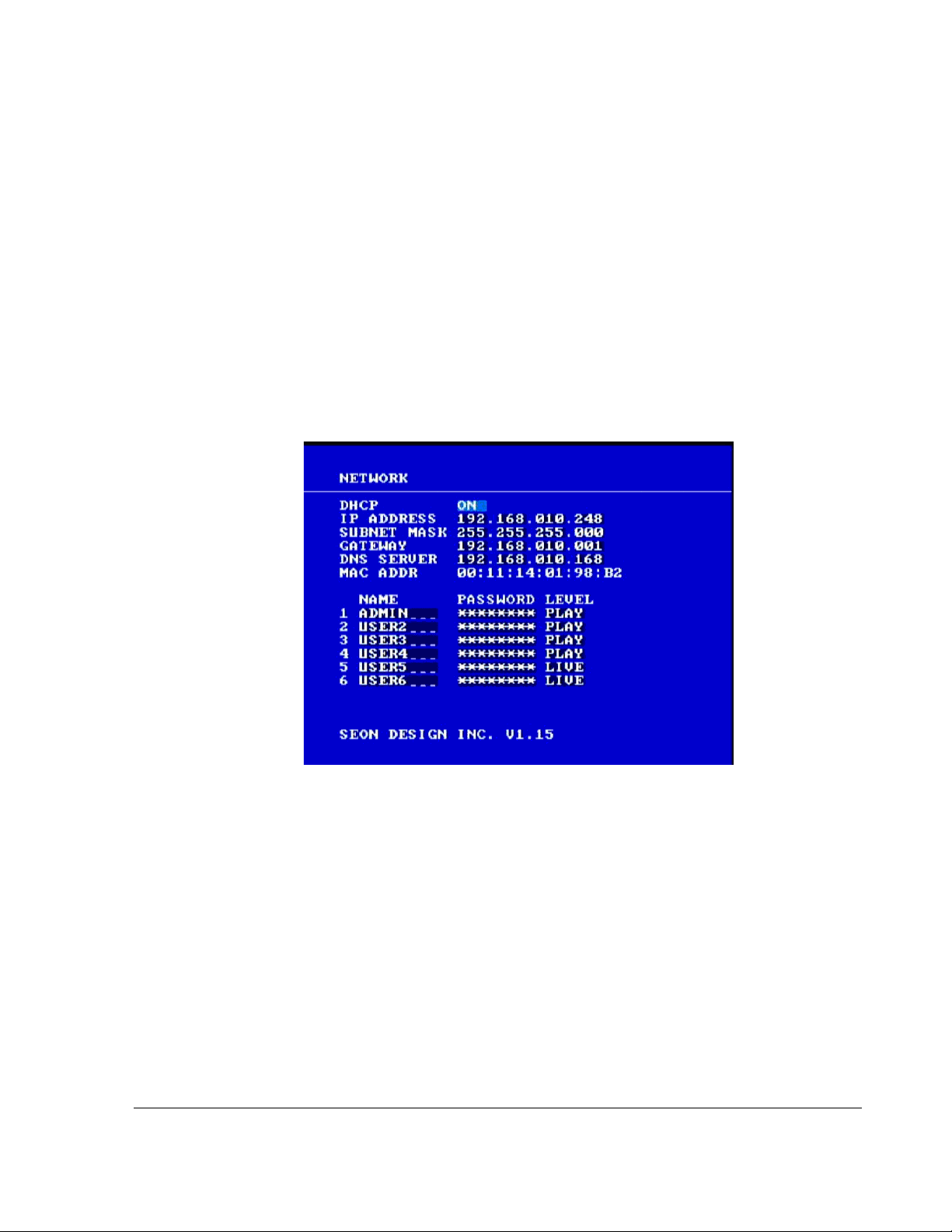
3.2.9. Using the Network Menu
The EX8 Plus DVR has a built-in network interface for connecting to an office
network or to certain peripheral devices.
Use the Network menu to set the communication parameters necessary to use the
Ethernet connection on the EX8 Plus DVR. Using the Network connection in the
DVR requires specific knowledge to which the DVR is being connected. A
qualified IT administrator will be required to provide information about the
network and assist in configuring the Network menu.
To view the Network menu:
1. On the main menu, turn the
Configuring the DVR
JOG wheel to highlight NETWORK.
2. Press the
The
Figure 3-11
ENTER button.
NETWORK menu appears as shown in Figure 3-11.
Network menu
To change a setting on the sub-menu:
1. Turn the
2. Press the
3. Press the
JOG wheel clockwise or counter clockwise to change the value.
LOCK > button to advance through the fields.
DISPLAY < button to move back through the fields.
The selected menu item is highlighted with a pale blue background.
4. Press the
5. To exit the menu, press the
CLEAR button to reload the default value into a field.
MENU button.
6. Repeat these steps to set the menu items. See Table 3-14.
700-0048 R003 3–27
Page 66

Configuring the DVR
Table 3-14
DHCP If a DHCP server is being used,
Network configuration items
Menu Item Description Values Default
ON, OFF ON
ON. To assign specific
select
network parameters for IP
Address, Subnet Mask, Default
Gateway , and DNS Server , set the
DHCP option to
IP
ADDRESS For the IP address, enter a static IP address for the DVR.
OFF.
192.168.010.248
Make sure this address is not used by any other device on
the network. If there is a DHCP server on the network,
make sure the DVR IP address is not in the IP address
range assigned by the DHCP server.
SUBNET MASK Enter the subnet mask for the network (usually
255.255.255.000
255.255.255.0).
DEFAULT GATEWAY Enter the IP address of the router or gateway on the LAN. 192.168.010.001
DNS SERVER Enters the IP address of the DNS server on the network. 192.168.010.168
MAC ADDR The MAC address is fixed in the DVR and corresponds to
Not configurable
the unique ID of the internal Ethernet controller.
USER NAME Six different user names can be assigned access to the DVR over a network. The
user names are programmable.
• User 1 Name:
ADMIN
Password: 11111111
Level:
PLAY
• Users 2 to 4 Name: USER n
Password: nnnnnnnn
Level:
PLAY
• Users 5 to 6 Name: USER n
Password: nnnnnnnn
LEVEL
There are two levels of network
access for the DVR:
LIVE.
PLAY and
PLAY allows you
•
to view recorded
video on the
DVR.
•
LIVE only lets you
see what the
DVR
Level:
•1
•2 PLAY
•2 PLAY
•4 PLAY
•5 LIVE
•6 LIVE
LIVE
PLAY
is recording.
3–28 700-0048 R003
Page 67

3.2.10. Using the System Menu
The System menu allows control of system level settings and functions that
should only be accessed by authorized individuals.
To view the System menu:
Configuring the DVR
1. On the main menu, turn the
2. Press the
The
Figure 3-12
ENTER button.
SYSTEM menu appears as shown in Figure 3-12.
System menu
JOG wheel to highlight SYSTEM.
To change a setting on the sub-menu:
1. Turn the
2. Press the
3. Press the
JOG wheel clockwise or counter clockwise to change the value.
LOCK > button to advance through the fields.
DISPLAY < button to move back through the fields.
The selected menu item is highlighted with a pale blue background.
4. Press the
5. To exit the menu, press the
CLEAR button to reload the default value into a field.
MENU button.
6. Repeat these steps to set the sub-menu items. See Table 3-15.
700-0048 R003 3–29
Page 68

Configuring the DVR
Table 3-15
Menu Item Description Values Default
ONE-TOUCH
DOWNLOAD
ALARM
VIDEO
BUZZER If set to ON, the buzzer sounds
LOSS BUZZER If set to ON, the buzzer sounds
System configuration items
Lets you use the ONE-TOUCH
button without a video
monitor. See “4.5.2. U
THE ONE-TOUCH
OWNLOAD OPTION” ON
D
PAGE 4–7.
when an external alarm is
received.
for 30 seconds if a camera
signal goes away while the
DVR is operating.
SING
ALARMS will download alarm
•
ALARMS
events only, starting with the
latest segment and working
backwards.
•
TODAY will download as much
information from today as
possible, starting with the latest
segment and working
backwards.
•
TIME will download as much
information as possible onto the
external device, starting with
the latest segment and working
backwards.
ON, OFF OFF
ON, OFF OFF
DISK
FULL BUZZER If set to ON, the buzzer sounds
REPEAT RECORD option
if the
is set to
OFF and the hard drive
ON, OFF OFF
is full.
WATERMARK
VIDEO If set to ON, an undetectable
ON, OFF OFF
code is embedded into the
video that can only be seen
using a special viewing
application.
PASSWORD
ENABLE If set to ON, the front keypad
ON, OFF OFF
will be locked out and
requires a password. Enter the
password while pressing the
FULL button. To use this
function, see “4.5.6. Using the
LOCK Button” on page 4–13.
SET
PASSWORD The password is 8 characters. Uses the numbers 0 1 2 3 4 5 6 7 8. 88888888
3–30 700-0048 R003
Page 69

Configuring the DVR
Table 3-15
LOAD DEFAULTS The EX8 Plus DVR has four
System configuration items
Menu Item Description Values Default
sets of default settings:
SEON
(the Seon factory options and
MEM1, MEM2, MEM3, one of
three settings that can be
changed by the user.
SET DEFAULTS The EX8 Plus DVR has four
sets of default programming.
The Seon defaults cannot be
changed.
The other three defaults can
be changed and saved in the
Set Defaults menu. This
means you can easily call up
different programming
features based on the use of
the vehicle.
IMPORT DEFAULTS A set of defaults can be
imported from a USB storage
device. The settings on the
USB are saved from another
EX8 Plus DVR (see Export
Defaults). This is a useful
feature if several buses in a
fleet are to be programmed all
the same.
SEON, MEM1, MEM2, MEM3 Not
applicable
MEM1, MEM2, MEM3 Not
applicable
CURRENT, MEM1, MEM2, MEM3 Not
applicable
EXPORT DEFAULTS The defaults programmed into
the DVR can be saved to an
CURRENT, MEM1, MEM2, MEM3 Not
applicable
external USB memory device.
If there are several vehicles in
the fleet that are all
programmed the same, then
the defaults can be set up on
one bus, exported using the
Export Defaults feature, and
then imported on the other
DVRs using the Import
Defaults option.
(Note: The DVR password is
not exported with the
defaults.)
700-0048 R003 3–31
Page 70

Configuring the DVR
Table 3-15
PROGRAM UPDATE The EX8 Plus DVR software can be upgraded in the field as new
System configuration items
Menu Item Description Values Default
features are added. The Program update option will make the DVR
read the new software from the USB memory device and
reprogram itself.
FORMAT HARD DRIVE Reformats the data hard drive
and makes all the previous
data inaccessible (but not
DRIVE 1 on EX8 PLUS DVR
(On the newer software, there is no
reference to
DRIVE 1.)
actually erased).
3.2.11. Updating the Software Program
The software update must be obtained from Seon Design. Attempting to load
other software will not work on the EX4 DVR.
Updating the software program on the DVR involves the following steps:
• Insert a USB memory device with new software into the USB port.
• Back up your currently used settings (Export Defaults).
• Run the program update (Program Update) and restart the DVR.
• Load the default settings (Load Defaults) and restart the DVR.
• Load the previously saved settings (Import Defaults).
• Format the hard drive (Format Hard-drive).
Not
applicable
DRIVE 1
3.2.11.1. Beginning the Software Update
To install a software update, a USB memory device must be formatted from a
Windows computer using the FAT file format. Load the Program Update file onto
the USB memory device.
To install a software program update to the EX4 DVR:
1. Make sure the DVR is powered off.
2. Unlock and remove the hard drive.
3. Power up the DVR using the vehicle ignition.
Important:
update.
Do not use temporary power mode to power up the DVR for a program
4. Insert the USB memory device with the new software version into the USB
port on the front of the DVR.
5. After the DVR has restarted, press the
MENU button.
3–32 700-0048 R003
Page 71
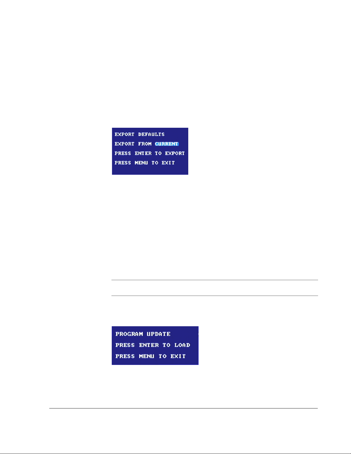
3.2.11.2. Backing up Your Currently Used Settings
This process will save your current DVR settings to the USB memory device. The
settings will be reloaded later.
To back up your currently used settings:
1. Turn the
2. Press the
JOG wheel to select SYSTEM and press the ENTER button.
LOCK > button to select EXPORT DEFAULTS and press the ENTER
button.
The Export Defaults popup menu appears, as shown in Figure 3-13.
Configuring the DVR
Figure 3-13
3. Turn the
4. Press the
Export defaults popup menu
JOG wheel to select CURRENT to export the currently used settings.
ENTER button to export.
5. The screen will display, “
OR
Press the
MENU button to exit.
3.2.11.3. Running the Program Update
This step will load the new software onto the EX4 DVR.
To run the program update:
Important:
the DVR will be corrupt.
Ensure the vehicle ignition is turned on. If power goes away in PHASE3,
1. Select Program Update in the System menu and press the
The Program Update popup menu appears, as shown in Figure 3-14.
UPLOAD........” and then “SUCCESS”.
ENTER button.
Figure 3-14
2. Press the
700-0048 R003 3–33
Program update popup menu
ENTER button.
Page 72
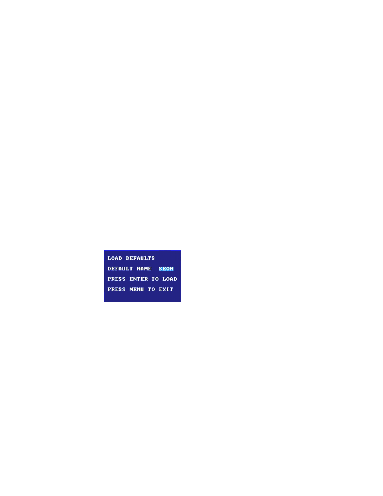
Configuring the DVR
The screen will display “PHASE1/3…” for approximately 20 seconds as it
reads the information from the USB memory device.
The screen will display “
new program is verified.
The DVR reprograms itself and displays “
seconds.
After the DVR has reprogrammed itself, the menu will go back to the
menu, and “
SUCCESS PLEASE REBOOT” will be displayed at the bottom of the
screen.
3. Remove the USB memory device.
4. Power the DVR off and restart it to finish loading the new software.
3.2.11.4. Loading the Default Settings
This step will load the default settings for the DVR to ensure that all of the new
functions have been completely initialized.
To load the default settings:
PHASE2/3…” for approximately 15 seconds as the
PHASE3/3…” for approximately 90
SYSTEM
1. Once the DVR powers up, press the
2. Turn the
3. In the
JOG wheel to highlight SYSTEM and press the ENTER button.
LOAD DEFAULTS menu, press the ENTER button.
MENU button.
The Load Defaults popup menu appears, as shown in Figure 3-15.
Figure 3-15
4. Turn the
Selecting
5. Press the
The screen will display, “
OR
Load defaults popup menu
JOG wheel to select SEON.
SEON loads Seon factory options.
ENTER button to load the default settings.
LOAD........” then “SUCCESS”.
Press the MENU button to exit the process.
6. Press the
MENU button twice to exit out of the main menu.
7. Power the DVR off and restart it.
3–34 700-0048 R003
Page 73
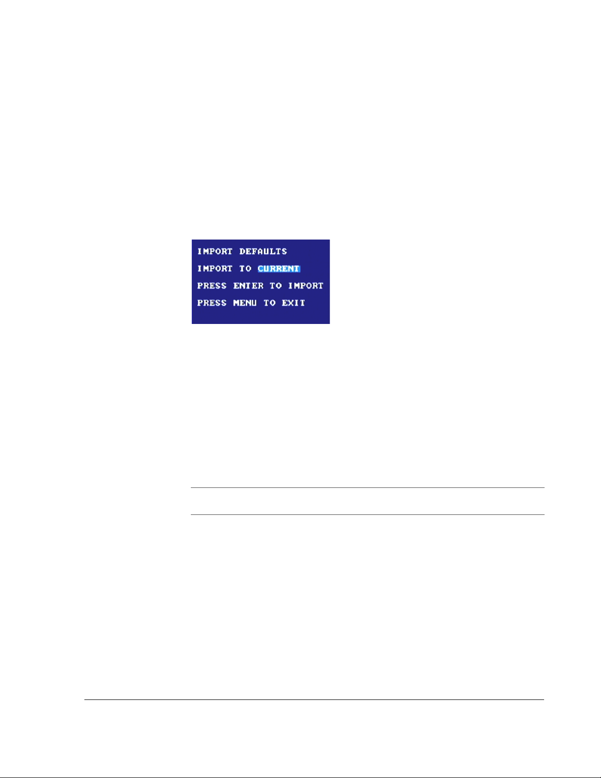
3.2.11.5. Loading the Previously Saved Settings
This step will load the previous settings saved to the USB memory device onto the
DVR.
To load the previously saved settings:
1. Insert the USB memory device.
2. Press the
MENU button.
Configuring the DVR
3. Turn the
4. In the
JOG wheel to highlight SYSTEM and press the ENTER button.
IMPORT DEFAULTS menu, press the ENTER button.
The Import Defaults popup menu appears, as shown in Figure 3-16.
Figure 3-16
5. Turn the
6. Press the
Import defaults popup menu
JOG wheel to select CURRENT to export the currently used settings.
ENTER button to import.
The screen will display, “
OR
Press the
7. Press the
MENU button to exit the process.
MENU button twice to exit out of the main menu.
3.2.11.6. Formatting the Hard Drive
LOAD.....…” then “SUCCESS”.
Important:
EX4 DVR.
The hard drives supplied by Seon Design are pre-formatted to work in the
Before formatting an existing hard drive, you may wish to create an archive file
using the HD Reader. For more information, see the HD Reader User’s Guide,
document part number 700-0036.
If a new hard drive is being used in the EX4 DVR, it should first be reformatted.
Any new hard drive that is incompatible will format automatically.
To format the hard drive:
1. Make sure a hard drive is installed and locked.
2. If necessary, press the
Wait five seconds for the DVR to stop recording and the
STOP button to stop recording.
REC button is not
illuminated.
700-0048 R003 3–35
Page 74

Configuring the DVR
3. Press the MENU button.
4. Turn the
JOG wheel to select the System menu, and press the ENTER button.
5. Press the
6. Press the
LOCK > button to select Format Hard-Drive.
ENTER button.
The Format Hard-Drive menu appears as shown in Figure 3-17.
Figure 3-17
Format hard-drive popup menu
OR
Press the
7. Press the
The screen will display the message, “
8. Press the
MENU button to exit the process.
ENTER button to begin formatting the hard drive.
FORMATTING..” and then “SUCCESS.”
MENU button twice to return to the camera view.
The DVR should start recording.
3–36 700-0048 R003
Page 75

CHAPTER 4
Operating the DVR
This chapter provides information and procedures for operating the DVR.
Page 76
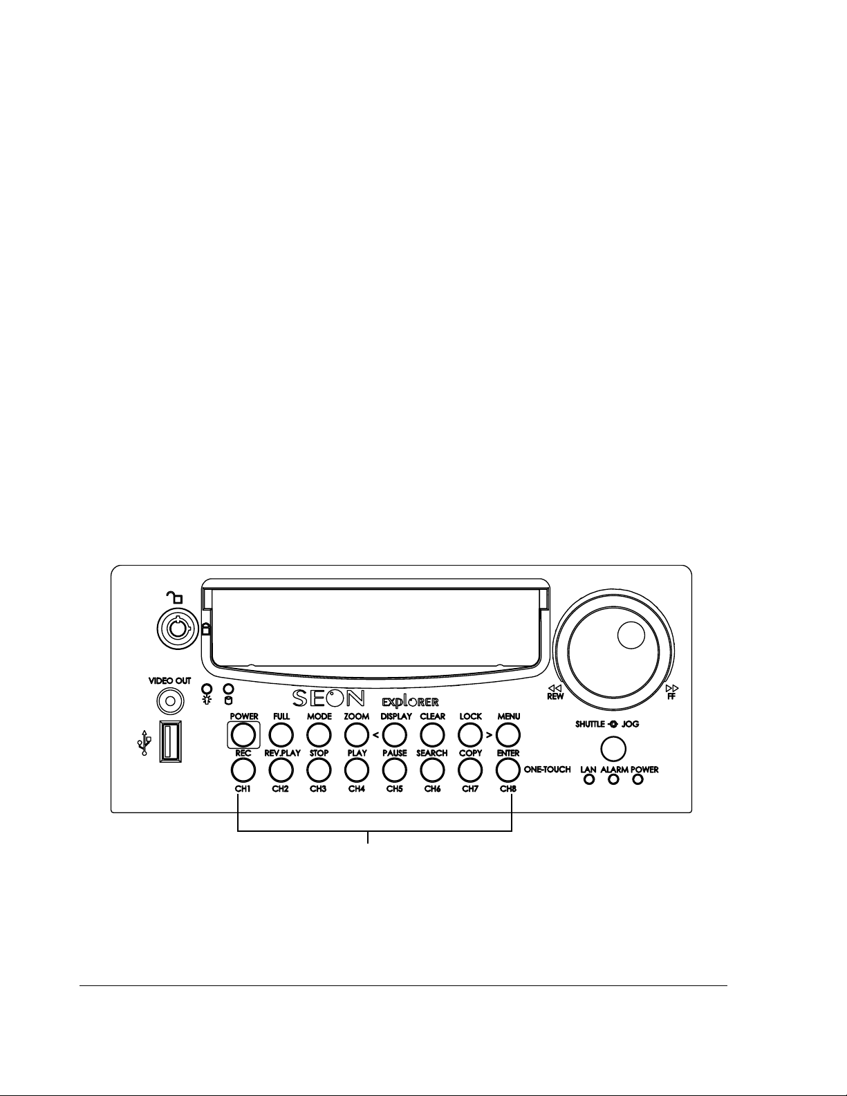
Operating the DVR
4.1. Operating and Monitoring the DVR
The EX8 Plus DVR front panel provides several features which are used to
operate and monitor the status of the DVR: DVR buttons, connectors, status
indicator light,
the indicator lights may be illuminated to show the status of the unit.
Chapter 1, “Introduction” provides an overview of the front panel features. See
Figure 1-1 on page 1–3 for an illustration of the front panel. See also Table 1-1 on
page 1–3 for a description of the functional features.
4.1.1 Using the DVR buttons
The DVR buttons are multi-function buttons. When the DVR buttons are
activated, the red LED in the centre of the button is illuminated.
Use the DVR buttons to:
• Power up the unit without turning the vehicle ignition on.
• Enter the menu mode to configure the DVR.
• Play back, stop and pause.
• Search for desired information.
• Copy information to a USB memory device.
SHUTTLE/JOG wheel. During normal operation of the DVR, any of
Figure 4-1
Use the
Front panel DVR buttons
SHUTTLE/JOG wheel to control the video playback.
Front panel DVR buttons
4–2 700-0048 R003
Page 77

Operating the DVR
Table 4-1
Button Description
POWER With the vehicle ignition turned OFF, and the DVR powered off, pressing the POWER
Using the DVR buttons
button for 3 seconds will power up the DVR, but does not initiate recording.
With the vehicle ignition turned
DELAY-OFF interval, pressing the POWER button for 5 seconds will power down the
OFF, and the DVR still powered up in the RECORD
DVR immediately. (Record Delay-Off Time enables the DVR to continue recording
after the driver has turned off the vehicle ignition. Record Delay-Off Time can be
disabled or adjusted. See “3.2.4. Using the Record Menu” on page 3–10.)
With the vehicle ignition turned
RECORD DELAY-ON interval powers up the DVR and starts recording. (Record
the
ON, pressing the POWER button for 5 seconds during
Delay-On Time determines when the EX8 Plus System will start up. Record Delay-On
Time can be adjusted. See “3.2.4. Using the Record Menu” on page 3–10.)
FULL Press the FULL button in combination with one of the eight camera buttons (CH1, CH2,
CH3, CH4, CH5, CH6, CH7, OR CH8), and the DVR will display the selected camera in full
screen display mode. If no camera is plugged in, a blue screen will be displayed.
Exit full screen display mode by pressing the
MODE Pre ss the MODE button to change the viewing display.
MODE button.
ZOOM In full screen display mode, press the ZOOM button to zoom into the screen 2×.
ZOOM button with the JOG wheel to navigate the screen. See page 4–5.
ZOOM button again to exit zoom mode and return to full screen display mode.
DISPLAY <
Use the
Press the
• Press the DISPLAY button to change the information shown on the display:
• All the information is shown.
• Removes the main title.
• Remove the camera title and DVR status display.
• Removes GPS location, speed, voltage, date and time.
• Restores all information.
While the DVR is recording in live mode, different information is displayed on the
screen. See Figure 3-1, “On-screen display during live viewing and recording” on page
3–2. Table 3-1 on page 3–2 describes the items.
<
CLEAR When configuring the DVR, pressing the CLEAR button will restore the value in the
• Press the < button to move to the previous field in menu mode when you are
configuring the DVR.
field being edited to the factory default value.
700-0048 R003 4–3
Page 78

Operating the DVR
Table 4-1
Button Description
LOCK >
Using the DVR buttons
• Press the LOCK button for three seconds in Live or Record mode to enable a OneTime password option.
>
• Press the > button moves to the next field in menu mode when you are configuring
the DVR.
MENU • Press the MENU button to enter the main menu of the DVR. The menus can be
entered in Live, Record, or Playback mode. Several program options can only be
changed when entering the menus from Live mode. For example, if the DVR is
recording and you enter the menus, the Record Quality cannot be changed. Press
the
STOP button to stop the recording and then enter to menus to change recording
parameters.
• Press the
MENU button at the main menu to exit the menu system and return to the
previous display mode and operation.
REC (CH1) • Press the REC button to start the DVR recording if the DVR is not playing video or
in the menus. When the DVR is recording, the
• Press
REV.PLAY (CH2) • During playback or when the video is stopped, press the REV.PLAY button to start
CH1 with the FULL button to select Camera 1 (CH1).
REC button is illuminated.
playing the video in reverse.
• Press
CH2 with the FULL button to select Camera 2 (CH2).
STOP (CH3) • Press the STOP button stops the DVR from recording or playing. If the DVR is
recording, pressing the
STOP button allows about five seconds before the DVR
starts recording again. During this time, you can enter the menus, start to play back
video, or copy video to the USB memory card.
• Press
PLAY (CH4) • If the DVR is not recording, press the PLAY button to start playback of the recorded
CH3 with the FULL button to select Camera 3 (CH3).
video and audio.
• Press
PAUSE (CH5) • Press the PAUSE button to pause the video playback and provide a still frame video
CH4 with the FULL button to select Camera 4 (CH4)
image.
• Press
SEARCH (CH6) • Press the SEARCH button for a power search function that lets you quickly find the
CH5 with the FULL button to select Camera 5 (CH5).
desired information. Exit the Search menu by pressing the
MENU button. See “4.5.3.
Using the Search function” on page 4–7.
• Press
COPY (CH7) • Press the COPY button to go to the Copy menu. Exit the Copy menu by pressing the
• Press
CH6 with the FULL button to select Camera 6 (CH6).
MENU button.
CH7 with the FULL button to select Camera 7 (CH7).
4–4 700-0048 R003
Page 79

Operating the DVR
Table 4-1
Button Description
ENTER/ONE-
TOUCH/(CH8)
Using the DVR buttons
• While configuring in the menu mode, the
ENTER button to navigate to the selected sub-menu.
the
• Press the
ONE-TOUCH button to start One-touch download. See “4.5.2. Using the
ENTER button acts as the ENTER key. Press
ONE-TOUCH Download option” on page 4–7.
• Press
CH8 with the FULL button to select Camera 8 (CH8).
4.2. Viewing Recorded Vi deo
To playback video:
1. If the DVR is not recording, press the
recorded video and audio.
2. During playback or when the video is stopped, press the
start playing the video in reverse.
4.2.1. Using the SHUTTLE Wheel during Playback
During playback, the SHUTTLE (outer) wheel can be used to speed up the
reviewing process. The play-speed will be displayed on the screen.
PLAY button to start playback of the
REV.PLAY button to
1. During playback, turning the
SHUTTLE wheel clockwise speeds the play
forward from 1× to 2×, 4 ×, 6 ×, 8×, 16 × and 32× the normal speed.
2. During reverse playback, turning the
SHUTTLE wheel counter clockwise
speeds the play backward from ×1 to 2×, 4 ×, 6 ×, 8×, 16 × and 32× the
normal speed.
3. When the
PAUSE button is pressed, turning the SHUTTLE wheel clockwise
reduces the play to a very slow forward rate.
4. When the
PAUSE button is pressed, turning the SHUTTLE wheel counter
clockwise reduces the play to a very slow backward rate.
This can be very useful when trying to identify the exact image where an
incident occurs.
4.2.2. Using the ZOOM Button and JOG Wheel to Adjust the Display
To adjust the display using the ZOOM button and JOG wheel:
1. Turn the
desired position.
2. Press the
3. Turn the
4. Press the
5. Repeat until the display is centered on the object of interest in both directions.
JOG wheel to shift the screen image left or right until it is in the
ENTER button.
JOG wheel to shift the screen image up or down.
ENTER button.
700-0048 R003 4–5
Page 80

Operating the DVR
4.3. Replacing the Hard Drive
The EX8 Plus DVR has a removable hard drive that is contained in a hard drive
tray . The hard drive has a lock which secures the hard drive during op eration. Use
the hard drive key to lock and unlock the hard drive.
Important:
removed when the DVR is powered up), do not remove the hard drive while the
DVR is recording as the video segment may not be recorded. Press the
button before unlocking and removing the hard drive.
To remove the hard drive:
1. Press the
2. Use the hard drive key to unlock the hard drive on the front panel.
3. Insert the hard drive key, turn counter clockwise by ¼ turn until the drive lock
is in the unlocked position.
The Hard Drive power indicator (green) will turn off.
4. Lift up on the hard drive tray handle and gently pull out the hard drive.
To install the hard drive:
1. Slide in a hard drive tray until the tray seats inside the front panel.
2. Ensure the handle is lying down against the tray.
3. Insert the hard drive key , turn clockwise by ¼ turn until the drive lock is in the
locked position.
The Hard Drive power indicator (green) will illuminate.
While the hard drive is hot-swappable, (the hard drive can be
STOP
STOP button.
4.4. Downloading Video to a PC
Downloading video to a PC is described in the Hard Drive Reader’s Manual
(document part number 700-0036). Please refer to this user guide which is
available online at www.seon.com.
4.5. Extended Operational Functions
4.5.1. Reading CAN messages
Contact Seon Design for assistance in setting up CAN messages for your DVR.
The Smart-Link module will require programming for your specific applications.
4–6 700-0048 R003
Page 81

4.5.2. Using the ONE-TOUCH Download option
Using the USB port, you have the option to download specific information to a USB
drive.
To use the O
1. In the System menu, select the
Using the System Menu” on page 3–29.
2. Insert a
NE-TOUCH download option:
ONE-TOUCH DOWNLOAD option. See “3.2.10.
USB drive into the USB port on the front panel of the DVR.
Operating the DVR
3. If the DVR is powered off, press the
POWER button for 3 seconds to power up
the DVR.
The red LED on the
MODE button or FULL button will illuminate.
OR
4. If the DVR is powered up and recording, press the
the red LED on the
ONE-TOUCH DOWNLOAD does not work while the DVR is recording.
5. Press the
ENTER/ONE-TOUCH/CH8 button.
REC button is not illuminated.
STOP button and wait until
The DVR will download the appropriate information to the
and the red LED in the
ENTER/ONE-TOUCH/CH8 button will be flashing. When
the operation is completed successfully, the red LED will turn off.
Important:
there is an error, such as a bad
6. Remove the
The red LED on the ENTER/ONE-TOUCH/CH8 will be illuminated if
USB drive or if the USB drive is full.
USB drive and power the DVR off by pressing the POWER button
for 3 seconds.
OR
7. Press the
REC button to return to recording.
USB thumb drive
4.5.3. Using the Search function
The EX8 Plus DVR includes a powerful search function that let you quickly find
recorded information by event or by time/date.
To view the Search menu:
1. If the DVR is recording, press the
to stop recording.
2. Press the
SEARCH button.
The Search menu appears as shown in Figure 4-2.
700-0048 R003 4–7
STOP button on the front panel of the DVR
Page 82
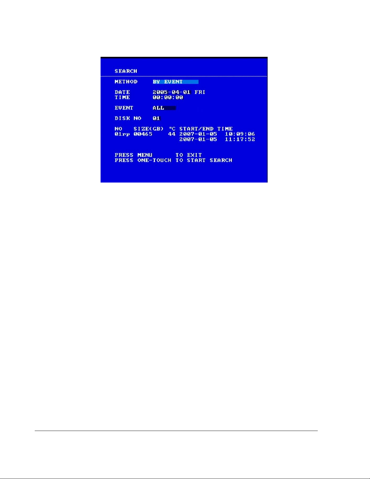
Operating the DVR
Figure 4-2
Search menu
To change a setting on the menu:
1. Turn the
2. Press the
3. Press the
JOG wheel clockwise or counter clockwise to change the value.
LOCK > button to advance through the fields.
DISPLAY < button to move back through the fields.
The selected menu item is highlighted with a pale blue background.
4. Press the
5. To exit the menu, press the
ONE-TOUCH button to start search.
MENU button.
4.5.3.1. Searching for Recording Information BY EVENT
If
BY EVENT is chosen, the DATE and TIME fields cannot be changed.
See Table 4-3.
To search for recorded information
BY EVENT:
1. Choose the Event type.
2. Press the
ONE-TOUCH button to bring up a list of events, which includes both
alarms and regular recordings.
3. Turn the
SHUTTLE wheel clockwise or counter clockwise to view the next or
previous page of events.
4. To move through the list of events line by line, turn the
or counter clockwise.
5. To search for a specific page number, press the
option to go to another page of events.
6. Turn the
JOG wheel to change the page numbers, and then press the ENTER
button to go to that page.
JOG wheel clockwise
SEARCH button to bring up the
4–8 700-0048 R003
Page 83

Operating the DVR
7. When the desired event has been chosen, press the ONE-TOUCH button to
begin playing that event.
Several different types of events may be listed. Table 4-2 describes these
events.
Table 4-2
Event Description
Event types
N (Normal) A normal recording session, started with the
vehicle ignition.
T01–T12 (Timer 1 to 12) Recording controlled by an internal timer
A01(Alarm 1) An alarm event triggered by Alarm 1.
A02 (Alarm 2)
A03 (Alarm 3,
Alarm events triggered by Alarms 2, 3, or 4,
available with EX8 Plus DVR only.
A04 (Alarm 4)
PL (Power loss) Similar to an alarm event, triggered by the
unexpected loss of power to the DVR.
Video loss Triggered by the loss of a camera signal.
RN Recording after a power loss.
4.5.3.2. Searching for Recorded Information BY TIME/DATE
BY TIME/DATE is chosen, the Event field cannot be changed.
If
To search for recorded information
1. Enter the desired
2. Press the
ONE-TOUCH button to begin playing from that time and date (or the
DATE and TIME.
BY TIME/DATE:
closest recorded video after that time and date).
3. Turn the
SHUTTLE wheel clockwise or counter clockwise to view the next or
previous page of events.
4. To move through the list of events line by line, turn the
or counter clockwise.
5. To search for a specific page number, press the
option to go to another page of events.
6. Turn the
JOG wheel to change the page numbers, and then press the ENTER
button to go to that page.
7. When the desired event has been chosen, press the
begin playing that event.
JOG wheel clockwise
SEARCH button to bring up the
ONE-TOUCH button to
700-0048 R003 4–9
Page 84

Operating the DVR
4.5.3.3. Search Menu Configuration Items
Table 4-3
Menu Item Description Values Default
METHOD BY EVENT is one of the two options for
Search menu configuration items
BY EVENT, BY TIME/DATE BY EVENT
searching.
• If
BY EVENT is selected, then the
EVENT field is active and the DATE
and
TIME fields are inactive.
BY TIME/DATE is selected, then
• If
EVENT field is inactive.
the
DATE
Set the date. MM-DD-YYYY XXX
XXX is the 3-letter symbol
(
Not
applicable
for day of the week, for
example
FRI for Friday)
• 01 to 12 for month
• 01 to 31 for day
• 2000 to 2037 for year
TIME Set the time. • 0 to 23 for 24 hour
format
Not
applicable
• 12 A.M. to 1 p.m. for 12
hour format
EVENT Set the event field. ALARM, V. LOSS, ALL ALARM
VIDEO
LOSS Shows a sea rchable event list of the
event number, type of event, date and
Not configurable. Not
applicable
time when camera signal was lost.
DISK NO The DISK NO field only allows the ‘01’
01 01
option.
4–10 700-0048 R003
Page 85
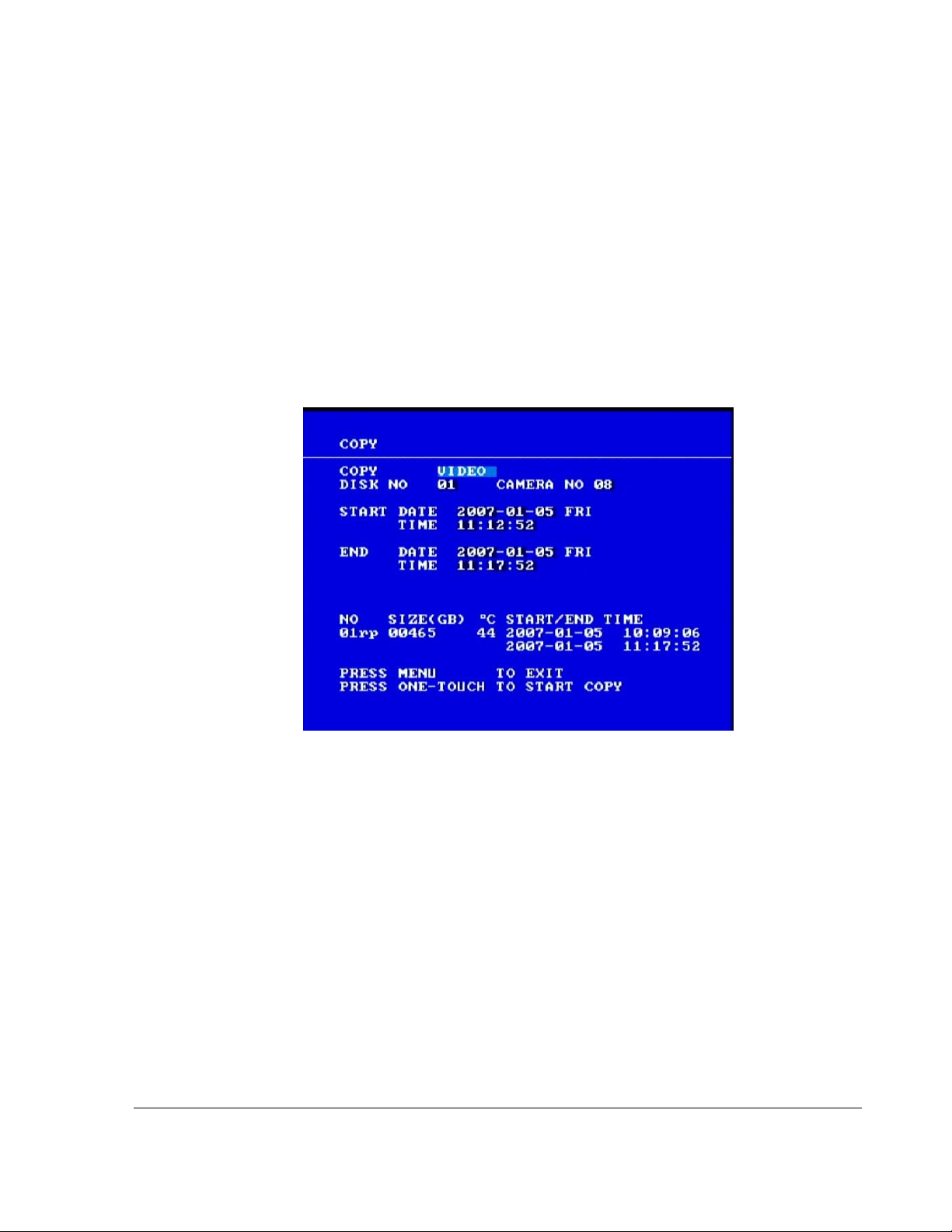
4.5.4. Using the Copy Menu
The EX8 Plus DVR can save information to a USB memory device.
To copy:
Operating the DVR
1. Insert a
USB drive that has sufficient free space into the USB port on the front
panel of the DVR.
2. If the DVR is in Live mode, press the
3. If the DVR is recording, press the
COPY button.
STOP button on the front panel of the DVR
to stop recording.
4. Press the
COPY button.
The Copy menu will appear as shown in Figure 4-3.
Figure 4-3
Copy menu
To change a setting on the menu:
1. Turn the
2. Press the
3. Press the
JOG wheel clockwise or counter clockwise to change the value.
LOCK > button to advance through the fields.
DISPLAY < button to move back through the fields.
The selected menu item is highlighted with a pale blue background.
4. Press the
5. To exit the menu, press the
700-0048 R003 4–11
ONE-TOUCH button to start search.
MENU button.
Page 86

Operating the DVR
Table 4-4
Menu Item Description Values Default
COPY The first option lets copy either VIDEO
Copy menu configuration items
information from the DVR, or
download a small
VIEWER program has very limited
VIEWER program. The
VIDEO
VIEWER
VIDEO
functionality and is designed for quick
diagnosis of the video information. It is
recommended that the Hard Drive
Reader program be used to view video
from the DVR.
NO The DISK NO field only allows the ‘01’
DISK
01 01
option.
CAMERA NO The CAMERA NO option lets you pick
1 to 8 04
the camera from which the video will be
saved to the USB memory device
START DATE The START DATE and START TIME, as
well as the
END DATE and END TIME
select the length of time to be saved to
the USB memory device. Long video
segments may take a considerable
amount of time to copy to the USB
memory device. The size of the video
file is dependent on the Quality, Speed,
and Resolution of the recorded video.
MM-DD-YYYY XXX
(
XXX is the 3-letter
symbol for day of the
week, for example
FRI
for Friday)
• 01 to 12 for month
• 01 to 31 for day
• 2000 to 2037 for
year
TIME • 0 to 23 for 24 hour
format
• 12 A.M. to 1 p.m.
for 12 hour format
END DATE MM-DD-YYYY XXX
XXX is the 3-letter
(
symbol for day of the
week, for example
FRI
for Friday)
• 01 to 12 for month
• 01 to 31 for day
• 2000 to 2037 for
year
TIME • 0 to 23 for 24 hour
format
• 12 A.M. to 1 p.m.
for 12 hour format
4–12 700-0048 R003
Page 87

4.5.5. Turning the Buzzer Off
The DVR has a built-in alarm buzzer that can be activated under certain warning or
alarm conditions. The alarm buzzer settings can be configured in the
more information, see “3.2.10. Using the System Menu” on page 3–29.
To turn the buzzer off:
1. Press the
ENTER button to silence the buzzer.
2. Check your configuration settings in the
have been set to
ON.
4.5.6. Using the LOCK Button
The front keypad on the DVR can be manually locked or unlocked by using the LOCK
button or by changing the Password Enable settings in the System menu. See “3.2.10.
Using the System Menu” on page 3–29.
Operating the DVR
SYSTEM menu. For
SYSTEM menu to see which buzzer settings
If the Password Enable option is set to
and pressing the
LOCK button will have no affect.
ON (enabled), the front keypad will be locked out
This will work in Live mode, Record mode or Alarm Record mode.
4.5.6.1. Locking out the front panel keypad
To lock out the front panel keypad if the Password Enable option is
1. Press the
The red LED on the
2. To disable the lock, enter the password while pressing the
The red LED on the
LOCK button for 3 seconds.
LOCK button will be illuminated.
FULL button.
LOCK button will not be illuminated.
4.6. Voltage Display
The EX8 Plus System displays and records the input voltage of the vehicle
on-screen. This can be a very helpful tool if problems are encountered with low voltage
vehicle power supplies.
If the voltage to the DVR is too low , the quality of the video signal from the camera wil l
be very poor, resulting in a poor recording.
4.7. Low Voltage and Low/High Temp Indicator
OFF:
In addition to the on-screen voltage display, the EX8 Plus DVR has a LOW VOLTAGE/
LOW/HIGH TEMP indicator on the back of the DVR. The indicator illuminates when the
voltage level to the DVR is too low, as shown in Table 4-5.
700-0048 R003 4–13
Page 88

Operating the DVR
Table 4-5
Voltage level to DVR
LOW VOLTAGE/LOW/HIGH TEMP indicator
LOW VOLTAGE/LOW/HIGH TEMP
indicator will … Status of the DVR
Below 10.5 VDC Illuminate The DVR will stop recording and begin to shut
down as the voltage is too low to operate the
camera properly.
Rises to 11 VDC Turn off The DVR operation will return to normal.
Smart-Link
voltage
indicator
The Smart-Link module also has a voltage indicator, which works differently than the
LOW VOLTAGE/LOW/HIGH TEMP indicator on the DVR. For the Smart-Link, the green
POWER ON/LOW VOLTAGE indicator will be illuminated when the DVR is powered up
and the operating voltage is above 10.5 VDC. When the voltage falls below 10.5 VDC,
the indicator will flash once every 2 seconds. If the voltage falls below 7.5 VDC, the
indicator will flash quickly (about twice per second) and the DVR will turn off the power
to any attached peripherals (such as a GPS module or the driver’s indicator panel).
The
LOW/HIGH TEMP indicator also illuminates according to the temperature inside the
DVR. These settings are described in “4.8. Advanced Smart-Temp”.
4.8. Advanced Smart-Temp
The EX8 Plus System incorporates several advanced features not found in any other
system on the market such as the Advanced Smart-Temp™. Advanced Smart-Temp and
the built-in heater ensure safe operation of the DVR over a wide temperature range.
Advanced Smart-Te mp monitors the temperature inside the DVR to ensure the hard
drive operates in a safe environment. In many areas, the temperature drops well below
40°F (4°C) and quite often below 32°F (0°C). Most computer hard drives are designed to
work from about 40°F (4°C) to about 120°F (49°C).
Table 4-6
Temperature inside
DVR
Below 40°F (5°C) Turns on the internal heater and pulses the
Below 5°F (–15°C) Will not power the DVR at all, although the
Advanced Smart-Temp features
Advanced Smart-Temp…
system fan to circulate the warm air.
hard drive can still be removed from the DVR.
LOW/HIGH TEMP Indicator
status
Flashes to indicate that the
temperature is too low.
Flashes to indicate that the
temperature is too low.
Above 113°F (45°C) Turns on the system fan. Flashes to indicate that the
temperature is too high.
Above 140°F (60°C) Shuts down the DVR to protect the hard drive
from damage. The system fan will continue to
Flashes to indicate that the
temperature is too high.
operate.
4–14 700-0048 R003
Page 89

CHAPTER 5
Maintenance and Returning Product for Service
This chapter provides information and procedures for performing periodic
maintenance on the EX8 Plus System and returning any part of the system
for service.
Page 90
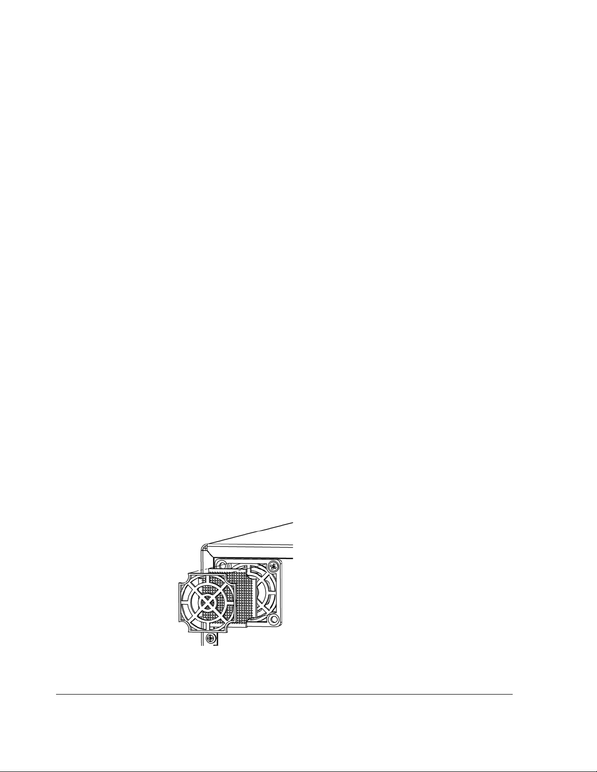
Maintenance and Returning Product for Service
5.1. Maintenance
5.1.1. Cleaning the Lock Box
The EX8 Plus System lock box is made from 18 gauge steel, coated with an
outdoor powder paint and only requires periodic cleaning. To clean the lock box,
use a damp cloth with a mild detergent. Do not allow water into the ventilation
holes on the lock box.
5.1.2. Cleaning the Camera and Window
The camera has a powder painted stainless steel enclosure. To clean the camera
enclosure, use a damp cloth with a mild detergent.
To clean the camera window, use a soft, cle an cloth to avoid scratching the
window.
5.1.3. Replacing the Fan Filter
Depending on the operating environment, the fan filter on the back of the DVR
enclosure may need to be changed occasionally. Check the filter monthly for
excess dirt and replace the filter when it restricts airflow. Failure to replace a
blocked filter may result in the DVR shutting down on a hot day due to inadequate
air circulation.
If you need a new fan filter, contact your dealer or Seon Design to obtain a
replacement.
To replace the fan filter:
1. Remove the filter cover by gently prying it off with a small flat screwdriver.
2. Discard the used filter and place a new filter back into the filter holder.
3. Push the filter cover back into the holder and snap it into place.
Figure 5-1
5–2 700-0048 R003
Replacing the fan filter
Page 91

Maintenance and Returning Product for Service
5.2. Returning Product for Service
If any part of the EX8 Plus System is to be returned to Seon Design Inc. for
service, please contact Seon, provide the model or serial number of your unit, and
ask for a Return Authorization (RA) number. An RA number allows the service
technicians to better track your product when it comes in for service. Please have
the RA number clearly marked on the outside of the shipp ing bo x.
SENT TO SEON DESIGN INC. WITHOUT AN RA NUMBER MAY BE REFUSED.
The contact numbers for Seon Design Inc. are:
ANY PRODUCT
Toll Free Telephone
Direct Telephone
1.877.630.7366
604.941.0880
Please refer to the “SEON DESIGN™ INC. PRODUCT WARRANTY” on
page W–1 to review the terms of warranty service, contact and shipping
information, as well as other important issues regarding the service and operation
of your system.
700-0048 R003 5–3
Page 92

5–4
Page 93

CHAPTER 6
Troubleshooting
This chapter provides information and procedures on troubleshooting the
EX8 Plus System.
Page 94

Troubleshooting
6.1. Troubleshooting the EX8 Plus System
The EX8 Plus System is designed for high reliability of operation. If, however,
you have any problems with your system, read this Troubleshooting chapter. If
you cannot resolve the issue, contact Customer Service at Seon Design.
Symptom Possible Cause and Solution
All problems. Many system problems are caused by issues with the power
supplied to the DVR. Check the following:
• The voltage to the system may be too low. Check the
OLTAGE indicator on the back of the DVR. See “Back
V
panel” on page 1–7 for location of the
LOW VOLTAGE
LOW
indicator.
• The power harness from the DVR must be connected as
close to the battery as possible. Check the wiring to the
battery . See “2.6. Step 5: Connecting the Ignition Harness,
Power Harness, Fuses and Fuse Holders” on page 2–9.
• Check the in-line fuses and fuse holders. If a fuse is
blown, determine the cause before replacing it.
The DVR does not power on. • Is the internal temperature below 40°F (4°C)? Check the
flashing Low Temperature indicator on the back panel of
the DVR. The DVR temperature must be above 40°F to
operate. The DVR internal heater can help to quickly raise
the internal temperature of the DVR.
• Are the power and ignition harnesses plugged into the
DVR securely?
The DVR turns on but does not start
recording.
• Check the ignition wiring from the power input harness. Is
the yellow wire connected to an ignition switched circuit.
• Is the hard drive installed properly with the key in the
locked position on the front panel?
• Is the temperature below 40°F? Check the flashing Low
Temperature indicator on the back of the DVR. Wait for
the DVR to warm up and start recording.
• Is the temperature above 122°F (50°C)? Check the
flashing
LOW TEMPERATURE indicator on the back of the
DVR. Check the fan filter on the back panel for any
blockage. If necessary, replace the fan filter. See “5.1.3.
Replacing the Fan Filter” on page 5–2.
• Check the battery voltage.
• Check the settings for Record Delay-On time in the
Record menu. See “3.2.4. Using the Record Menu” on
page 3–10.
• Are the timers on?
6–2 700-0048 R003
Page 95

Symptom Possible Cause and Solution
Troubleshooting
There is no picture on the video monitor
output.
• Check the connections inside the camera, as well as the
connections inside the DVR lock box.
•Is the
LOW VOLTAGE indicator on the back panel
illuminated?
The live camera picture is snowy, fuzzy,
or grainy.
• Check all connections inside the camera.
• Is the camera cable damaged?
• Check the connections inside the DVR lock box.
• Is the DVR power harness connected directly to the bus
battery?
The playback picture is snowy , fuzzy, or
grainy.
• Is the power input harness connected to the battery?
• Check the video monitor cable attached to the front or
back of the DVR.
No audio on playback. • Is the sensitivity adjustment on the audio module in the
camera turned down too low?
• Is the camera cable wired correctly to the terminal blocks
inside the camera?
• Is the camera connector damaged or not plugged into the
DVR securely?
• Is the record audio feature disabled?
Buzzer is sounding. • Press the
ENTER button on the front panel of the DVR.
Check to determine what caused the buzzer to sound and
clear the problem.
700-0048 R003 6–3
Page 96

6–4
Page 97

Appendix A
Specifications
This appendix provides the product specifications for the Explorer EX8 Plus
Mobile Digital Video Recording (DVR) System.
Note: Specifications are subject to change without notice.
Page 98

Specifications
A.1. EX8 Plus DVR
Video Input/Output 75 Ohm NTSC video
Video Resolution 720×480, 720×240, 360×240 p ixels
Video Compression MPEG-4
Hard Drive Style Single 2.5" or 3.5"
Hard Drive Size 40 GB to 750 GB
Hard Drive Removal Hot swappable, locking key-secured
Camera Input Connector 8 × 6-pin mini DIN connectors
Audio Input Level –8 dBm
Audio Output Level –6 dBm, 10 kOhm
Operating Temperature –4°F to 122°F (–20°C to 50°C)
Non-operating Temperature –22°F to 158°F (–30°C to 70°C)
Operating Humidity 90% relative humidity, non-condensing
Operating Voltage 11 to 17 VDC
Transient Protection 1500 W
Temperature Protection Advanced Smart-Temp
Ingress Protection IP 53
Ignition Harness Connector 2-pin Molex®
Power Harness Connector 2-pin Molex
Alarm Input Connector 2-pin Molex
Network Connector 8-pin RJ-45 Ethernet
Dimensions (H × W × D) 3.75 × 8.5 × 12.5" (95 × 216 × 318 mm)
Weight 7 lb (3.2 kg)
with SCT-LD brackets 8.5 lb (3.85 kg)
Power Circuit Fuse 10 A
Ignition Circuit Fuse 1 A
A–2 700-0048 R003
Page 99

A.2. DVR Functional Features
Time Format 12 Hour or 24 Hour mode
Specifications
Date Format
Daylight Saving Time ON (Automatic) and OFF, Programmable Start and
Main Title 24 characters
Camera Titles 12 characters per camera
Repeat Record User selectable
Record Delay-On 0 seconds to 60 mi nutes
Record Delay-Off 0 seconds to 60 minutes
Power Delay-Off 0 minutes to 255 minutes
Daily Timers 12
Alarm Input 1, User selectable
Playback Search Time/Date, Alarm, or Event
Playback Speed Image-by-Image, 2×, 4×, 6×, 8×, 16×, 32×
USB Memory Device SanDisk Cruzer® Mini or equivalent
MM/DD/YYYY, DD/MM/YYYY and YYYY/MM/DD
Stop
ON/OFF
ON/OFF with variable recording
speed, Image Quality and Alarm Duration
A.3. Additional Features of the EX8 Plus DVR
Signal Inputs 10
GPS Input Latitude, Longitude, Vehicle Speed and UTC time
Alarm Input U ser Selectable
speed, image quality and alarm duration
Speed Input Pulse counting, GPS or CAN network
Driver’s Indicator Panel Indicates DVR power status, recording status
CAN Network 10 signal inputs, factory configurable
700-0048 R003 A–3
ON/OFF with variable recording
Page 100

Specifications
A.4. Lock Box
Main Enclosure 18 GA cold rolled steel (CRS)
Enclosure Brackets 18 GA CRS
Coating Outdoor polyester powd er paint, black
Tray Slide Rails Industrial UHMW-PE
Door Lock Industrial cam lock, keyed alike. Different keying
Dimensions (H × W ×D) 4.5 × 12 × 15" (114 × 305 × 380 mm)
Weight 8 lb (3.6 kg)
A.5. Smart-Link™ Module
Power Harness Connector 4-pin Molex
available.
Auxiliary Power Output
Connector
GPS Input Connector 4-pin Molex
Signals Connector 6-pin Molex
CAN bus Network Connector 4-pin Molex
Serial Port/GPS 9-pin DB9
Alarm Input Connector 8-pin Molex
Indicator Panel Connector 5-pin Molex
Speed Input Connector 3-pin Molex
Dimensions (H × W ×D) 5.875 × 3.25 × 0.875" (150 ×83 × 23 mm)
Weight 5.6 oz (160 g)
Material 14 GA aluminium, anodized black
2-pin Molex
A–4 700-0048 R003
 Loading...