

Page 1
*700-0190*
Document Number 700-0190 R002
Page 2

Page 3
About This Guide
The User Guide is intended for anyone who needs to operate, configure, or troubleshoot the Explorer®
DX-HD Mobile Digital Video Recording (DVR) System. Related user guides include:
• Explorer DX-HD Install and Setup Guide, 700-0189
• vMax Commander Install and Setup Guide, 700-0100
• vMax Commander User Guide, 700-0120
• vMax View User Guide, 700-0137
• vMax View Quick Archiving Guide, 700-0037
Conventions Used
CAUTION
Cautions identify conditions or practices that could result in damage to the unit or other equipment, or data loss.
Recommendation: These notes provide tips for optimum performance of the DVR system.
Important: These notes provide important information, which are not as serious as a Caution.
Abbreviations and Acronyms
Acronym Definition Acronym Definition
DVR Digital video recorder IR Infrared
FPS Frames per second LAN Local area network
GPS Global Positioning System MJPEG Motion Joint Photographic Experts Group
HD High Definition OSD On-Screen Display
HDD Hard disk drive RA Return Authorization
H.264 Video compression standard TCP/IP Transmission Control Protocol/Internet Protocol
IPS Images per second USB Universal Serial Bus
UTC Universal Time Coordinated
More Information at www.seon.com
You can find more information about Seon Design Inc. as well as its products and services at
www.seon.com.
700-0190 R002 i
Page 4

ii 700-0190 R002
Page 5

Contents
Chapter 1 Introduction
1.1. Overview - - - - - - - - - - - - - - - - - - - - - - - - - - - - - - - - - - - - - - - - - - - - - - - - - - - - - - - - - - - - - - -1–2
1.2. DX-HD DVR Product Features- - - - - - - - - - - - - - - - - - - - - - - - - - - - - - - - - - - - - - - - - - - - - - - -1–3
1.2.1. DX-HD System Components - - - - - - - - - - - - - - - - - - - - - - - - - - - - - - - - - - - - - - - - - - - - - - - - - - - - -1–4
1.2.2. Recording Capacity for DVR Hard Drive Storage - - - - - - - - - - - - - - - - - - - - - - - - - - - - - - - - - - - - - - -1–4
1.2.3. Front Panel Features - - - - - - - - - - - - - - - - - - - - - - - - - - - - - - - - - - - - - - - - - - - - - - - - - - - - - - - - - - -1–5
1.2.4. Back Panel Features - - - - - - - - - - - - - - - - - - - - - - - - - - - - - - - - - - - - - - - - - - - - - - - - - - - - - - - - - - -1–7
1.2.5. Using the Trackball Mouse - - - - - - - - - - - - - - - - - - - - - - - - - - - - - - - - - - - - - - - - - - - - - - - - - - - - - - -1–8
1.3. DVR Video Configuration Playback and Archiving - - - - - - - - - - - - - - - - - - - - - - - - - - - - - - - - - -1–9
Chapter 2 DVR Operation
2.1. Remove and Replace the DVR Hard Drive - - - - - - - - - - - - - - - - - - - - - - - - - - - - - - - - - - - - - - -2–2
2.2. Search, Playback, and Archive Video - - - - - - - - - - - - - - - - - - - - - - - - - - - - - - - - - - - - - - - - - - -2–2
2.3. vMax View and DVR Hard Drive Interface- - - - - - - - - - - - - - - - - - - - - - - - - - - - - - - - - - - - - - - -2–3
2.4. On-Screen Display Access - - - - - - - - - - - - - - - - - - - - - - - - - - - - - - - - - - - - - - - - - - - - - - - - - -2–4
2.5. Playback Menu Access - - - - - - - - - - - - - - - - - - - - - - - - - - - - - - - - - - - - - - - - - - - - - - - - - - - - -2–6
2.5.1. Using the Search Function - - - - - - - - - - - - - - - - - - - - - - - - - - - - - - - - - - - - - - - - - - - - - - - - - - - - - - -2–8
2.5.2. Using the Archive Function - - - - - - - - - - - - - - - - - - - - - - - - - - - - - - - - - - - - - - - - - - - - - - - - - - - - -2–11
2.5.3. Copy to USB - - - - - - - - - - - - - - - - - - - - - - - - - - - - - - - - - - - - - - - - - - - - - - - - - - - - - - - - - - - - - - -2–13
2.6. Using One-Touch Download - - - - - - - - - - - - - - - - - - - - - - - - - - - - - - - - - - - - - - - - - - - - - - - - 2–14
Chapter 3 vMax Web Remote Operation
3.1. System requirements - - - - - - - - - - - - - - - - - - - - - - - - - - - - - - - - - - - - - - - - - - - - - - - - - - - - - -3–1
3.2. Accessing vMax Web - - - - - - - - - - - - - - - - - - - - - - - - - - - - - - - - - - - - - - - - - - - - - - - - - - - - - -3–2
3.3. vMax Web User Interface - - - - - - - - - - - - - - - - - - - - - - - - - - - - - - - - - - - - - - - - - - - - - - - - - - -3–4
3.3.1. vMax Web Live Tab - - - - - - - - - - - - - - - - - - - - - - - - - - - - - - - - - - - - - - - - - - - - - - - - - - - - - - - - - - -3–5
3.3.2. vMax Web Configuration Tab - - - - - - - - - - - - - - - - - - - - - - - - - - - - - - - - - - - - - - - - - - - - - - - - - - - - -3–6
3.3.3. vMax Web Playback Tab - - - - - - - - - - - - - - - - - - - - - - - - - - - - - - - - - - - - - - - - - - - - - - - - - - - - - - - -3–7
3.3.1. vMax Web Archive Tab - - - - - - - - - - - - - - - - - - - - - - - - - - - - - - - - - - - - - - - - - - - - - - - - - - - - - - - -3–12
3.3.2. Viewing DX-HD Video Archives - - - - - - - - - - - - - - - - - - - - - - - - - - - - - - - - - - - - - - - - - - - - - - - - - -3–13
Chapter 4 DVR Firmware and Configuration Uploads
4.1. Firmware Updates- - - - - - - - - - - - - - - - - - - - - - - - - - - - - - - - - - - - - - - - - - - - - - - - - - - - - - - - -4–2
4.2. Configuration Uploads- - - - - - - - - - - - - - - - - - - - - - - - - - - - - - - - - - - - - - - - - - - - - - - - - - - - - -4–3
4.2.1. USB Memory Device to DVR Configuration Upload - - - - - - - - - - - - - - - - - - - - - - - - - - - - - - - - - - - - -4–3
4.2.2. Uploading Configuration Files to DVR via vMax Web - - - - - - - - - - - - - - - - - - - - - - - - - - - - - - - - - - - -4–7
Chapter 5 Maintenance, Troubleshooting, and Service
5.1. Maintenance Tasks- - - - - - - - - - - - - - - - - - - - - - - - - - - - - - - - - - - - - - - - - - - - - - - - - - - - - - - -5–1
700-0117 R002 v
Page 6

Contents
5.2. Troubleshooting the DX-HD - - - - - - - - - - - - - - - - - - - - - - - - - - - - - - - - - - - - - - - - - - - - - - - - - 5–2
5.3. Returning Product for Service - - - - - - - - - - - - - - - - - - - - - - - - - - - - - - - - - - - - - - - - - - - - - - - - 5–3
Appendix A Specifications
A.1. Explorer DX-HD - - - - - - - - - - - - - - - - - - - - - - - - - - - - - - - - - - - - - - - - - - - - - - - - - - - - - - - - - A–1
A.1.1. Advanced Smart-Temp™ - - - - - - - - - - - - - - - - - - - - - - - - - - - - - - - - - - - - - - - - - - - - - - - - - - - - - - - A–2
A.1.2. Explorer DX-HD Functional Features - - - - - - - - - - - - - - - - - - - - - - - - - - - - - - - - - - - - - - - - - - - - - - - A–2
A.1.3. Explorer DX-HD Front Cover, Cable Cover - - - - - - - - - - - - - - - - - - - - - - - - - - - - - - - - - - - - - - - - - - A–2
A.1.4. Smart-Link™ Module - - - - - - - - - - - - - - - - - - - - - - - - - - - - - - - - - - - - - - - - - - - - - - - - - - - - - - - - - - A–2
Legal Notice
Seon Design® Inc. - - - - - - - - - - - - - - - - - - - - - - - - - - - - - - - - - - - - - - - - - - - - - - - - - - - - - - - - - - - L–1
Contact Information - - - - - - - - - - - - - - - - - - - - - - - - - - - - - - - - - - - - - - - - - - - - - - - - - - - - - - - - - - L–1
Seon Design Inc.® Product Warranty
Disclaimer - - - - - - - - - - - - - - - - - - - - - - - - - - - - - - - - - - - - - - - - - - - - - - - - - - - - - - - - - - - - - - - - -W–1
vi 700-0117 R002
Page 7

Introduction
This chapter contains the following sections:
Overview, on page 1–2
DX-HD DVR Product Features, on page 1– 3
DVR Video Configuration Playback and Archiving, on page 1–9
DX-HD System Components, on page 1–4
Recording Capacity for DVR Hard Drive Storage, on page 1–4
Front Panel Features, on page 1–5
Back Panel Features, on page 1–7
Using the Trackball Mouse, on page 1–8
DVR Video Configuration Playback and Archiving, on page 1–9
Introduction
CHAPTER 1
700-0190 R002 1–1
Page 8
Introduction
1.1. Overview
This section introduces the product features of the Explorer DX-HD Plus Mobile Digital Video
Recording (DVR) System.
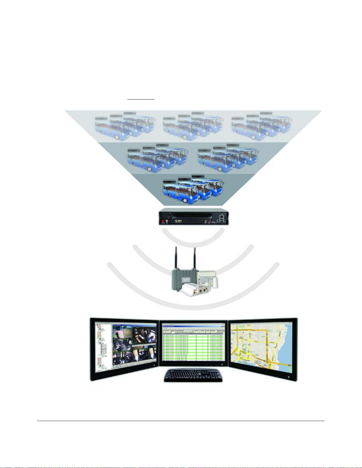
The DX-HD DVR integrates with the optional Smart-Reach Mobile wireless technology and works
with optional vMax Commander and vMax View video management software for on-board video data
management, as shown in Figure 1-1
.
Figure 1-1
1–2 700-0190 R002
DX-HD DVR System with Smart-Reach Mobile Wireless and vMax Commander Software
Page 9
1.2. DX-HD DVR Product Features
The Explorer DX-HD has the following product features:
• supports up to 12 video channels and 12 audio channels
• has one high-definition video channel
• records up to 30 frames per second (FPS) at 720 × 480 D1 resolution on all video channels
simultaneously
• offers H.264 and MJPEG video compression for enhanced compression and quality
• has removable dual HDD cartridge
• stores up to 2.0 TeraBytes (TB)
• offers dual stream recording; high-resolution stream for playback on a PC, and a lower resolution
stream for viewing over a cellular phone network
• DVR Health Check monitors DVR and hard drive status and notifies the administrator of any
issues, ensuring all onboard events are captured, using the vMax Commander video management
software Health Check feature
• uses Global Positioning System (GPS) technology for Geo-fencing, to designate a geographic
boundary for the vehicle and provides an alert if the vehicle leaves the area
• logs and displays G force data and provides incident alerts with G-Sensor
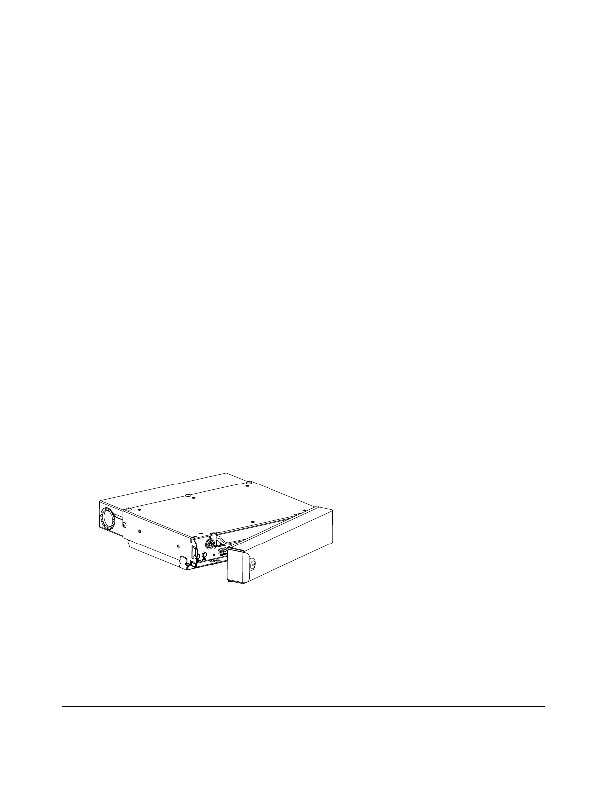
• authorized personnel only restricted access to DVR via keyed Security front cover and secure
cable cover with slotted cable entries, see Figure 1-2
• configure, playback, and archive video from the DVR locally with trackball mouse, monitor, and
DVR On Screen Display (OSD)
• configure, playback, and archive video from the DVR remotely with vMax Web via Ethernet
• interfaces with network using RJ-45 connections on the front and back panels, see Figure 1-3 and
Figure 1-4.
• mounting options that can accommodate horizontal or vertical installation
Introduction
Figure 1-2
700-0190 R002 1–3
DX-HD DVR with Security Front Cover and Secure Cable Cover
Page 10
Introduction
1.2.1. DX-HD System Components
A typical DX-HD Plus system has the following components (see DVR Video Co nfiguration Playback
and Archiving, on page 1–9):
• Explorer DX-HD DVR and DVR drive with dual HDD cartridge
• Cameras and camera cables, one connector per camera
• HD camera option
• Smart-Link™ module and cables and harnesses
• Diagnostic Button
• Optional equipment: Smart-Reach™ Mobile wireless bridge, portable video monitor, speed
harness, GPS, and IR illuminator
• Trackball mouse for navigating on-screen display
1.2.2. Recording Capacity for DVR Hard Drive Storage
The DX-HD DVR uses H.264 video compression to extend the recording time on the dual HDD
cartridge. The recording time varies, depending on the FPS, resolution (horizontal x vertical pixel
count), and picture quality settings. Lower picture quality results in higher compression and a lower
memory requirement. Higher picture quality results in lower compression and a higher memory
requirement.
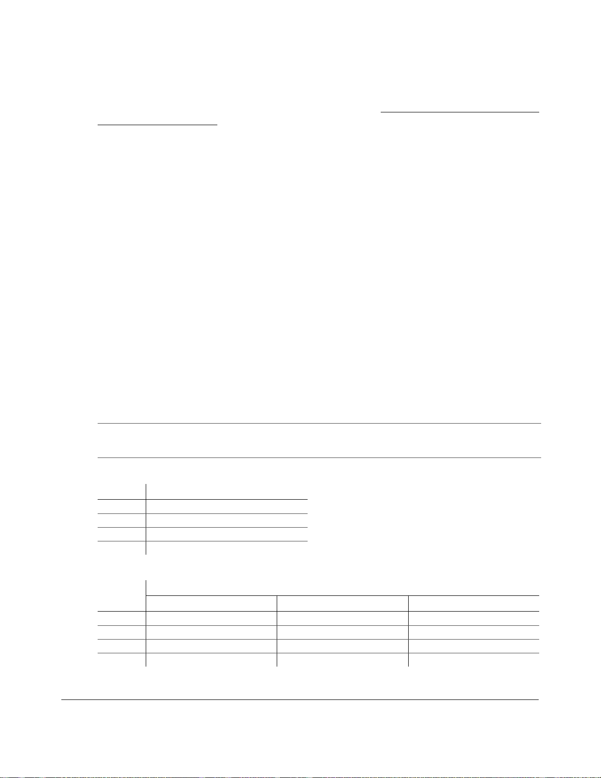
The following tables estimated recording time of analog and HD cameras in hours for 1 TB (two 500
GB dual HDD cartridges), including Record 2 set at 5 FPS, (3) 360x240. 1.5 TB and 2 TB cartridges
are also available.
Important:
recorded. External facing cameras will consume disk space more rapidly. Estimated recording times are based on simulated
test conditions. Actual recording times will vary greatly.
Table 1-1
FPS Picture Quality (3) 720p (1280x720)
30 864 hours
15 1728 hours
10 2608 hours
5 5184 hours
Table 1-2
FPS
30 168 hours 109 hours 68 hours
15 285 hours 193 hours 125 hours
10 431 hours 314 hours 171 hours
5 610 hours 483 hours 294 hours
The average image size is dependent on the scene content, lighting conditions, and amount of movement
Estimated Recording Time for 1 HD Camera
Estimated Recording Time for 1 HD and 12 Analog Cameras
Picture Quality (3) 720p (1280x720)
CIF 360×240 resolution Half D1 720×240 resolution D1 720×480 resolution
1–4 700-0190 R002
Page 11
Introduction
1 2 3
45678910
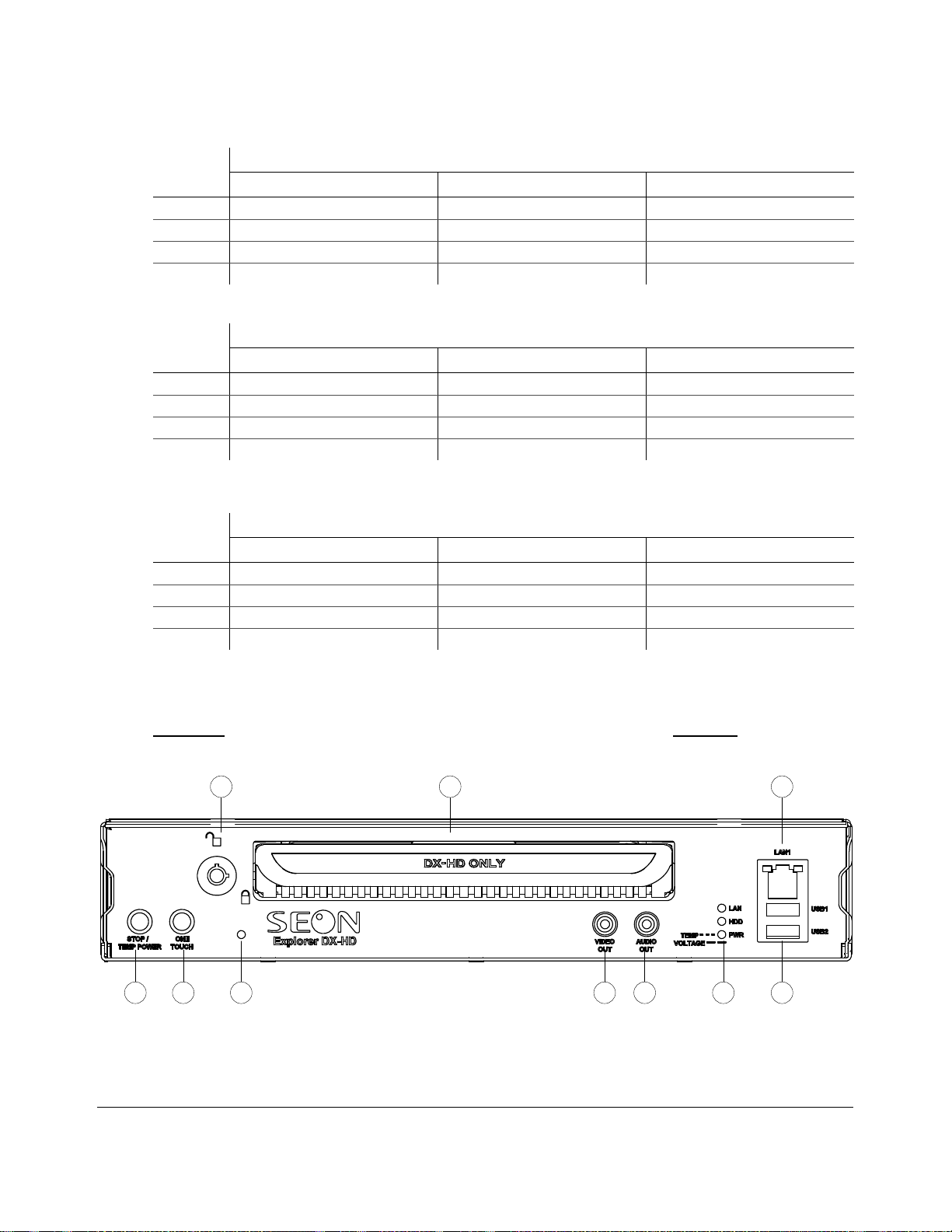
Table 1-3
FPS
30 214 hours 146 hours 104 hours
15 354 hours 216 hours 179 hours
10 577 hours 394 hours 232 hours
5 699 hours 514 hours 353 hours
Table 1-4
FPS
30 576 hours 288 hours 144 hours
15 1152 hours 576 hours 288 hours
10 1728 hours 864 hours 432 hours
5 3456 hours 1296 hours 864 hours
Table 1-5
FPS
30 864 hours 432 hours 216 hours
15 1728 hours 864 hours 432 hours
10 2608 hours 1304 hours 652 hours
5 5184 hours 2592 hours 1296 hours
Estimated Recording Time for 1 HD and 8 Analog Cameras
Picture Quality (3) 720p (1280x720)
CIF 360×240 resolution Half D1 720×240 resolution D1 720×480 resolution
Estimated Recording Time for 12 Analog Cameras
Picture Quality (3)
CIF 360×240 resolution Half D1 720×240 resolution D1 720×480 resolution
Estimated Recording Time for 8 Analog Cameras
Picture Quality (3)
360×240 resolution 720×240 resolution 720×480 resolution
1.2.3. Front Panel Features
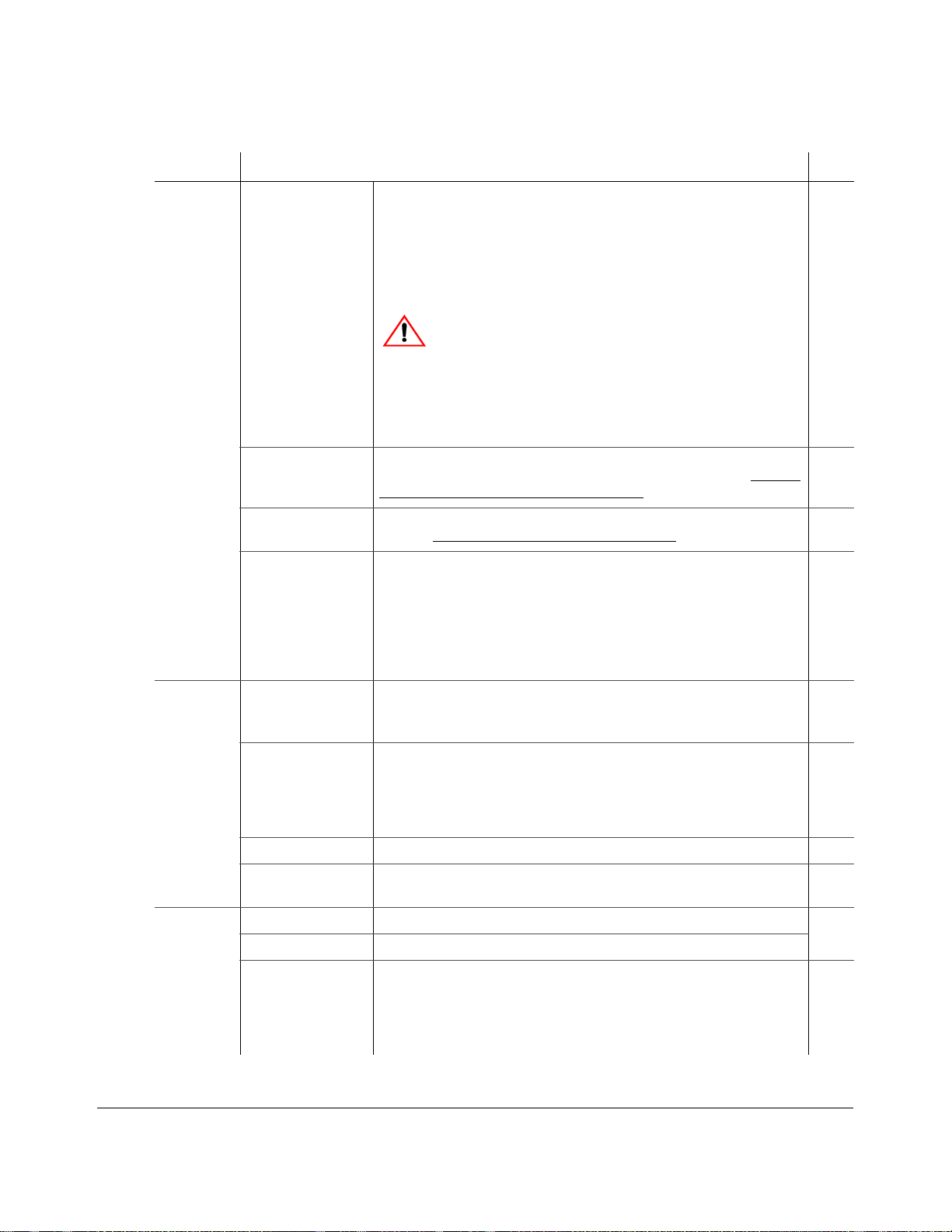
Figure 1-3 shows the front panel features followed by a short description in Table 1-6.
Figure 1-3
DX-HD DVR Front Panel
700-0190 R002 1–5
Page 12
Introduction
Table 1-6
Feature Description Item
Controls DVR drive lock Requires the dual HDD cartridge key to unlock and remove the dual HDD
DX-HD DVR Front Panel Feature Descriptions
1
cartridge.
When the DVR is recording, turn the hard drive key to the open position.
The DVR HDD Activity LED blinks while the recordings are stopping.
After ten seconds or until the red HDD activity indicator is off, gently pull
out the hard drive.
CAUTION: Data Loss
Do not remove the dual HDD cartridge until 10 seconds after power to the
hard drive is turned off and the red HDD activity indicator is off. Failure to
do so may result in lost data.
Dual HDD cartridge Remove the dual HDD cartridge to a separate location for playback using
the DVR HDD to USB Interface connected to a PC or laptop. See Remove
and Replace the DVR Hard Drive, on page 2–2.
ONE TOUCH Press to start one touch downloading to a USB memory device in a USB
port. See Using One-Touch Download, on page 2–14
STOP/TEMP PWR • Powers on the DVR for five minutes, when held for more than 5
seconds.
• Powers down the DVR if held for more than 5 seconds when the DVR
is in temporary power mode, or in shutdown sequence and ignition is
off.
• Press the STOP button to temporarily stop the DVR from recording or
playing.
Connections LAN1 Ethernet port with RJ-45 connector for connecting to the local area network
LAN). Ethernet is used to connect either to a PC, laptop, or directly to the
(
Smart-Reach wireless bridge and other equipment.
.
2
9
10
3
USB1, USB2 ports
(supporting USB 2.0
AUDIO OUT (red) Audio output RCA jack. 6
VIDEO OUT
(yellow)
Indicators LAN (green) Illuminates when there is network activity on the LAN connection. 5
HDD (red) Illuminates when the DVR is accessing the dual HDD cartridge.
PWR (green LED)
TEMP
VOLTAGE
1–6 700-0190 R002
Supports USB devices for:
• Copying video and audio information.
)
• Exporting video clips.
• Updating the DVR firmware.
• Connecting the trackball mouse.
Video outp ut RCA jack for configuring the DVR and viewing recorded
video.
• Illuminates when the DVR is powered on.
• Flashes quickly when the DVR cannot power up due to temperature
limitations.
• Flashes slowly when the DVR cannot power up due to voltage
limitations.
4
7
Page 13
1.2.4. Back Panel Features
1 2 3 4 5
6
7
89
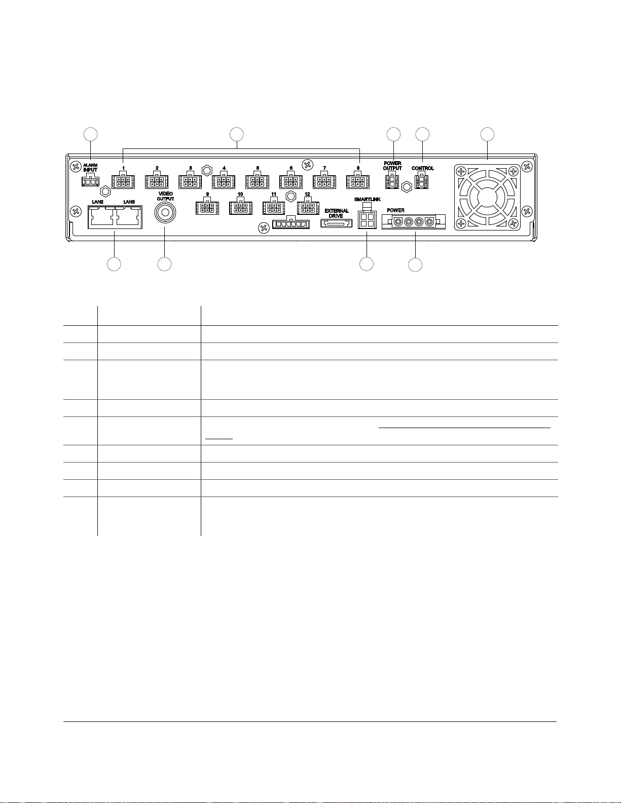
Figure 1-4 shows the back panel features followed by a short a description.
Introduction
Figure 1-4
Back Panel Features
Item Feature Description
1 ALARM INPUT Alarm input connector for the alarm button and cable (2-pin).
2 1 to 12 Twelve camera input connectors (6-pin).
3 POWER OUTPUT Auxiliary power connector (2-pin). Used to supply DVR p ower to the HD Camera using the HD
Camera connector cable 060-0670. Turns off after recording as configured in delay settings. See
the DX-HD DVR Installation Guide 700-0189 for details.
4 CONTROL Control connector (2-pin) for controlling the Smart-Reach Mobile wireless bridge equipment.
5 Fan Intake fan with filter and removable cover. See Chapter 5, Maintenance, Troubleshooting, and
Service.
6 POWER Power input connector (4-pin) for connecting the power harness.
7 SMART-LINK Smart-Link connector.
8 VIDEO OUTPUT Configurable video output for viewing video, BNC connector
9 LAN2, LAN3 Ethernet ports with RJ-45 connector for connecting an HD camera or to LAN. Ethernet is used
to connect either to a PC or laptop or directly to the Smart-Reach wireless bridge and other
equipment.
700-0190 R002 1–7
Page 14
Introduction
1
2
3
4
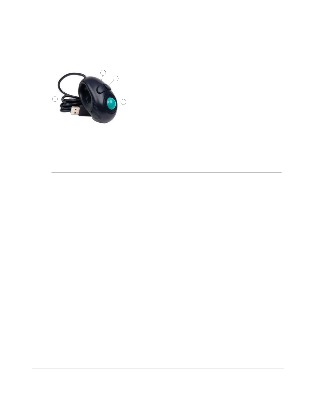
1.2.5. Using the Trackball Mouse
Figure 1-5 shows the buttons on the trackball mouse followed by a description of the features.
Figure 1-5
Trackball Mouse
To do this… Use
Select the highlighted menu option by pressing the middle button. 1
Select the highlighted menu option by pressing the left button with your thumb. 2
• Delete a character entered into a field or go back to a previous items by pressing the button on the right.
3
• Press the right button to enter the configuration menu.
Move the cursor around the screen by rotating the blue button. 4
Many other USB mice will also work with the DVR.
1–8 700-0190 R002
Page 15

1.3. DVR Video Configuration Playback and Archiving
Here is an introductory overview of the configuration, playback, and archiving methods available on
the DX-HD.
The DX-HD DVR content can be accessed and archived in three ways:
• locally via OSD, mouse, and portable video monitor. See DVR Operation, on page 2–1
• remotely via vMax Web browser interface and Ethernet/wireless connection.
See vMax Web Remote Operation, on page 3–1
• via vMax V i ew video managemen t software and dual HDD cartridge interface.
See vMax View and DVR Hard Drive Interface, on page 2–3
Explorer DX-HD Installation Guide, 700-0199
vMax Commander Software User Guide , 700-0120
vMax View User Guide, 700-0137
The following table shows which methods support video configuration, playback, and archiving.
To do this… Use...
.
. See also:
Introduction
.
On-screen display
with monitor and
trackball mouse
Configure the DVR menu settings.
Playback and view recorded video with single channel view
or multiple views.
Playback recorded HD camera video in single channel view
or with multiple views.
Search for video from a Segment, an Events list, or by time
and date.
Archive video to .avr file format.
Archiving options — each individual channel can be
archived as an
or .jpg files
AVI file and individual images saved to .bmp
x
vMax Web remote
access with
Internet Explorer
DVR Hard Drive
Interface & vMax
View software
700-0190 R002 1–9
Page 16

Introduction
1–10 700-0190 R002
Page 17

DVR Operation
This chapter provides information on using the DX-HD DVR, and viewing recorded video. This
chapter contains the following sections:
Remove and Replace the DVR Hard Drive, on page 2–2
Search, Playback, and Archive Video, on page 2–2
vMax View and DVR Hard Drive Interface, on page 2–3
On-Screen Display Access, on page 2–4
Playback Menu Access, on page 2–6
Using the Search Function, on page 2–8
Using the Archive Function, on page 2–11
Copy to USB, on page 2–13
Using One-Touch Download, on page 2–14
DVR Operation
CHAPTER 2
700-0190 R002 2–1
Page 18
DVR Operation
2.1. Remove and Replace the DVR Hard Drive
The DVR has two hard drives contained in a single removable cartridge. A dual HDD cartridge lock
secures the hard drive during operation. Use the hard drive key to lock and unlock the dual HDD
cartridge.
CAUTION: Data Loss Risk
Do not remove the dual HDD cartridge until the red HDD activity indicator is off. Failure to do so may
result in lost data. While the dual HDD cartridge is hot swappable (the dual HDD cartridge can be
removed when the DVR is powered up), do not remove the dual HDD cartridge while the DVR is
recording, as the video segment may not be recorded.
To remove the dual HDD cartridge:
1. Insert the dual HDD cartridge key.
2. Turn the key counter clockwise by ¼ turn until the hard drive lock is in the unlocked position.
3. After the red HDD LED is off, gently pull out the dual HDD cartridge.
CAUTION: Hard Drive Identification
Notice that the DX-HD hard drive has an identifying label to identify it as for this DVR series. Pla cing the DX-HD
hard drive in a DX12 DVR and vice versa will result in lost data.
To replace the dual HDD cartridge:
1. Slide in a dual HDD cartridge until the hard drive seats inside the front panel.
2. Insert the dual HDD cartridge key, turn clockwise by ¼ turn until the hard drive lock is in the
locked position.
2.2. Search, Playback, and Archive Video
The HD camera output is visible from vMax Web and vMax Vi ew, but not in the DVR onscreen
monitor view.
To search, playback, and archive recorded video, use one of three methods:
vMax View and dual HDD cartridge Interface
Remove the dual HDD cartridge from the DVR, and use the DVR HDD to USB Interface and vMax
View software. See vMax View and DVR Hard Drive Interface, on page 2–3
On Screen Display Menus
For local video access, connect a portable video monitor to the DX12 DVR. Use the trackball mouse to
navigate the OSD menus. See Using the Search Function, on page 2–8
vMax Web Menus
For remote video access, use a laptop and the vMax Web browser user interface with Ethernet
connectivity. Video recorded with the HD camera is only available for playback via vMax Web if the
DVR’s Ethernet port is connected to a network. See vMax Web Remote Operation, on page 3–1
.
.
.
2–2 700-0190 R002
Page 19
2.3. vMax View and DVR Hard Drive Interface
D
X
-
HD
O
N
L
Y
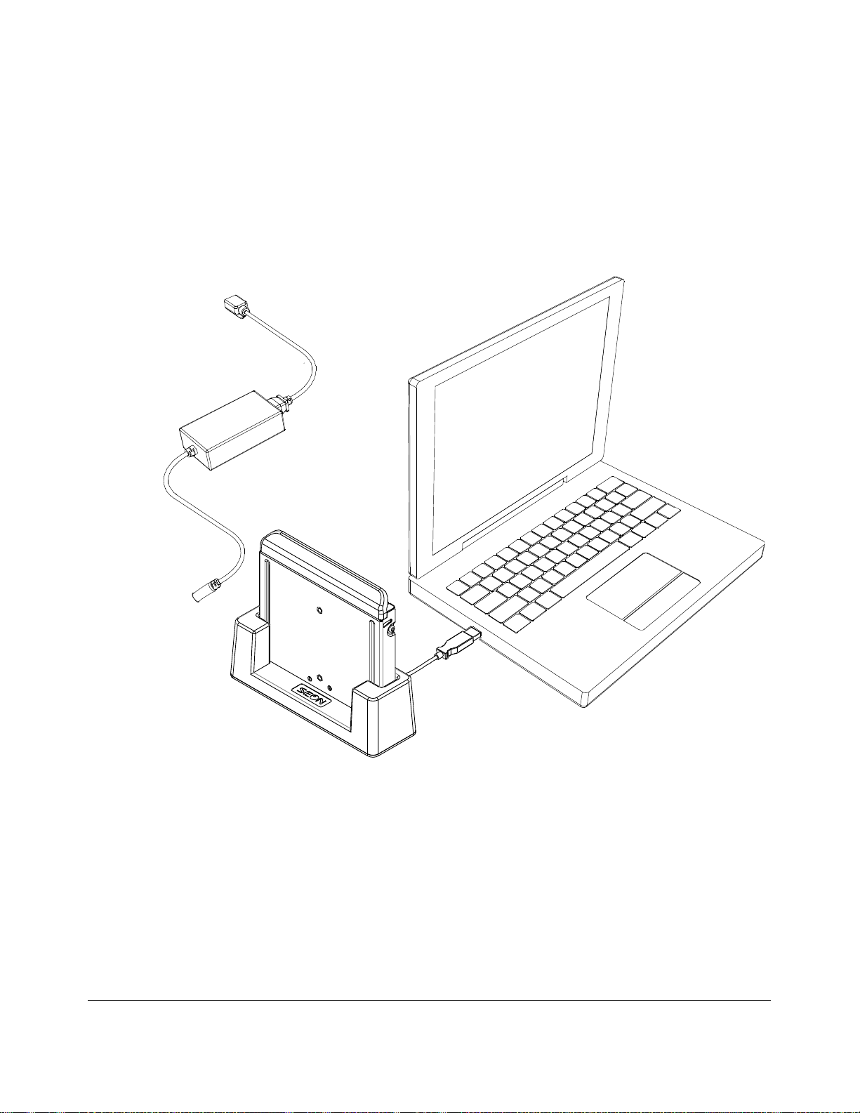
The DX-HD hard drive interface is provided with vMax V iew software to accommodate the DX-HD
dual HDD cartridge. It requires AC power to read the dual HDD cartridge.
To access vide o from the hard drive using vMax View:
1. Remove the dual HDD cartridge from the DVR.
2. Connect to a USB port on a PC or laptop with vMax View installed, as shown in Figure 2-1.
DVR Operation
Figure 2-1
DX12 Hard Drive Interface with Hard Drive
3. Open the vMax View software to search, pla yback and archive dual HDD cartridge contents.
vMax View sees the information read from the dual HDD cartridge as a single drive full of data.
See vMax View User Guide 700-0137 for detailed procedures.
700-0190 R002 2–3
Page 20
DVR Operation
Portable
Video Monitor
DX-HD DVR
USB Mouse
2.4. On-Screen Display Access
Use the On-Screen Display mode to locally access the dual HDD cartridge content.
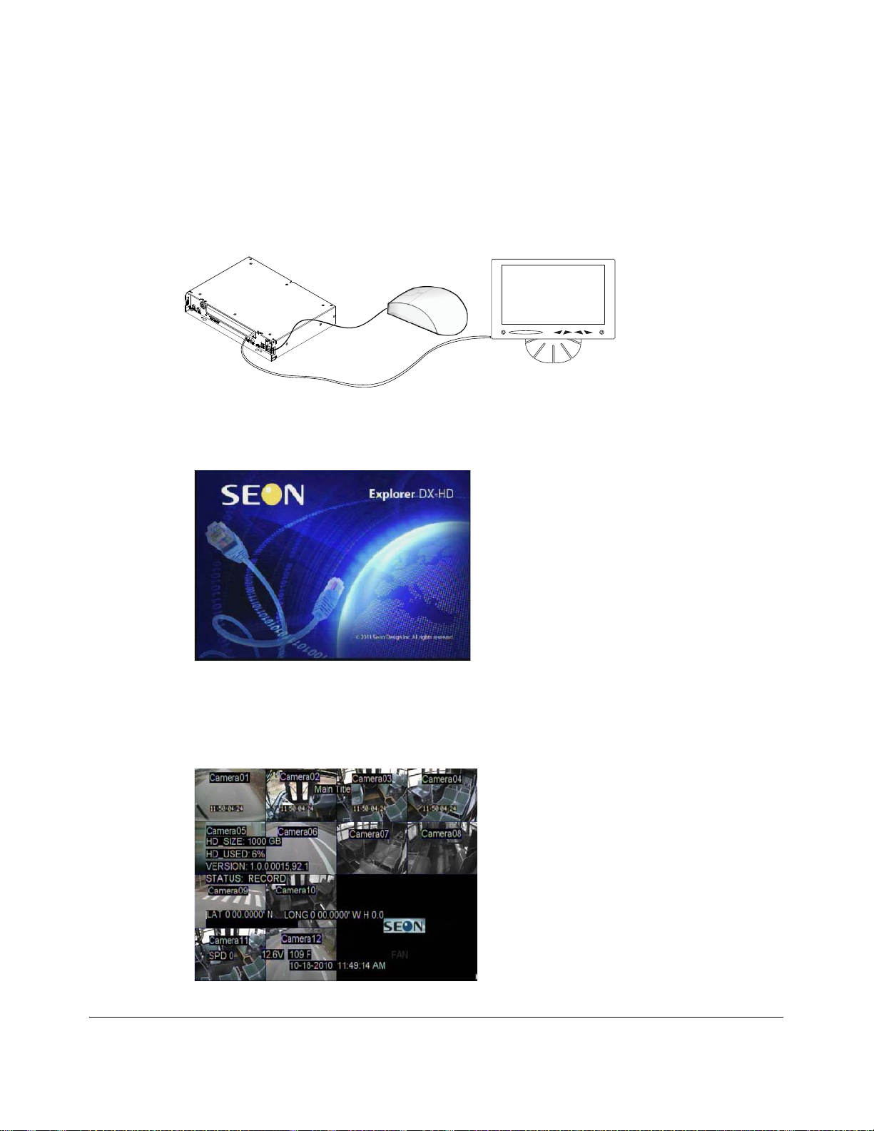
To use the on-screen display (OSD) with trackball mouse and monitor:
1. Connect a portable video monitor to the VIDEO OUT RCA jack on the DX-HD front panel.
Plug the USB trackball or mouse in the USB socket on the front of the DVR.
Figure 2-2
Mouse and Monitor Connected to DVR
When the on-screen display starts up, the Seon Explorer DX-HD splash screen (see Figure 2-3)
appears briefly before the DVR enters live view.
Figure 2-3
DX-HD Splash Screen
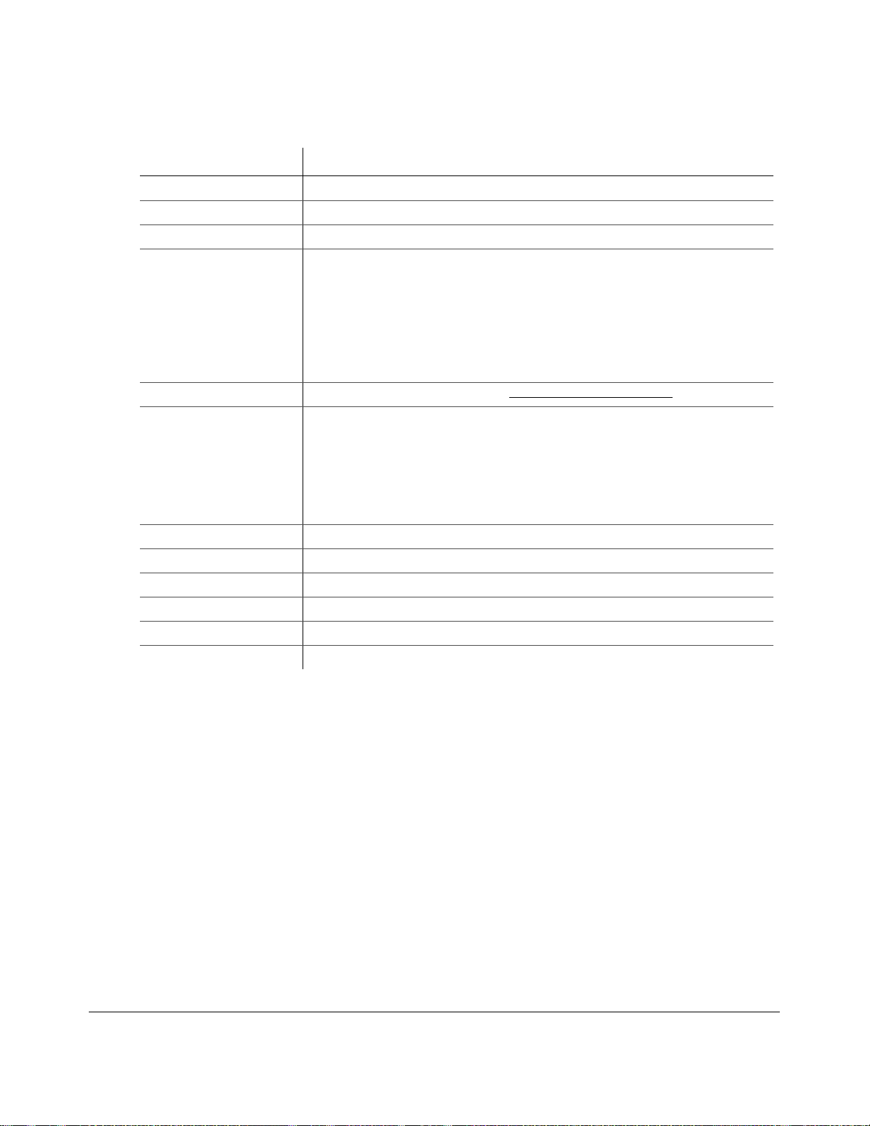
During recording and live viewing, the screen information is dynamic and can include the items
shown in Figure 2-4 and described in Table 2-1. The screen items can be configured in the main
menu.
Figure 2-4
2–4 700-0190 R002
On-Screen Display during Live Viewing and Recording
Page 21
DVR Operation
Table 2-1
On-Screen Display Information
Feature Description
Camera 1 to Camera 12 Camera titles, maximum 8 characters each.
Main_Title Main title of the DVR, maximum 32 characters.
HD_Size Formatted size of the dual HDD cartridge, in gigabytes (GB).
HD_Used Percentage of recorded video on the dual HDD cartridge. At 100%, the message displayed
depends on the Repeat Record settings in the Recording Settings menu.
• When Repeat Record is set to On, the HD Used message reads “N/A Repeating”. N/A
means that information on how much of the hard drive space is used is not available
because the hard drive is full. Repeating means the DVR continues recording,
overwriting the oldest recorded data.
• When Repeat Record is set to Off, the HD Used message reads “100%”. The DVR
stops recording.
Version DVR firmware version. To update, see Firmware Updates, on page 4–2
Status DVR operation status:
• LIVE (live mode not recording)
• PLAYBACK (the DVR is playing locally , displays RECORD, ALARM or TIMER)
• RECORD (normal recording)
• ALARM (alarm recording)
• TIMER (timer recording)
• V. LOSS (video loss or camera signal loss)
Speed Display Vehicle speed.
Voltage System voltage from 8 to 32 VDC.
.
Temperature DVR temperature in degrees Fahrenheit or Celsius.
GPS If the GPS receiver is installed, the vehicle’s latitude and longitude is displayed.
Time and Date Current/recorded time and date.
AC (Alarm count) Count of alarm(s) triggered. Resets to 0 when the DVR is restarted.
2. Use the trackball mouse (right-click) to access the DVR’s configuration, playback, and archiving
menu settings as required.
3. Proceed to the Configuration or Operation and Playback chapters for details on available setting
options.
700-0190 R002 2–5
Page 22
DVR Operation
2.5. Playback Menu Access
Use the Playback menu to search, playback, and archive video directly from the DVR
hard drive.
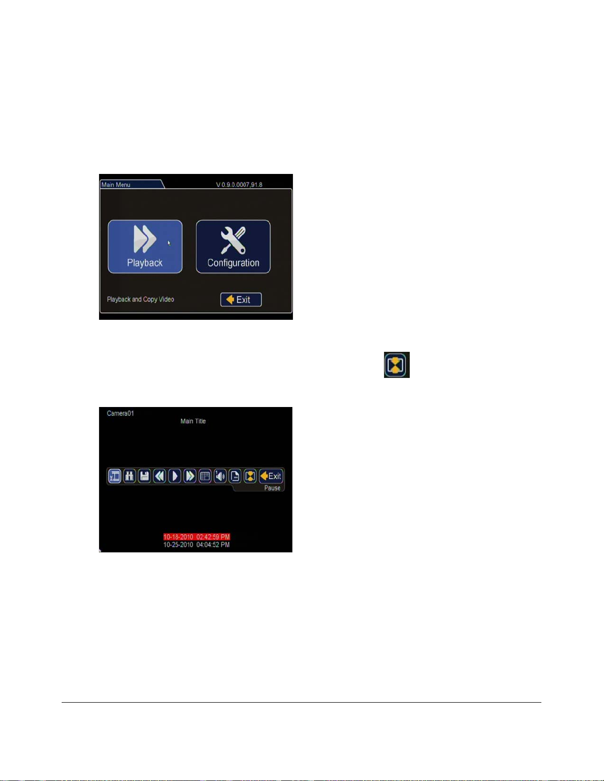
To access the playback menu from the OSD:
1. In the OSD view, right-click the live view to ac cess the Main Menu and click Playback.
Figure 2-5
Main Menu > Playback
2. In the middle of the screen click the Show/Hide Toolbar icon .
The Playback T oolbar appears.
Figure 2-6
Playback Toolbar Screen
2–6 700-0190 R002
Page 23
DVR Operation
1
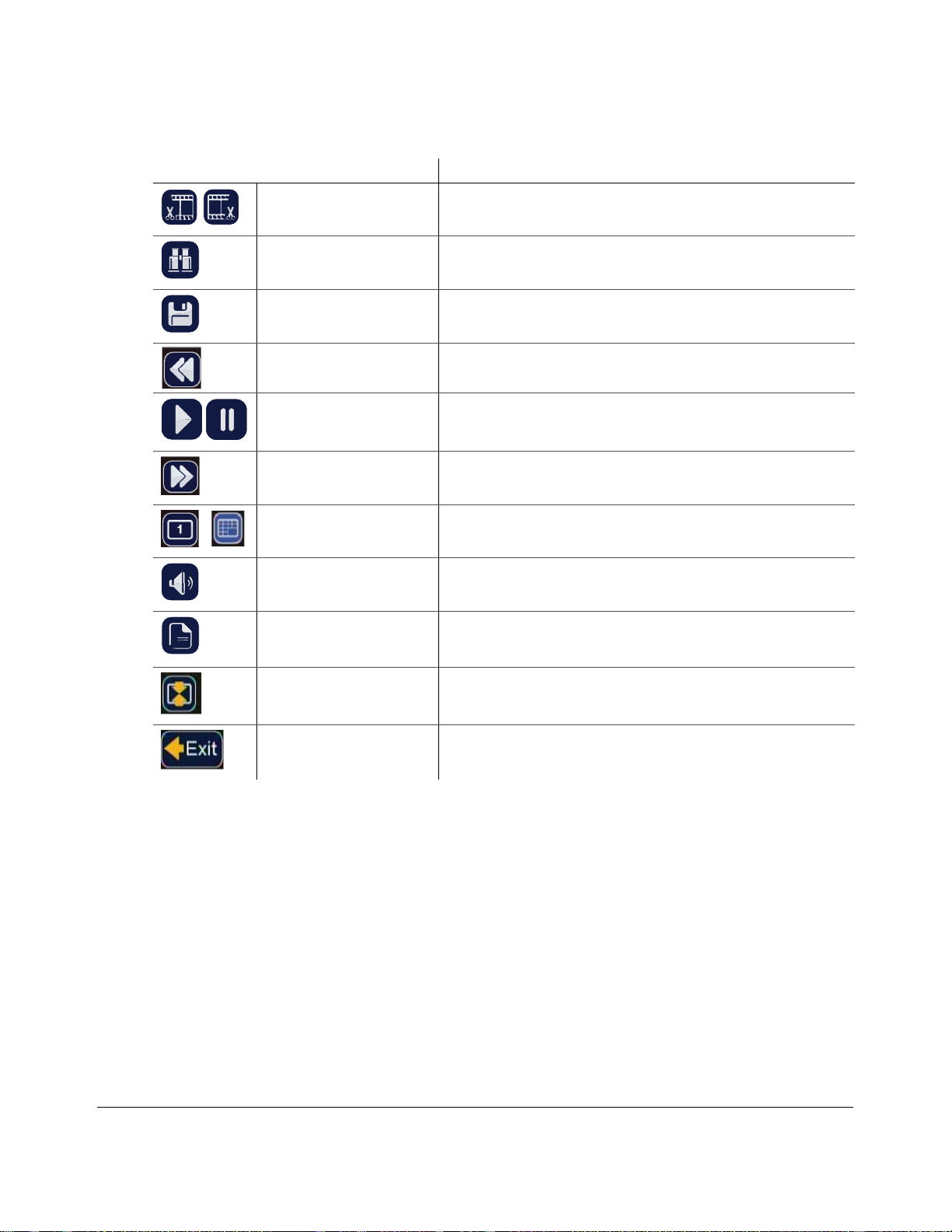
Table 2-2
Toolbar Icon Description
Playback Toolbar Items
Start of clip/End of clip Click to set the start of clip and end of clip points for one-touch
download.
Search Click to search by date, time or by Time, Alarm, Signals, or System
Event. See Figure 2-7 and Figure 2-8.
Archive Click to display Archive screen to copy a video clip to a USB memory
device.
Rewind • Click to reverse during playback 1, 2, 4, 8, 16, or 32×.
• With playback paused, each click reverses the video by one frame.
Play/Pause Click to start playback.
Click again to pause playback.
Fast Forward • Click to fast forward during playback 1, 2, 4, 8, 16, or 32×.
• With playback paused, each click advances the video by one frame.
Individual camera/16-up
mode
Audio Click to cycle through Audio channels 1 to 12.
Click to display Camera 1 to 12 or 16-up mode.
Metadata Text overlay Click to show or hide the text overlay such as temperature, system
voltage, GPS data (if recorded), speed, date, and time. These items can
be set in the Title/Display menu or Diagnostic Display sub-menu.
Show/Hide Playback toolbar Click to show or hide the playback toolbar.
Exit Click to exit to on-screen display.
700-0190 R002 2–7
Page 24
DVR Operation
2.5.1. Using the Search Function
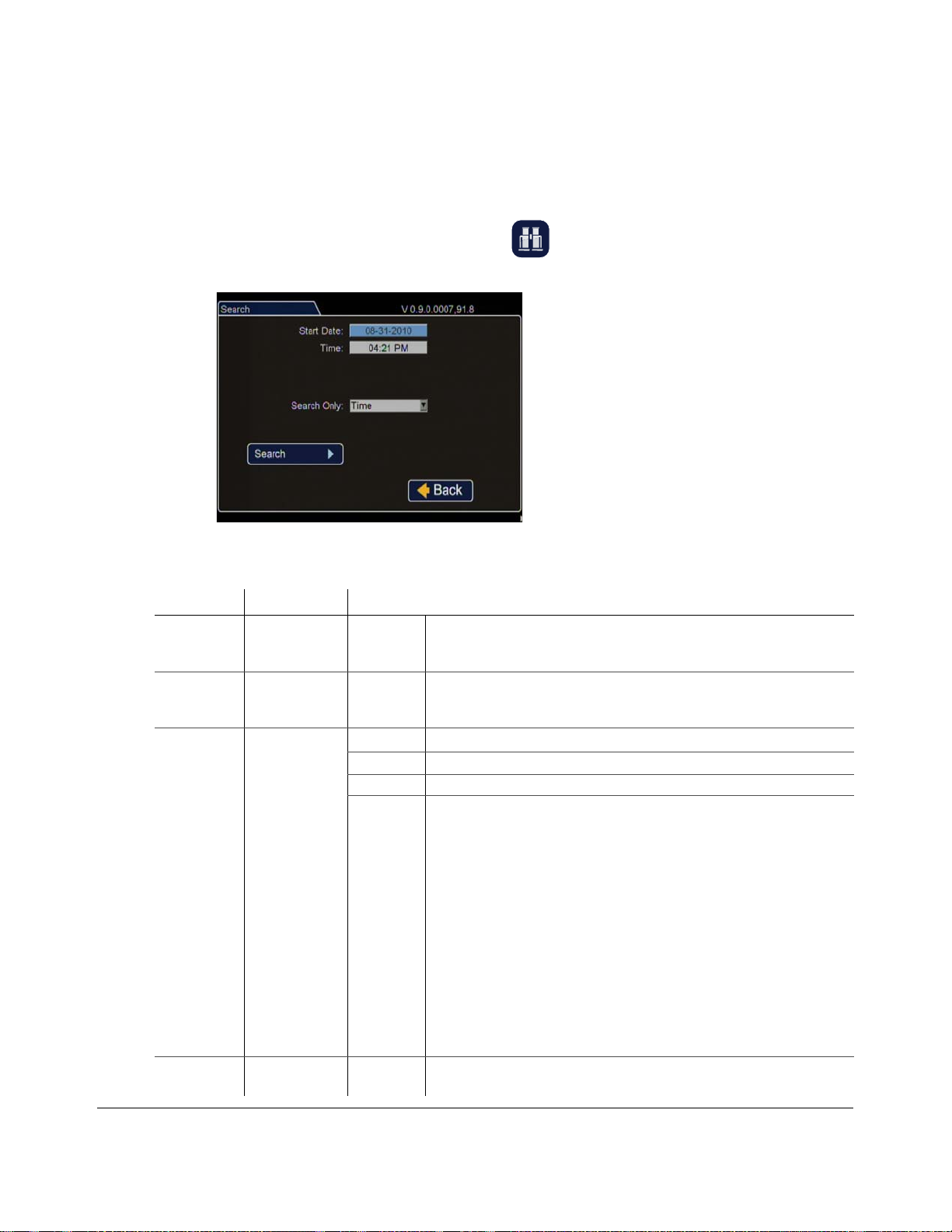
The DX-HD includes a powerful search function that lets you quickly find recorded information by
Date and Time, Alarm, Signals, and by System Event.
To view the search menu:
1. From the playback tool bar, click on the Search
The items appearing in the dialog box will depend on the item selected in Search Only box.
icon. to display the Search menu.
Figure 2-7
Search Menu
Table 2-3
Search Configuration Items
Menu Item Description Value [Default]
Start Date Set the start
date for the
search.
Time Set the start
time for the
search.
Search Only Select the
desired search
type.
Search Press Enter to
Start Search.
• [Time]
• Alarm • Alm0, Alm1, Alm2, Alm3, Alm4, All
• Signals • Signal1, Signal2, Signal3, Signal4, Signal5, All
• System
Event
•An Alarm event, n = alarm input
•Dn Hard Drive over temperature warning, n = disk number
• GPS = geo fence event
• LH Logical head: beginning of recording date and time after hard drive
•LUn Logical user login n = 1 is Administrator, 2 is Operator , 3 is
• PH Physical head: Beginning point of hard disk space
•PL Power loss
•RUn Remote user login through HTTP, n = user level
• Sn Signal, n = signal input
•Tn Scheduled reco rding
•TN
•Vn Video loss, n = camera
•All
has been overwritten
General
2–8 700-0190 R002
Page 25
DVR Operation
Table 2-4
Event Description Event Description
Almn Off Alarm Off GSN Z+ Limit exc ee d ed in Z+
Almn On Alarm On Idle0 Idle limit not exceeded
EXSpeed Excessive speed occurred Idle1 Idle limit exceeded/stopped
FAN Fan fault IG0 Ignition off
GPS Crossed GPS Fence IG1 Ignition on
GSN Gse nsor exceeded limit LIVE DVR changes to live mode
GSN X- Limit exceeded in X- PLoss Power Loss
GSN X+ Limit exceeded in X+ Rec On Normal Recording event
GSN Y- Limit exceeded in Y- RUn Remote User Login n
GSN Y+ Limit exceeded in Y+ Signaln Signal Event n
GSN Z- Limit exceeded in Z- Vlossn V ideo loss on channel n
DVR Event Descriptions
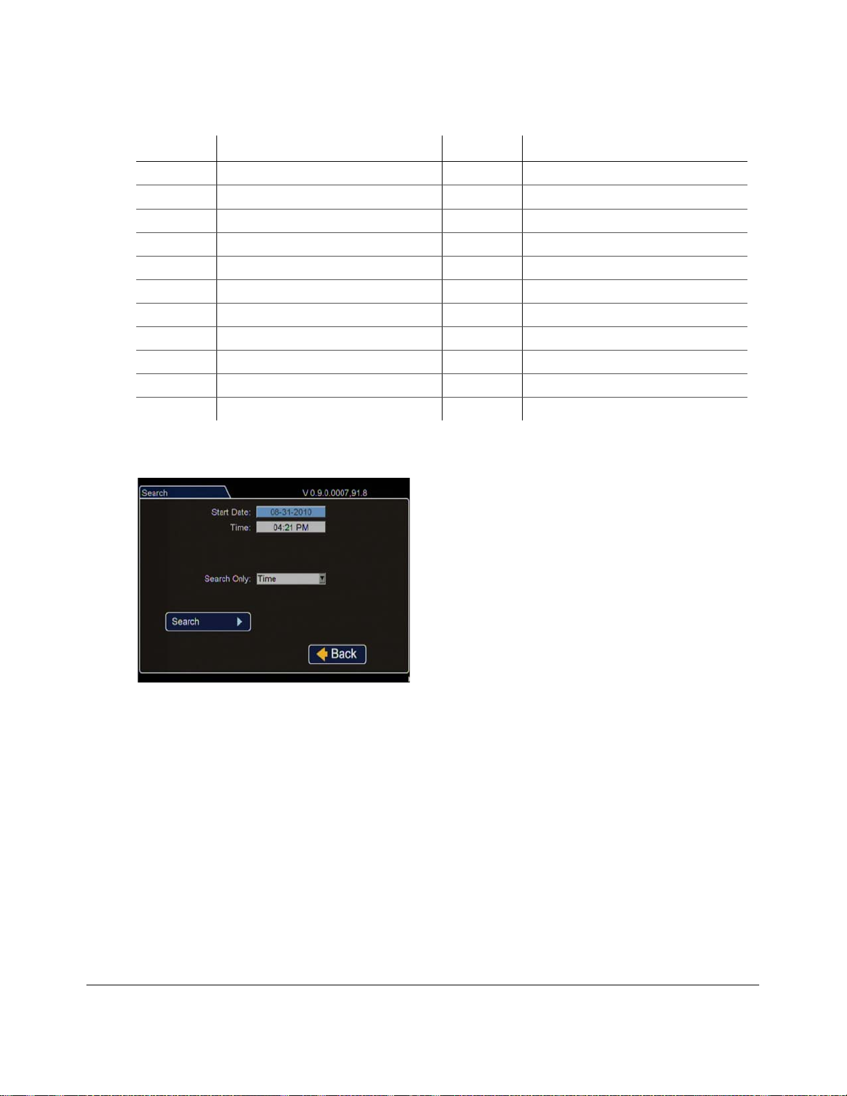
2. Click the Start Date and Time fields to set the search ranges. Click Search.
Figure 2-8
Search Menu
Depending on the item selected in the Search Only box, the DX-HD will retrieve recorded video.
For example, select Time or Alarms, Signals or System Event to display the recorded video at the
time point selected.
700-0190 R002 2–9
Page 26
DVR Operation
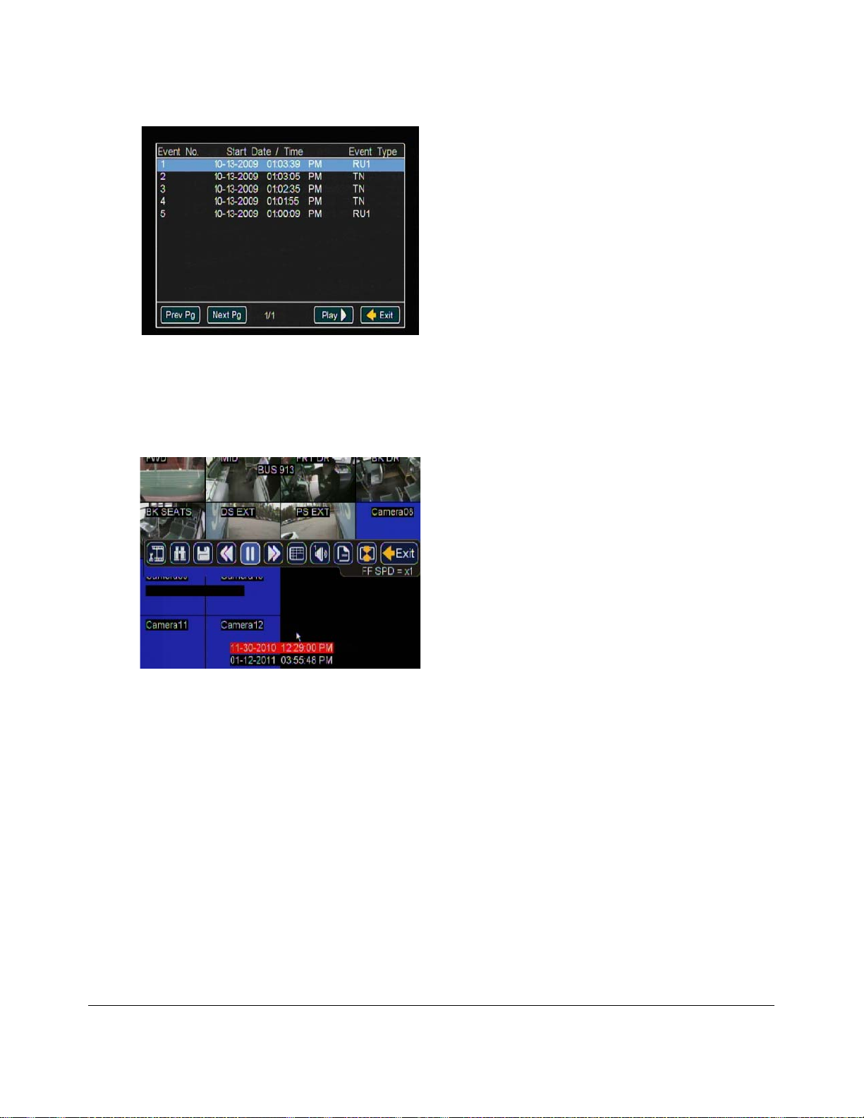
Figure 2-9
Event List
3. From the Event List, select the required list item.
4. Click Play to review the video. Note the time when the event occurs and which camera captures
the event details.
Figure 2-10
Playback View
2–10 700-0190 R002
Page 27
2.5.2. Using the Archive Function
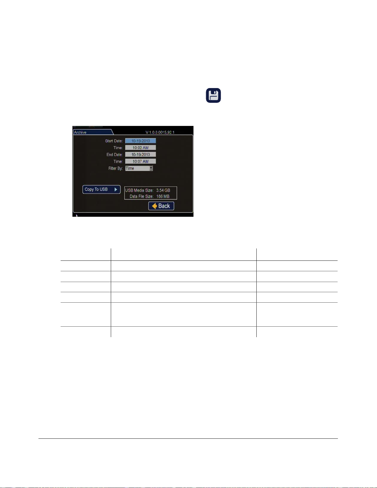
An archive dialog box lets you specify the start and end date and time of the video clip to be archived
to a USB memory device.
To view the Archive menu:
1. From the Playback tool bar, click on the Archive icon.
The Archive menu displays as shown in Figure 2-1 1. The items appearing in the dialog box depend
on the item selected in the Filter By drop down menu.
DVR Operation
Figure 2-11
Table 2-5
Menu Item Description Value [Default]
Start Date Set the start date (month, day, and year) for the archive clip. [Current]
Time Set the start time for the archive clip. [1hour before current time]
End Date Set the end date (month, day, and year) for the archive clip. [Current]
Time Set the end time for the archive clip. [Current time]
Filter By: Filter recorded data by one of three types. • Time
Copy to USB Click to archive the video clip to USB memory device.
Archive Menu
Archive Menu Items
•Alarm Data
• Log File
700-0190 R002 2–11
Page 28
DVR Operation
To establish an archive clip:
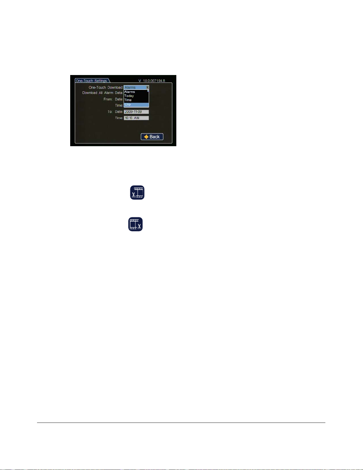
To archive a clip using the one touch download, you must have the One touch settings (in the system
settings menu) set to "Clip". See Figure 2-9.
Figure 2-12
One-Touch Settings: clip
1. Use the video playback or search controls to view the start date and time of the video you want to
archive.
2. Click start of clip icon to set the start point of the archive clip.
3. Locate the end of the video you want to archive in Play mode, and click Pause.
4. Click end of clip icon to set the end point of the archive clip.
5. Press the ONE TOUCH button on the DVR front panel.
The One-Touch Process menu appears. The archive clip is saved to the USB memory device.
6. Remove the USB drive when complete and return to the Archive screen.
2–12 700-0190 R002
Page 29
2.5.3. Copy to USB
To copy video files to a USB memory device:
1. Insert a USB memory device into the USB port on the DVR front panel.
2. In the Playback tool bar, click the archive icon to display the Archive screen.
DVR Operation
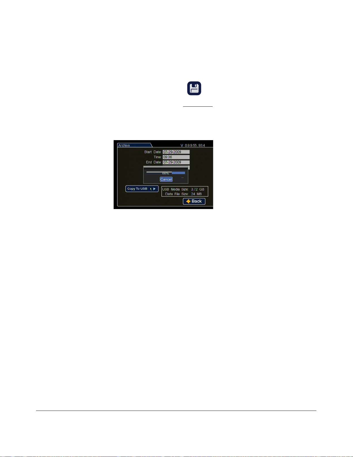
3. Click on Copy to USB to start archiving. See Figure 2-13
A progress bar appears.
4. OR Click Cancel to stop the archiving process.
5. Remove the USB drive when complete and return to the Archive screen.
Figure 2-13
2.5.3.1. Archive Segmentation
Archives larger than 2GB are segmented when dowloaded from the DX, MX, TX, and TL series
DVRs. The segments are saved as separate archive files with the following naming conv ention:
• Archive.avr (original)
• Archive-002.avr (next segment)
• Archive-003.avr (next segment)
If your archive seems too short it could have been segmented.
.
Copy to USB Progress Bar
vMax View will automatically stitch together segmented archive video when played.
700-0190 R002 2–13
Page 30
DVR Operation
Portable
Video Monitor
DX-HD DVR
USB Mouse
USB Input
ONE
TOUCH
Button
STOP/TEMP PWR
Button
2.6. Using One-Touch Download
Use One-Touch download for downloading specific alarm or event information to a USB memory
device via the USB port. One-Touch download is available when the DVR is in live, playback, or
record mode. Use the ONE TOUCH button on the DVR.
Video is downloaded in the Seon proprietary format and can be viewed using the vMax View
application. See the vMax View User Guide, 700-0137.
Recommendation: Retrieving several minutes or hours of video may take a long time. For large volume video transfers,
retrieve the dual HDD cartridge from the DVR and view the video playback via the vMax software.
The default setting for One-Touch download is Alarms. See the One Touch Settings menu in the
DX-HD DVR Installation and Configuration Guide, 700-0189, for details on setting the menu to Clip
to enable One-Touch downloads.
To use the One-Touch download option:
1. If the DVR is powered off, press the STOP/TEMP PWR button for 5 seconds to power up the
DVR.
2. When the DVR is on, connect a portable video monitor to VIDEO OUT on the DVR front panel.
3. Insert a USB memory device into the USB port on the DVR front panel.
4. Press the ONE TOUCH button to download information to the USB memory device.
2–14 700-0190 R002
Figure 2-14
The status line of the on-screen display indicates DOWNLOAD.
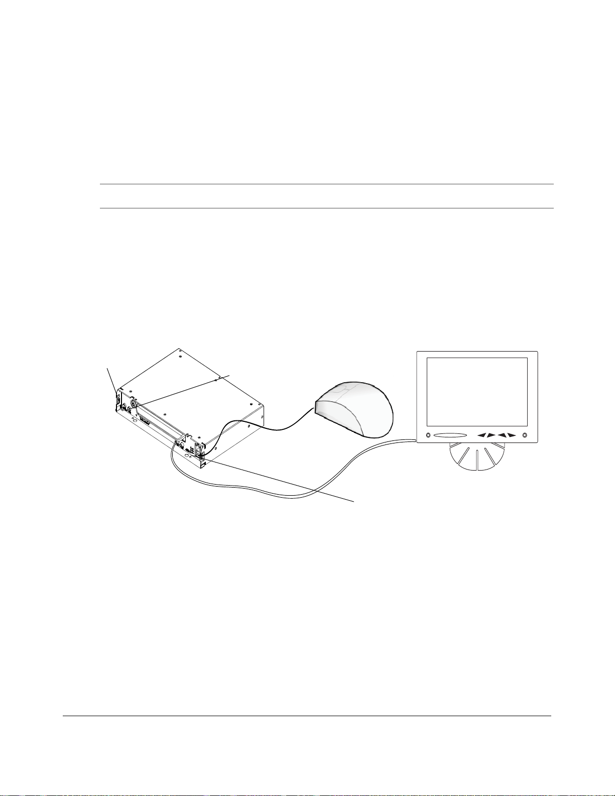
Mouse and Monitor Connected to DVR
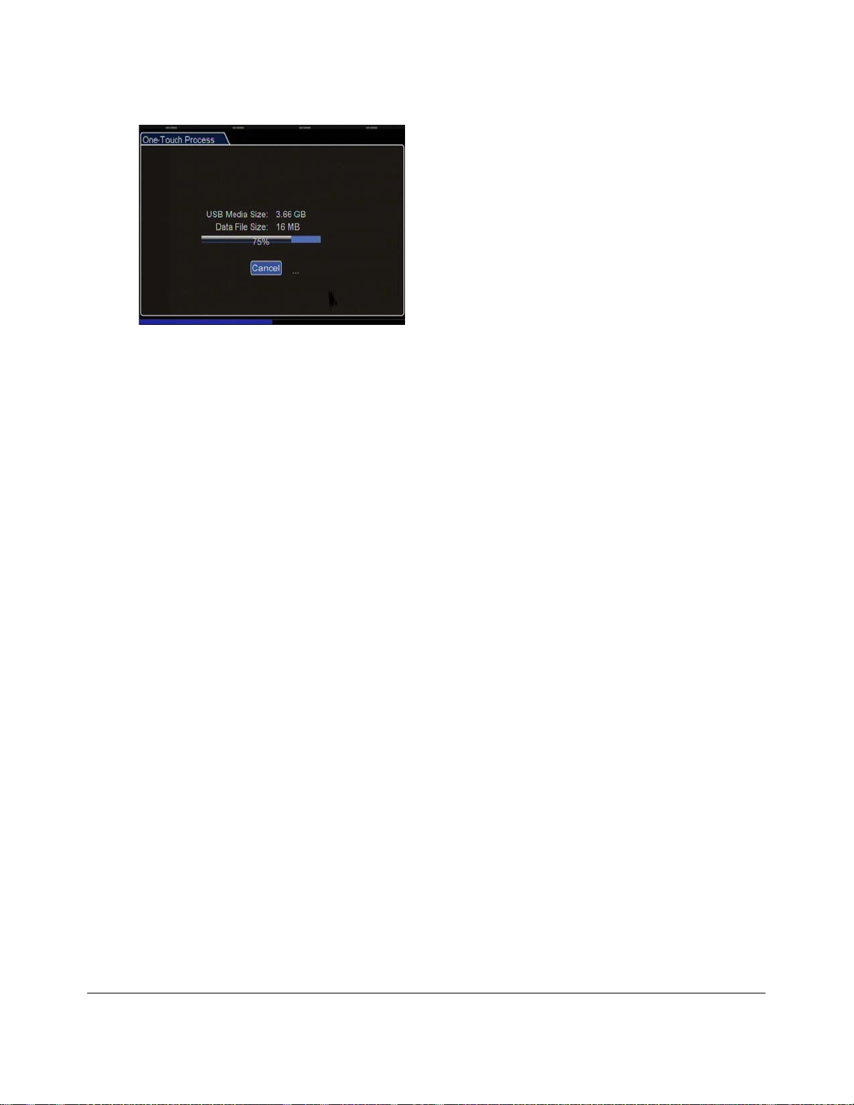
A progress bar moves as the content is downloaded. The screen shows the size of the USB Media
Size and the data file size. The status line of the on-screen display indicates DOWNLOAD.
The information that is downloaded is pre-selected by the settings for one touch download button
behavior.
Page 31
DVR Operation
Figure 2-15
One-Touch Progress
When transfer is complete, the on-screen display closes.
5. Remove the USB drive.
6. To power off the DVR immediately, press STOP/TEMP PWR for five seconds.
The DVR will power off automatically after 5 minutes.
700-0190 R002 2–15
Page 32

DVR Operation
2–16 700-0190 R002
Page 33

vMax Web Remote Operation
This chapter provides information on using vMax Web to remotely access the DX-HD DVR for
viewing live and recorded video and archiving recorded video. This chapter contains the following
sections:
System requirements, on page 3–1
Accessing vMax Web, on page 3–2
vMax Web User Interface, on page 3–4
vMax Web Live Tab, on page 3–5
vMax Web Configuration Tab, on page 3–6
vMax Web Playback Tab, on page 3–7
vMax Web Archive Tab, on page 3–12
Viewing DX-HD Video Archives, on page 3–13
vMax Web Remote Operation
CHAPTER 3
3.1. System requirements
The following minimum system requirements are necessary to access DVRs with vMax Web:
Table 3-1
Computer/Processor
Operating Systems
Web browser
Memory 2GB RAM or more available to the program (4GB or more total) recommended
Disk Space 10GB of available hard-disk space (depending on the amount of video to be stored
Drive CD/DVD writer drive and software if the archives to be stored on CD/DVD media
Minimum System Requirements
•Intel Core® I7 or greater
• High performance video card with DirectX Ver. 10 or higher support
• 1280 × 1024 monitor resolution
• 32 bit color quality
• Sound card and speakers
• USB 2.0
• 1 GBit Ethernet adaptor
®
Windows
versions)
Microsoft .NET Ver. 3 or higher support
Internet Explorer
locally)
XP Service Pack 3, Windows Vista™, or Windows 7 (32-bit and 64-bit
®
, Version 8 or 9 (3 2 bit versions only)
700-0190 R002 3–1
Page 34
vMax Web Remote Operation
3.2. Accessing vMax Web
When the DX-HD DVR is connected to the network, users can remotely access the DVR over the web
to view, playback, and archive video as well as configure the DVR.
CAUTION: System Access Restriction
DVR menu access is restricted to persons with system access permission. If you require
permission to access configuration settings, contact your system administrator.
NOTE: The default network settings allow for connection to a laptop computer for configuration and
usage of the DVR only. For remote network access, consult with your IT staff or Seon Design
to configure the DVR to be on the same sub net as the laptop..
To access vMax Web
1. On a PC with an Ethernet connection to the DVR, right click the Internet Explorer 8 icon and
select Run as Administrator.
Windows may prompt for confirmation.
NOTE: vMax Web is not compatible with 64-bit versions of Internet Explorer. Internet Explorer
should be set to default settings. If firewall security, access restrictions, or custom IE settings
are applied, they may adversely affect vMax Web performance. vMax Web is not compatible
with browsers other than Internet Explorer.
CAUTION: System Access Restriction
It is assumed that archiving is performed by users with administration level login
permissions, and that the computer, network, and Internet Explo rer 8 have been configured to
enable archiving and downloading video files.
If you require permission to access computer, network, and Internet Explorer 8 configuration
settings, contact your system administrator.
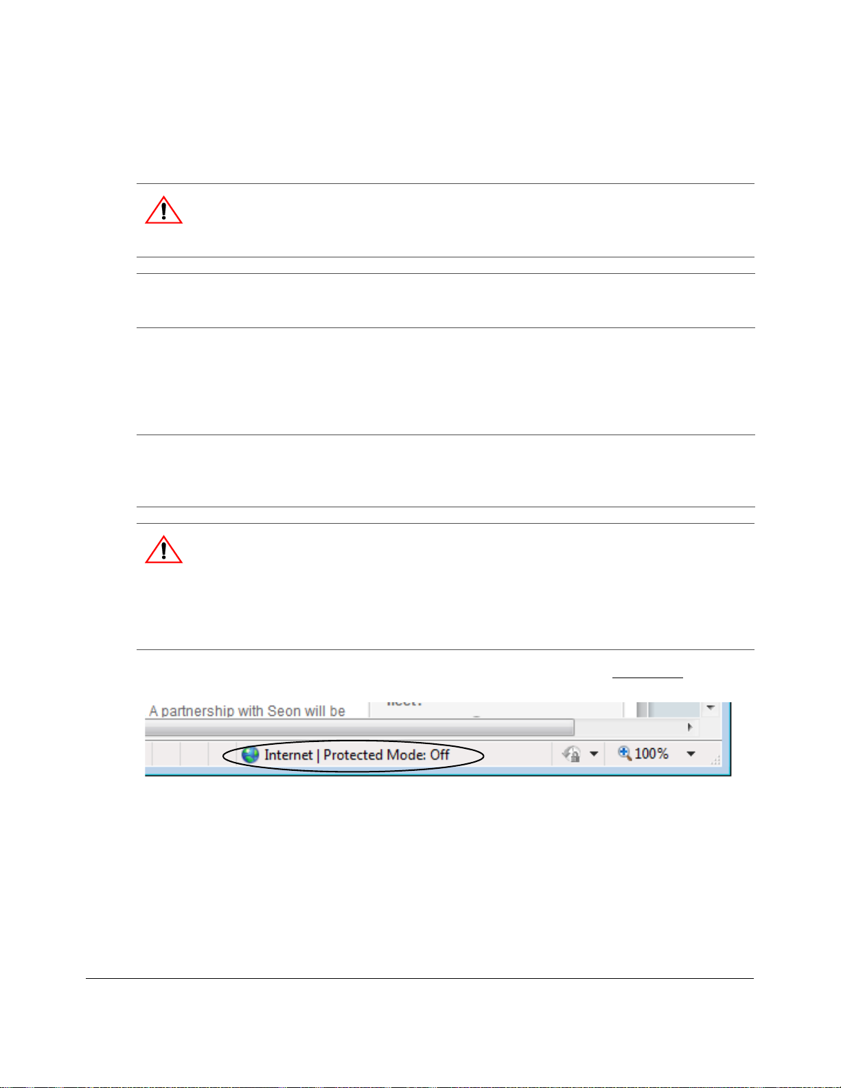
2. Confirm in the browser tray that Protected Mode is set to Off, as shown in Figure 3-1
Figure 3-1
3. In the browser’s URL field, enter the DVR IP address from the Network Settings menu.
Zeroes before value digits need not be entered. For example, enter 092.068.010.002 as 92.68.10.2.
4. Click Enter on the keyboard.
Internet Explorer Protected Mode: Off
.
3–2 700-0190 R002
Page 35
vMax Web Remote Operation
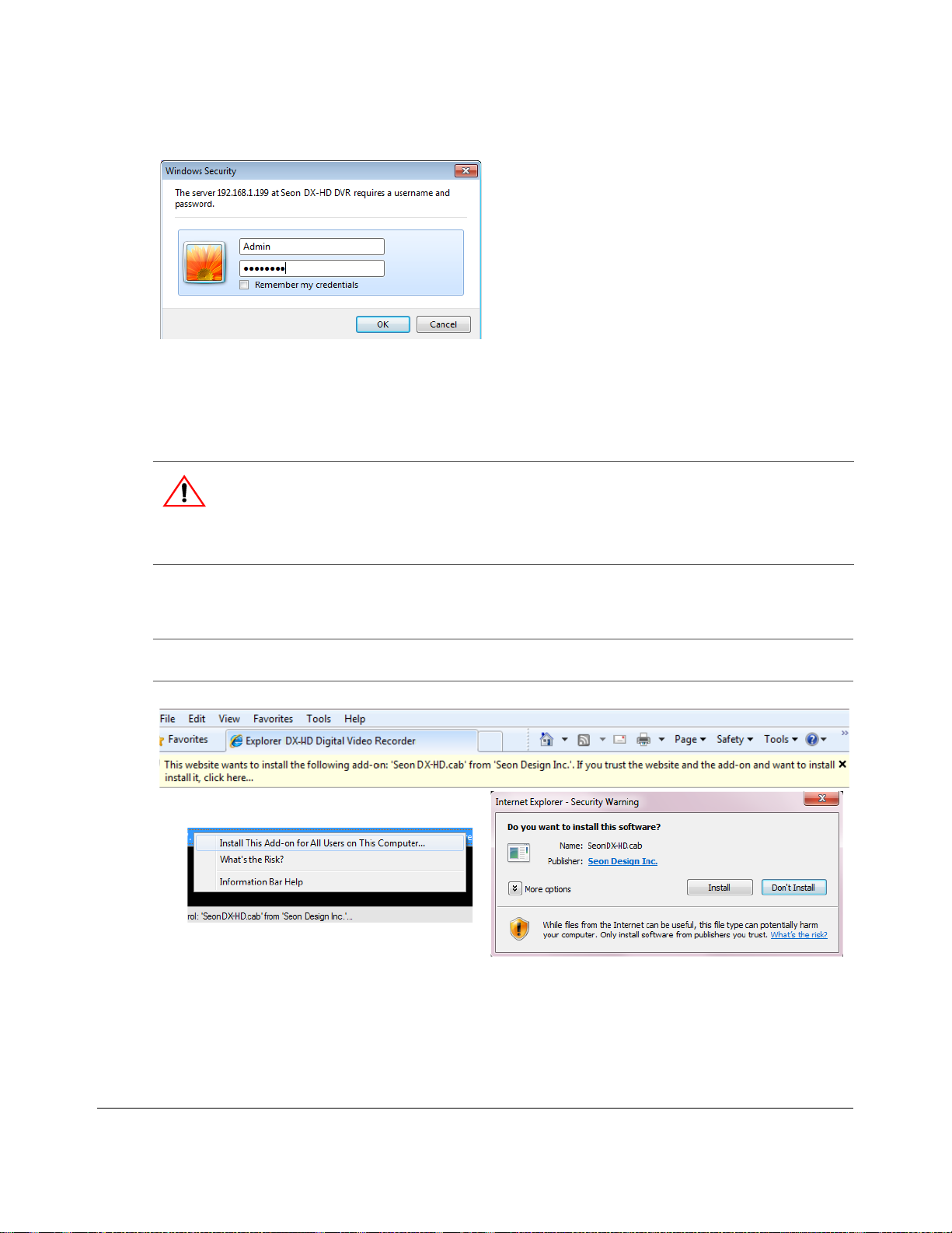
5. At the prompt, enter the user name and password, as shown in Figure 3-2 .
Figure 3-2
vMax Web DVR Login Prompt
The default user name is Admin.
The default password is 11111111.
This login data can be edited in the DVR > Configuration > Network > User Levels menu.
CAUTION: System Access Restriction
DVR user names and passwords are provided by Seon Design with specific permissions
assigned depending on user requirements. If you require permission to access DVRs, contact
your system administrator.
6. Click OK.
vMax Web opens.
NOTE: The first time a computer connects to this model of DVR, users not running in administrator
mode may be prompted to confirm installation, as shown in the following images.
Figure 3-3
700-0190 R002 3–3
Windows Warnings
Page 36
vMax Web Remote Operation
1
2
3
4
6
7
5
3.3. vMax Web User Interface
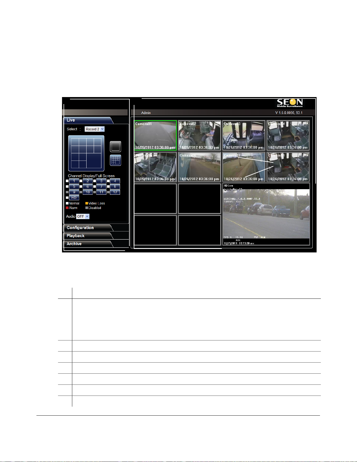
vMax Web opens with the Live tab selected and live video from the DX-HD and cameras displaying.
By default, vMax Web will stay active for 10 minutes after you last used it and then close the
connection to the DVR. If you have a file saving menu open and are downloading an archive, this does
not apply. This vMax Web Timeout time can be adusted in the Configuration tab’s System menu.
Figure 3-4
Table 4 User Interface Components
ID Description
1 Tab area.
2 Viewing Area — view multiple or single cameras and telemetry information
3 User login name
4 DVR firmware version
vMax Web User Interface for DX-HD DVR
• Live tab — live DVR video display and viewing controls
• Configuratio n tab — DVR setup menus
• Playback tab — search recorded DVR video
• Archive tab — archive recorded DVR video
5 Overlay information — DVR configurable; camera title, date and time
6 DVR information — DVR ID, firmware version, and operating status
7 Telemetry information — DVR location, speed, and hard drive temperature
3–4 700-0190 R002
Page 37
3.3.1. vMax Web Live Tab
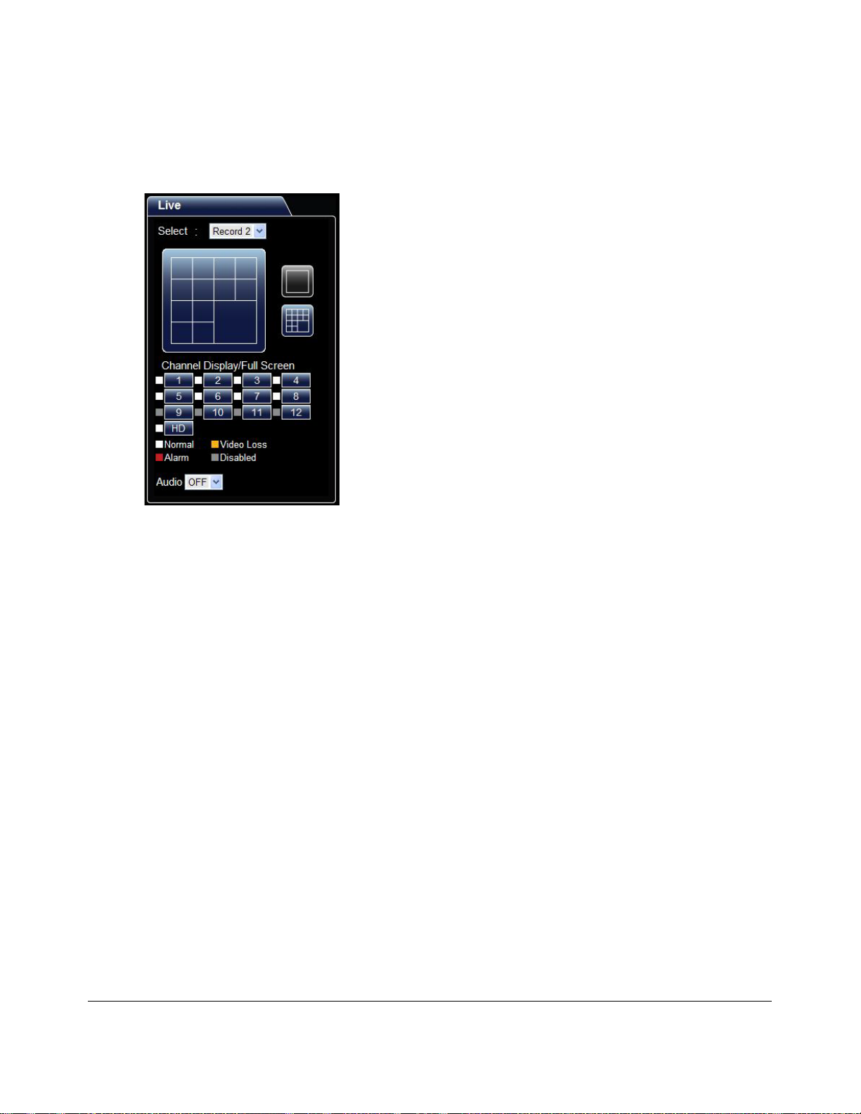
Upon login, vMax Web opens with the Live tab selected, as shown in Figure 3-5 . Users see current
camera output, as shown in Figure 3-4 .
vMax Web Remote Operation
Figure 3-5
Live tab for DX-HD DVR
To setup the Live tab view
1. In the Select drop down menu, select the Record 2 or Record video stream.
The Explorer DX-HD DVR records two streams of video, one for low bandwidth remote viewing,
and one with higher video speed, quality, and resolution settings for creating archives. When
accessing the DVR with vMax Web, the Record 2 video stream is selected for use with low
bandwidth connections while viewing live video.
Higher video speed, quality, and resolution settings will provide clearer pictures and will require
more storage space and longer archiving time. These settings are adjustable in the Configuration
tab's Record menu.
2. Use the Channel Display/Full Screen tools to display all or individual channels.
Each camera’s status is indicated by a color and explained in the color legend below the 12 display
buttons.
3. In the Audio drop down menu, select whether to have the Audio coming from one of the cameras
or off.
700-0190 R002 3–5
Page 38
vMax Web Remote Operation
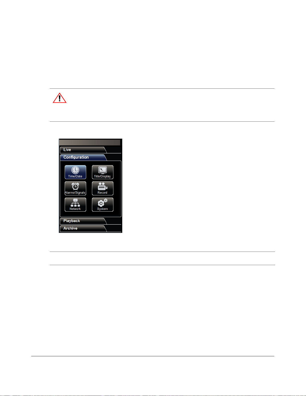
• Time/Date
• Title/Display
• Alarms/Signals
•Record
•Network
•System
3.3.2. vMax Web Configuration Tab
The Configuration tab contains menus specific to DVR features and setting options. Features vary
depending on the DVR model used.
The vMax Web configuration menus are similar to the DVR OSD menus. See the DX-HD DVR
Installation and Configuration Guide, 700-0189 for specific details when configuring DVR function
settings.
CAUTION: System Access Restriction
DVR user names and passwords are provided by Seon Design with specific permissions
assigned depending on user requirements. If you require permission to access DVR
configuration settings, contact your system administrator.
DX-HD DVR setup menus include:
Figure 3-6
NOTE: For each menu selected and edited, click Save in each configuration menu to save the changes
DX-HD DVR Configuration tab
before clicking on other menus.
3–6 700-0190 R002
Page 39
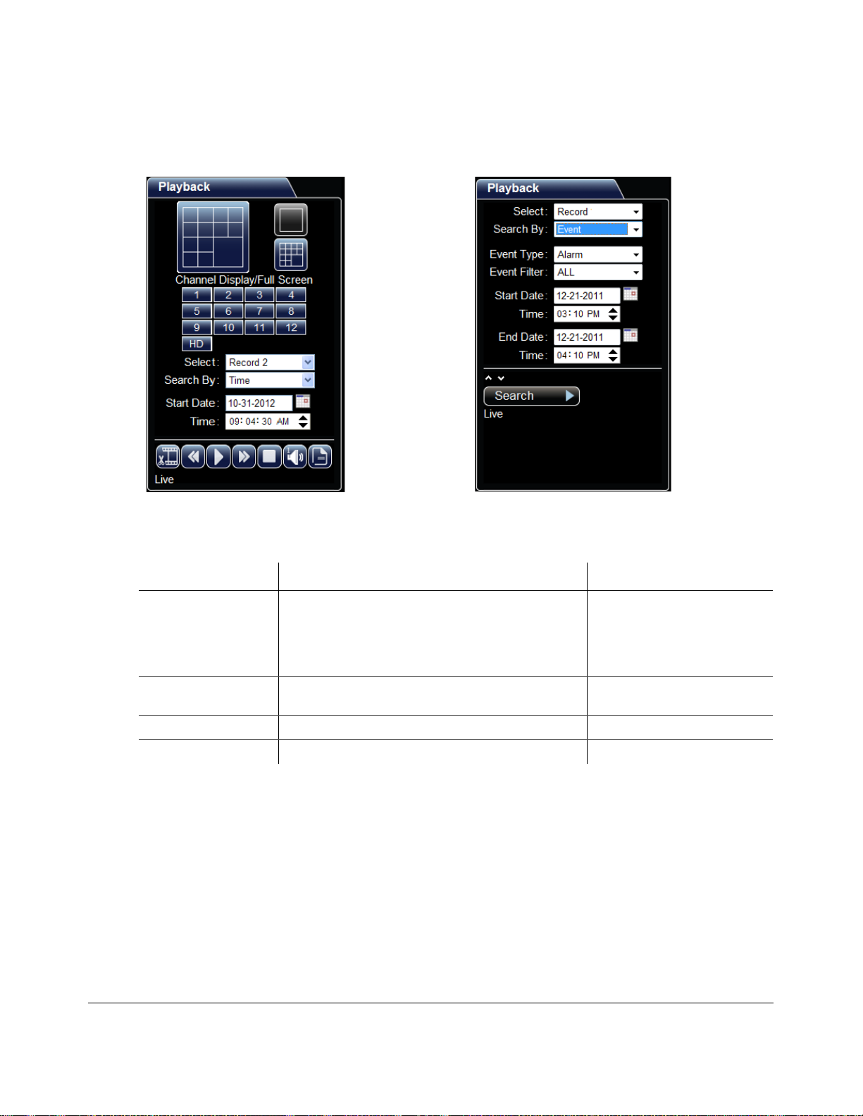
3.3.3. vMax Web Playback Tab
To search the recorded video, select the Playback tab as shown in Figure 3-7 .
vMax Web Remote Operation
Figure 3-7
Table 3-2
Playback tab views, searching by Time or Event
Time Search Fields
Menu Item Description Value [Default]
Select Choose which recording stream to search for video in.
• With Record selected, high resolution video is
available for archiving.
• With Record2 selected, low resolution video is
available for faster searching and remote playback.
Search By Choose whether to search by the time the event occurred
or by specific events.
Start Date Set the start date (month, day, and year) for the search. [Current]
Time Set the start time for the search. [1hour before current time]
Record, [Record2]
[Time], Event
700-0190 R002 3–7
Page 40
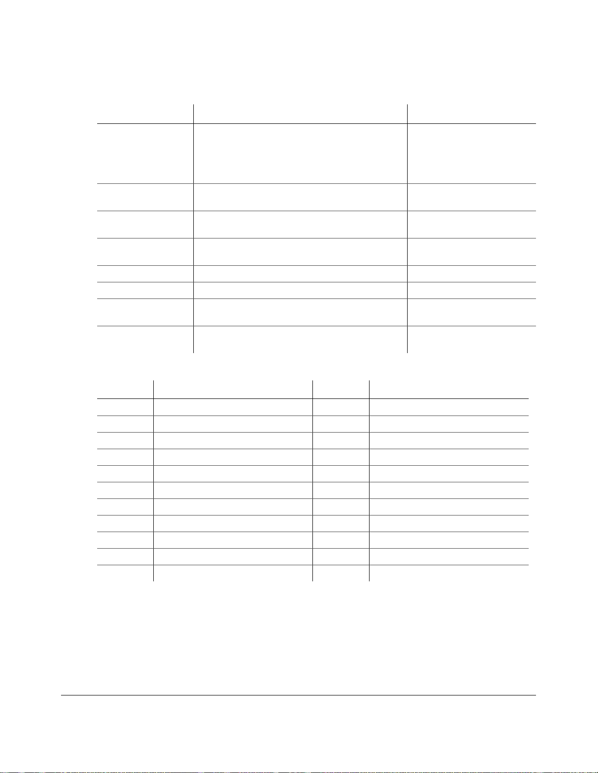
vMax Web Remote Operation
Table 3-3
Event Search Fields
Menu Item Description Value [Default]
Select Choose which recording stream to search for video in.
• With Record selected, high resolution video is
available for archiving.
• With Record2 selected, low resolution video is
available for faster searching and remote playback.
Search By Choose whether to search by the time the event occurred
or by specific events.
Event Type Enabled when Event is selected in Search By. Select the
type of event to search for.
Event Filter Enabled when Event is selected in Search By. Select the
specific alarm to search for.
Start Date Set the start date (month, day, and year) for the search. [Current]
Time Set the start time for the search. [1hour before current time]
End Date Enabled when Event is selected in Search By. Set the end
date (month, day, and year) for the search.
Time Enabled when Event is selected in Search By. Set the end
time for the search.
Table 3-4
DVR Event Descriptions
Record, [Record2]
[Time], Event
[Alarms], Signals, System Events
[ALL], ALM 0, ALM 1, ALM 2,
ALM 3, ALM 4
[Current]
[Current time]
Event Description Event Description
Almn Off Alarm Off GSN Z+ Limit exc ee d ed in Z+
Almn On Alarm On Idle0 Idle limit not exceeded/stopped
EXSpeed Excessive speed occurred Idle1 Idle limit exceeded/stopped
FAN Fan fault IG0 Ignition off
GPS Crossed GPS Fence IG1 Ignition on
GSN Gsensor exceeded limit LIVE DVR changes to live mode
GSN X- Limit exceeded in X- PLoss Power Loss
GSN X+ Limit exceeded in X+ Rec On Normal Recording event
GSN Y- Limit exceeded in Y- RUn Remote User Login n
GSN Y+ Limit exceeded in Y+ Signaln Signal Event n
GSN Z- Limit exceeded in Z- Vlossn Video loss on channel n
3–8 700-0190 R002
Page 41

vMax Web Remote Operation
There are two ways to search the DVR for video:
• by the time an event occurred
• by alarm, signal or system events recorded by the DVR
To Search Video from a Time Point
1. Use the Channel Display/Full Screen tools to display all or individual channels.
Each camera’s status is indicated by a color and explained in the color legend below the 12 display
buttons.
2. In the Select drop down menu, select the Record 2 or Record video stream.
The Explorer DX-HD DVR records two streams of video, one for low bandwidth remote viewing,
and one with higher video speed, quality, and resolution settings for creating archives. When
accessing the DVR with vMax Web, the Record 2 video stream is selected for use with low
bandwidth connections while viewing live video.
Higher video speed, quality, and resolution settings will provide clearer pictures and will require
more storage space and longer archiving time. These settings are adjustable in the Configuration
tab's Record menu.
3. In the Search By drop down menu, select Time.
4. Click the Calendar icon to select a start date.
5. Select the start time of the recorded video to view.
6. Click the Play button.
The DVR begins playback of video from the designated or next available time point.
7. Use the play, pause, fast forward or reverse (up to 32x speed) controls to locate the event video.
8. Note the event start and end date and time for use on the Archive tab.
700-0190 R002 3–9
Page 42

vMax Web Remote Operation
To Search Video from an Event Marker
1. Select Event in the Search By drop down menu.
The Event Type and Event Filter menus appear, as shown in Figure 3-7 .
2. From the Event type menu, select an event type.
3. From the Event Filter menu, select a filter type.
Table 4 Playback tab Event Types and Filter Options
Event Types E vent Filters
Alarms Alarms recorded that occurred within the selected time range are listed. Options
Signals Signals recorded that occurred within the selected time range are listed. Options
System Events Telemetry events recorded that occurred within the selected time range are listed.
include:
• Alarm 0-5 — as set in DVR Configuration menus, depending on DVR type
•ALL — All alarms
include:
• Signal 1-10 — as set in DVR Configuration menus, depending on DVR type
• ALL — All signals
Options include:
• GPS — position data
• Idle — when vehicle idles for longer than configured time, the event is recorded
• G Sensor — when vehicle G Sensor data exceeds preset ranges, the event is recorded
• Speed — when vehicle speed exceeds preset limit, the event is recorded
System events recorded that occurred within the selected time range are listed.
Options include:
• Ignition — when vehicle ignition is engaged, the event is recorded
• Recording — DVR is recording
• Timers — as configured, when vehicle actions exceed preset timer ranges the event is recorded
• Video Loss — when any camera is not detected, the event is recorded
ALL — all recorded telemetry and system events that occurred within the selected
time range are listed
4. Select a search range start and end date and time.
5. Click Search.
The progress bar appears while the events are located on the DVR.
3–10 700-0190 R002
Page 43
vMax Web Remote Operation
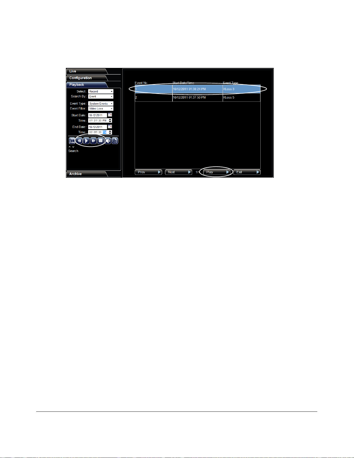
6. From the list that appears in the V iew area, select an event and click Play. Windows may request to
download an Active X control..
Figure 3-8
Playback Event Search Results
7. On the Playba ck ta b are a, us e the play, pause, fast forward or reverse (up to 32x sp eed) contro ls to
locate the video loss event.
When reviewing the event list, you can also click on the first (Archive) playback icon to set the
start and stop time and then archive from here.
8. Using the displayed overlay information, note the specific event start and end date and time for
archiving.
9. Click Stop to return to the Event list, if necessary.
700-0190 R002 3–11
Page 44
vMax Web Remote Operation
3.3.1. vMax Web Archive Tab
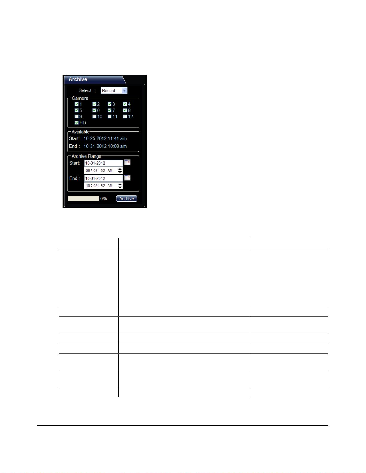
To archive the specific recorded video, select the Archive tab as shown in Figure 3-9 .
Figure 3-9
Table 3-5
Archive tab for DX-HD DVR
Archive Tab Fields
Menu Item Descrip tio n Value [Default]
Select Choose which recording stream to search.
• With Record selected, high resolution video is
available for archiving. (Recommended)
• With Record2 selected, low resolution video is
available for faster searching and remote playback.
(Not recommended)
• With Log File selected, the user can export a log file of
all selected events to a text file.
Camera Select the camera(s) with the required recorded video. 1-12, HD
Available Read only. This area displays the earliest and latest dates
containing recorded video on the DVR drive.
Start Set the start date (month, day, and year) for the archive. [Current]
Time Set the start time for the archive. [1hour before current time]
End Enabled when Event is selected in Search By. Set the end
date (month, day, and year) for the archive.
Time Enabled when Event is selected in Search By. Set the end
time for the archive.
[Record], Record2, Log File
Start, End
[Current]
[Current time]
Archive
Select to save the selected range of video to a file on the PC.
In the Archive tab, the Record video stream is selected to provide the best quality video for the archive
segment.
3–12 700-0190 R002
Page 45

vMax Web Remote Operation
To Archive Video Segments
1. In the Select drop down menu, select the Record video stream.
The Explorer DX-HD DVR records two streams of video, one for low bandwidth remote viewing,
and one with higher video speed, quality, and resolution settings for creating archives. When
accessing the DVR with vMax Web, the Record 2 video stream is selected for use with low
bandwidth connections while viewing live video.
Higher video speed, quality, and resolution settings will provide clearer pictures and will require
more storage space and longer archiving time. These settings are adjustable in the Configuration
tab's Record menu.
2. Select the check box(es) for the camera(s) to archive.
3. In the Archive Range area, select the archive start and end dates and times.
4. Click Archive.
5. In the Save As window, choose a file saving location and enter a file name.
vMax W eb saves archives in the Seon DVR format, preserving all video and telemetry data, which
for security purposes can only be viewed with Seon Design’s vMax View application.
6. Click Save.
The progress bar appears while the archive is being created.
7. In the confirmation dialog, click OK when the archive is complete.
The archive is ready to be viewed with the vMax View archive viewer.
3.3.1.1. Archive Segmentation
Downloaded archives larger than 2 GigaBytes are segmented when downloaded from the DX-HD
DVR. The segments are saved as separate archive files with the following naming convention:
• Archive.avr (original)
• Archive-002.avr (next segment)
• Archive-003.avr (next segment)
If your archive seems too short it could have been segmented.
vMax View has an option to stitch together segmented archive video if required.
3.3.2. Viewing DX-HD Video Archives
View the archive using the vMax View software application. When the application is installed, double
click the archive file to open it in vMax View. See the vMax View User Guide, 700-0137. for detailed
procedures.
700-0190 R002 3–13
Page 46

vMax Web Remote Operation
3–14 700-0190 R002
Page 47
DVR Firmware and Configuration Uploads
DVR Firmware and Configuration Uploads
This chapter provides information and procedures for uploading firmware updates and DVR
configuration files to the DVR.
CAUTION: Administrator Permissions Required
These procedures should only be performed by administrator level staff.
If you have questions about these procedures, contact Seon support.
This chapter contains the following sections:
Firmware Updates, on page 4–2
Configuration Uploads, on page 4–3
USB Memory Device to DVR Configuration Upload, on page 4–3
Uploading Configuration Files to DVR via vMax Web, on page 4–7
CHAPTER 4
For complete configuration settings and menu options, see the Explorer DX-HD Installation and
Configuration Guide, 700-0182.
700-0190 R002
4–1
Page 48
DVR Firmware and Configuration Uploads
4.1. Firmware Updates
The firmware version is displayed on the top right corner of every menu. The firmware update must be
obtained from Seon Design. T o install a firmware update, a USB memory device mu st be formatted by
a Windows®-based computer using the FAT file format. Load the Program Update file onto the USB
memory device.
CAUTION: Equipment damage
Do not remove power while updating the DVR firmware. Equipment damage may result.
To install a firmware update on the DX-HD:
1. Power up the DVR using the vehicle ignition.
2. Insert the USB memory device with the new firmware version into a USB port on the DVR.
3. After the DVR has started, go to the System Settings menu > Program Update.
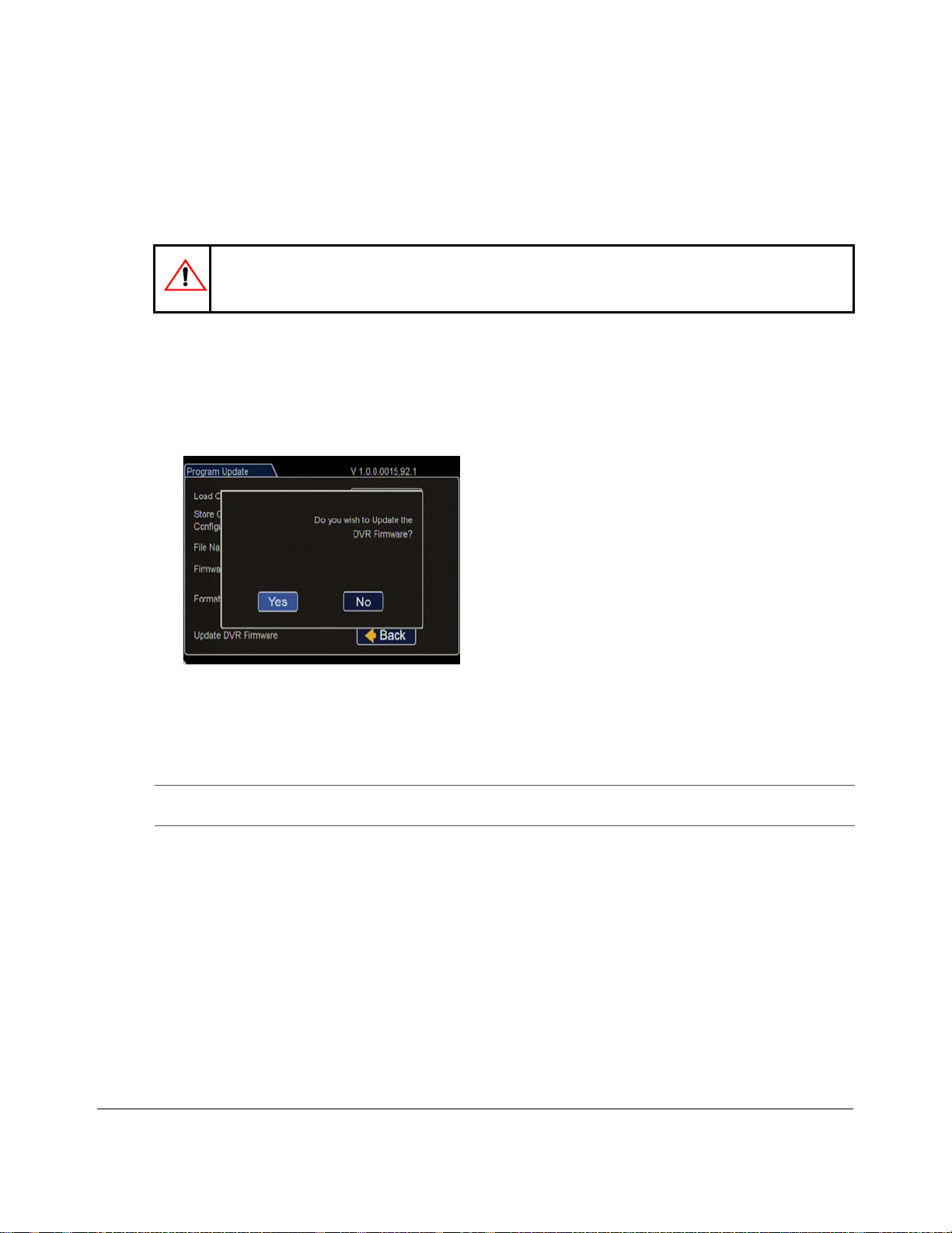
4. Click Update.
Figure 4-1
A window appears asking if you wish to update the DVR firmware.
5. Click Yes to proceed, or No to cancel.
6. Once the update is finished, the DVR will automatically restart.
Important: On restarting, the DVR will take up to 3 minutes to load as it completes the upgrade process.
7. Remove the USB memory device.
Updating DVR Firmware Dialog Box
Wait until the DVR finishes loading.
4–2 700-0190 R002
Page 49
DVR Firmware and Configuration Uploads
4.2. Configuration Uploads
A configuration file is uploaded to a DVR when the DVR is first installed or when settings need to be
changed on multiple DVRs in a fleet.
Configuration files can be uploaded at the DVR with a USB drive or over the network using vMax
Web or vMax Commander applications. Use these procedures upload DVR configuration files.
To upload configurations with vMax Commander, see the the vMax Commander Installation and
Configuration Guide (700-0100).
4.2.1. USB Memory Device to DVR Configuration Upload
This method requires physical access to the DVR and an portable video monitor and trackball USB
mouse.
To load a configuration update to the DVR, the USB memory device must be formatted by a
Windows®-based computer using the FAT32 file format.
To upload a configuration update on the DX-HD via USB:
1. Load the configuration file onto the USB memory device.
2. Copy the configuration file at the root of the USB memo ry device folder.
Important: For USB uploading, the configuration file name can have no more than four
characters. Example: DXHD.seon.
3. Power up the DVR using the vehicle ignition.
4. With the DVR on, connect the portable video monitor and USB mouse.
5. Insert the USB memory device with the new configuration file into the USB port on the DVR.
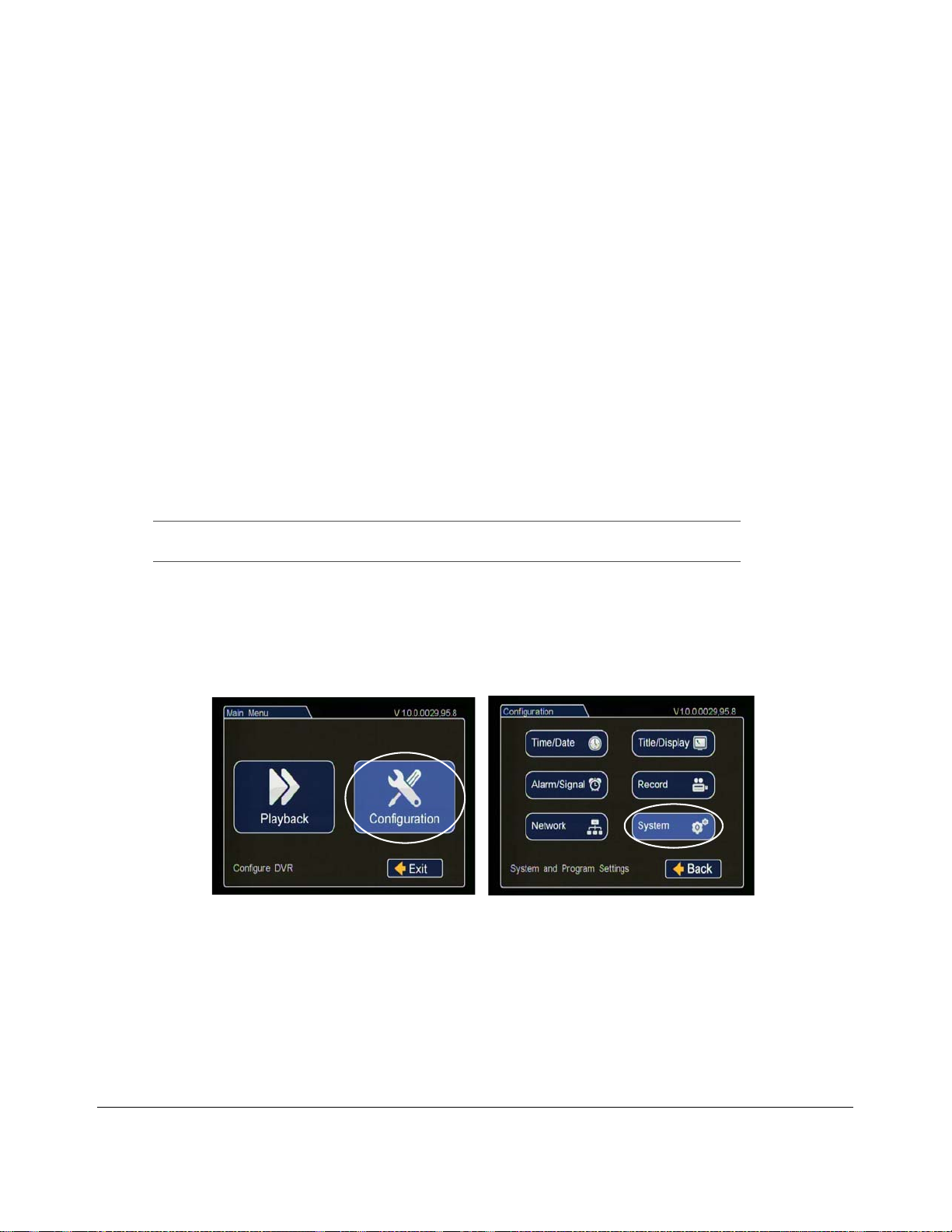
6. In the DVR on screen display, double right click to open the menu, click Configuration, and then
click Network.
Figure 4-2
Main Menu and System Menu
700-0190 R002
4–3
Page 50
DVR Firmware and Configuration Uploads
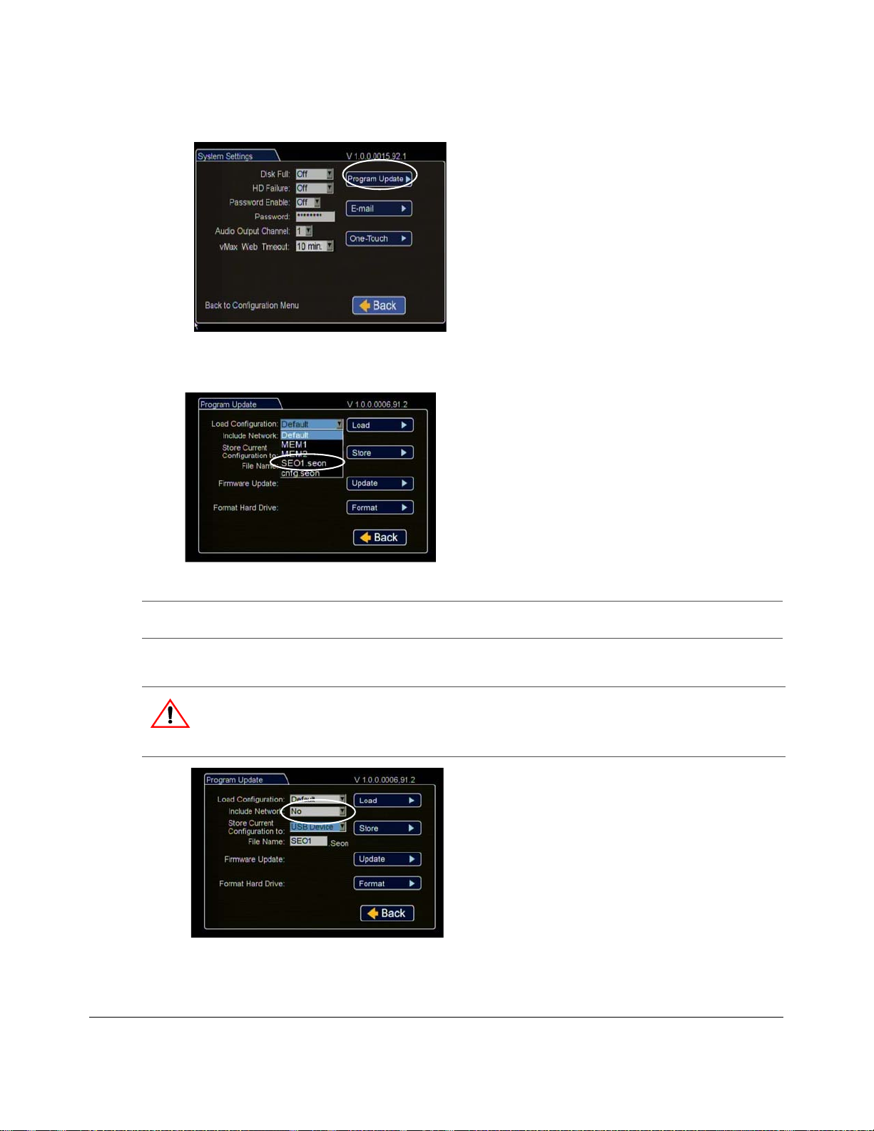
7. In the System Settings menu click Program Update.
Figure 4-3
System Program Update Menu
8. From the Load Configuration menu, select the file to upload.
Figure 4-4
Important: The Load Configuration menu displays only the ten most recent configuration files on the
Select Configuration File
USB drive.
9. From Include Network, select whether or not to overwrite the existing DVR network settings with
the new configuration settings. The default setting of NO keeps your existing network settings.
CAUTION: DVR Communication Disruption Risk
Avoid unintentionally changing the DVR network settings when uploading a new configuration. When
saving or changing network settings, communication with the DVR can be disrupted.
Figure 4-5
4–4 700-0190 R002
Program Update Menu
Page 51
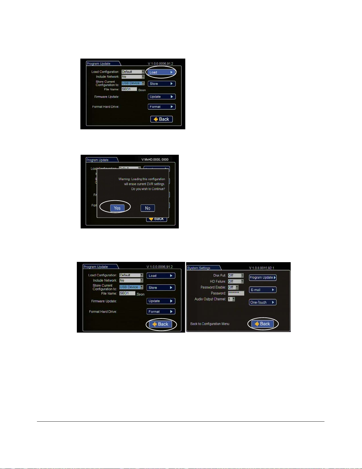
10. Click Load.
DVR Firmware and Configuration Uploads
Figure 4-6
Program Update Menu
A window appears asking if you wish to update the DVR configuration.
Figure 4-7
Load Configuration: Warning Message
11. Click Yes to continue or No to cancel.
12. Click Back in the Program Update and then System Settings menus to save and exit the menus.
Figure 4-8
700-0190 R002
Click Back to Save Configuration
4–5
Page 52
DVR Firmware and Configuration Uploads
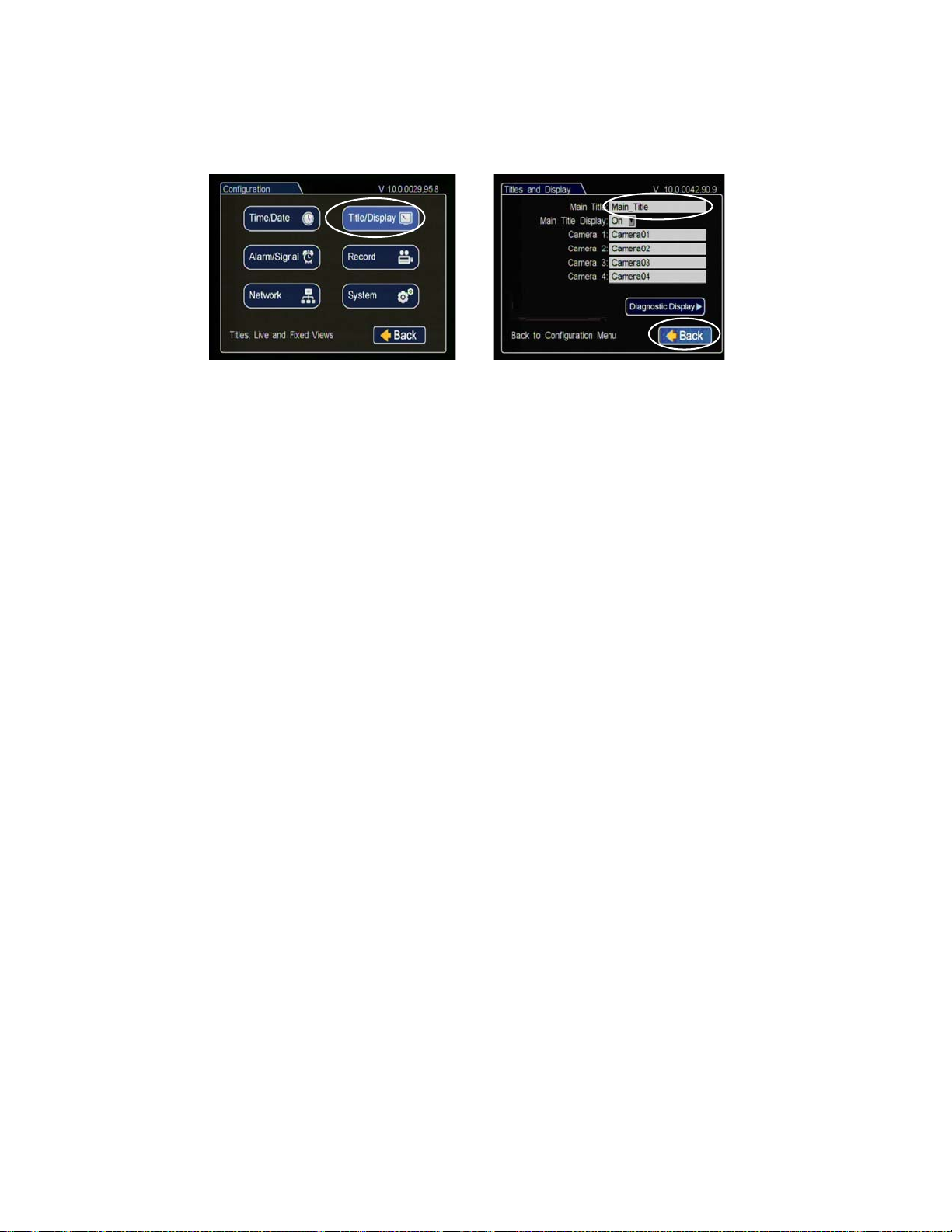
13. From the Configuration menu, click Title/Display, and in the Titles and Display menu, update the
text in the Main_Title field.
Figure 4-9
Titles and Display Menus
14. Click Back to save.
15. Remove the USB memory device.
16. Turn off the DVR, restart the DVR, and confirm that the new configuration settings have been
applied.
4–6 700-0190 R002
Page 53
DVR Firmware and Configuration Uploads
4.2.2. Uploading Configuration Files to DVR via vMax Web
To remotely install a configuration update, the configuration file (received from Seon or created and
saved from a DVR in your network) must be on a computer with network access to the DVR and with
Internet Explorer 8 (32 bit version) to access vMax Web.
To upload a configuration update on the DX-HD via vMax Web:
1. On a computer, copy the DVR configuration file.
2. Power up the DVR using the vehicle ignition.
3. Open Internet Explorer, and in the address bar, type in the DVR IP address.
The default IP address is http://169.254.1.1.
4. The vMax Web login screen appears.
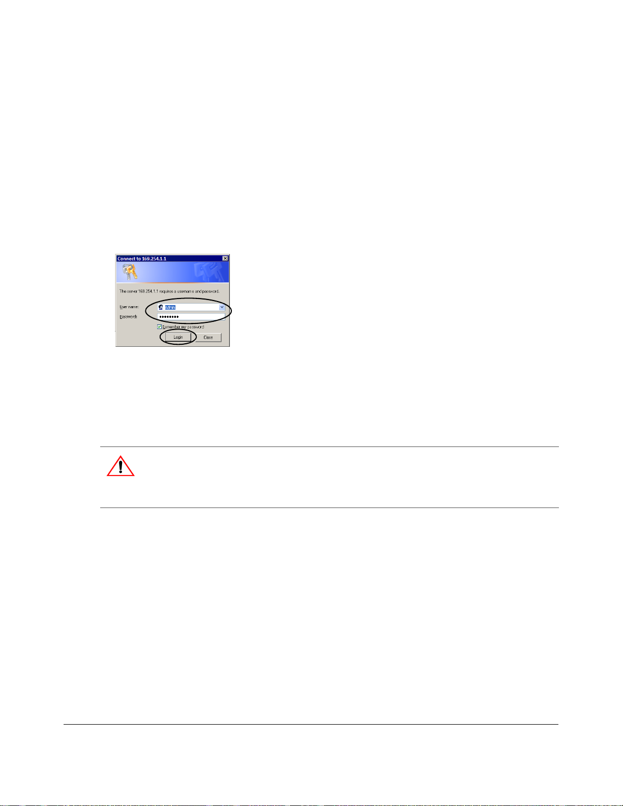
Figure 4-10
Login vMax Web
5. At the login prompt, enter a user name and password to access the internet browser user interface.
User names and passwords are case sensitive.
• Default User name: Admin.
• Default Password: 11111111.
CAUTION: DVR Password Security
The default password is 11111111. For se curity purposes, Seon recommends that the user default login
and system settings passwords should be changed. Seon is not responsible if the password is lost or
forgotten.
700-0190 R002
4–7
Page 54
DVR Firmware and Configuration Uploads
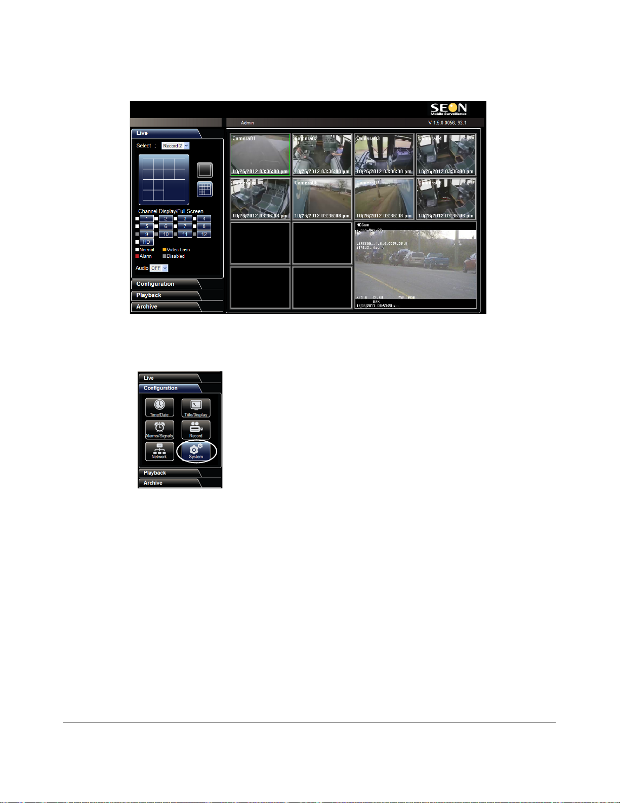
6. Click OK or press Enter on the keyboard to display the vMax Web interface live view screen.
Figure 4-11
vMax Web Live View
7. Select the Configuration Tab.
8. On the Configuration tab, click the System icon.
Figure 4-12
vMax Web System Settings
4–8 700-0190 R002
Page 55
DVR Firmware and Configuration Uploads
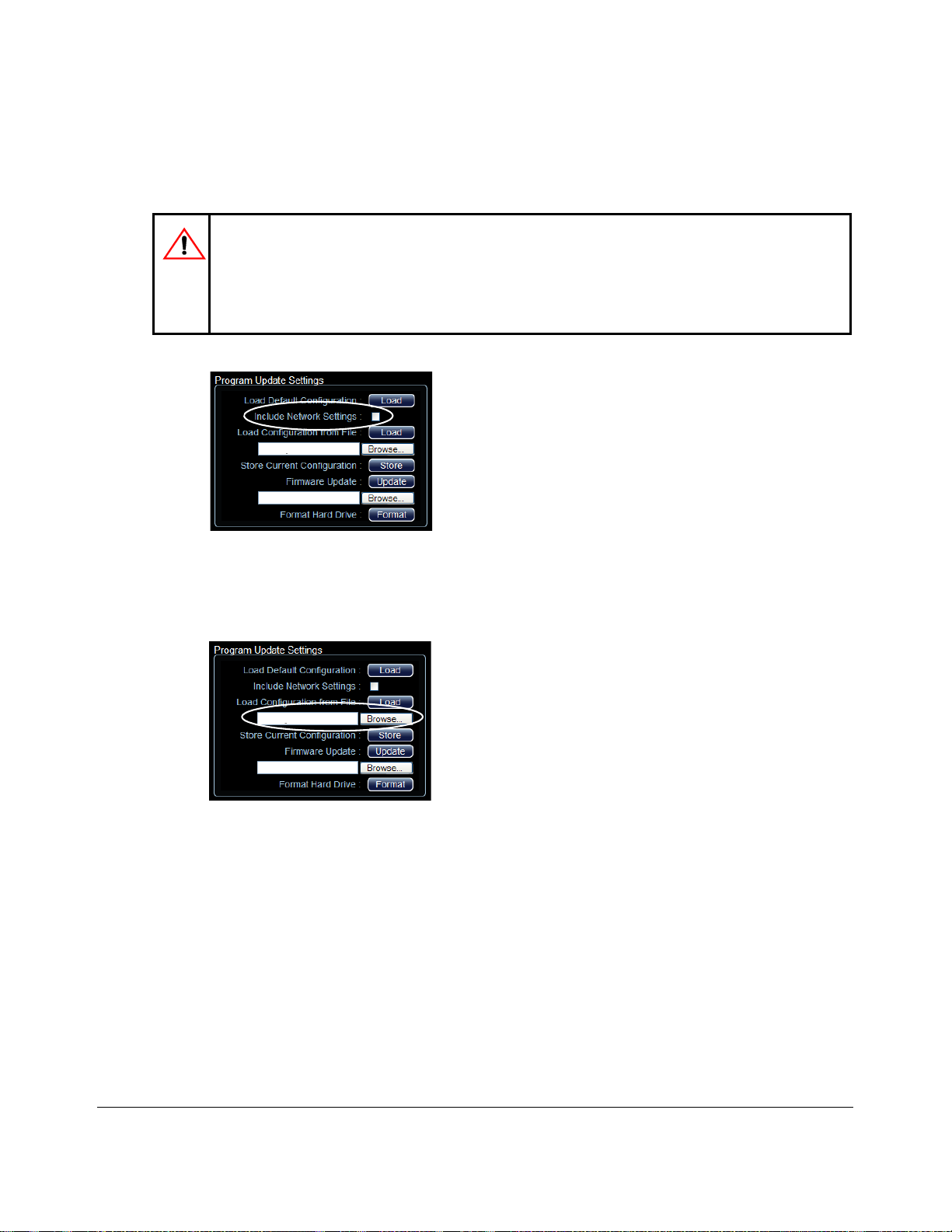
9. In the Program Update Settings area, select the Include Network Settings check box to overwrite
the existing DVR network settings with the new configuration settings. The default (cleared)
setting keeps your existing network settings during the configuration upload.
CAUTION: Risk of Network Settings Loss
Configurations uploaded to the DVR with vMax Web do not get written to the DVR until it powers down
and restarts.
If anyone edits the DVR settings locally after this configuration is uploaded but before the DVR is
restarted, the settings uploaded from vMax Web will be lost.
Figure 4-13
vMax Web System Configuration Program Update Settings
10. In the Program Update Settings area, below the Load Configuration from File field, select Browse
to open the computer search window.
Figure 4-14
vMax Web Program Update Settings
700-0190 R002
4–9
Page 56
DVR Firmware and Configuration Uploads
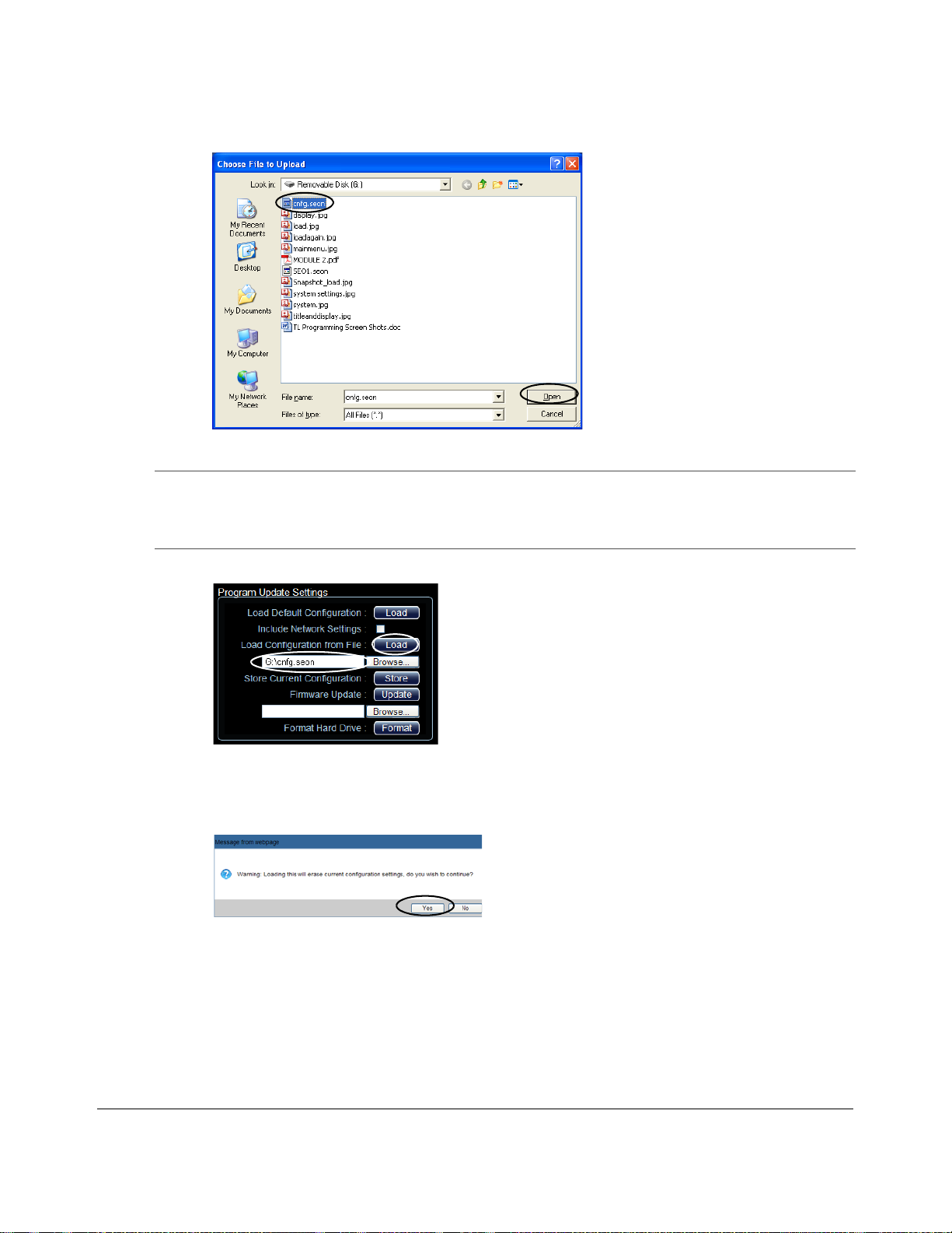
11. In the computer file search window, navigate to the configuration file and click Open.
Figure 4-15
Important: For consistency, Seon recommends that the configuration upload file name should be kept to
Windows File Search
four characters maximum (****.seon) in the event that the file needs to be loaded to the DVR
from the USB port. The DVR USB upload interface supports only four characters in the file
name.
12. The configuration file name and location appear in the location field.
Figure 4-16
vMax Web Load Configuration from File
13. Beside the Load Configuration from File field, click Load.
14. In the Message from web page, click OK to proceed or Cancel to return to the previous menu.
Figure 4-17
Loading Confirmation
15. If necessary, agree to Windows Run Add-On requests.
4–10 700-0190 R002
Page 57
DVR Firmware and Configuration Uploads
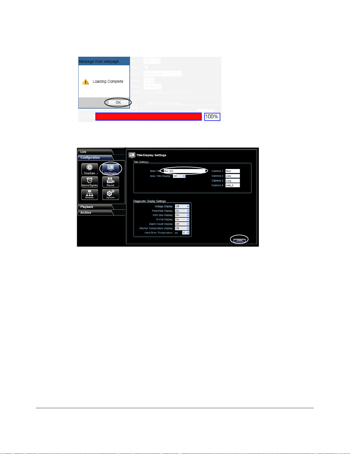
16. When the progress bar shows the update is 100% complete, click OK.
Figure 4-18
Loading Complete
17. In the Titles/Display menu, update the text in the Main_Title field.
Figure 4-19
Titles and Display Menu
18. Click Save to save the settings to the DVR.
19. Power down and restart the DVR.
20. Login with vMax W eb and refresh the vMax Web browser view.
21. Confirm that the new configuration settings are in place.
22. If the DVR’ s IP address has changed as part of the configuration upload, check and set the network
computer’s DVR detection settings accordingly.
700-0190 R002
4–11
Page 58

DVR Firmware and Configuration Uploads
4–12 700-0190 R002
Page 59
Maintenance, Troubleshooting, and Service
Maintenance, Troubleshooting, and Service
This chapter provides information on maintenance, troubleshooting procedures, and returning product
for service.
5.1. Maintenance Tasks
To do this… What to do
CHAPTER 5
Synchronizing the
DVR Clock
Clean the front cover,
cable cover, and DVR
Clean the camera and
window
Replace the fan filter Check the fan filter for excess dirt on a regular basis, and replace the filter
If the system does not have a GPS sensor, synchronize the DVR clock
every six months to ensure accurate video recording of the time and date.
For setting the time and date, see the DX-HD DVR Installation Guide
700-0189.
The DVR, front cover and cable covers are made from 18 gauge steel,
coated with an outdoor powder paint, and only require periodic cleaning.
T o clean, use a damp cloth with a mild detergent. Do not allow water into
the holes.
Refer to the product documentation for cleaning the camera.
when it restricts airflow. Failure to replace a blocked filter may result in
the DVR shutting down on a hot day due to inadequate air circulation.
Contact your dealer or Seon Design to obtain a replacement.
1. Remove the filter cover by gently prying it off with a small flat
screwdriver. Discard the used filter and place a new filter back into
the filter holder.
2. Push the filter cover back into the holder and snap it into place.
CAUTION: Equipment damage
Do not remove the four screws holding the fan in place. Loose components inside the unit could cause
internal damage.
700-0190 R002 5–1
Page 60

Maintenance, Troubleshooting, and Service
5.2. Troubleshooting the DX-HD
The DX-HD is designed for highly reliable operation. However, if you have any problems with your
system, read this chapter. If you cannot resolve the issue, contact Customer Service at Seon Design.
Symptom Possible Cause and Solution
All problems. Many system problems are caused by issues with the power supplied to the DVR. Check the
following:
• The voltage to the system may be too low. Check the voltage display (On or Off) Diagnostic
Display. If the voltage display is turned OFF, go to the Diagnostic Display menu and turn
Voltage Display to ON. The voltage range should be between 8 to 32 VDC.
• The power harness from the DVR must be connected as close to the battery as possible. Check
the wiring to the battery.
• Check the in-line fuses and fuse holders. If a fuse is blown, determine the cause before replacing
it.
The DVR does not
power on.
The DVR turns on
but does not start
recording.
No picture on the
video monitor
output.
The live camera
picture is snowy,
fuzzy, or gr ainy.
The playback
picture is snowy,
fuzzy, or gr ainy.
Vloss event
indicated when all
cameras display
• Is the internal temperature below 40°F (4°C)? The TEMP LED on the front panel will be
flashing.
• Is the constant and switched power harness plugged into the DVR securely?
• Check the ignition wiring from the power input harness. Is the yellow wire connected to an
ignition switched circuit?
• Is the DVR drive installed properly with the key in the locked position on the front panel?
• Is the temperature below 40°F (4°C)? Check the temperature display on the main menu. See the
Diagnostic Display menu. Wait for the DVR to warm up and start recording.
• Is the temperature above 122°F (50°C)? Check the temperature display on the main menu.
• Check the battery voltage.
• Check the settings for Record Delay-On time in the Record menu.
• Are the timers on? See the Timers menu.
• Check the connections inside the camera, as well as the connections inside the DVR cable cover.
• The voltage to the system may be less than 8 VDC. If the status LED on the front panel is
illuminated, the DVR is receiving low voltage.
• Check all connections inside the camera.
• Is the camera cable damaged?
• Check the connections inside the DVR lock box.
• Is the DVR power harness connected directly to the bus battery?
• Is the power input harness connected to the battery?
• Check the video monitor cable attached to the front or back of the DVR.
When A DVR is installed with less than the full complement of cameras connected, unused camera
input settings must be disabled to prevent the DVR from generating Video Loss (VLoss) events for
those camera inputs.
In the DVR Configuration menus, disable unused camera inputs as follows:
• Record Settings menu: Camera Speed OFF, Camera Audio OFF (to save disk space)
• Record 2 Settings menu (DX and MX series DVRs only): Camera Speed OFF
• Alarms/Signals menu: Channel Speed OFF
5–2 700-0190 R002
Page 61

5.3. Returning Product for Service
If any part of the DX-HD DVR is to be returned to Seon Design Inc. for service, contact Seon with the
model and/or serial number of your unit, and ask for a Return Authorization (R A) number which
allows the service technicians to track your product when it comes in for service.
Please have the RA number clearly marked on the outside of the shipping box.
ANY PRODUCT SENT TO SEON DESIGN INC. WITHOUT AN RA NUMBER MAY BE REFUSED.
The contact numbers for Seon Design Inc. are:
Toll Free Telephone 1.877.630.7366
Telephone 604.941.0880
Toll Free Fax 1.866.664.3677
Fax 604.941.0870
Please refer to the Seon Design Inc.® Product W arranty, on page W–1 to review the terms of warranty
service, contact, and shipping information, as well as other important issues regarding the service and
operation of your system.
Maintenance, Troubleshooting, and Service
700-0190 R002 5–3
Page 62

Maintenance, Troubleshooting, and Service
5–4 700-0190 R002
Page 63

Specifications
This appendix provides the product specifications for the Explorer® DX-HD Mobile Digital Video
Recording (DVR) System.
Note: Specifications are subject to change without notice.
A.1. Explorer DX-HD
Video Input/Output 75 Ohm NTSC video
Video Resolution High definition: 1280 x 720 pixels
Video Compression H.264, MJPEG
Media Storage Dual DVR drive, solid state
DVR Drive Removal Hot swappable, locking key-secured
Camera Input Connectors 6-pin Molex
Audio Input Level –8 dBm
Specifications
Appendix A
Analog; 720 × 480, 720 × 240, or 360 × 240 pixels
Audio Output Level –6 dBm, 10 kOhm
Operating Temperature –22°F to 122° F (–30°C to 50°C)
Storage Temperature –40°F to 158°F (–40°C to 70°C)
Operating Humidity 0 to 95% relative humidity, non-condensing
Operating Voltage 8 to 32 VDC
Transient Protection 600 W per signal input, 1.5 kW power input
Temperature Protection Advanced Smart-Temp
Power Harness Connector 4-pin Molex
Alarm Input Connector 2-pin Molex
DVR Drive Dimensions (H × W × D) 0.83 × 3 ×5.1" (21 × 76 × 130 mm)
DVR Dimensions (H × W × D) 2.8 × 11.6 × 10.5" (72 × 294 × 267 mm)
DVR Weight 6.6 lb (3 kg) with front cover, cable cover
Fuses: Power Circuit and Ignition Circuit 5 A and 1 A
Ethernet Gigabit
700-0190 R002 A-1
Page 64
Specifications
A.1.1. Advanced Smart-Temp™
DVR internal temp. Advanced Smart-Temp…
Below –4°F (–20°C) The DVR is not powered, althoug h the DVR drive can still be remo ved from the DVR, heater is
on. If the temperature falls below a preset value wi th the heater on, the DVR shuts down.
Above 149°F (65°C) The DVR shuts down to protect the DVR drive from damage.
A.1.2. Explorer DX-HD Functional Features
Time Format 12-hour or 24-hour format
Date Format mm-dd-yyyy, dd-mm-yyyy and yyyy-mm-dd
Camera Title 8 characters
Repeat Record User selectable On/Off
Record Delay-On and Record Delay-Off 0 seconds to 60 minutes
Power Delay-Off 0 minutes to 4 hours
Daily Timers 10
Alarm 5 Alarm inputs: ALM 0 to ALM 4
Playback Search Date and Time, Ignition, Alarms, or All Events
Playback Speed Image-by-Image, 1×, 2×, 4×, 8×, 16×, 32×, step
USB Memory Device USB 2.0 compatible
A.1.3. Explorer DX-HD Front Cover, Cable Cover
Main Enclosure 18 GA cold rolled steel (CRS), powder-coated black paint
Door Lock Industrial cam lock, keyed alike.
Dimensions (H × W ×D) 2.8 × 11.6 × 10.5 in. (72 × 294 × 267 mm)
A.1.4. Smart-Link™ Module
Power Harness Connector 4-pin Molex
Auxiliary Power Output Connector 2-pin Molex
GPS Input Connector 4-pin Molex
Signals Connector 6-pin Mole x
CAN bus Network Connector 4-pin Molex
Serial Port/GPS 9-pin DB9
Alarm Input Connector 8-pin Molex
Indicator Panel Connector 5-pin Molex
Speed Input Connector 3-pin Molex
Dimensions (H × W ×D) 5.88 × 3.25 × 0.88" (150 × 83 × 23 mm)
Weight and material 9 oz (255 g), steel, powder-coated black paint
A–2 700-0190 R002
Page 65
Legal Notice
Legal Notice
Seon Design® Inc.
Seon Design Inc. is a specialist in the design and manufacture of video surveillance systems for mobile applications. Seon
has been the preferred solutions provider for the pupil transportation industry since 1999. Today, we are proud that our
success in this area has made us the leading manufacturer of mobile video surveillance systems in North America.
Contact Information
Seon Design Inc., Unit 111, 3B Burbidge Street, Coquitlam, BC Canada V3K 7B2
Telephone 604.941.0880 Toll Free Telephone 1.877.630.7366
Fax 604.941.0870 Toll Free Fax 1.866.664.3677
Email [email protected] Web site www.seon.com
Seon Design Inc. Trademarks
Seon Design Inc. holds the following trademarks:
Rogue™, Rogue™ Plus, Explorer®, and Trooper® are registered trademarks of Seon Design Inc.
“Seon Design” is a registered trademark of Seon Design Inc. The Seon logo ( ) is a registered trademark of Seon
Design Inc.
In this User Manual there are references to trademarks, registered trademarks, and product names not owned by Seon
Design Inc. that are the property of their respective owners. They are used in this User Manual for identification purposes
only.
User Manual Revision
This is the R002 revision for this User Manual and is copyright, November 2012 of Seon Design Inc. All rights reserved.
Exclusion of Liability
SEON DESIGN INC.:
(a)
MAKES NO REPRESENTATION, WARRANTY, GUARANTEE OR COVENANT, EXPRESS OR IMPLIED, AS TO THE ACCURACY,
SUFFICIENCY OR SUITABILITY OF ANY TECHNICAL OR OTHER INFORMATION PROVIDED IN THIS USER MANUAL OR ANY
OTHER USER OR OTHER MANUAL OR OTHER DOCUMENTATION PROVIDED BY SEON DESIGN INC. WITH RESPECT TO THE
PRODUCT(S) DESCRIBED HEREIN, INCLUDING WITHOUT LIMITATION ANY DESCRIPTION OF GOODS OR SERVICES,
SPECIFICATIONS, MODELS, DRAWINGS, OR DIAGRAMS.
(b)
DOES NOT ASSUME AND SHALL NOT BE SUBJECT TO AND DISCLAIMS ANY AND ALL RESPONSIBILITY AND/OR LIABILITY
FOR LOSSES, DAMAGES, COSTS OR EXPENSES ARISING OUT OF BREACH OF CONTRACT OR OF WARRANTY, TORT (INCLUDING
NEGLIGENCE AND STRICT LIABILITY) OR OTHERWISE, WHETHER SPECIAL, DIRECT, INDIRECT, CONSEQUENTIAL,
INCIDENTAL, SPECIAL OR CONTINGENT, WHICH MIGHT ARISE OUT OF THE USE OF SUCH INFORMATION. THE USE OF ANY
SUCH INFORMATION WILL BE ENTIRELY AT THE USER’S RISK; AND
(c) EXPRESSLY DISCLOSES THAT IF THIS MANUAL IS WRITTEN IN ANY LANGUAGE OTHER THAN ENGLISH, THAT ALTHOUGH
SEON DESIGN INC. HAS USED REASONABLE CARE TO MAINTAIN THE ACCURACY OF THE TRANSLATION FROM THE ENGLISH
LANGUAGE, THE ACCURACY OF SUCH TRANSLATION IS NOT GUARANTEED OR WARRANTED BY SEON DESIGN INC. PLEASE
REFER TO THE ENGLISH LANGUAGE VERSION OF THIS USER MANUAL FOR APPROVED SEON CONTENT. THE ENGLISH
LANGUAGE VERSION IS AVAILABLE UPON REQUEST FROM THE SEON CUSTOMER SERVICE DEPARTMENT.
Please refer to the Seon Design Inc. Product Warranty applicable to the Product(s) described in this User Manual which
exclusively sets forth Seon Design Inc.’s entire liability arising from or in connection with such product(s) and their use
and the exclusive remedies available for purchasers and users thereof.
Document Number
This User Manual is valid for Seon Design Inc. Document Number 700-0190.
Printed in Canada
700-0190 R002 L-1
Page 66

Legal Notice
L–2 700-0190 R002
Page 67

Seon Design Inc.® Product Warranty
Seon Design Inc. (Seon) warrants the cameras and components listed below against defects in workmanship and materials provided that such
defects appear or are discovered within the respective periods specified below and provided further that the purchaser of such products notifies
Seon of such defects within thirty (30) days of the appearance or discovery of such defects:
• Three (3) years from date of purchase, parts and labor on all Cameras
• Three (3) years from date of purchase, parts and labor on the Explorer® Premier, DX, TX, EX, MX, and Trooper® TL series mobile DVR
Systems
• One (1) year from date of purchase, parts and labor on the Smart Reach® Wireless systems and other Wireless products
• One (1) year from date of purchase, parts and labor on the VML Controller an d other vMax Live Plus hardware products
• One (1) year from date of purchase, parts and labor on all other products and accessories
All service/replacement parts and repairs are warranted for a period of 90 days.
Subject to the terms and conditions listed below, during the relevant warranty period, Seon will repair, replace, or refund the purchase price for the
defective product, whichever Seon considers to be appropriate in the circumstances, in Seon’s sole and arbitrary opinion, free of charge, any
defective products returned prepaid. In the event purchaser has a problem with any Seon product, please call and request a
AUTHORIZATION
(RA) NUMBER from the Service Department. Please call 877-630-7366 or (604) 941-0880 and ask for the Service Department. Be
sure to have the model number, serial number and the nature of the problem available for the customer service representative. Prior authorization
MUST be obtained for all returns, exchanges, or credits. ITEMS SHIPPED TO SEON WITHOUT A CLEARLY IDENTIFIED RA NUMBER MAY BE
REFUSED
.
Products returned will be tested to verify the defect. Upon verification of the defect, the product will be repaired or exchanged, or the purchase
price will be refunded or credited to the customer’s account, at the sole option of Seon. In the event of replacement, the returned product will be
credited to the customer’s account and a new invoice issued for the replacement item. Seon reserves the right to refund the purchase price or to
issue a credit only in lieu of replacement. Seon may use new or refurbished replacement parts for repairing its products, at its sole and arbitrary
discretion. Seon may replace an entire unit with an equivalent model, at its sole and arbitrary discretion. If a unit is exchanged, the returned product
shall become the property of Seon and the exchange product becomes the pr op erty of th e purchaser, and the remainder of the warranty that applied
to the original unit purchased shall apply to the exchanged product. E xchange units may be new units or units that have been repaired to full factory
specifications at Seon’s discretion. If the product is found to be in good working order or its inability to function properly is not covered by this
warranty, the product will be returned in the same condition as received unless repair is possible and requested by the customer. Repa irs o f s uch
nature will incur a charge for parts and labor and will proceed only by agreement with the customer to accept the charge.
This warranty shall not apply:
(a) to equipment not supplied by Seon;
(b) to equipment, including, any components, which shall have been operated in excess of rated capacity , subject to negligence, accident, or
damage by circumstances beyond Seon’s con trol, or to improper installation, operation, maintenance, servicing, alterations or storage,
modification without Seon’s written authorization, misuse, vandalism, fire, floods or acts of nature so as, in Seon’s exclusive and
arbitrary judgment, to affect the same adversely;
(c) if the serial number for the product has been altered in any way; or
(d) if the product has been operated outside of the specified Operating Environment specified in the Seon Users Manual for such product.
RETURN
Disclaimer
THIS WARRANTY IS EXCLUSIVE AND IN LIEU OF ALL OTHER REPRESENTATIONS, WARRANTIES, GUAR ANTEES AND CONDITIONS, EXPRESS OR
IMPLIED
, STATUTORY OR OTHERWISE AND WITHOUT LIMITING THE GENERALITY OF THE FOREGOING, SEON EXPRESSLY DISCLAIMS AND
EXCLUDES
WARRANTIES
Any description of the goods or services, whether in writing or made orally by Seon or Seon’s agents, specifications, samples, models, bulletins,
drawings, diagrams, engineering sheets or similar materials used in connection with customer’s order are for the sole purpose of identifying the
goods and/or services and shall not be construed as an express warranty. Any suggestions by Seon or Seon’s agents regarding use, applications or
suitability of the goods and/or services shall not be construed as an express warranty u nless con firmed to be such in writing by Seon. Purchaser
assumes full responsibility for selecting products to achieve purchaser’s intended purposes, for properly installing and using those products, and
for verifying the results obtained therefrom.
PURCHASER’S EXCLUSIVE REMEDY AND SEON’S ENTIRE LIABILITY ARISING FROM OR IN CONNECTION WITH PURCHASER’S USE OF THE
PRODUCTS
PURCHASE
OR
CLAIMS
SERVICES
INCIDENTAL, SPECIAL AND CONTINGENT DAMAGES WHATS OEVER, EVEN IF SEON HAS BEEN SPECIFICALLY ADVISED OF THE POSSIB ILITY OF
SUCH
700-0190 R002 W–1
ANY IMPLIED WARRANTY OF MERCHANTABILITY, DURABILITY OR F I TNES S FOR PURPOSE AND ANY WARRANTIES OR MODIFIED
ARISING FROM USAGE OF TRADE OR COURSE OF DEALING.
AND/OR THIS AGREEMENT SHALL BE RE P AIR OR REP LACEM E NT OF DEFECTIVE PRODUCTS, OR RE FUND OR CREDIT OF THE
PRICE OF THE PRODUCTS AS SET FORTH ABOVE. SEON SHALL NOT BE SUBJECT TO AND DISCLAIMS: (A) ANY OTHER OBLIGATIONS
LIABILITIE S ARISING OUT OF BREACH OF CONTRACT OR OF WARRANTY, (B) ANY OBLIGATIONS WHATSOEVER ARISING FROM TORT
(INCLUDING NEGLIGENCE, AND STRICT LIABILITY) OR ARISING UNDER OTHER THEORIES OF LAW WITH RESPECT TO GOODS SOLD OR
RE ND E RED BY SEON, OR ANY UN DERTAKINGS, ACTS OR OMISSIONS RELATING THERETO, AND (C) ALL CONSEQUENTIAL,
DAMAGES.
Page 68

Seon Design Inc.® Product Warranty
Without limiting the generality of the foregoing, Seon specifically disclaims any liability for property or personal injury damages, penalties,
special or punitive damages, damages for lost profits or revenues, loss of use of goods or any associated equipment, cost of capital, cost of
substitute goods, facilities or services, down-time, shut-down or slow-down costs, or for any other types of economic loss, and for claims of
customer’s customers or any third party for any such damages. Some jurisdictions do not allow limitation or exclusion of incidental or
consequential damages, so this limitation or exclusion may not apply to purchaser. In no event shall Seon’s total liability for any damages to
purchaser or any other person in connection with the pr odu cts or this agreement exceed the lower of the suggested list price or the actual price paid
for the products, regardless of whether such liability arises from contract, tort, warranty or any other form of claim.
If any provision of this agreement is found to be void, invalid, or unenforceable, that finding shall not affect the remaining provisions, all of which
shall be enforced to the full extent permitted by law. If any remedy hereunder is determined to have failed of its essential purpose, the limitations of
liability and exclusion of damages set forth above shall remain in full force and effect. This agreement may be modified only in writing signed by
a duly authorized representative of Seon.
Provisions Applicable to American Customers
For those customers whose mailing address is in the United States, Seon’s of fer and any agreement of sale resulting therefrom shall be go verned b y
and construed in accordance with the internal and domestic laws of the State of
thereof. The Superior Court of Washington for Whatcom County and U.S. District Court for the Western District of Washington (“the U.S. Closed
Courts”) shall have exclusive jurisdiction to entertain and determine all disputes and claims, whether for specific performance, injunction,
declaration or otherwise arising out of or in any way connected with the construction, breach, or alleged, threatened or anticipated breach of the
contract resulting from this offer and shall have jurisdiction to hear and determine all questions as to the validity, existence or enforceability
thereof. Customer specifically consents to such Court’s exercise of jurisdiction over it. The purchaser attorns to the exclusive jurisdictions of the
jurisdiction of the U.S. Closed Courts, waives any obligation to venue in any action or proceeding regarding Seon Products and waives any
objection that the U.S. Closed Courts are an inconvenient forum or do not have jurisdiction over the purchaser of Seon. The United Nations
Convention On Contracts For The International Sale Of Goods shall not apply.
WASHINGTON without giving effect to the conflict of laws rules
Provisions Applicable to Canadian Customers
For those customers whose mailing address is in Canada, Seon’s offer and any agreement of sale resulting therefrom shall be governed by and
construed in accordance with the internal and domestic laws of the Province of
without giving effect to the conflict of laws rules thereof. The courts of British Columbia (the “Canadian Closed Courts”) shall have exclusive
jurisdiction to entertain and determine all disputes and claims, whether for specific performance, injunction, declaration or otherwise arising out of
or in any way connected with the construction, breach, or alleged, threatened or anticipated breach of the contract resulting from this offer and shall
have jurisdiction to hear and determine all questions as to the validity, existence or enforceability thereof. The purchase r attorns to the exc lusive
jurisdictions of the jurisdiction of the Canadian Closed Courts, waives any obligation to venue in any action or proceeding regarding Seon Products
and waives any objection that the Canadian Closed Courts are an inconvenient forum or do not have jurisdiction over the purchaser of Seon. The
United Nations Convention On Contracts For The International Sale Of Goods shall not apply.
BRITISH COLUMBIA and the laws of C anada applicable therein
W–2 700-0190 R002
Page 69

Page 70
Seon Design Inc.
Unit 111, 3B Burbidge Street
Coquitlam, BC
Canada V3K 7B2
Telephone
Toll Free Telephone
Fax
Toll Free Fax
Email [email protected]
Web site www.seon.com
700-0190 R002
604.941.0880
1.877.630.7366
604.941.0870
1.866.664.3677
Printed in Canada
 Loading...