

Page 1

BACnet Protocol Guide
0A
10/10/2014
Initial Release
---
0B
10/13/2014
Updated PICS for firmware revision 1.0.1
---
0C
10/30/2014
Updated PICS for firmware revision 1.0.3
---
0E
2/12/2016
Updated PICS for firmware revision 1.0.5
---
AQ Series
Senva Sensors
9290 SW Nimbus Ave
Beaverton, OR 97008
154-0012-0E
Rev. Release Date Description of Change ECR
0D 4/17/2015 Updated PICS for firmware revision 1.0.4 ---
Copyright ©2016. All rights reserved. This document contains Senva Sensors proprietary
information, and may not be reproduced or distributed without written permission.
Page 2

Contents
Protocol Implementation Conformance Statement ................................................................................... 4
Auto Configuration ....................................................................................................................................... 5
Device ............................................................................................................................................................ 6
Analog Inputs ................................................................................................................................................ 7
AI 0 Temperature ................................................................................................................................................................... 7
AI 1 Temperature (unsmoothed) ..................................................................................................................................... 7
AI 2 Minimum Temperature .............................................................................................................................................. 7
AI 3 Maximum Temperature .............................................................................................................................................. 7
AI 4 Relative Humidity .......................................................................................................................................................... 7
AI 5 Relative Humidity (unsmoothed)............................................................................................................................ 8
AI 6 Minimum Relative Humidity ..................................................................................................................................... 8
AI 7 Maximum Relative Humidity .................................................................................................................................... 8
AI 8 Dew Point Temperature ............................................................................................................................................. 8
AI 9 Dew Point Temperature (unsmoothed) ............................................................................................................... 8
AI 10 Minimum Dew Point Temperature ........................................................................................................................ 8
AI 11 Maximum Dew Point Temperature........................................................................................................................ 8
AI 12 CO2 Concentration ....................................................................................................................................................... 8
AI 13 CO2 Concentration (unsmoothed)......................................................................................................................... 9
AI 14 Minimum CO2 Concentration .................................................................................................................................. 9
AI 15 Maximum CO2 Concentration ................................................................................................................................. 9
AI 16 User Set Point ................................................................................................................................................................. 9
AI 17 Minimum User Set Point............................................................................................................................................. 9
AI 18 Maximum User Set Point ............................................................................................................................................ 9
Analog Values ............................................................................................................................................. 10
AV 0 MAC Address ................................................................................................................................................................. 10
AV 1 Device Uptime .............................................................................................................................................................. 10
AV 2 Device Restart Count ................................................................................................................................................. 10
AV 3 Display Contrast........................................................................................................................................................... 10
AV 4 Display Rotate Time ................................................................................................................................................... 10
AV 5 Temperature Calibration Slope ............................................................................................................................. 11
AV 6 Temperature Calibration Offset ............................................................................................................................. 11
AV 7 Temperature Response Time.................................................................................................................................. 11
AV 8 Relative Humidity Calibration Slope .................................................................................................................... 11
AV 9 Relative Humidity Calibration Offset ................................................................................................................... 11
AV 10 Relative Humidity Response Time ........................................................................................................................ 11
AV 11 Dew Point Calibration Slope ................................................................................................................................... 12
AV 12 Dew Point Calibration Offset .................................................................................................................................. 12
AV 13 Dew Point Response Time ....................................................................................................................................... 12
AV 14 CO2 Calibration Slope ............................................................................................................................................... 12
AV 15 CO2 Calibration Offset .............................................................................................................................................. 12
AQ Series BACnet Protocol Guide Page 2 of 20 154-0012-0E
Page 3

AV 16 CO2 Response Time ................................................................................................................................................... 12
AV 17 CO2 Auto Calibration Period .................................................................................................................................. 12
AV 18 CO2 Auto Calibration Target .................................................................................................................................. 13
AV 19 CO2 Auto Calibration Window ............................................................................................................................... 13
AV 20 User Set Point Minimum Value .............................................................................................................................. 13
AV 21 User Set Point Maximum Value ............................................................................................................................. 13
AV 22 User Set Point Increment ......................................................................................................................................... 13
AV 23 Internal Relay Program Threshold ........................................................................................................................ 13
AV 24 Internal Relay Program Hysteresis ........................................................................................................................ 14
AV 25 Internal Relay Program Priority .............................................................................................................................. 14
AV 26 Temperature Override Value .................................................................................................................................. 14
AV 27 Relative Humidity Override Value ........................................................................................................................ 14
AV 28 Dew Point Temperature Override Value ............................................................................................................ 14
AV 29 CO2 Concentration Override Value...................................................................................................................... 14
Binary Inputs ............................................................................................................................................... 15
BI 0 User Push Button ......................................................................................................................................................... 15
Binary Outputs ............................................................................................................................................ 16
BO 0 Relay Output ................................................................................................................................................................. 16
Binary Values .............................................................................................................................................. 17
BV 0 Identify Device ............................................................................................................................................................. 17
BV 1 Temperature Override Enable ................................................................................................................................ 17
BV 2 Relative Humidity Override Enable ...................................................................................................................... 17
BV 3 Dew Point Temperature Override Enable ......................................................................................................... 17
BV 4 CO2 Concentration Override Enable ................................................................................................................... 17
Multi State Values ....................................................................................................................................... 18
MSV 0 Display Selection ......................................................................................................................................................... 18
MSV 1 Display Temperature Units ...................................................................................................................................... 18
MSV 2 BACnet Temperature Units ..................................................................................................................................... 19
MSV 3 User Set Point Units .................................................................................................................................................... 19
MSV 4 Internal Relay Program Source .............................................................................................................................. 19
MSV 5 Internal Relay Program Polarity ............................................................................................................................. 20
References:
152-0160 AQ Series Analog Installation Instructions
152-0161 AQ Series BACnet Installation Instructions
154-0011 AQ Series User’s Guide
AQ Series BACnet Protocol Guide Page 3 of 20 154-0012-0E
Page 4

Protocol Implementation Conformance Statement
Date Friday, February 12
Vendor Name Senva Sensors
Product Name AQW
Product Model Number AQW-XXXXXXX (see catalog for model numbering)
Firmware Revision 1.0.5
Application Software Version Feb 12 2016, 12:29:52
BACnet Protocol Revision 14
Product Description Wall-mount air quality sensor, measuring temperature, relative
humidity, and/or CO2 concentration.
BACnet Standardized Device Profile BACnet Application Specific Controller (B-ASC)
List of BACnet Interoperability DS-RP-B, DS-RPM-B, DS-WP-B, DS-WPM-B,
Building Blocks Supported DM-DDB-B, DM-DOB-B, DM-DCC-B, DM-RD-B
Segmentation Capability No Support
Standard Object Types Supported See following. Optional implementations are marked.
th
, 2016
Data Link Layer Options MS/TP Master (9600, 19200, 38400, 57600, 76800, 115200)
Device Address Binding No Support
Networking Options No Support
Character Sets Supported ISO 10646 (UTF-8)
Communications Gateway No Support
Network Security Options Non-Secure Device
AQ Series BACnet Protocol Guide Page 4 of 20 154-0012-0E
Page 5
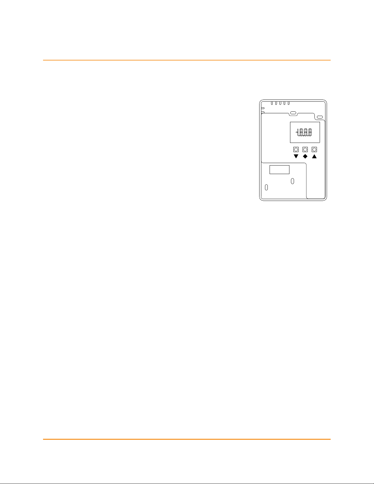
Auto Configuration
IMPORTANT: The device will not activate the BACnet interface until the baud rate and the MS/TP MAC
address are configured. If an active RS485 network is not available, configure the device using the Setup
Menu (documented in the User’s Guide).
Access the auto configuration wizard by removing the front cover and
pressing the ▼, ◆, and ▲ buttons for one second. After the wizard activates,
the display will show
The wizard automatically advances between each step after a few seconds.
Pressing the ◆ button also advances the wizard.
The baud rate value can usually be detected from existing
network activity. If no baud rate could be detected, the display
will show
rate before advancing.
The device detects the smallest free MAC address on the local
MS/TP subnet from existing network activity. If the installation
requires a specific MAC address, use ▼ and ▲ to override the detected address. If the wizard
detects that the selected MAC address conflicts with another device, it automatically advances
to the next smallest free MAC address.
After the wizard completes, the device saves the baud rate and MS/TP MAC address. Additionally, the
device adds 665000 to the selected MAC address and saves the resulting sum as the device object ID. If the
object ID conflicts with another device on the network, use
unique object ID.
The BACnet interface becomes active immediately after the wizard completes. To re-configure the baud
rate and MAC address, use the Setup Menu or run the wizard again.
.
. If necessary, use ▼ and ▲ to change the baud
, , and in the Setup Menu to set a
AQ Series BACnet Protocol Guide Page 5 of 20 154-0012-0E
Page 6

Device
• Object Identifier W
• Object Name W 30 characters maximum
• Object Type R
• System Status R
• Vendor Name R
• Vendor Identifier R
• Model Name R
• Firmware Revision R
• Application Software Version R
• Location W 30 characters maximum
• Description W 30 characters maximum
• Protocol Version R
• Protocol Revision R
• Protocol Services Supported R
• Protocol Object Types Supported R
• Object List R
• Max APDU Length Accepted R
• Segmentation Supported R
• APDU Timeout R
• Number of APDU Retries R
• Max Master W 1 – 127
• Max Info Frames W 1 – 65535
• Device Address Binding R
• Database Revision R
• Serial Number R
• Last Restart Reason R
• Property List R
• Device Features R Proprietary, ID 6650
This read-only property, of type “bit string”, lists the hardware features associated with the device
model. Each ‘1’ in the value represents a feature that is present, and each ‘0’ represents a disabled
feature. BACnet objects corresponding to disabled features should not be accessed.
0. RS485 Protocol
1. Analog Outputs (always disabled)
2. Temperature Sensor
3. Humidity Sensor
4. CO2 Sensor
5. Set Point Slider
6. Push Button
7. Relay Output
8. LCD Screen
9. Internal Thermistor
AQ Series BACnet Protocol Guide Page 6 of 20 154-0012-0E
Page 7

Analog Inputs
• Object Identifier R
• Object Name R
• Object Type R
• Present Value W Only writable when Out Of Service is TRUE
• Status Flags R
• Event State R
• Reliability W Only writable when Out Of Service is TRUE
• Out of Service W
• Update Interval R
• Units of Measure R
• Minimum Present Value R
• Maximum Present Value R
• Resolution R
• Property List R
AI 0 Temperature
Returns the current ambient temperature. This value is an average of ambient temperature
readings (see AI 1). The averaging time is configurable (see AV 7).
AI 1 Temperature (unsmoothed)
Returns the most recent ambient temperature reading. The value is compensated according to
the user calibration (see AV 5 and AV 6). On models with the Humidity Sensor feature, the
humidity sensor module provides ambient temperature readings. On other models, the
internal thermistor provides ambient temperature readings.
AI 2 Minimum Temperature
Returns the lowest ambient temperature recorded since this value was reset. This value is reset
when written, and when the device restarts.
AI 3 Maximum Temperature
Returns the highest ambient temperature recorded since this value was reset. This value is
reset when written, and when the device restarts.
AI 4 Relative Humidity
Returns the current relative humidity. This value is an average of relative humidity readings
(see AI 5). The averaging time is configurable (see AV 10).
This object is only valid in models with the Humidity Sensor feature.
AQ Series BACnet Protocol Guide Page 7 of 20 154-0012-0E
Page 8

AI 5 Relative Humidity (unsmoothed)
Returns the most recent relative humidity reading. The value is compensated according to the
user calibration (see AV 8 and AV 9).
This object is only valid in models with the Humidity Sensor feature.
AI 6 Minimum Relative Humidity
Returns the lowest relative humidity recorded since this value was reset. This value is reset
when written, and when the device restarts.
This object is only valid in models with the Humidity Sensor feature.
AI 7 Maximum Relative Humidity
Returns the highest relative humidity recorded since this value was reset. This value is reset
when written, and when the device restarts.
This object is only valid in models with the Humidity Sensor feature.
AI 8 Dew Point Temperature
Returns the current dew point temperature. This value is an average of dew point temperature
calculations (see AI 9). The averaging time is configurable (see AV 13).
This object is only valid in models with the Humidity Sensor feature.
AI 9 Dew Point Temperature (unsmoothed)
Returns the most recent dew point temperature calculation. The value is compensated
according to the user calibration (see AV 11 and AV 12). Because the calculation takes the
ambient temperature and relative humidity readings as input, the respective user
compensation values (see AV 5, AV 6, AV 8, and AV 9) also affect the calculated result. This
object is only valid in models with the Humidity Sensor feature.
AI 10 Minimum Dew Point Temperature
Returns the lowest dew point temperature recorded since this value was reset. This value is
reset when written, and when the device restarts.
This object is only valid in models with the Humidity Sensor feature.
AI 11 Maximum Dew Point Temperature
Returns the highest dew point temperature recorded since this value was reset. This value is
reset when written, and when the device restarts.
This object is only valid in models with the Humidity Sensor feature.
AI 12 CO2 Concentration
Returns the current CO2 concentration. This value is an average of CO2 concentration readings
(see AI 13). The averaging time is configurable (see AV 16).
This object is only valid in models with the CO2 Sensor feature.
AQ Series BACnet Protocol Guide Page 8 of 20 154-0012-0E
Page 9

AI 13 CO2 Concentration (unsmoothed)
Returns the most recent CO2 concentration reading. The value is compensated according to
the user calibration (see AV 14 and AV 15).
This object is only valid in models with the CO2 Sensor feature.
AI 14 Minimum CO2 Concentration
Returns the lowest CO2 concentration recorded since this value was reset. This value is reset
when written, and when the device restarts.
This object is only valid in models with the CO2 Sensor feature.
AI 15 Maximum CO2 Concentration
Returns the highest CO2 concentration recorded since this value was reset. This value is reset
when written, and when the device restarts.
This object is only valid in models with the CO2 Sensor feature.
AI 16 User Set Point
Returns the current set point value. On models with the Set Point Slider feature, the user
changes the set point by adjusting the slider position. On other models, the user changes the
set point by pressing the ▽ and △ buttons. The range is configurable (see AV 20 and AV 21).
AI 17 Minimum User Set Point
Returns the lowest user set point value recorded since this value was reset. This value is reset
when written, and when the device restarts.
AI 18 Maximum User Set Point
Returns the highest user set point value recorded since this value was reset. This value is reset
when written, and when the device restarts.
AQ Series BACnet Protocol Guide Page 9 of 20 154-0012-0E
Page 10

Analog Values
• Object Identifier R
• Object Name R
• Object Type R
• Present Value W Range varies by object instance
• Status Flags R
• Event State R
• Out of Service R
• Units of Measure R
• Minimum Present Value R
• Maximum Present Value R
• Resolution R
• Property List R
AV 0 MAC Address
Sets the device MS/TP address. The MAC address must be in a valid MS/TP master address,
between 0 and 127. The device will reply to the Write-Property APDU using with the original
MAC address. If the change is successful, all subsequent APDUs must be transmitted to the
new MAC address. For an easy way to initialize the MAC address when the device is first
installed, see Auto Configuration (page 5).
This parameter is equivalent to in the Setup Menu.
Default: Not configured. This parameter is saved in the device configuration.
AV 1 Device Uptime
Returns the time since the last device restart, in seconds. Read only.
AV 2 Device Restart Count
Returns the number of times the device has restarted. Read only.
AV 3 Display Contrast
Sets the contrast of the LCD screen. Larger values make the screen darker. The contrast can be
adjusted between 0% and 100%, and the ideal value depends on ambient lighting conditions
in the installed location.
This parameter is equivalent to in the Setup Menu.
Default: 50%. This parameter is saved in the device configuration.
AV 4 Display Rotate Time
If multiple measurements are selected for display (see MSV 0), sets the number of seconds that
each will be displayed before switching. The display is continuously refreshed during each
measurement’s display interval. If a measurement is selected, but the corresponding sensor
AQ Series BACnet Protocol Guide Page 10 of 20 154-0012-0E
Page 11

option is not installed, that measurement will be skipped in the rotation. If a measurement is
unreliable (e.g. the respective sensor module was removed), the display will show “
This parameter is equivalent to in the Setup Menu.
Default: 10 seconds. This parameter is saved in the device configuration.
AV 5 Temperature Calibration Slope
See AV 6.
Default: 1.0. This parameter is saved in the device configuration
AV 6 Temperature Calibration Offset
Together with the slope (see AV 5), allows user compensation of raw temperature readings.
𝑇
𝑢𝑠𝑒𝑟
This parameter is equivalent to in the Setup Menu.
Default: 0.0 °F (0.0 °C). This parameter is saved in the device configuration.
AV 7 Temperature Response Time
Sets the averaging time of the ambient temperature measurement (see AI 0), in whole seconds.
Averaging is implemented as a first order exponential filter. The response time is defined at
90% step. Setting a response time of 0 seconds disables the filter.
= 𝐴𝑉5∙ 𝑇
𝑟𝑎𝑤
“.
+ 𝐴𝑉6
This parameter is equivalent to in the Setup Menu.
Default: 30 seconds. This parameter is saved in the device configuration.
AV 8 Relative Humidity Calibration Slope
See AV 9.
Default: 1.0. This parameter is saved in the device configuration.
AV 9 Relative Humidity Calibration Offset
Together with the slope (see AV 8), allows user compensation of raw relative humidity readings.
𝑅𝐻
This parameter is equivalent to in the Setup Menu.
Default: 0 %RH. This parameter is saved in the device configuration.
= 𝐴𝑉8∙ 𝑅𝐻
𝑢𝑠𝑒𝑟
AV 10 Relative Humidity Response Time
Sets the averaging time of the relative humidity measurement (see AI 4), in whole seconds.
Averaging is implemented as a first order exponential filter. The response time is defined at
90% step. Setting a response time of 0 seconds disables the filter.
This parameter is equivalent to in the Setup Menu.
Default: 30 seconds. This parameter is saved in the device configuration.
𝑟𝑎𝑤
+ 𝐴𝑉9
AQ Series BACnet Protocol Guide Page 11 of 20 154-0012-0E
Page 12

AV 11 Dew Point Calibration Slope
See AV 12.
Default: 1.0. This parameter is saved in the device configuration.
AV 12 Dew Point Calibration Offset
Together with the slope (see AV 11), allows user compensation of dew point temperature
calculation.
Default: 0.0 °F (0.0 °C). This parameter is saved in the device configuration.
AV 13 Dew Point Response Time
Sets the averaging time of the dew point calculation (see AI 8), in whole seconds. Averaging is
implemented as a first order exponential filter. The response time is defined at 90% step.
Setting a response time of 0 seconds disables the filter.
Default: 30 seconds. This parameter is saved in the device configuration.
AV 14 CO2 Calibration Slope
See AV 15.
Default: 1.0. This parameter is saved in the device configuration.
AV 15 CO2 Calibration Offset
Together with the slope (see AV 14), allows user compensation of raw CO2 concentration
readings. If CO2 auto-calibration is enabled (see AV 17), the auto-calibration algorithm
compensates the raw reading before the user compensation.
𝐶𝑂2
This parameter is equivalent to in the Setup Menu.
Default: 0 PPM. This parameter is saved in the device configuration.
𝐷𝑃
= 𝐴𝑉11∙ 𝐷𝑃
𝑢𝑠𝑒𝑟
= 𝐴𝑉14∙ 𝐶𝑂2
𝑢𝑠𝑒𝑟
𝑟𝑎𝑤
𝑟𝑎𝑤
+ 𝐴𝑉12
+ 𝐴𝑉15
AV 16 CO2 Response Time
Sets the averaging time of the CO2 concentration measurement (see AI 12), in whole seconds.
Averaging is implemented as a first order exponential filter. The response time is defined at
90% step. Setting a response time of 0 seconds disables the filter.
This parameter is equivalent to in the Setup Menu.
Default: 30 seconds. This parameter is saved in the device configuration.
AV 17 CO2 Auto Calibration Period
Sets the CO2 auto calibration period, in whole days.
The maximum period is 60 days. Setting the period to 0 days disables auto calibration.
This parameter is equivalent to in the Setup Menu. See the User Guide for a description of
the auto-calibration algorithm.
Default: 14 days. This parameter is saved in the device configuration.
AQ Series BACnet Protocol Guide Page 12 of 20 154-0012-0E
Page 13

AV 18 CO2 Auto Calibration Target
Sets the CO2 auto-calibration target.
This parameter is equivalent to in the Setup Menu. See the User Guide for a description of
the auto-calibration algorithm.
Default: 400 PPM. This parameter is saved in the device configuration.
AV 19 CO2 Auto Calibration Window
Sets the CO2 auto-calibration window range.
This parameter is equivalent to in the Setup Menu. See the User Guide for a description of
the auto-calibration algorithm.
Default: 200 PPM. This parameter is saved in the device configuration.
AV 20 User Set Point Minimum Value
Controls the minimum set point the user can configure. If the set point is controlled by a slider,
this parameter maps to the bottom of the slider’s travel, even when the Maximum Value (see
AV 21) is smaller. The units of this value are configurable (see MSV 3).
This parameter is equivalent to in the Setup Menu.
Default: 50°F. This parameter is saved in the device configuration.
AV 21 User Set Point Maximum Value
Controls the maximum set point the user can configure. If the set point is controlled by a slider,
this parameter maps to the top of the slider’s travel, even when the Minimum Value (see AV 20)
is larger. The units of this value are configurable (see MSV 3).
This parameter is equivalent to in the Setup Menu.
Default: 95°F. This parameter is saved in the device configuration.
AV 22 User Set Point Increment
Controls the minimum increment of the user set point. When changed by a slider, the set point
value is always rounded to the nearest increment. When changed by the ▽ and △ buttons,
the set point value always increases or decreases by the increment value. For best results, set
the increment value no smaller than 1.0% of the set point range.
This parameter is equivalent to in the Setup Menu.
Default: 1.0°F. This parameter is saved in the device configuration.
AV 23 Internal Relay Program Threshold
When the relay comparison polarity (see MSV 5) is active high, the relay (see BO 0) will activate
when the measured value is greater than the threshold. When the polarity is active low, the
relay will activate when the measured value is lower than the threshold.
This parameter is equivalent to in the Setup Menu.
Default: 800. The units vary with the current selected measurement source (see MSV 4). This
parameter is saved in the device configuration.
AQ Series BACnet Protocol Guide Page 13 of 20 154-0012-0E
Page 14

AV 24 Internal Relay Program Hysteresis
When the relay comparison polarity (see MSV 5) is active high, the turn-off threshold is found
by subtracting the hysteresis from the turn-on threshold. When the relay comparison polarity
is active low, the turn-off threshold is found by adding the hysteresis to the turn-on threshold.
This parameter is equivalent to in the Setup Menu.
Default: 100. The units vary with the current selected measurement source (see MSV 4). This
parameter is saved in the device configuration.
AV 25 Internal Relay Program Priority
Sets the priority of the internal relay comparison. The priority must be set between 6 (the
BACnet Minimum On/Off Priority) and 16 (the Minimum priority). The comparison between the
selected internal relay comparison source (see MSV 4) and the threshold (see AV 24) is output at
this priority. If the comparison source is not set to “Disabled”, the device ignores commands at
this priority.
Default: 14. This parameter is saved in the device configuration.
AV 26 Temperature Override Value
Sets an alternate value for display in place of the ambient temperature sensor reading. Writing
any numeric value automatically sets the override enable (see BV 1) to ACTIVE. Writing NULL
automatically sets the override enable to INACTIVE.
Default: 32.0 °F (0.0 °C). This parameter is reset when the device restarts.
AV 27 Relative Humidity Override Value
Sets an alternate value for display in place of the relative humidity sensor reading. Writing any
numeric value automatically sets the override enable (see BV 2) to ACTIVE. Writing NULL
automatically sets the override enable to INACTIVE.
This parameter is only applicable to models with the Humidity Sensor.
Default: 0 %RH. This parameter is reset when the device restarts.
AV 28 Dew Point Temperature Override Value
Sets an alternate value for display in place of the dew point temperature calculation. Writing
any numeric value automatically sets the override enable (see BV 3) to ACTIVE. Writing NULL
automatically sets the override enable to INACTIVE.
This parameter is only applicable to models with the Humidity Sensor.
Default: 32.0 °F (0.0 °C). This parameter is reset when the device restarts.
AV 29 CO2 Concentration Override Value
Sets an alternate value for display in place of the CO2 concentration sensor reading. Writing
any numeric value automatically sets the override enable (see BV 4) to ACTIVE. Writing NULL
automatically sets the override enable to INACTIVE.
This parameter is only applicable to models with the CO2 Sensor.
Default: 0 PPM. This parameter is reset when the device restarts.
AQ Series BACnet Protocol Guide Page 14 of 20 154-0012-0E
Page 15

Binary Inputs
• Object Identifier R
• Object Name R
• Object Type R
• Present Value W Only writable when Out Of Service is TRUE
• Status Flags R
• Event State R
• Reliability W Only writable when Out Of Service is TRUE
• Out of Service W
• Polarity R
• Inactive Text R
• Active Text R
• Change of State Count W Any write resets the count to ‘0’
• Elapsed Active Time R
• Property List R
BI 0 User Push Button
Returns the state of the user push button, if installed. For effect, the button must be read by an
external controller. It does not affect any states or processes within the device.
AQ Series BACnet Protocol Guide Page 15 of 20 154-0012-0E
Page 16

Binary Outputs
• Object Identifier R
• Object Name R
• Object Type R
• Present Value W
• Status Flags R
• Event State R
• Reliability W
• Out of Service W
• Polarity R
• Inactive Text R
• Active Text R
• Change of State Count W Any write resets the count to ‘0’
• Elapsed Active Time R
• Minimum Off Time W 0 – 65536 seconds
• Minimum On Time W 0 – 65536 seconds
• Priority Array R
• Relinquish Default W
• Property List R
BO 0 Relay Output
Sets the state of the relay. This object implements the BACnet binary output command
prioritization algorithm.
An internal comparison result may be output at a configurable command priority (see AV 25).
The command output at the configured priority is continuously calculated by comparing a
specified measurement (see MSV 4) with a fixed threshold value (see AV 23). If the specified
measurement is invalid (or set to “Disabled”), and all priorities are relinquished by writing NULL,
the Relinquish Default value is output.
AQ Series BACnet Protocol Guide Page 16 of 20 154-0012-0E
Page 17

Binary Values
• Object Identifier R
• Object Name R
• Object Type R
• Present Value W
• Status Flags R
• Event State R
• Out of Service R
• Inactive Text R
• Active Text R
• Property List R
BV 0 Identify Device
Displays the device MAC address instead of the normal measurement rotation. The MAC
address display overrides the normal display for long as this value remains ACTIVE.
Default: INACTIVE. This parameter is reset when the device restarts
BV 1 Temperature Override Enable
Selects the value source when the ambient temperature is displayed. When ACTIVE, selects the
override value (AV 26). When INACTIVE, selects the smoothed sensor reading (AI 0).
Default: INACTIVE. This parameter is reset when the device restarts.
BV 2 Relative Humidity Override Enable
Selects the value source when the relative humidity is displayed. When ACTIVE, selects the
override value (AV 27). When INACTIVE, selects the smoothed sensor reading (AI 4).
This object is only present in models with the Humidity Sensor feature.
Default: INACTIVE. This parameter is reset when the device restarts.
BV 3 Dew Point Temperature Override Enable
Selects the value source when the dew point temperature is displayed. When ACTIVE, selects
the override value (AV 28). When INACTIVE, selects the smoothed sensor reading (AI 8).
This object is only present in models with the Humidity Sensor feature.
Default: INACTIVE. This parameter is reset when the device restarts.
BV 4 CO2 Concentration Override Enable
Selects the value source when the CO2 concentration is displayed. When ACTIVE, selects the
override value (AV 29). When INACTIVE, selects the smoothed sensor reading (AI 12).
This object is only present in models with the CO2 Sensor feature.
Default: INACTIVE. This parameter is reset when the device restarts.
AQ Series BACnet Protocol Guide Page 17 of 20 154-0012-0E
Page 18

Multi State Values
• Object Identifier R
• Object Name R
• Object Type R
• Present Value W
• Status Flags R
• Event State R
• Out of Service R
• Number of States R
• State Text R
• Property List R
MSV 0 Display Selection
Selects the set of measurements for display. If more than one measurement is selected, each
measurement displays in rotation. The Display Rotate Time (see AV 4) controls how long each
measurement is displayed before switching.
Possible values:
1. Display Off
2. User Selection
3. Temperature Only
4. Relative Humidity Only
5. Temperature and Relative Humidity
6. CO2 Only
7. Temperature And CO2
8. Relative Humidity and CO2
9. Temperature, Relative Humidity, and CO2
10. Dew Point Only
11. Set Point Only
When the value is “User Selection”, the user can change the set of selected measurements with
in the User Menu (see the User’s Guide). Any other value overrides the user’s selection.
This parameter is equivalent to in the Setup Menu.
Default: User Selection. This parameter is saved in the device configuration.
MSV 1 Display Temperature Units
Defines the units when the device displays ambient temperature or dew point temperature.
Also controls the units when editing parameters using the LCD menu system.
Possible values:
1. User Selection
2. Degrees Fahrenheit
3. Degrees Celsius
AQ Series BACnet Protocol Guide Page 18 of 20 154-0012-0E
Page 19

This parameter does not affect the unit system of temperature values read or written through
BACnet (see MSV 2).
When the value is “User Selection”, the user can change the temperature display units with
in the User Menu (see the User’s Guide). Any other value overrides the user’s selection.
This parameter is equivalent to in the Setup Menu.
Default: User Selection. This parameter is saved in the device configuration.
MSV 2 BACnet Temperature Units
Controls the units used for reading and writing ambient temperature and dew point
temperature values through BACnet objects. The selection can be verified by reading the
“Units of Measure” property of any affected object (e.g. AI 0, Temperature).
Possible values:
1. Degrees Fahrenheit
2. Degrees Celsius
This parameter does not affect the units of temperatures displayed on the device (see MSV 1).
This parameter can only be set through BACnet.
Default: Degrees Fahrenheit. This parameter is saved in the device configuration.
MSV 3 User Set Point Units
Controls the units when the device displays the current set point value. Because set point
values are interpreted by the external control system, the device uses the selected units for
display only.
Possible values:
1. Disabled
2. No Units (value only)
3. Degrees Fahrenheit
4. Degrees Celsius
5. Relative Humidity (%RH)
6. Parts Per Million (ppm)
7. Pounds per Square Inch (psi)
8. Kilopascals (kPa)
9. Inches of Water Column (“WC)
This parameter is equivalent to in the Setup Menu.
Default: Degrees Fahrenheit. This parameter is saved in the device configuration.
MSV 4 Internal Relay Program Source
Selects a measurement source for the internal relay threshold comparison (see BO 0).
Possible values:
1. Disabled
2. Temperature
3. Temperature (unsmoothed)
4. Relative Humidity
5. Relative Humidity (unsmoothed)
6. Dew Point Temperature
7. Dew Point Temperature (unsmoothed)
AQ Series BACnet Protocol Guide Page 19 of 20 154-0012-0E
Page 20

8. CO2 Concentration
9. CO2 Concentration (unsmoothed)
10. User Set Point
If the selected measurement source is invalid, the internal relay comparison will be disabled.
NULL will be written to the corresponding entry in the commandable priority array.
This parameter is equivalent to in the Setup Menu, with additional options.
Default: CO2 Concentration. This parameter is saved in the device configuration.
MSV 5 Internal Relay Program Polarity
Sets the polarity of the internal relay threshold comparison.
1. Active High
2. Active Low
When the polarity is active high, the relay (see BO 0) will activate when the selected
measurement is greater than the threshold value (see AV 23). When the polarity is active low,
the relay will activate when the measured value is lower than the threshold value.
This parameter is equivalent to in the Setup Menu.
Default: Active High. This parameter is saved in the device configuration.
AQ Series BACnet Protocol Guide Page 20 of 20 154-0012-0E
 Loading...