

Page 1

SENTRON
Power Monitoring Device
SENTRON PAC4200
System Manual
Introduction
Safety instructions
Description
Operation planning
Installation
Connecting
Startup
Operator control
Parameterizing
Service and maintenance
Technical data
Dimension drawings
Appendix
ESD guidelines
List of abbreviations
1
2
3
4
5
6
7
8
9
10
11
12
A
B
C
09/2009
A5E02316180B-02
Page 2
Legal information
Warning notice system
This manual contains notices you have to observe in order to ensure your personal safety, as well as to prevent
damage to property. The notices referring to your personal safety are highlighted in the manual by a safety alert
symbol, notices referring only to property damage have no safety alert symbol. These notices shown below are
graded according to the degree of danger.
DANGER
indicates that death or severe personal injury will result if proper precautions are not taken.
WARNING
indicates that death or severe personal injury may result if proper precautions are not taken.
CAUTION
with a safety alert symbol, indicates that minor personal injury can result if proper precautions are not taken.
CAUTION
without a safety alert symbol, indicates that property damage can result if proper precautions are not taken.
NOTICE
indicates that an unintended result or situation can occur if the corresponding information is not taken into
account.
If more than one degree of danger is present, the warning notice representing the highest degree of danger will
be used. A notice warning of injury to persons with a safety alert symbol may also include a warning relating to
property damage.
Qualified Personnel
The product/system described in this documentation may be operated only by personnel qualified for the specific
task in accordance with the relevant documentation for the specific task, in particular its warning notices and
safety instructions. Qualified personnel are those who, based on their training and experience, are capable of
identifying risks and avoiding potential hazards when working with these products/systems.
Proper use of Siemens products
Note the following:
WARNING
Siemens products may only be used for the applications described in the catalog and in the relevant technical
documentation. If products and components from other manufacturers are used, these must be recommended
or approved by Siemens. Proper transport, storage, installation, assembly, commissioning, operation and
maintenance are required to ensure that the products operate safely and without any problems. The permissible
ambient conditions must be adhered to. The information in the relevant documentation must be observed.
Trademarks
All names identified by ® are registered trademarks of the Siemens AG. The remaining trademarks in this
publication may be trademarks whose use by third parties for their own purposes could violate the rights of the
owner.
Disclaimer of Liability
We have reviewed the contents of this publication to ensure consistency with the hardware and software
described. Since variance cannot be precluded entirely, we cannot guarantee full consistency. However, the
information in this publication is reviewed regularly and any necessary corrections are included in subsequent
editions.
Siemens AG
Industry Sector
Postfach 48 48
90026 NÜRNBERG
GERMANY
Ordernumber: 3ZX1012-0KM42-3AC0
Ⓟ 10/2009
Copyright © Siemens AG 2008,
2009.
Technical data subject to change
Page 3

Table of contents
1 Introduction.............................................................................................................................................. 13
1.1 Purpose of this document ............................................................................................................13
1.2 Orientation aids............................................................................................................................13
1.3 Components of the product..........................................................................................................14
1.4 Contents of the data carrier .........................................................................................................14
1.5 Latest information and correction sheet.......................................................................................14
1.6 Further documentation.................................................................................................................15
2 Safety instructions ................................................................................................................................... 17
2.1 Safety notes .................................................................................................................................17
3 Description............................................................................................................................................... 19
3.1 Performance features of the SENTRON PAC4200 .....................................................................19
3.2 Measuring inputs..........................................................................................................................24
3.3 Measured variables......................................................................................................................25
3.3.1 Sliding window demand values....................................................................................................31
3.3.2 Other properties of measured variable representation ................................................................32
3.4 Load profile ..................................................................................................................................33
3.4.1 Overview ......................................................................................................................................33
3.4.2 Historical load profile....................................................................................................................36
3.4.3 Current load profile data at the communication interfaces ..........................................................37
3.4.4 Synchronization of the load profile...............................................................................................37
3.4.5 Additional information about the load profile data........................................................................39
3.5 Tariffs ...........................................................................................................................................39
3.6 Technical features of the supply quality.......................................................................................40
3.7 Date and time...............................................................................................................................43
3.8 Limits............................................................................................................................................44
3.9 Function of the digital inputs and outputs ....................................................................................46
3.10 Ethernet port ................................................................................................................................48
3.11 Slots for expansion modules........................................................................................................49
3.12 Gateway .......................................................................................................................................50
3.13 Slots .............................................................................................................................................52
3.14 Password protection ....................................................................................................................54
3.15 User-definable displays................................................................................................................54
3.16 Events ..........................................................................................................................................55
SENTRON PAC4200
System Manual, 09/2009, A5E02316180B-02
3
Page 4

Table of contents
3.17 Performance features of the PAC PROFIBUS DP expansion module ....................................... 60
3.18 Performance features of the PAC RS485 expansion module..................................................... 61
3.19 Performance features of the SENTRON PAC 4DI/2DO expansion module............................... 61
4 Operation planning .................................................................................................................................. 63
4.1 Operation planning...................................................................................................................... 63
5 Installation ............................................................................................................................................... 67
5.1 Unpacking ................................................................................................................................... 67
5.2 Insert battery ............................................................................................................................... 68
5.3 Tools............................................................................................................................................ 69
5.4 Mounting on the switching panel................................................................................................. 70
5.4.1 Mounting dimensions .................................................................................................................. 70
5.4.2 Installation steps ......................................................................................................................... 70
5.5 Installing the expansion modules................................................................................................ 74
5.6 Deinstalling.................................................................................................................................. 76
5.7 Disassembling an expansion module ......................................................................................... 77
6 Connecting .............................................................................................................................................. 79
6.1 Safety notes ................................................................................................................................ 79
6.2 Connections ................................................................................................................................ 80
6.3 Connecting the cables to the terminals....................................................................................... 86
6.4 Connection examples.................................................................................................................. 87
6.5 Grounding of the Ethernet cable ................................................................................................. 94
6.6 Connecting the PAC RS485 expansion module ......................................................................... 96
6.7 Connecting the SENTRON PAC 4DI/2DO expansion module ................................................... 98
7 Startup................................................................................................................................................... 101
7.1 Overview ................................................................................................................................... 101
7.2 Applying the supply voltage ...................................................................................................... 101
7.3 Parameterizing the device......................................................................................................... 103
7.3.1 Procedure.................................................................................................................................. 103
7.3.2 Language .................................................................................................................................. 103
7.3.3 Date and time............................................................................................................................ 105
7.3.4 Voltage input ............................................................................................................................. 106
7.3.4.1 Set the connection type............................................................................................................. 106
7.3.4.2 Measurement using voltage transducers.................................................................................. 107
7.3.4.3 Setting the conversion ratio of the voltage transducer.............................................................. 108
7.3.4.4 Setting the voltage input............................................................................................................ 109
7.3.5 Current input ............................................................................................................................. 110
7.3.5.1 Setting the conversion ratio of the current transducer .............................................................. 110
7.4 Applying the measuring voltage................................................................................................ 111
7.5 Applying the measuring current ................................................................................................ 111
7.6 Check the displayed measured values ..................................................................................... 112
SENTRON PAC4200
4 System Manual, 09/2009, A5E02316180B-02
Page 5

Table of contents
8 Operator control..................................................................................................................................... 113
8.1 Device interface .........................................................................................................................113
8.1.1 Displays and operator controls ..................................................................................................113
8.1.2 Display of the measured variables.............................................................................................120
8.1.3 Display of the "MAIN MENU".....................................................................................................123
8.1.4 Display of the "SETTINGS" menu..............................................................................................124
8.1.5 Display of the device settings ....................................................................................................126
8.1.6 Edit mode of the device settings................................................................................................127
8.2 Operator input steps ..................................................................................................................128
8.2.1 Operator input steps in the measured variable display .............................................................128
8.2.2 Operator input steps in the "MAIN MENU" ................................................................................130
8.2.3 Operator input steps in the "SETTINGS" menu.........................................................................131
8.2.4 Operator input steps in device settings display .........................................................................131
8.2.5 Operator input steps in edit mode of the device settings...........................................................132
8.3 Special displays .........................................................................................................................133
8.3.1 Phasor diagram..........................................................................................................................133
9 Parameterizing ...................................................................................................................................... 135
9.1 Introduction ................................................................................................................................135
9.2 Parameterizing the operator interface .......................................................................................135
9.2.1 Groups of settings......................................................................................................................135
9.2.2 Device information .....................................................................................................................136
9.2.3 Language and regional settings.................................................................................................137
9.2.4 Basic parameters .......................................................................................................................137
9.2.5 Power demand...........................................................................................................................141
9.2.6 Date / time..................................................................................................................................142
9.2.7 Integrated I/Os ...........................................................................................................................144
9.2.8 Communication ..........................................................................................................................149
9.2.9 Display .......................................................................................................................................150
9.2.10 Advanced ...................................................................................................................................151
9.2.11 Password management .............................................................................................................159
9.2.11.1 Calling password management..................................................................................................159
9.2.11.2 Switch on password protection ..................................................................................................160
9.2.11.3 Switch off password protection ..................................................................................................161
9.2.11.4 Change password ......................................................................................................................161
9.2.11.5 Password lost - what to do?.......................................................................................................162
9.2.12 Expansion modules....................................................................................................................163
9.2.13 Configuring the PAC RS485 expansion module........................................................................163
9.2.14 Configuring the SENTRON PAC 4DI/2DO expansion module ..................................................165
9.3 Diagnostics LED of the SENTRON PAC 4DI/2DO expansion module......................................167
10 Service and maintenance ...................................................................................................................... 169
10.1 Calibration ..................................................................................................................................169
10.2 Cleaning .....................................................................................................................................169
10.3 Firmware updates ......................................................................................................................169
10.4 Replacing the battery .................................................................................................................170
10.5 Repair.........................................................................................................................................173
10.6 Disposal .....................................................................................................................................173
SENTRON PAC4200
System Manual, 09/2009, A5E02316180B-02
5
Page 6

Table of contents
11 Technical data ....................................................................................................................................... 175
11.1 Technical data........................................................................................................................... 175
11.2 Cable ......................................................................................................................................... 184
11.3 PAC RS485 expansion module - standards ............................................................................. 184
11.4 Technical data for the PAC RS485 expansion module............................................................. 185
11.5 Communications interface of the PAC RS485 expansion module............................................ 186
11.6 Technical data of the SENTRON PAC 4DI/2DO expansion module ........................................ 188
11.7 Labeling..................................................................................................................................... 190
11.8 Labeling on the PAC RS485 expansion module....................................................................... 191
11.9 Labeling on the SENTRON PAC 4DI/2DO expansion module ................................................. 192
12 Dimension drawings .............................................................................................................................. 193
12.1 Dimension drawings of the PAC RS485 expansion module..................................................... 196
12.2 Dimension drawings of the SENTRON PAC 4DI/2DO expansion module ............................... 197
A Appendix................................................................................................................................................ 199
A.1 Measured variables................................................................................................................... 199
A.2 Load profile ............................................................................................................................... 225
A.3 MODBUS................................................................................................................................... 225
A.3.1 Measured variables without a time stamp with the function codes 0x03 and 0x04.................. 225
A.3.2 Structure - Digital inputs status and digital outputs status with the function codes 0x01
and 0x02....................................................................................................................................
233
A.3.3 Structure - Limit values with the function codes 0x01 and 0x02............................................... 234
A.3.4 Structure - PMD diagnostics and status with the function codes 0x03 and 0x04..................... 234
A.3.5 Measured variables for the load profile with the function codes 0x03 and 0x04 ...................... 235
A.3.6 Tariff-specific energy values in double format with the function codes 0x03, 0x04, and
0x10...........................................................................................................................................
237
A.3.7 Tariff-specific energy values in float format with the function codes 0x03 and 0x04................ 238
A.3.8 Maximum values with a time stamp and the function codes 0x03 and 0x04............................ 239
A.3.9 Minimum values with a time stamp and the function codes 0x03 and 0x04............................. 242
A.3.10 Harmonics without a time stamp with the function codes 0x03 and 0x04 ................................ 245
A.3.11 Harmonics with a time stamp and the function codes 0x03 and 0x04...................................... 249
A.3.12 Configuration settings with the function codes 0x03, 0x04, and 0x10...................................... 254
A.3.13 Value range for limit source ...................................................................................................... 260
A.3.14 Communication settings with the function codes 0x03, 0x04, and 0x10 .................................. 266
A.3.15 I&M settings .............................................................................................................................. 268
A.3.16 Commands with the function code 0x06 ................................................................................... 269
A.3.17 MODBUS standard device identification with the function code 0x2B ..................................... 270
A.4 Correction sheet........................................................................................................................ 271
B ESD guidelines ...................................................................................................................................... 273
B.1 Electrostatic sensitive devices (ESD) ....................................................................................... 273
C List of abbreviations............................................................................................................................... 275
C.1 Abbreviations ............................................................................................................................ 275
Glossary ................................................................................................................................................ 277
Index...................................................................................................................................................... 279
SENTRON PAC4200
6 System Manual, 09/2009, A5E02316180B-02
Page 7

Table of contents
Tables
Table 3- 1 Available connection types ..........................................................................................................25
Table 3- 2 Display of the measured variables depending on the connection type .......................................28
Table 3- 3 Historical load profile....................................................................................................................36
Table 3- 4 Meaning of the symbols in the events list....................................................................................56
Table 3- 5 The following events are reported: ..............................................................................................57
Table 7- 1 Connection of supply voltage.....................................................................................................102
Table 7- 2 Available connection types ........................................................................................................106
Table 8- 1 Assignments of the function keys in the "MAIN MENU" ............................................................124
Table 8- 2 Assignments of the function keys in the "SETTINGS" menu.....................................................125
Table 8- 3 Assignments of the function keys in the device settings display ...............................................126
Table 8- 4 Assignments of the function keys in edit mode of the device settings.......................................128
Table 8- 5 Symbols used in the phasor diagram ........................................................................................133
Table 8- 6 Values in the phasor diagram ....................................................................................................134
Table 9- 1 Setting options in the field "TARGET" depending on the action selected .................................149
Table 9- 2 Structure of the setting versions ................................................................................................164
Table 9- 3 Setting options ...........................................................................................................................165
Table 9- 4 Performance calculation ............................................................................................................165
Table 9- 5 Status in the "DIAG" field with meaning.....................................................................................166
Table 9- 6 Status and fault indication by the LED.......................................................................................167
Table 11- 1 The device meets the following standards.................................................................................184
Table 11- 2 Mechanical data for the PAC RS485 expansion module...........................................................185
Table 11- 3 Electrical data for the PAC RS485 expansion module ..............................................................185
Table 11- 4 Ambient and environmental conditions......................................................................................186
Table 11- 5 Technical data for the communication interface ........................................................................186
Table 11- 6 Connection types with associated conductor cross-sections ....................................................187
Table 11- 7 Technical data of the terminal block ..........................................................................................187
Table 11- 8 Mechanical data of the SENTRON PAC 4DI/2DO expansion module ......................................188
Table 11- 9 Electrical data of the SENTRON PAC 4DI/2DO expansion module..........................................188
Table 11- 10 Technical data of the digital inputs ............................................................................................189
Table 11- 11 Technical data of the digital outputs ..........................................................................................189
Table A- 1 Measured variables available without a time stamp ..................................................................226
Table A- 2 Meaning of the abbreviations in the "Access" column...............................................................232
Table A- 3 Structure - Digital Inputs Status and Digital Outputs Status......................................................233
Table A- 4 Structure - Digital inputs status and digital outputs status for an expansion module
SENTRON PAC 4DI/2DO on slot 1 ...........................................................................................
SENTRON PAC4200
System Manual, 09/2009, A5E02316180B-02
233
7
Page 8

Table of contents
Table A- 5 Structure - Digital inputs status and digital outputs status for an expansion module
SENTRON PAC 4DI/2DO on slot 2 ..........................................................................................
Table A- 6 Modbus Offset 203, Register 2: Limit Violations....................................................................... 234
Table A- 7 Overview of status and diagnostics bytes................................................................................. 234
Table A- 8 Modbus offset 205, tab 2: Structure of PMD diagnostics and status........................................ 235
Table A- 9 Measured variables available with a time stamp ...................................................................... 235
Table A- 10 Meaning of the abbreviations in the "Access" column.............................................................. 237
Table A- 11 Available tariff-specific measured variables.............................................................................. 237
Table A- 12 Meaning of the abbreviations in the "Access" column.............................................................. 238
Table A- 13 Available tariff-specific measured variables.............................................................................. 238
Table A- 14 Meaning of the abbreviations in the "Access" column.............................................................. 238
Table A- 15 Available measured variables: Maximum values with time stamp............................................ 239
Table A- 16 Available measured variables: Minimum values with time stamp............................................. 242
Table A- 17 Harmonics of the voltage .......................................................................................................... 245
Table A- 18 Harmonics of the current........................................................................................................... 247
233
Table A- 19 Harmonics of the phase-to-phase voltage ................................................................................ 248
Table A- 20 Harmonics of the voltage .......................................................................................................... 249
Table A- 21 Harmonics of the current........................................................................................................... 251
Table A- 22 Configuration settings ............................................................................................................... 254
Table A- 23 Assignment of the values 0 to 241............................................................................................ 260
Table A- 24 Communication settings............................................................................................................ 266
Table A- 25 Settings for the I&M data........................................................................................................... 268
Table A- 26 Commands................................................................................................................................ 269
Table A- 27 MODBUS standard device identification parameters ............................................................... 270
Table A- 28 Errors, comments, and suggestions for improvements ............................................................ 272
Table C- 1 Meaning of abbreviations.......................................................................................................... 275
Figures
Figure 2-1 Safety-related symbols on the device ......................................................................................... 17
Figure 3-1 Sliding window demand .............................................................................................................. 31
Figure 3-2 Maximum sliding window demand of the active power............................................................... 32
Figure 3-3 Load profile, fixed block method ................................................................................................. 34
Figure 3-4 Load profile, rolling block method ............................................................................................... 34
Figure 3-5 Instantaneous and maximum values of the harmonics of the ph-ph voltage referred to the
fundamental ................................................................................................................................
Figure 3-6 Graph of the phasor diagram ...................................................................................................... 41
SENTRON PAC4200
8 System Manual, 09/2009, A5E02316180B-02
40
Page 9

Table of contents
Figure 3-7 Minimum value of the displacement angle φ with time stamp .....................................................41
Figure 3-8 Value table for the phasor diagram..............................................................................................42
Figure 3-9 Maximum value of the displacement power factor cos φ with time stamp ..................................42
Figure 3-10 Phasor diagram, value table ........................................................................................................43
Figure 3-11 Voltage and current unbalance....................................................................................................43
Figure 3-12 LIMIT LOGIC................................................................................................................................45
Figure 3-13 Representation of limit violations .................................................................................................45
Figure 3-14 Digital output ................................................................................................................................46
Figure 3-15 Types of count signal ...................................................................................................................46
Figure 3-16 Pulse length and turn-off time ......................................................................................................47
Figure 3-17 SENTRON PAC4200, rear...........................................................................................................50
Figure 3-18 SENTRON PAC4200 as a gateway.............................................................................................51
Figure 3-19 Insertion openings of the SENTRON PAC4200 ..........................................................................53
Figure 3-20 Example of a definable display (digital display) ...........................................................................55
Figure 3-21 Example of a freely definable display (bar diagram)....................................................................55
Figure 4-1 Mounting position .........................................................................................................................63
Figure 5-1 Using the battery ..........................................................................................................................69
Figure 5-2 Installation step A, device with screw terminals...........................................................................71
Figure 5-3 Installation step A, device with ring lug terminals ........................................................................72
Figure 5-4 Installation step E, strain relief for RJ45 connector .....................................................................73
Figure 5-5 Schematic view of assembling the expansion module ................................................................75
Figure 5-6 Deinstallation, releasing the locking hooks..................................................................................77
Figure 6-1 Connection designations of the device with screw terminals, rear view......................................80
Figure 6-2 Connection designations of the device with ring lug terminals, rear view ...................................80
Figure 6-3 Connection designations of the device, top view.........................................................................81
Figure 6-4 Terminal labeling, device with screw terminals............................................................................82
Figure 6-5 Terminal designation, device with ring lug terminals ...................................................................83
Figure 6-6 Terminal block: digital input and output, reference potential .......................................................84
Figure 6-7 Connecting cables to the screw terminal .....................................................................................86
Figure 6-8 Connecting the cables to the ring lug terminals:..........................................................................87
Figure 6-9 Connection type 3P4W, without voltage transformer, with three current transformers ...............88
Figure 6-10 Connection type 3P4W, with voltage transformer, with three current transformers ....................88
Figure 6-11 Connection type 3P4WB, without voltage transformer, with one current transformer.................89
Figure 6-12 Connection type 3P4WB, with voltage transformer, with one current transformer......................89
Figure 6-13 Connection type 3P3W, without voltage transformer, with three current transformers ...............90
Figure 6-14 Connection type 3P3W, with voltage transformer, with three current transformers ....................90
SENTRON PAC4200
System Manual, 09/2009, A5E02316180B-02
9
Page 10

Table of contents
Figure 6-15 Connection type 3P3W, without voltage transformer, with two current transformers ................. 91
Figure 6-16 Connection type 3P3W, with voltage transformer, with two current transformers ...................... 91
Figure 6-17 Connection type 3P3WB, without voltage transformer, with one current transformer ................ 92
Figure 6-18 Connection type 3P3WB, with voltage transformer, with one current transformer ..................... 92
Figure 6-19 Connection type 3P4W, without voltage transformer, with two current transformers ................. 93
Figure 6-20 Connection type 1P2W, without voltage transformer, with one current transformer .................. 93
Figure 6-21 Connection type 3P3W, with voltage transformer, with three current transformers ................... 94
Figure 6-22 Grounding of the Ethernet cable ................................................................................................. 95
Figure 6-23 Block diagram: General topology of the twisted-pair cable......................................................... 96
Figure 6-24 Terminal assignment................................................................................................................... 96
Figure 6-25 Terminal assignment with terminating resistor............................................................................ 97
Figure 6-26 Terminal assignment with line polarization ................................................................................. 97
Figure 6-27 Terminal assignment with switching of the digital inputs with internal power supply.................. 98
Figure 6-28 Terminal assignment with switching of the digital inputs with external power supply................. 99
Figure 6-29 Terminal assignment with switching of the digital outputs .......................................................... 99
Figure 7-1 Language selection ................................................................................................................... 104
Figure 7-2 "LANGUAGE" edit mode........................................................................................................... 104
Figure 7-3 "DATE/TIME" device settings.................................................................................................... 105
Figure 7-4 "CONNECTION TYPE" device setting ...................................................................................... 106
Figure 7-5 "USE PTs?" device settings...................................................................................................... 107
Figure 7-6 Device setting "USE PTs?" ....................................................................................................... 108
Figure 7-7 "VOLTAGE INPUTS" device setting ......................................................................................... 109
Figure 7-8 "CURRENT INPUTS" device setting......................................................................................... 110
Figure 8-1 User interface of SENTRON PAC4200..................................................................................... 113
Figure 8-2 Information structure and navigation......................................................................................... 116
Figure 8-3 Scroll bar of the menu list.......................................................................................................... 117
Figure 8-4 Start of the list/end of the list..................................................................................................... 118
Figure 8-5 Scroll bar ................................................................................................................................... 118
Figure 8-6 Symbols for displaying maximum and minimum values ........................................................... 119
Figure 8-7 Symbol for sliding window demand........................................................................................... 119
Figure 8-8 Displaying measured variables ................................................................................................. 120
Figure 8-9 "MAIN MENU" display ............................................................................................................... 123
Figure 8-10 "SETTINGS" display ................................................................................................................. 125
Figure 8-11 Display of the device settings ................................................................................................... 126
Figure 8-12 Edit mode of the device settings ............................................................................................... 127
Figure 8-13 Calling edit mode ...................................................................................................................... 131
SENTRON PAC4200
10 System Manual, 09/2009, A5E02316180B-02
Page 11

Table of contents
Figure 8-14 Phasor diagram..........................................................................................................................133
Figure 8-15 Phasor diagram, instantaneous values......................................................................................134
Figure 9-1 "LANGUAGE SETTING" device setting.....................................................................................137
Figure 9-2 "BASIC PARAMETERS" device setting.....................................................................................137
Figure 9-3 "USE PTs?" device settings.......................................................................................................138
Figure 9-4 "CURRENT INPUTS" device setting..........................................................................................140
Figure 9-5 Minimum current ........................................................................................................................141
Figure 9-6 "DATE/TIME" device settings ....................................................................................................142
Figure 9-7 State I/O module ........................................................................................................................144
Figure 9-8 "DIGITAL OUTPUT" device settings..........................................................................................144
Figure 9-9 "DIGITAL INPUT" device settings..............................................................................................147
Figure 9-10 "COMMUNICATION" device setting ..........................................................................................149
Figure 9-11 "DISPLAY" device setting ..........................................................................................................150
Figure 9-12 "PASSWORD PROTECTION" device settings..........................................................................152
Figure 9-13 Representation of limit violations ...............................................................................................152
Figure 9-14 Effect of delay and hysteresis on upper and lower limit violations ............................................154
Figure 9-15 "LIMIT LOGIC" device settings ..................................................................................................155
Figure 9-16 Data backup in the "CHANGE BATTERY" dialog box...............................................................157
Figure 9-17 "PASSWORD PROTECTION" device setting............................................................................160
Figure 9-18 Configuring the PAC RS485 expansion module using buttons .................................................164
Figure 9-19 Configuring the SENTRON PAC 4DI/2DO expansion module using keys................................166
Figure 10-1 "CHANGE BATTERY" ...............................................................................................................171
Figure 10-2 Indication of completed data backup .........................................................................................171
Figure 10-3 Battery change ...........................................................................................................................172
Figure 11-1 Device labeling...........................................................................................................................190
Figure 11-2 PAC RS485 expansion module with type plate .........................................................................191
Figure 11-3 SENTRON PAC 4DI/2DO expansion module with type plate ...................................................192
Figure 12-1 Panel cutout ...............................................................................................................................193
Figure 12-2 Frame dimensions with optional PAC PROFIBUS DP expansion module connected,
device with screw terminals .......................................................................................................
194
Figure 12-3 Frame dimensions with optional PAC PROFIBUS DP expansion module connected,
device with ring lug terminals.....................................................................................................
194
Figure 12-4 Side-by-side installation .............................................................................................................195
Figure 12-5 Clearances, device with screw terminal (on the left), device with ring lug terminal (on the
right)...........................................................................................................................................
195
Figure 12-6 View from above with the dimensions of the plug connector between the PAC RS485
expansion module and the SENTRON PAC, side view, front view and view from below
with terminal block .....................................................................................................................
SENTRON PAC4200
System Manual, 09/2009, A5E02316180B-02
196
11
Page 12

Table of contents
Figure 12-7 View from above with the dimensions of the plug connector between the
SENTRON PAC 4DI/2DO expansion module and the SENTRON PAC, side view, front
view and view from below with terminal block ..........................................................................
197
SENTRON PAC4200
12 System Manual, 09/2009, A5E02316180B-02
Page 13

Introduction
1.1 Purpose of this document
This present manual describes the SENTRON PAC4200 Power Monitoring Device.
It is intended for the use of:
● Planners
● Plant operators
● Commissioning engineers
● Service and maintenance personnel
Required basic knowledge
A general knowledge of the field of electrical engineering is required to understand this
manual.
Knowledge of the relevant safety regulations and standards is required for installing and
connecting the device.
1
Validity range
This manual applies to the following delivery versions of the device:
SENTRON PAC4200 for panel mounting with
● LC display
● Screw terminal
● Ring lug terminal
● Wide-voltage power supply
The manual describes those device properties valid at the time of its publication.
1.2 Orientation aids
General information
The manual includes the following orientation aids:
● Table of contents
● List of figures and tables
● List of abbreviations
● Glossary
● Index
SENTRON PAC4200
System Manual, 09/2009, A5E02316180B-02
13
Page 14

Introduction
1.3 Components of the product
1.3 Components of the product
Description
The package includes:
● 1 SENTRON PAC4200 Power Monitoring Device
● 1 battery
● 2 brackets for panel mounting
● 1 SENTRON PAC4200 operating instructions
● 1 data carrier (CD-ROM or DVD)
1.4 Contents of the data carrier
Contents of the data carrier
A data carrier (CD or DVD) is supplied with the SENTRON PAC4200 Power Monitoring
Device. You will find the following files on the data carrier:
● Manual and operating instructions for SENTRON PAC4200 in all available languages
● Manuals and operating instructions for optional expansion modules in all available
languages
● All files necessary to configure the optional expansion modules, e.g. GSD file.
● SENTRON powerconfig software, including online help in all available languages and
README file in English and German
● Certificate of License for SENTRON powerconfig in English and German
1.5 Latest information and correction sheet
Up-to-the-minute information
You can obtain further assistance by calling the following numbers:
Technical Assistance:
Phone: +49 (0) 911-895-5900 (8°° —17°° CET)
Fax: +49 (0) 911-895-5907
On the Internet at:
E-mail: Technical Assistance (
Internet: Technical Assistance (
SENTRON PAC4200
14 System Manual, 09/2009, A5E02316180B-02
mailto:[email protected])
http://www.siemens.de/lowvoltage/technical-assistance)
Page 15

Introduction
1.6 Further documentation
Correction sheet
A correction sheet is included at the end of the manual. Please use it to record your
suggestions for improvements, additions and corrections, and return the sheet to us. This will
help us to improve the next edition of the manual.
See also
Correction sheet (Page 271)
1.6 Further documentation
Overview
You can find further details in the following manuals:
● "SENTRON PAC4200" operating instructions
● Manuals and operating instructions for the optional expansion modules
Overview
● SIMATIC NET "PROFIBUS network manual"
You can find further details in the following manuals:
● Manual for the SENTRON PAC Power Monitoring Device
● Operating instructions for the SENTRON PAC Power Monitoring Device
● Operating instructions for the PAC RS485 expansion module
● Modbus-IDA.org "MODBUS APPLICATION PROTOCOL SPECIFICATION V1.1a"
● MODBUS.org "MODBUS over Serial Line Specification & Implementation guide V1.02"
SENTRON PAC4200
System Manual, 09/2009, A5E02316180B-02
15
Page 16

Introduction
1.6 Further documentation
SENTRON PAC4200
16 System Manual, 09/2009, A5E02316180B-02
Page 17
Safety instructions
2.1 Safety notes
General safety notes
DANGER
Hazardous Voltage
Will cause death or serious injury.
Turn off and lock out all power supplying this device before working on this device.
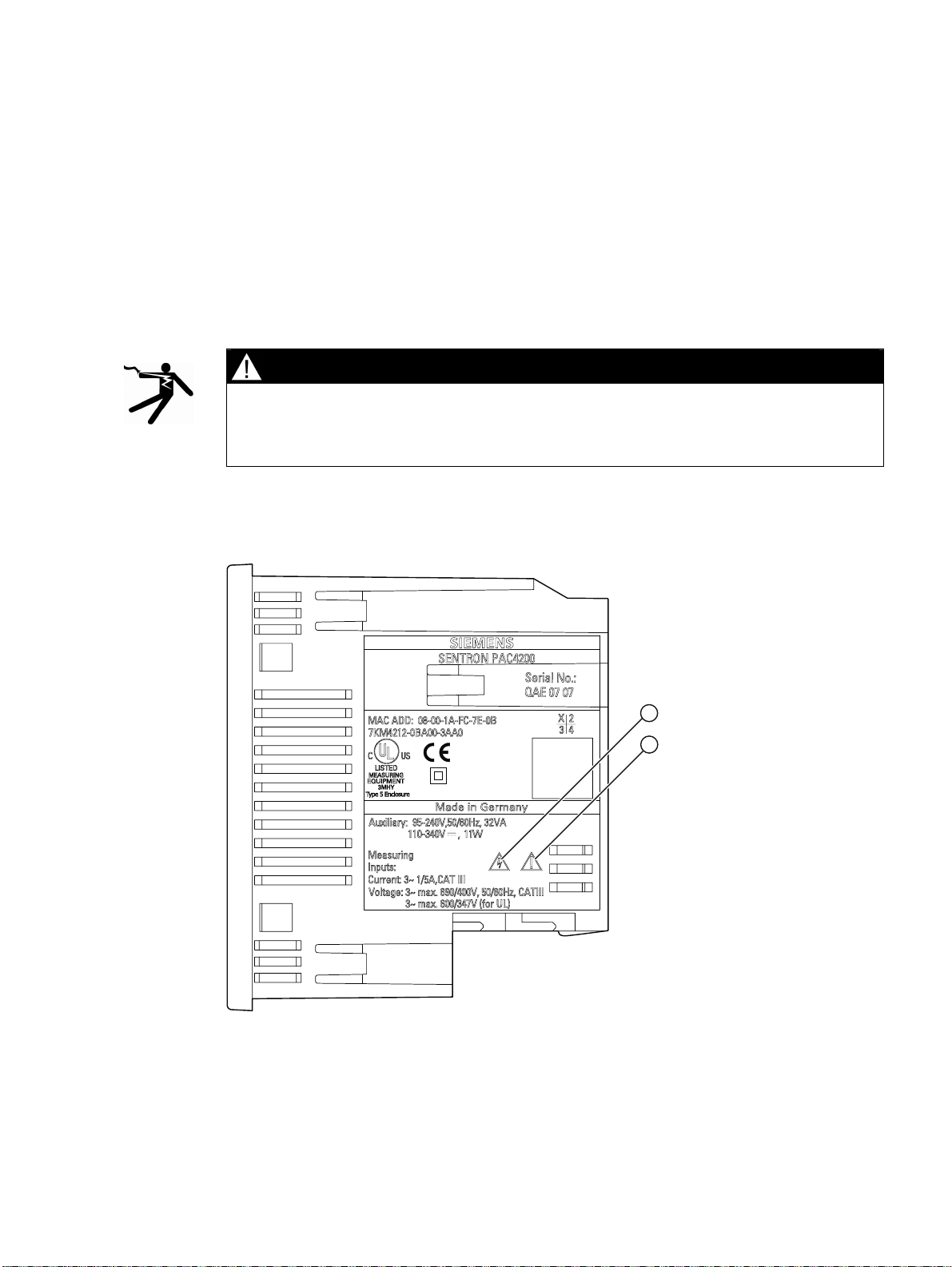
Safety-related symbols on the device
2
Figure 2-1 Safety-related symbols on the device
SENTRON PAC4200
System Manual, 09/2009, A5E02316180B-02
17
Page 18
Safety instructions
2.1 Safety notes
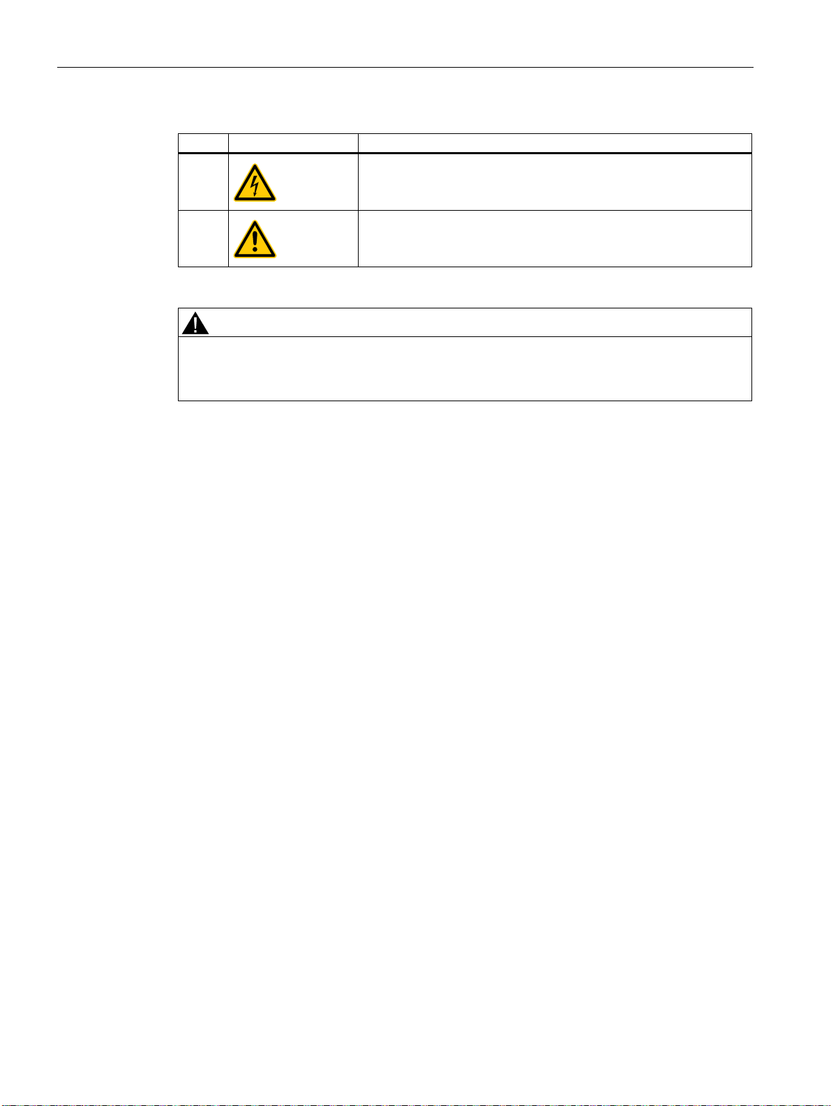
Symbol Meaning
(1)
Danger of electric shock.
See also
(2)
General Warning Symbol.
CAUTION
An open circuit can result in personal injury and damage to the unit
Short-circuit the secondary connections of intermediate current transformers at the
transformers before interrupting the current lines to the device.
Applying the measuring current (Page 111)
Applying the measuring voltage (Page 111)
Applying the supply voltage (Page 101)
Replacing the battery (Page 170)
SENTRON PAC4200
18 System Manual, 09/2009, A5E02316180B-02
Page 19

Description
3.1 Performance features of the SENTRON PAC4200
SENTRON PAC4200 is a Power Monitoring Device for displaying, storing, and monitoring all
relevant system parameters in low-voltage power distribution. It is capable of single-phase,
two-phase, or three-phase measurement and can be used in two-wire, three-wire, four-wire,
TN, TT, and IT systems.
Thanks to its compact design in 96 x 96 mm format, it fits into any standard cutout. The
SENTRON PAC4200 measures around 200 electrical variables with minimum values,
maximum values and demands.
With its large measured voltage range, SENTRON PAC4200 with a wide-voltage power
supply can be connected direct in any low-voltage system up to a rated system voltage of
690 V (max. 600 V for Vph).
Higher voltages can be measured using voltage transformers. For measuring current, either
x / 1 A or x / 5 A current transformers can be used.
The large graphical LC display permits reading even from a distance. SENTRON PAC4200
has adjustable backlighting for optimal readability even under poor lighting conditions.
The combination of four function keys with the multi-language plaintext displays makes
intuitive user prompting possible. The experienced operator can also use direct navigation
for quicker selection of the desired display menu.
3
SENTRON PAC4200 guarantees high measuring accuracy. It can be used to capture and
store load profiles according to various methods. It has a range of useful monitoring,
diagnostics, and service functions, a two-tariff apparent energy, active energy and reactive
energy counter, two universal counters, and an operating hours counter for monitoring
connected loads.
The SENTRON PAC4200 saves the apparent, active and reactive energy consumption per
day and tariff over one year. In addition, the Power Monitoring Device has an apparent,
active and reactive energy counter for recording the energy consumption of a manufacturing
process. A separate operating hours counter calculates the duration of this process. The
available digital inputs are used to control the process energy counters.
A comprehensive, parameterizable signaling system allows application-specific monitoring of
various events, such as limit violations or operator interventions.
The data memory of the device and the internal clock are battery-backed.
The integral 10 / 100 Mbit Ethernet interface or an optional expansion module can be used
for communication, e.g. the SENTRON PAC RS485 expansion module or the SENTRON
PAC PROFIBUS DP expansion module.
SENTRON PAC4200 has two multifunctional digital inputs and two multifunctional digital
outputs.
SENTRON PAC4200
System Manual, 09/2009, A5E02316180B-02
19
Page 20

Description
3.1 Performance features of the SENTRON PAC4200
With optional SENTRON PAC 4DI/2DO expansion modules, it is possible to expand the
SENTRON PAC4200 with up to 8 digital inputs and up to 4 digital outputs. This makes a
maximum configuration of 10 digital inputs and 6 digital outputs possible. The external digital
inputs and digital outputs have the same functions as the integral digital inputs and digital
outputs. Thanks to the internal power supply, the digital inputs and digital outputs of the
expansion modules can be used as S0 interfaces in accordance with IEC 62053-31. This
also enables the use of simple floating contacts for wiring the digital inputs.
The parameters can be set either direct on the device or with the SENTRON powerconfig
configuration software.
Password protection is integrated to guard against unauthorized access.
Measurement
● Derivation of more than 300 measured variables from the basic measured variables with
maximum and minimum values (min/max pointer function).
● At the voltage terminals, SENTRON PAC4200 can be connected direct to 690 V industrial
systems (max. 600 V for Vph, measuring category III, pollution degree 2). Higher voltages
using voltage transformers.
● For current transformers x/1 A and x/5 A. Conversion ratio and current direction
programmable.
● Can be used in 2-, 3- and 4-wire systems. Suitable for TN, TT and IT systems.
● High measuring accuracy: For instance, accuracy class 0.2 in accordance with IEC
61557-12 for the active energy, in other words accuracy equivalent to 0.2% of the
measured value under reference conditions.
● Calculation of genuine r.m.s values for voltage and current to the 63rd harmonic
● 4-quadrant measurement (import and export)
● Zero blind measurement
Sliding window demand values
● Calculation of the sliding window demand values for
– Voltages and currents
– Power factor per phase and total system
– Apparent, active, and reactive power per phase as well as total power
● Maximum and minimum values of the sliding window demand with the date and time of
occurrence since startup, the last reset, or the last deletion
● Demand calculation for reactive power VAR
power VAR
● Configurable averaging time.
, reactive power VARn, or total reactive
1
.
tot
SENTRON PAC4200
20 System Manual, 09/2009, A5E02316180B-02
Page 21

Description
3.1 Performance features of the SENTRON PAC4200
Average values over all phases
● Calculation of the average voltage and current values over all phases. The average value
of a three or four-phase system corresponds to the arithmetic mean for the individual
phase values.
● Maximum and minimum average values with date and time.
Counters
● A total of 10 energy counters capture reactive energy, apparent energy, and active
energy for off-peak and on-peak, import and export.
● Energy consumption for active energy, reactive energy and apparent energy per day and
tariff for 366 days.
● Two configurable universal counters for counting
– Limit violations
– Status changes at the digital input
– Status changes at the digital output
– Pulses of a connected pulse encoder, such as electricity, gas, or water meters. The
pulse shape and dynamic response must correspond to the signal shape described in
the IEC 62053-31 standard
● Operating hours counter for monitoring the operating time of a connected load. Counts
only in the case of energy counting above an adjustable threshold
● One apparent energy counter, one active energy counter, and one reactive energy
counter for detecting the total energy import, regardless of the active tariff for display on
the device
● One apparent energy counter, one active energy counter, and one reactive energy
counter for detecting the power consumption of a manufacturing process. The process
energy counters can be started and stopped by means of the available digital inputs.
● Operating hours counter for recording the duration of a manufacturing process. Starting
and stopping is carried out with the start command and the stop command of the digital
input that controls the process energy counter.
● Up to 10 counters for detecting the consumption of any media via digital inputs. The
consumption of gas, water, compressed air, electrical current, etc. can thus be recorded
using simple media counters with pulse input.
The display texts can be freely parameterized in a user-friendly way using the
SENTRON powerconfig
configuring software.
SENTRON PAC4200
System Manual, 09/2009, A5E02316180B-02
21
Page 22

Description
3.1 Performance features of the SENTRON PAC4200
Monitoring functions
The following can be monitored:
● 12 limits The limit values can be logically combined. A group message that indicates the
violation of at least one limit value can be generated.
● Direction of rotation.
● Status of the digital inputs.
● Operating status of SENTRON PAC4200.
● Resetting the device and the communication parameters to the factory default settings.
● Deleting recorded load profiles and events
● Resetting counter values
● Reboot after losing the power supply.
● Detection and logging of failures in the measuring voltage and the supply voltage with
date and time-of-day
● Monitoring of phase symmetry for voltage and current to avoid load unbalance
● Operating hours counter for monitoring the runtime of connected loads such as motors,
pumps or machines, etc.
● Event-driven switching of the digital outputs possible
● Changing the date and the time.
● Changing device parameters.
● Writing a large number of events in the event memory.
Events and messages
● Recording up to 4096 events with a time stamp and event-specific information.
● Displaying the events in an events list.
● Reporting the events on the display.
● Classifying the messages as information, warnings, or alarms.
Displays and controls
● Large backlit graphics LC display for optimal readability even from a distance.
● Menu-driven parameterization and operation with plaintext display.
● Choice of output language for menu and text displays.
● Phase labels selectable (L1, L2, L3 <=> a, b, c).
User-definable display of measurements
● Freely definable display of up to four measurements (digital display or bar diagram).
SENTRON PAC4200
22 System Manual, 09/2009, A5E02316180B-02
Page 23

Description
3.1 Performance features of the SENTRON PAC4200
User-definable display of counters
● Up to 5 displays for counters that can be labeled individually
Interfaces
● Integrated Ethernet interface.
● Two slots for operating optional expansion modules.
SENTRON PAC4200 supports a maximum of one communication module, e.g.
SENTRON PAC PROFIBUS DP or SENTRON PAC RS485. The second slot can be used
for other expansion modules.
Gateway
Gateway function:
This allows devices that only support serial communication (RS 485) to be addressed via
Ethernet.
● Modbus gateway for integrating purely Modbus RTU slaves into an Ethernet network
(Ethernet Modbus TCP <=> RS 485 Modbus RTU)
● Serial gateway for connecting RS 485 devices that support Modbus RTU and similar
Internal clock
● Time stamping of events.
● Synchronization of the load profile as an alternative to external synchronization.
● Battery backup.
Long-term memory
● Storage of load profiles.
● Storage of events.
● Battery backup.
Inputs and outputs
● Two multifunctional integral digital inputs for tariff switching, time synchronization,
● Two multifunctional integral digital outputs, programmable as pulse outputs for active
protocols
demand period synchronization, status monitoring, or capturing energy pulses from thirdparty devices.
energy or reactive energy pulses, for showing the direction of rotation, indicating the
operating hours of SENTRON PAC4200, representing limit violations, or as switching
outputs for remote control via PC.
● Up to 2 plug-in SENTRON PAC 4DI/2DO expansion modules with the same functions as
the integral digital inputs and digital outputs
This results in a maximum configuration of 10 digital inputs and 6 digital outputs.
SENTRON PAC4200
System Manual, 09/2009, A5E02316180B-02
23
Page 24

Description
3.2 Measuring inputs
Protection
Password protection by means of a 4-character code.
See also
Measured variables (Page 25)
Technical data (Page 175)
Sliding window demand values (Page 31)
3.2 Measuring inputs
Current measurement
CAUTION
Alternating current measurement only, otherwise the device will become non-functional
Use the device to measure alternating current only.
SENTRON PAC4200 is designed for:
● Measuring current of 1 A or 5 A for connecting current transformers. Each current
measuring input can take a continuous load of 10 A. Surge withstand capability is
possible for currents up to 100 A and a duration of 1 s.
Voltage measurement
CAUTION
Alternating voltage measurement only, otherwise the device will become non-functional
Use the device to measure alternating voltage only.
SENTRON PAC4200 is designed for:
● Direct measurement on the system or using voltage transformers. The measuring voltage
inputs of the device measure direct via protective impedances. External voltage
transformers are required to measure higher voltages than the permissible rated input
voltages.
● Measuring voltage up to 400 V / 690 V (max. 347 V / 600 V for Vph) on devices with a
wide-voltage power supply. The device is designed for measuring input voltages up to
400 V (347 V for Vph) phase-to-neutral and 690 V (600 V for Vph) phase-to-phase.
SENTRON PAC4200
24 System Manual, 09/2009, A5E02316180B-02
Page 25

Description
3.3 Measured variables
Connection types
Five connection types have been provided for connecting two-wire, three-wire or four-wire
systems with balanced or unbalanced load.
Table 3- 1 Available connection types
Short code Connection type
3P4W 3 phases, 4 conductors, unbalanced load
3P3W 3 phases, 3 conductors, unbalanced load
3P4WB 3 phases, 4 conductors, balanced load
3P3WB 3 phases, 3 conductors, balanced load
1P2W Single-phase AC
The input circuit of the device must correspond to one of the connection types listed. Select
the suitable connection type for the purpose.
CAUTION
Improper Power Supply May Damage Equipment
Before connecting the SENTRON PAC, you must ensure that the local power supply
conditions agree with the specifications on the type plate.
You can find connection examples in the chapter "Connecting".
The short code of the connection type must be entered in the device settings at startup. You
can find the instructions for parameterizing the connection type in the chapter "Starting up".
See also
Connecting (Page 79)
Set the connection type (Page 106)
Applying the measuring voltage (Page 111)
Applying the measuring current (Page 111)
3.3 Measured variables
Measured variables - overview
The table below lists all measured variables that the device records or derives from basic
variables. You can find more information on measured variables in the Appendix.
SENTRON PAC4200
System Manual, 09/2009, A5E02316180B-02
25
Page 26

Description
3.3 Measured variables
Inst Instantaneous value
Min Minimum value
Max Maximum value
DMD Demand value
Σ Total
Designation Root-mean-
square value
Inst Min Max Inst Min Max DMD Min Max
Voltage ph-n
V
a-n
/ V
b-n
/ V
✓ ✓ ✓ ✓ ✓ ✓ ✓ ✓ ✓ [V]
c-n
Voltage ph-ph
V
a-b
/ V
b-c
/ V
✓ ✓ ✓ ✓ ✓ ✓ ✓ ✓ ✓ [V]
c-a
Current
Ia / Ib / Ic ✓ ✓ ✓ ✓ ✓) ✓ ✓ ✓ ✓ [A]
Neutral current
In ✓ ✓ ✓ ✓ ✓ ✓ [A]
Apparent power per phase
VAa / VAb / VAc ✓ ✓ ✓ ✓ ✓ ✓ [VA]
Active power per phase import/export
Wa / ±Wb / ±Wc ✓ ✓ ✓ ✓ ✓ ✓ [W]
Total reactive power (VARtot) per phase positive / negative
VAR
tot a
; VAR
tot b
; VAR
✓ ✓ ✓ ✓ ✓ ✓ [VAR]
tot c
Reactive power (VAR1) per phase positive / negative
VAR
1 a
; VAR
1 b
; VAR
✓ ✓ ✓ ✓ ✓ ✓ [VAR]
1 c
Reactive power (VARn) per phase positive / negative
VAR
n a
; VAR
n b
; VAR
✓ ✓ ✓ ✓ ✓ ✓ [VAR]
n c
Total apparent power over all phases
VA ✓ ✓ ✓ ✓ ✓ ✓ [VA]
Total active power over all phases import / export
W ✓ ✓ ✓ ✓ ✓ ✓ [W]
Total reactive power (VARtot) over all phases positive / negative
VAR
✓ ✓ ✓ ✓ ✓ ✓ [VAR]
tot
Total reactive power VAR1 over all phases positive / negative
VAR1 ✓ ✓ ✓ ✓ ✓ ✓ [VAR]
Total reactive power VARn over all phases positive / negative
VARn ✓ ✓ ✓ ✓ ✓ ✓ [VAR]
Power factor of the fundamental
cosφ a / cosφ b / cosφc ✓ ✓ ✓ –
Power factor
|PFa| / |PFb| / |PFc| ✓ ✓ ✓ ✓ ✓ ✓ –
Average over 3
1)
phases
Sliding window
demand
Σ Unit
SENTRON PAC4200
26 System Manual, 09/2009, A5E02316180B-02
Page 27

Description
3.3 Measured variables
Designation Root-mean-
square value
Average over 3
1)
phases
Sliding window
demand
Σ Unit
Inst Min Max Inst Min Max DMD Min Max
Total power factor
PF ✓ ✓ ✓ ✓ ✓ ✓ –
Line frequency
f ✓ ✓ ✓ [Hz]
Displacement angle
φa / φb / φc ✓ ✓ ✓ [°]
Phase angle
X
a-a
/ X
a-b
/ X
✓ [°]
a-c
THD voltage for ph-n referred to the fundamental
THD
V a
/ THD
V b
/ THD
✓ ✓ [%]
V c
THD voltage for ph-ph referred to the fundamental
THD
V a-b
/ THD
V b-c
/ THD
✓ ✓ [%]
V c-a
THD current referred to the fundamental
THD
/ THD
I a
/ THD
I b
✓ ✓ [%]
I c
Apparent energy
E
✓ [VAh]
ap T
Active energy import/export
E
Reactive energy import/export
E
, E
a T imp
r T imp,Er T exp
a T exp
✓ [Wh]
2)
✓ [VARh]
Unbalance voltage
UnbalV ✓ [%]
Unbalance current
UnbalI ✓ [%]
Current distortion
I
, I
, I
d a
✓ ✓ [A]
d b
d c
Fundamental voltage ph-n
h
1 a
, h
, h
✓ [V]
1 b
1 c
Harmonic content of the 3rd, 5th, 7th, ... 31st harmonics for the ph-n voltage referred to the fundamental
h
h
h
3 a-n
3 b-n
3 c-n
… h
… h
… h
31 a-n
31 b-n
31 c-n
✓ ✓ [%]
Fundamental voltage ph-ph
h
1 a-b
, h
1 b-c
, h
✓ [V]
1 c-a
Harmonic content of the 3rd, 5th, 7th, ... 31st harmonics for the ph-ph voltage referred to the fundamental
h
h
h
3 a-b
3 b-c
3 c-a
… h
… h
… h
31 a-b
31 b-c
31 c-a
✓ ✓ [%]
Current of the fundamental and current of the 3rd, 5th, 7th, ... 31st harmonics in the phase conductor
I
… I
… I
… I
31 a
31 b
31 c
1 a
I
1 b
I
1 c
✓ ✓ [A]
SENTRON PAC4200
System Manual, 09/2009, A5E02316180B-02
27
Page 28

Description
3.3 Measured variables
Designation Root-mean-
square value
Average over 3
1)
phases
Sliding window
demand
Σ Unit
Inst Min Max Inst Min Max DMD Min Max
2 universal counters
✓
3)
Operating hours counter
Oper hours (load runtime) ✓ [s]
4)
([h])
Process apparent energy
E
✓ [VAh]
ap prc
Process active energy import
E
, ✓ [Wh]
a prc imp
Process reactive energy import
E
, ✓ [VARh]
r prc imp
Day counter for apparent energy
E
✓ [VAh]
ap day
Day counter for active energy import/export
E
a day imp
, E
✓ [Wh]
a day exp
Day counter for reactive energy import/export
E
r day imp,Er day exp
✓ [VARh]
1) The average over 3 phases can only be called via the communication interfaces or the user defined display.
2) Optionally calculated for total reactive power (VARtot), reactive power (VARn), or reactive power (VAR1).
3) The unit depends on the settings: User definable unit or "kWh" or "kVARh" for the pulse counter function.
4) The operating hours are available via the bus in seconds. They are displayed in hours on the device display.
See also
Measured variables (Page 199)
Measured variables depending on the connection type
The total set of representable measured variables is restricted by the method of connecting
the device.
A measured value that cannot be indicated because of the connection method is shown on
the display by means of a broken line "----".
The table below shows which measured values can be represented depending on the
connection type.
Table 3- 2 Display of the measured variables depending on the connection type
Connection type
Measured variable
Voltage a-n ✓ - ✓ - ✓
Voltage b-n ✓ - - - Voltage c-n ✓ - - - -
SENTRON PAC4200
28 System Manual, 09/2009, A5E02316180B-02
3P4W 3P3W 3P4WB 3P3WB 1P2W
Page 29

Description
3.3 Measured variables
Connection type
Measured variable
3-phase average voltage ph-n ✓ - - - Voltage a-b ✓ ✓ - ✓ Voltage b-c ✓ ✓ - ✓ Voltage c-a ✓ ✓ - ✓ 3-phase average voltage ph-ph ✓ ✓ - ✓ Current a ✓ ✓ ✓ ✓ ✓
Current b ✓ ✓ - - Current c ✓ ✓ - - 3-phase average current ✓ ✓ - - Neutral current ✓ - - - Apparent power a ✓ - - - Apparent power b ✓ - - - Apparent power c ✓ - - - Active power a ✓ - - - Active power b ✓ - - - Active power c ✓ - - - Total reactive power a (VARtot)1) ✓ - - - -
Total reactive power b (VARtot)1) ✓ - - - -
Total reactive power c (VARtot)1) ✓ - - - -
Reactive power a (VAR1)1) ✓ - - - -
Reactive power b (VAR1)1) ✓ - - - -
Reactive power c (VAR1)1) ✓ - - - -
Reactive power a (VARn)1) ✓ - - - -
Reactive power b (VARn)1) ✓ - - - -
Reactive power c (VARn)1) ✓ - - - -
Total apparent power over all phases ✓ ✓ ✓ ✓ ✓
Total active power over all phases ✓ ✓ ✓ ✓ ✓
Total reactive power (VARtot) over all phases1) ✓ ✓ ✓ ✓ ✓
Total reactive power (VAR1) over all phases1) ✓ ✓ ✓ ✓ ✓
Total reactive power (VARn) over all phases1) ✓ ✓ ✓ ✓ ✓
Cos φ a ✓ - ✓ ✓ ✓
Cos φ b ✓ - - - Cos φ c ✓ - - - Power factor a ✓ - - - Power factor b ✓ - - - Power factor c ✓ - - - Total Power Factor ✓ ✓ ✓ ✓ ✓
Line frequency ✓ ✓ ✓ ✓ ✓
Displacement angle a ✓ - ✓ ✓ ✓
Displacement angle b ✓ - - - Displacement angle c ✓ - - - -
3P4W 3P3W 3P4WB 3P3WB 1P2W
SENTRON PAC4200
System Manual, 09/2009, A5E02316180B-02
29
Page 30

Description
3.3 Measured variables
Connection type
Measured variable
Phase angle a-a ✓ ✓ - ✓ Phase angle a-b ✓ ✓ - ✓ Phase angle a-c ✓ ✓ - ✓ THD voltage a ✓ - ✓ - ✓
THD voltage b ✓ - - - THD voltage c ✓ - - - THD voltage a-b ✓ ✓ - ✓ THD voltage b-c ✓ ✓ - ✓ THD voltage c-a ✓ ✓ - ✓ THD current a ✓ ✓ ✓ ✓ ✓
THD current b ✓ ✓ - - THD current c ✓ ✓ - - Apparent energy ✓ ✓ ✓ ✓ ✓
Active energy import, export ✓ ✓ ✓ ✓ ✓
Reactive energy import, export ✓ ✓ ✓ ✓ ✓
Unbalance voltage ✓ - - - Unbalance current ✓ ✓ - - Amplitude unbalance voltage ✓ - - - Amplitude unbalance current ✓ ✓ - - Distortion current a ✓ ✓ ✓ ✓ ✓
Distortion current b ✓ ✓ - - Distortion current c ✓ ✓ - - Harmonic content of the 3rd, 5th, 7th, ... 31st harmonics for the a-
n voltage referred to the fundamental
Harmonic content of the 3rd, 5th, 7th, ... 31st harmonics for the b-
n voltage referred to the fundamental
Harmonic content of the 3rd, 5th, 7th, ... 31st harmonics for the c-
n voltage referred to the fundamental
Harmonic content of the 3rd, 5th, 7th, ... 31st harmonics for the a-
b voltage referred to the fundamental
Harmonic content of the 3rd, 5th, 7th, ... 31st harmonics for the b-
c voltage referred to the fundamental
Harmonic content of the 3rd, 5th, 7th, ... 31st harmonics for the c-
a voltage referred to the fundamental
Current of the fundamental and current of the 3rd, 5th, 7th, ...
31st harmonics in a
Current of the fundamental and current of the 3rd, 5th, 7th, ...
31st harmonics in b
Current of the fundamental and current of the 3rd, 5th, 7th, ...
31st harmonics in c
Universal Counter ✓ ✓ ✓ ✓ ✓
Operating Hours Counter ✓ ✓ ✓ ✓ ✓
1) You can set which type of reactive power (VAR1, VARtot, or VARn) is displayed with the configuration software. All three
reactive power types can be called via the interface.
3P4W 3P3W 3P4WB 3P3WB 1P2W
✓ - ✓ - ✓
✓ - - - -
✓ - - - -
✓ ✓ - ✓ -
✓ ✓ - ✓ -
✓ ✓ - ✓ -
✓ ✓ ✓ ✓ ✓
✓ ✓ - - -
✓ ✓ - - -
SENTRON PAC4200
30 System Manual, 09/2009, A5E02316180B-02
Page 31
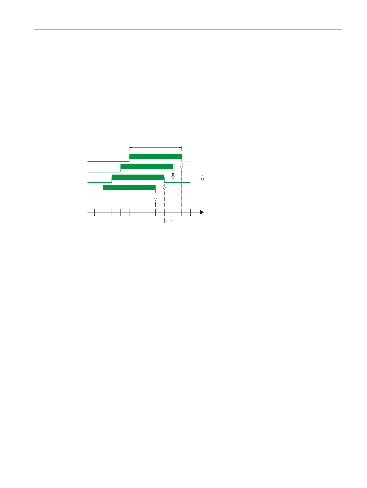
Description
3.3 Measured variables
See also
Connection examples (Page 87)
3.3.1 Sliding window demand values
The sliding window demand value is the arithmetic mean of all measured values that occur
within a configurable averaging time. "Sliding" means that the interval for the demand
calculation is continuously shifted as a function of time.
&RQILJXUHG
DYHUDJLQJWLPH
6OLGLQJZLQGRZGHPDQGRYHU
DYHUDJLQJWLPH
Figure 3-1 Sliding window demand
The sliding window demand values are updated 60 times per set averaging time. A lower
limit of 200 ms applies here. If an averaging time of 3, 5 or 10 seconds is set, the demand
value is formed with fewer values.
Available sliding window demand values
SENTRON PAC4200 supplies sliding window demand values for a large number of
measured variables:
● Per phase or as a total value over all phases
● With the maximum and minimum values as well as the time stamp for the maximum and
minimum values
The "Measured variables – overview" table above lists the available sliding window demand
values.
The sliding window demand values are represented on the display and can be called via the
communication interfaces.
W>V@
,QWHUYDO
5HIUHVKWLPHIRUVOLGLQJZLQGRZGHPDQG
SENTRON PAC4200
System Manual, 09/2009, A5E02316180B-02
31
Page 32

Description
3.3 Measured variables
Representation on the display
A stroke (bar) above the phase designation (a, b, c) indicates that the displayed value is a
sliding window demand value.
Figure 3-2 Maximum sliding window demand of the active power
You can display the sliding window demand with function key F1: First select the measured
variable. Then scroll to the demand display with F1.
Parameterization of the averaging time
The averaging time can be parameterized on the display or via the communication interface.
The following can be set: 3, 5, 10, 30, 60, 300, 600, 900 seconds.
See also
Measured variables (Page 25)
Basic parameters (Page 137)
MODBUS (Page 225)
3.3.2 Other properties of measured variable representation
Zero point suppression level
The zero point suppression level can be set via the interface in 1% steps in the range from
0% to 10% of the primary rated value of the external current transformer (default value
0.0%). Currents within this range are indicated on the display with "0" (zero).
Current direction
The current direction can be changed on the device or via the interface individually for each
phase. It is not necessary to change the terminal connections of the current transformers in
the event of connection errors.
SENTRON PAC4200
32 System Manual, 09/2009, A5E02316180B-02
Page 33

Description
3.4 Load profile
3.4 Load profile
3.4.1 Overview
The load profile records the time history of the electric power and thus documents the
distribution of power fluctuations and peaks.
SENTRON PAC4200 supports load profile recording according to the "fixed block" or "rolling
block" method. With both methods, the load profile is stored in the device and made
available at the communication interfaces.
SENTRON PAC4200 is capable of intelligently interpreting synchronization signals received
at irregular intervals. Any deviations from the set times are documented in the load profile.
Accessing the load profile data
Note
Data access via the software
Current and historical load profile data can only be accessed via the communication
interfaces. For more information, please see the related documentation.
Configuring load profile recording
You can adapt load profile recording using the configuration software or on the display of the
device. The following parameters influence the recording:
● Length of the demand period or subperiod
● Number of subperiods per demand period. This number defines the method for recording
the load profile ("fixed block" or "rolling block")
● Type of synchronization
You can also set the following parameter with the configuration software:
● Type of reactive power VAR
You can find more information about parameterization on the device display in the chapter
"Parameterizing", "Power demand".
Changing the configuration during operation: If the period length or the number of subperiods
is changed, this directly influences the load profile recording. The device stops the current
recording and clears all data in the load profile memory. Changing the configuration has no
effect on the device counter. The device is not reset.
, VAR1, or VARn
tot
Load profile recording methods
SENTRON PAC4200 supports the following load profile recording methods:
● Fixed block
● Rolling block
The default setting is the fixed block method with a demand period length of 15 minutes.
SENTRON PAC4200
System Manual, 09/2009, A5E02316180B-02
33
Page 34
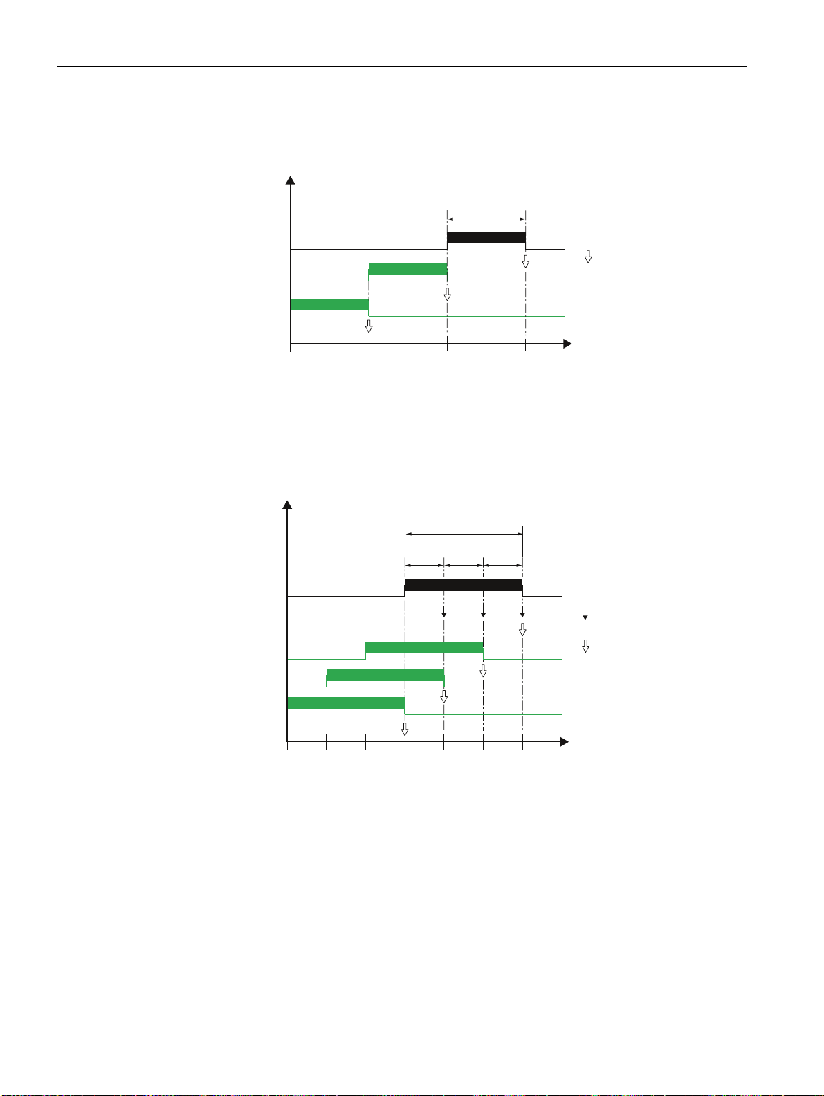
Description
3.4 Load profile
Fixed block method
The load profile data is calculated and stored at the end of each demand period.
'HPDQG
SHULRG
Figure 3-3 Load profile, fixed block method
Rolling block method
The rolling block method divides the demand period into subperiods. The load profile data is
calculated and stored at the end of each demand period or subperiod.
'HPDQGSHULRG
'HPDQGSHULRG
'HPDQGSHULRG
'HPDQGSHULRG
'HPDQGSHULRG
'HPDQGSHULRG
'HPDQGSHULRG
6XESHULRGV
(QGRI
GHPDQGSHULRG
W>PLQ@
(QGRI
VXESHULRG
(QGRI
GHPDQGSHULRG
'HPDQGSHULRG
W>PLQ@
Figure 3-4 Load profile, rolling block method
Parameterizing the fixed block and rolling block methods
SENTRON PAC4200 supports the fixed block method as a special case of the rolling block
method. The most important distinguishing feature is the number of subperiods.
Number of subperiods:
The demand period can be divided into a maximum of five subperiods.
● The number "1" defines the fixed block method. In this case, the length of the subperiod
is identical to the length of the demand period.
● The numbers "2" to "5" define the rolling block method.
SENTRON PAC4200
34 System Manual, 09/2009, A5E02316180B-02
Page 35

Description
3.4 Load profile
Length of the subperiods:
The length of a subperiod is an integer part of a full hour. The device allows the following
lengths in minutes:
1, 2, 3, 4, 5, 6, 10, 12, 15, 20, 30, 60 min
Length of demand period:
The length of the demand period cannot be directly configured. It is defined as the product of
the length of a subperiod and the number of subperiods.
Length
demand_period
= n • length
; n = number of subperiods
subperiod
Calculation of the power demand and the cumulated power
Arithmetic power demand:
Arithmetic calculation of the power demand referred to the actual length of the demand
period. The arithmetic power demand in the instantaneous period remains constant providing
the power is constant.
Cumulated power:
See also
Cumulative calculation of the power referred to the configured length of the subperiod. The
cumulated power in the instantaneous period increases linearly providing the power is
constant.
The energy can be calculated from the cumulated power as follows:
Energy = (cumulated power) • (configured period length)
Power demand (Page 141)
SENTRON PAC4200
System Manual, 09/2009, A5E02316180B-02
35
Page 36
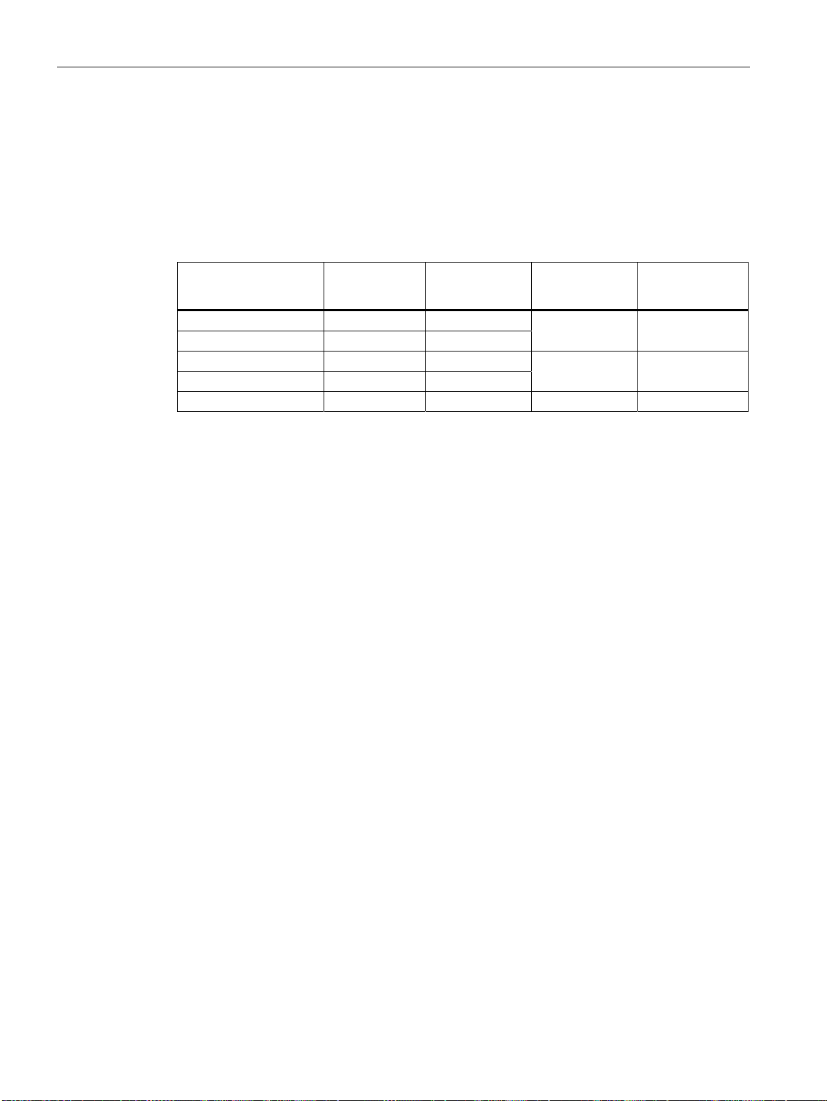
Description
3.4 Load profile
3.4.2 Historical load profile
Measured variables recorded
SENTRON PAC4200 records the following measured variables:
Table 3- 3 Historical load profile
Measured variable Cumulated
Active power import X X
Active power export X X
Reactive power import X X
Reactive power export X X
Apparent power X X X X
The values are recorded per demand period or subperiod:
● Fixed block method
All values are recorded per demand period.
● Rolling block method
Arithmetic power demand values are recorded per demand period.
Cumulated power demand values and maximum / minimum values are recorded per
subperiod.
Accessing the load profile memory
● The complete load profile memory can be read out.
● A definable number of periods can be read out starting at a definable period number.
power
Power
demand
Minimum
instantaneous
value
±X ±X
±X ±X
Maximum
instantaneous
value
● The complete load profile memory can be cleared.
Storage concept of the load profile memory
The memory of SENTRON PAC4200 is designed as a circular buffer. If the maximum
available memory is exceeded, the oldest data is overwritten by the newest data.
SENTRON PAC4200
36 System Manual, 09/2009, A5E02316180B-02
Page 37

Description
3.4 Load profile
Storage capacity of the load profile memory
The data volume that occurs when a load profile is recorded depends on the length of the
period.
SENTRON PAC4200 can record load profile data for the following configuration over a
period of 40 days:
● Fixed block:
Length of the demand period: 15 minutes
● Rolling block:
Length of the subperiods: 15 minutes
This corresponds to a maximum of 3840 recorded periods.
This calculation applies to the ideal case in which the actual period length is identical to the
configured length for all periods over the complete load profile recording time. Any deviations
between the actual and configured period lengths additionally increase the data volume.
3.4.3 Current load profile data at the communication interfaces
Current load profile data
SENTRON PAC4200 supplies the load profile data for the current and instantaneous periods
at the communication interfaces.
● The current period is the last completed period.
● The instantaneous period is the period still in progress and has not yet been completed.
You can find more information on accessing the data via MODBUS in the Appendix.
See also
Measured variables for the load profile with the function codes 0x03 and 0x04 (Page 235)
3.4.4 Synchronization of the load profile
Synchronization time
The device expects the synchronization pulse at the start of the period.
SENTRON PAC4200
System Manual, 09/2009, A5E02316180B-02
37
Page 38

Description
3.4 Load profile
Synchronization types
The device can obtain the synchronization pulse from an external source
● As a signal at the digital input,
● As a command via the communication interfaces.
The device can control the synchronization itself
● By means of the internal clock.
Handling of irregular, external synchronization pulses
SENTRON PAC4200 checks whether the external synchronization pulse is received at the
set time, too soon, too late, or not at all. If the deviation from the set time exceeds a defined
tolerance, this results in a shorter period.
If the complete time frame for received pulses is offset, SENTRON PAC4200 automatically
adapts to the new time frame.
Synchronization via the communication interface
The synchronization frame contains the length of the subperiod in minutes. The
synchronization command is ignored if the period length sent to the device with the
synchronization frame is different to the length parameterized in the device.
Synchronization with the internal clock
The length of the subperiod, and thus also the demand period, is determined solely by the
internal clock.
A subperiod starts on the full hour plus a multiple of the configured subperiod length.
Correction of the time during the current demand period or beyond the end of the demand
period results in shorter demand periods. SENTRON PAC4200 marks these periods with the
valuation indicator "resynchronized".
It does not record any substitute values for the gaps that are created in the time history.
Response to powering up
All load profiles that have already been recorded remain unchanged.
SENTRON PAC4200 resets the internal clock if it detects load profiles with a date in the
future or a time in the past on powering up.
Impact of a tariff change on the load profile
Tariff changes between off-peak and on-peak have an impact on the load profile because all
values stored in the profile are uniquely assigned to the applicable tariff.
The old tariff remains valid until the end of the instantaneous period. The new tariff takes
effect at the start of the next period. The energy counters of SENTRON PAC4200 are
switched to the other tariff at the end of the instantaneous demand period.
SENTRON PAC4200
38 System Manual, 09/2009, A5E02316180B-02
Page 39

Description
3.5 Tariffs
Impact of a measuring voltage failure
A failure of the measuring voltage has no effect on the load profile.
Impact of a supply voltage failure
The device records shorter periods if the supply voltage fails and when it is restored.
It does not record any substitute values for the duration of the power failure.
3.4.5 Additional information about the load profile data
SENTRON PAC4200 records the following additional information for each period:
● "Resynchronized"
The period was prematurely ended by the device owing to a synchronization irregularity.
● "Supply voltage failed"
The period was prematurely ended owing to the failure of the supply voltage.
● "Unreliable"
The load profile data is unreliable.
– The measuring current or the measuring voltage is outside the specified range.
– The reactive power type has changed.
The additional information is stored together with the other load profile data and can be
called via the communication interface.
See also
Load profile (Page 225)
3.5 Tariffs
SENTRON PAC4200 supports two tariffs for the integrated energy counters (on-peak and
off-peak).
Impact of the tariff change
The tariff change affects all energy counters for active energy, reactive energy, and apparent
energy.
Controlling the tariff change
A tariff change between off-peak and on-peak can be requested by means of a digital input
or via the communication interfaces.
Time-related switching is only possible using a higher-level system.
SENTRON PAC4200
System Manual, 09/2009, A5E02316180B-02
39
Page 40
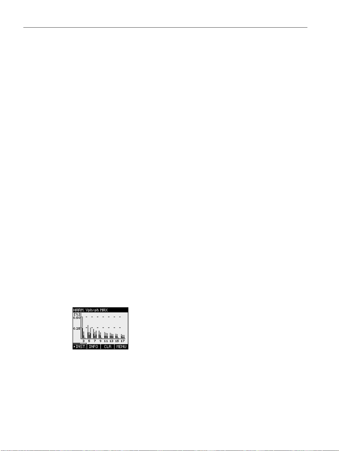
Description
3.6 Technical features of the supply quality
Activation of a tariff change at the end of a period
The old tariff remains valid until the end of the instantaneous period. The new tariff takes
effect at the start of the next period. The energy counters of SENTRON PAC4200 are
switched to the other tariff at the end of the instantaneous demand period.
Without synchronization, the tariff change takes effect immediately.
3.6 Technical features of the supply quality
The SENTRON PAC4200 supplies the following measured variables for evaluating network
quality:
1. Harmonics up to the 31st harmonic
2. THD for voltage and current:
3. Displacement angle φ
4. Cosine of the displacement angle φ
5. Phase angle
6. Unbalance voltage and unbalance current
Harmonics up to the 31st harmonic referred to the fundamental
SENTRON PAC4200 measures the 3rd to 31st odd harmonics referred to the fundamental
for:
● Voltage ph-ph
● Voltage ph-n
● Current
SENTRON PAC4200 measures the instantaneous and maximum values.
The values are represented on the display and can be called via the communication
interfaces.
The display represents the harmonics as a bar diagram and in table form with
instantaneous/maximum values and the time stamp of the maximum value.
Figure 3-5 Instantaneous and maximum values of the harmonics of the ph-ph voltage referred to the
fundamental
The fundamental of the voltage can only be read via the bus.
SENTRON PAC4200
40 System Manual, 09/2009, A5E02316180B-02
Page 41
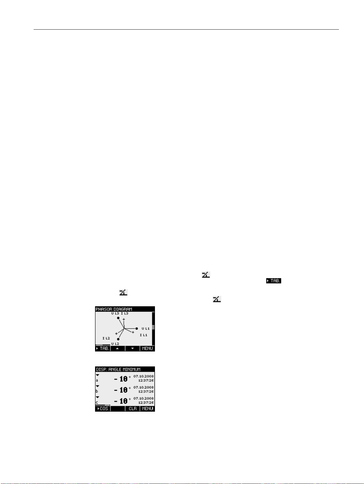
Description
3.6 Technical features of the supply quality
Harmonics referred to the root-mean-square value
The fundamental of the voltage is specified in volts (V) rather than percent (%). The
harmonics of the voltage referred to the root-mean-square value (r.m.s.) can be calculated
from this information in the software.
THD
The THD (total harmonic distortion) is used to describe the distortion of the electrical signal.
It indicates the ratio of the harmonic content to the fundamental in percent.
SENTRON PAC4200 measures the THD of the voltage and the THD of the current referred
to the fundamental. The instantaneous value, the maximum value and the time stamp of the
maximum value are supplied.
The values are calculated according to the IEC 61557-12 standard: 2007. Account is taken
of harmonics up to the 31st harmonic.
Displacement angle φ
The angle φ (phi) describes the displacement angle between the fundamentals of voltage
and current.
SENTRON PAC4200 supplies the instantaneous value of the displacement angle φ, the
maximum and minimum values, and the time stamps of the maximum and minimum values
for each phase.
The values can be read out via the communication interfaces.
The display represents the phase displacement on several screens:
● Phasor diagram,
can be called with "MAIN MENU" > "PHASOR DIAGRAM"
● Value table of the phasor diagram, row
can be called with "MAIN MENU" > "PHASOR DIAGRAM" > F1
● Display "
φ",
can be called with "MAIN MENU" > "COSφ/
φ"
φ" > F1 > F1 > F1
Figure 3-6 Graph of the phasor diagram
Figure 3-7 Minimum value of the displacement angle φ with time stamp
SENTRON PAC4200
System Manual, 09/2009, A5E02316180B-02
41
Page 42
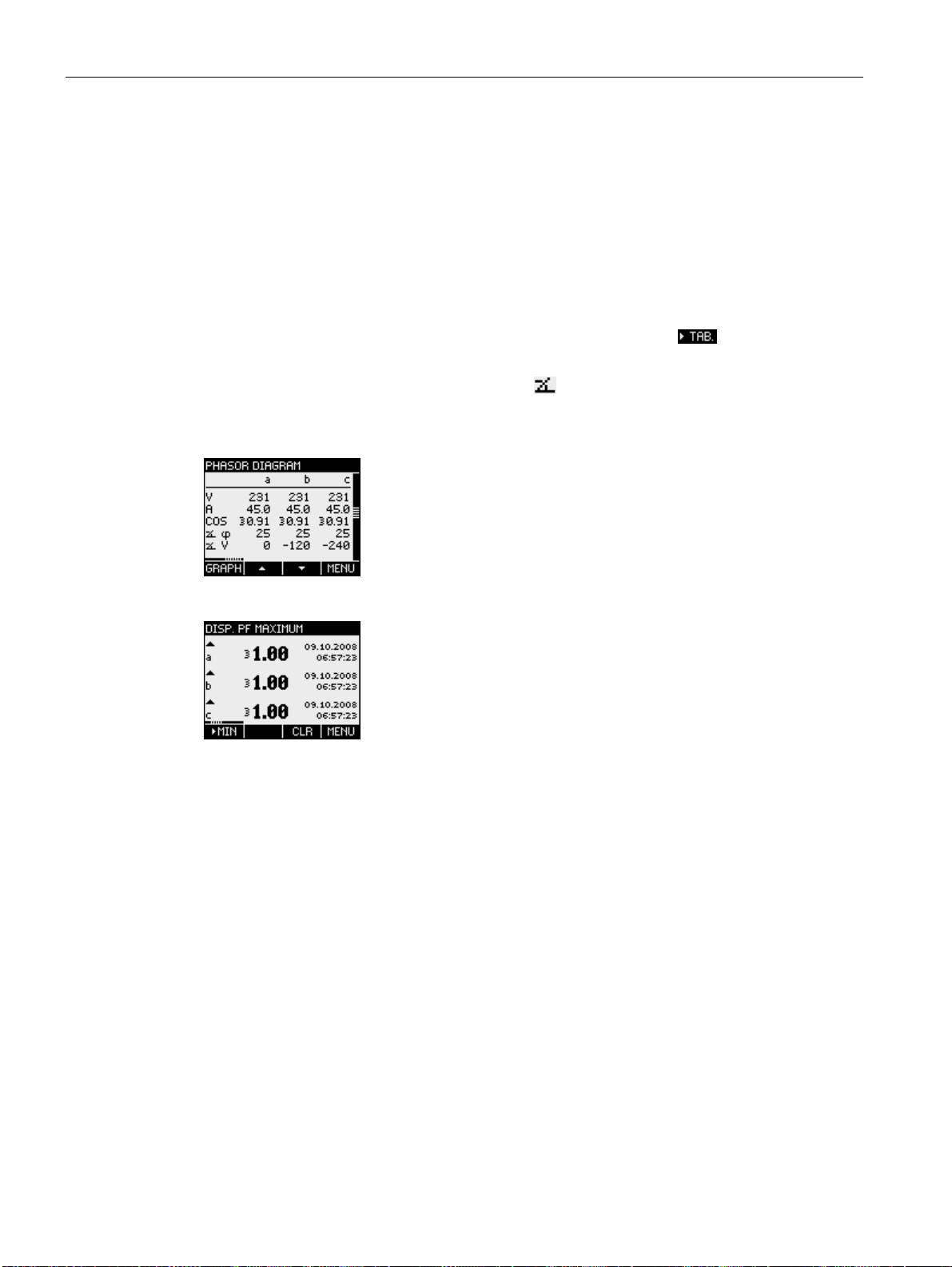
Description
3.6 Technical features of the supply quality
Cosine phi
cos φ is the cosine of the displacement angle φ of the fundamental. The possible values of
cos φ are between -1 and 1.
SENTRON PAC4200 supplies the instantaneous value of cos φ, the maximum and minimum
values, and the time stamps of the maximum and minimum time values for each phase.
The values can be read out via the communication interfaces.
The display represents cos φ on several screens:
● Value table of the phasor diagram, row "COS"
can be called with "MAIN MENU" > "PHASOR DIAGRAM" > F1
● Display "COS φ",
can be called with "MAIN MENU" > "COSφ/
φ"
An inductive cos φ is marked by a coil symbol in front of the measured value and a
capacitive cos φ by a capacitor symbol.
Phase angle
Figure 3-8 Value table for the phasor diagram
Figure 3-9 Maximum value of the displacement power factor cos φ with time stamp
SENTRON PAC4200 supplies the instantaneous values, the maximum and minimum values,
and the time stamps of the maximum and minimum time values for the phase angles L1-L1,
L1-L2 and L1-L3.
The values can be called via the communication interfaces.
SENTRON PAC4200
42 System Manual, 09/2009, A5E02316180B-02
Page 43
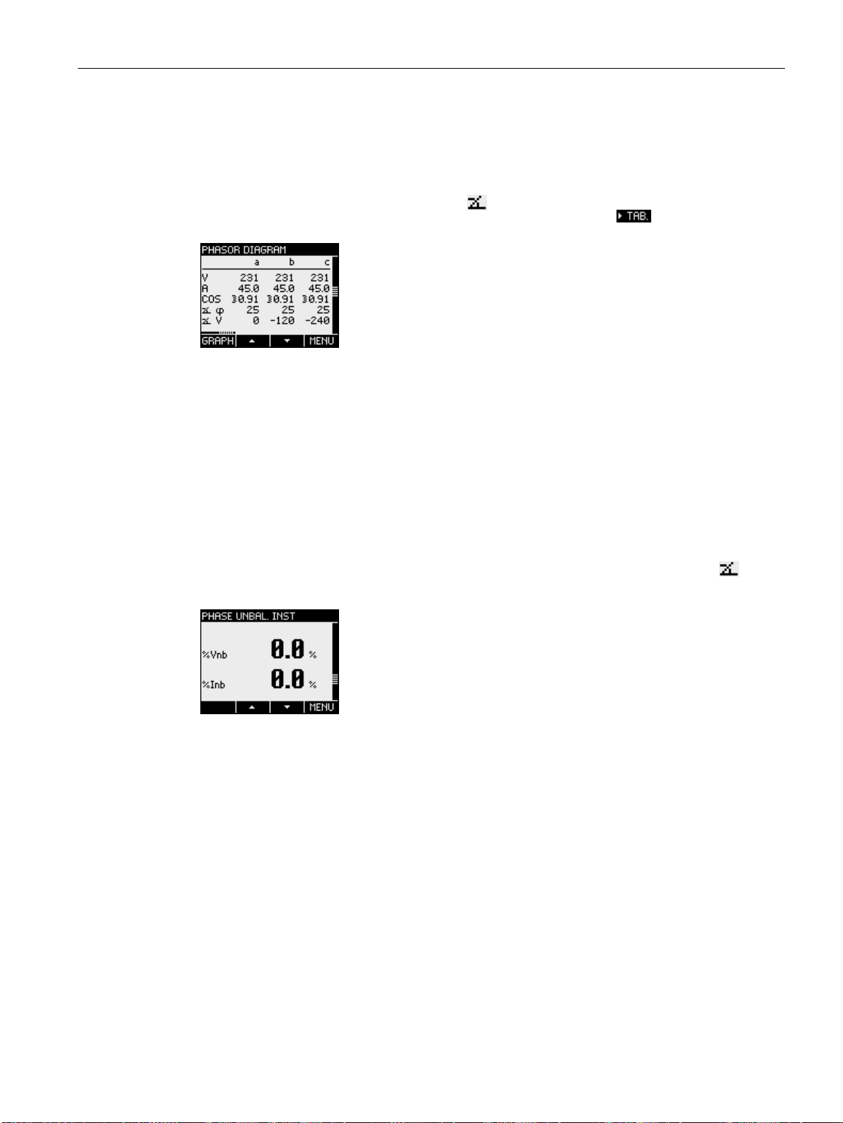
Description
3.7 Date and time
The display represents the instantaneous value of the phase angle on several screens:
● Phasor diagram,
can be called with "MAIN MENU" > "PHASOR DIAGRAM"
Unbalance
● Value table of the phasor diagram, row
can be called with "MAIN MENU" > "PHASOR DIAGRAM" > F1
Figure 3-10 Phasor diagram, value table
A three-phase system is referred to as balanced if the three phase-to-phase voltages and
phase-to-phase currents have an identical amplitude and are offset 120° from each other.
SENTRON PAC4200 calculates the unbalance for voltage and current according to the
EN 61000-4-27:2000 standard.
The display represents the unbalance information on several screens:
● "PHASE UNBAL.", current and voltage unbalance in percent
● PHASOR DIAGRAM, absolute values of the current, voltage, and phase angle "
each phase
V"
V" for
Figure 3-11 Voltage and current unbalance
In addition to the vectorial calculation of the phase unbalance, SENTRON PAC4200 also
supplies the amplitude unbalance for current and voltage according to the IEC 61557-12
standard at the communication interfaces. The amplitude unbalance only takes account of
the amplitude and not the phase angle.
3.7 Date and time
UTC time and local time
The internal clock of SENTRON PAC4200 measures UTC time. All information about the
date and time (time stamp) that can be called at the communication interfaces must be
interpreted as UTC time.
SENTRON PAC4200
System Manual, 09/2009, A5E02316180B-02
43
Page 44

Description
3.8 Limits
The SENTRON PAC4200 display indicates the configured local time corresponding to the
time difference due to time zones and daylight saving time.
UTC time: Universal Time Coordinated (UTC) is the international reference time.
Time zone: Geographical areas with the same positive or negative deviation from UTC time
are grouped together in time zones.
Local time: Local time is UTC time plus or minus the time difference due to the time zone
plus or minus the time difference due to the locally applicable daylight saving time.
Example: 3.36 p.m. CEST (local time in Germany) on September 10, 2008 corresponds to
1.36 p.m. (UTC time) on September 10, 2008. Germany is located in the UTC+1 time zone.
Daylight saving time applies on the above-mentioned date, so that the local time difference is
increased by one hour ("+1").
Synchronization of the internal clock
The internal clock of SENTRON PAC4200 can be synchronized with an external time, e.g.
with the "Top of minute" pulse or with a synchronization command via the available
communication interfaces.
Synchronization is relevant for all measured variables where the time of occurrence is also
captured, e.g. for recording the load profile.
3.8 Limits
SENTRON PAC4200 monitors up to 12 limit values as well as one limit that can be formed
by logically combining the other 12 limits.
Defining the limit values
The number of limit values to be monitored is selectable. The following must be specified for
each of the maximum of 12 limit values:
● Limit value monitoring ON/OFF
● Monitored measured variable
● Threshold
● Upper or lower limit violated
● Time delay
● Hysteresis
Combination of the limit values
The limit value formed by the logical combination is called "LIMIT LOGIC".
SENTRON PAC4200 provides parameterizable logic for combining the limit values that
supports brackets, takes account of priority rules, and allows logical negation.
The logic is represented on the display using the graphic symbols familiar from digital
technology: Four logic function blocks are connected upstream of one higher-level logic
function block. Each of the upstream logic function blocks has 4 usable inputs.
SENTRON PAC4200
44 System Manual, 09/2009, A5E02316180B-02
Page 45
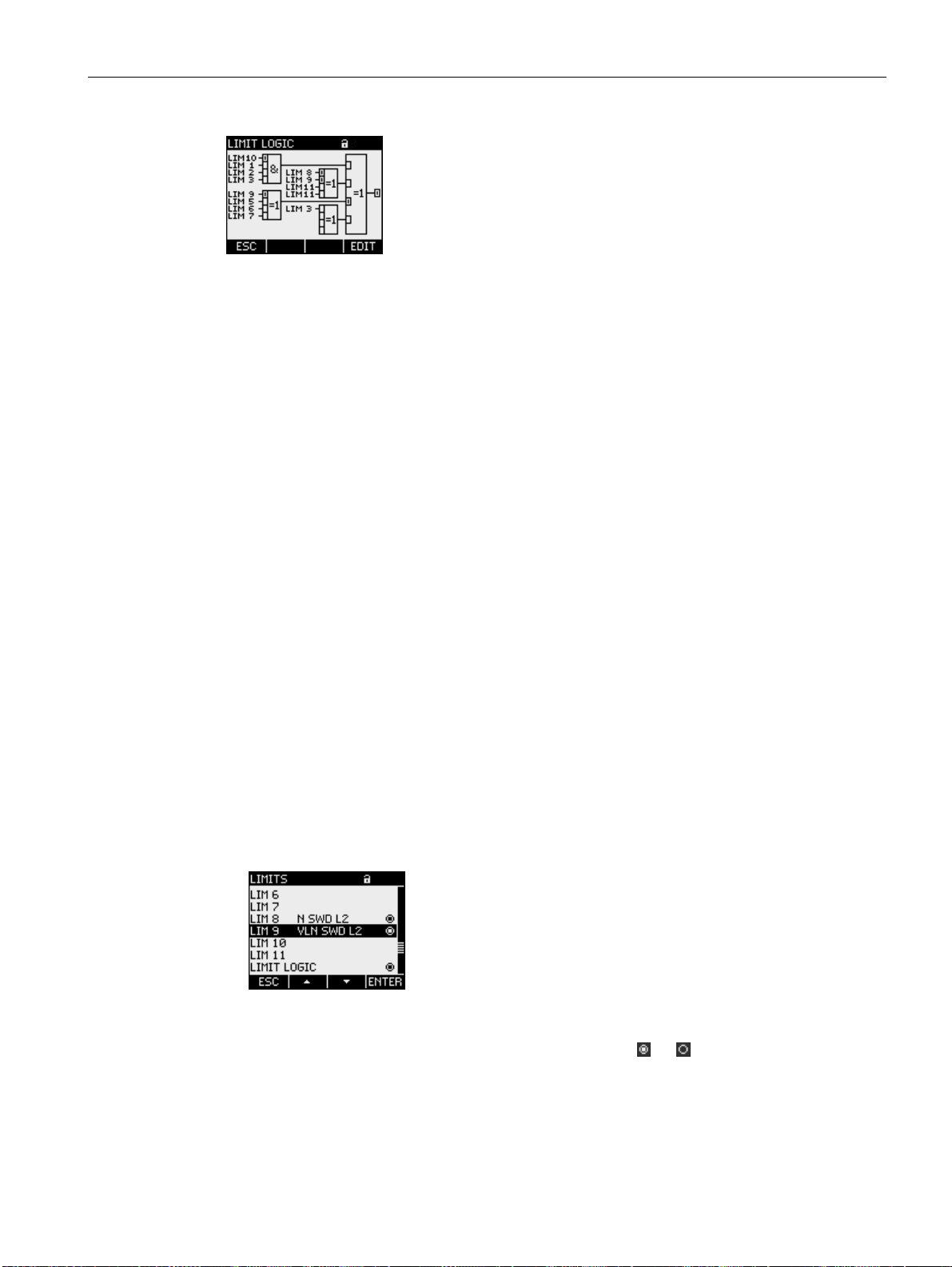
Description
3.8 Limits
Figure 3-12 LIMIT LOGIC
The following logic operations can be selected for each logic function block:
● AND (AND operation)
● NAND (NOT AND operation)
● OR (OR operation)
● NOR (NOT OR operation)
● XOR (EXCLUSIVE OR operation)
● XNOR (EXCLUSIVE NOT OR operation)
Any limit values and the digital inputs of SENTRON PAC4200 can be selected at the inputs
of the upstream logic function blocks. The input value is the truth value of the monitored
signal:
● True: Limit value is violated or input is active
● False: Limit value is not violated or input is not active
Displaying limit violations
SENTRON PAC4200 outputs limit violations at the digital output or via the interfaces.
Limit violations are countable. One of the limit values can be assigned to the universal
counters.
Limit violations are recorded as events with additional information on the monitored
measured variable and the monitored threshold.
Limit violations are shown on the following displays:
● MAIN MENU > SETTINGS > ADVANCED > LIMITS
● ... > LIMITS > LIMIT LOGIC
Left column: Limit value designation
Middle column: Monitored data source
Right column: Limit value currently violated: Yes
Figure 3-13 Representation of limit violations
, No
SENTRON PAC4200
System Manual, 09/2009, A5E02316180B-02
45
Page 46
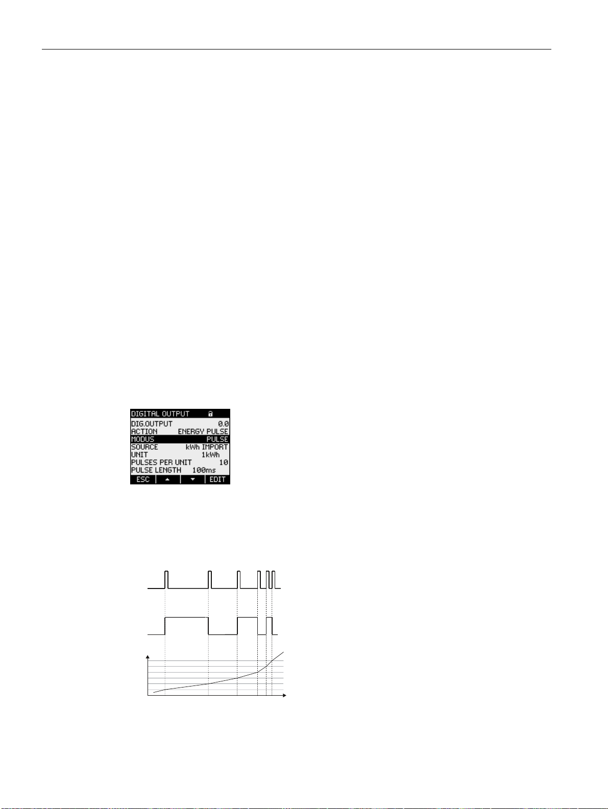
Description
3.9 Function of the digital inputs and outputs
3.9 Function of the digital inputs and outputs
SENTRON PAC4200 has:
● Two multifunctional integral digital inputs
● Two multifunctional integral digital outputs
● Optionally up to 8 plug-in digital inputs
● Optionally up to 4 plug-in digital outputs
Functions of the digital outputs
The following functions can be assigned to the digital outputs:
● Energy pulse output, programmable for active or reactive energy
● Signaling the direction of rotation
● Displaying the operating status of SENTRON PAC4200
● Signaling limit violations
● Switching output, remote controlled via the communication interfaces
● Output of the end of a subperiod for synchronizing other devices
Signal output
The digital output supplies a number of pulses or edges proportional to the energy
measured.
Figure 3-14 Digital output
The output of pulses or edges can be parameterized.
The rising and falling edges are counted.
38/6(
('*(
(
W
Figure 3-15 Types of count signal
SENTRON PAC4200
46 System Manual, 09/2009, A5E02316180B-02
Page 47

Description
3.9 Function of the digital inputs and outputs
The digital output is passive and implemented exclusively as a switch.
The implementation of the pulse shape corresponds to the IEC 62053-31 standard.
Pulse length, turn-off time
(1) Pulse length
(2) Turn-off time
Figure 3-16 Pulse length and turn-off time
● Pulse length:
Time for which the signal at the digital output is "high". The minimum pulse length is
30 ms and the maximum 500 ms.
● Turn-off time:
Time for which the signal at the digital output is "low". The turn-off time depends on the
measured energy, for example, and can be days or months.
● Minimum turn-off time:
The minimum turn-off time is specified by the programmed pulse length.
Functions of the digital inputs
The following functions can be assigned to the digital inputs:
● Tariff switching for on-peak and off-peak.
● Synchronization of the measuring period by means of the synchronization pulse of a
system control center or other device.
● Synchronization of the internal clock ("Top of minute").
● Status monitoring: Capturing statuses of connected signal encoders.
● Energy signal for active or reactive energy or freely definable energy types.
● Starting and stopping the process energy counters and the process operating hours
counter
● Copying and resetting:
– All process energy counters
– The counter for process active energy
– The counter for process reactive energy
– The counter for process apparent energy
SENTRON PAC4200
System Manual, 09/2009, A5E02316180B-02
47
Page 48

Description
3.10 Ethernet port
● Resetting:
– The process energy counters and the process operating hours counter
– The counter for process active energy
– The counter for process reactive energy
– The counter for process apparent energy
– All process energy counters, the process operating hours counter and all pulse
counters
– A specific pulse counter
A maximum voltage of 30 V can be applied to the digital input. Higher voltages require an
external voltage divider.
Signal input
Either edge or pulse counting.
Data is transferred with the help of weighted pulses or edges, e.g. a parameterizable number
of pulses or edges is transferred per kWh.
The countable unit can be defined separately for each application.
The implementation of the pulse shape corresponds to the IEC 62053-31 standard.
3.10 Ethernet port
SENTRON PAC4200 is equipped with an Ethernet interface. This interface facilitates:
● Configuration of the device using the SENTRON powerconfig software
● Communication between the device and the energy management system
● Device firmware updates
SENTRON PAC4200
48 System Manual, 09/2009, A5E02316180B-02
Page 49

Description
3.11 Slots for expansion modules
Properties of the Ethernet interface
● Transmission rate 10 / 100 Mbit/s
● RJ45 socket (8P8C) on the top of the device for RJ45 connector with EIA/TIA T568B
assignment
● Cable type 100Base-TX (CAT5)
The Ethernet cable must be grounded for data transmission according to the Fast
Ethernet standard. You can find information on grounding in the "Connecting" chapter.
● Autonegotiation
● MDI-X auto crossover
● Communication over MODBUS TCP
NOTICE
Interference with other network nodes due to incorrect network settings
Incorrect network settings can adversely affect or interfere with the functions of other
network nodes The network settings for Ethernet are defined by the system
administrator and must be set accordingly on the device.
If the settings are not known, the (patch) cable must not be connected.
Autonegotiation is a method used by network communication peers to automatically
negotiate the highest possible transmission rate. SENTRON PAC4200 is automatically set to
the transmission rate of the communication peer if the latter does not support
autonegotiation.
MDI-X auto crossover describes the ability of the interface to autonomously detect the send
and receive lines of the connected device and adjust to them. This prevents malfunctions
resulting from mismatching send and receive wires. Both crossed and uncrossed cables can
be used.
3.11 Slots for expansion modules
Interface
SENTRON PAC4200 has two slots (MOD1 and MOD2) for installing optionally available
expansion modules.
Please consult the current catalogs to find out which modules are available for
SENTRON PAC4200.
One expansion module can be operated alone on the device or two expansion modules
simultaneously.
SENTRON PAC4200
System Manual, 09/2009, A5E02316180B-02
49
Page 50
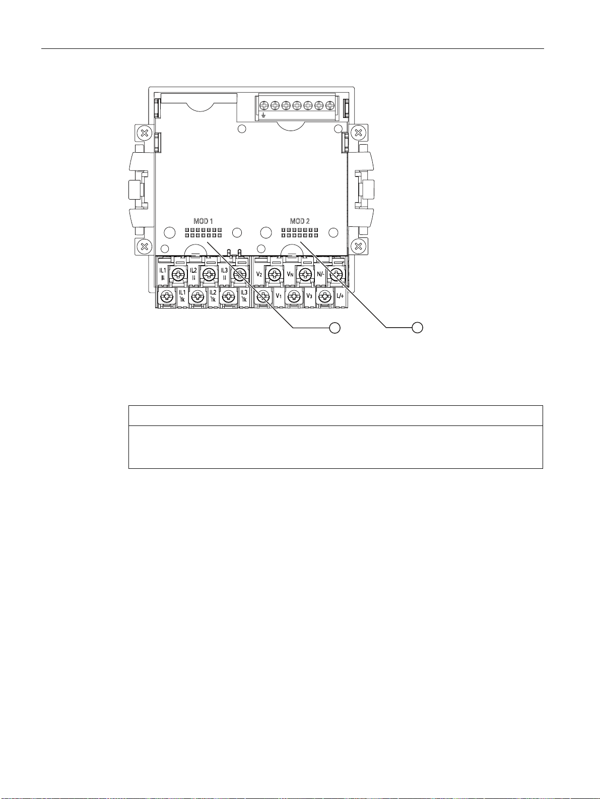
Description
3.12 Gateway
DIC DI0DI1 DOC DO0DO1
(1) MOD1 slot
(2) MOD2 slot
Figure 3-17 SENTRON PAC4200, rear
CAUTION
Avoid contamination of the contact areas below the labels "MOD1" and "MOD2", since
otherwise the expansion modules cannot be connected or can even be damaged. Insertion
of metal pins or wires into the contact openings can result in device failure.
3.12 Gateway
SENTRON PAC4200 can be used as a gateway. This allows devices (slaves) that are
connected to the RS485 expansion module of PAC4200 to be connected to a device over
Ethernet (master).
Operating principle
Data sent by the master to the addressed target device: The higher-level software packages
the serial protocol into TCP/IP packets. SENTRON PAC4200 unpacks the TCP/IP packets
and forwards the freed packets of the serial protocol to the serial port (RS485).
Data sent by the addressed target device to the master: SENTRON PAC4200 packages the
serial protocol packets into the TCP protocol and forwards the packaged user data to the
higher-level software.
SENTRON PAC4200
50 System Manual, 09/2009, A5E02316180B-02
Page 51
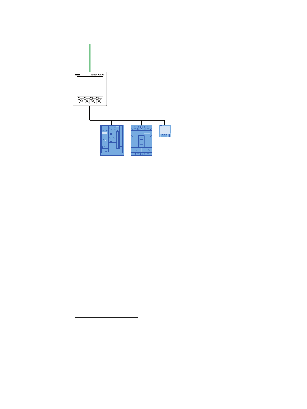
Description
3.12 Gateway
(WKHUQHW
7&3,3
6(175213$&
56
Figure 3-18 SENTRON PAC4200 as a gateway
Requirements and conditions
The SENTRON PAC RS485 expansion module is required to connect the RS485 bus.
According to the RS485 bus specification, up to 31 devices can be addressed via the
gateway without special RS485 repeaters.
The higher-level software must support the serial protocol of the addressed target device as
well as packaging/unpacking the serial protocol into/from TCP/IP.
SENTRON PAC RS485 expansion module
The slot for the SENTRON PAC RS485 expansion module is freely selectable.
Configuration of the gateway
SENTRON PAC4200 must be configured for using the gateway.
● Start up the SENTRON PAC RS485 expansion module on the SENTRON PAC4200.
● Set the communication parameters for operating the RS485 bus below the gateway.
These settings are possible on the display of SENTRON PAC4200 or in the software.
You can find information about parameterizing RS 485 in the documentation for the
SENTRON PAC RS485 expansion module or under Modbus-IDA
http://www.Modbus-IDA.org).
(
SENTRON PAC4200
System Manual, 09/2009, A5E02316180B-02
51
Page 52

Description
3.13 Slots
Addressing the target devices
The following address information is required in the software in order to address a device via
the gateway of SENTRON PAC4200:
● IP address of SENTRON PAC4200
● Gateway port
– Port 17002 if the RS485 bus is connected to the "MOD1" slot
– Port 17003 if the RS485 bus is connected to the "MOD2" slot
● Bus address of the target device, e.g. MODBUS address
Further information
You will find further information at:
Modbus.org "MODBUS MESSAGING ON TCP/IP IMPLEMENTATION GUIDE".
See also
Modbus IDA (http://www.Modbus-IDA.org)
3.13 Slots
Battery compartment
The battery compartment of the SENTRON PAC4200 is accessible from the outside without
opening the housing.
SENTRON PAC4200
52 System Manual, 09/2009, A5E02316180B-02
Page 53
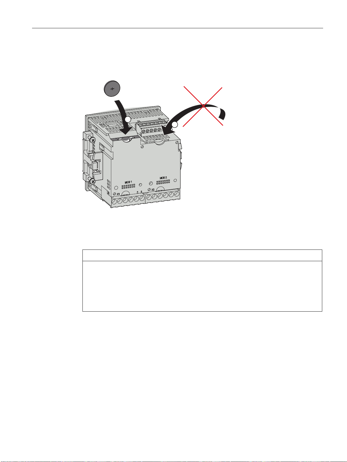
Description
3.13 Slots
Slot for memory card
The card slot of the SENTRON PAC4200 has no function. The device does not contain a
card reader.
(1) Battery compartment
(2) Non-functional card slot opening
Figure 3-19 Insertion openings of the SENTRON PAC4200
CAUTION
Foreign body in the unit can trigger a short-circuit
The battery compartment is intended exclusively for holding the battery. Foreign bodies
introduced into the unit via the battery compartment or via the insertion opening of the card
slot can cause a short-circuit and damage the device. It is not possible to retrieve any
foreign bodies once inserted.
Do not insert any foreign bodies into the device.
See also
Replacing the battery (Page 170)
SENTRON PAC4200
System Manual, 09/2009, A5E02316180B-02
53
Page 54

Description
3.14 Password protection
3.14 Password protection
SENTRON PAC4200 can be protected with a password.
Scope
The password protection is activated for write accesses via the user interface or via the
integrated Ethernet interface.
Format
A four-digit, numeric password is used.
Default
The default password is: 0000
See also
Password management (Page 159)
Advanced (Page 151)
3.15 User-definable displays
Up to four measurements can be individually configured for SENTRON PAC4200. Four
presentational formats can be selected:
● Digital display of two measured variables
● Digital display of four measured variables
● Bar diagram for measured variables
● Bar diagram for three measured variables
● User-definable displays of counters in conjunction with the SENTRON PAC 4DI/2DO
expansion module
SENTRON PAC4200
54 System Manual, 09/2009, A5E02316180B-02
Page 55
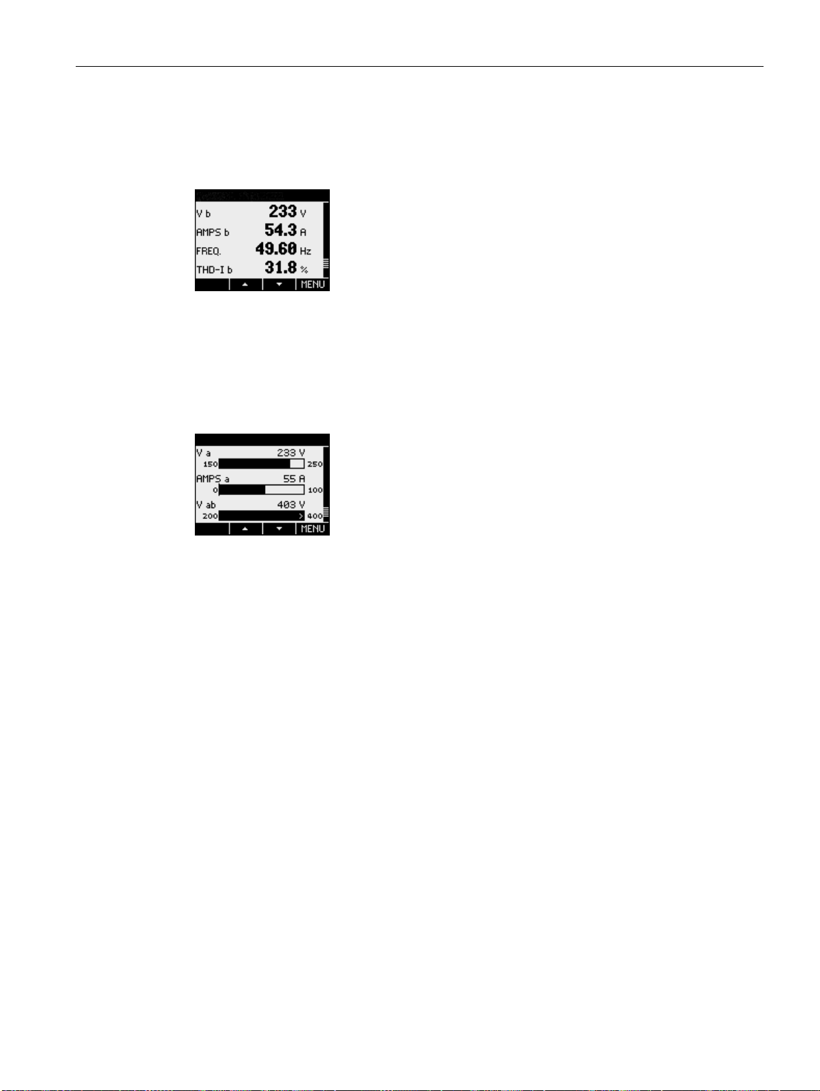
Description
3.16 Events
Digital display
The instantaneous value, the designation, and the unit are shown for each measured
variable.
Figure 3-20 Example of a definable display (digital display)
Graphical display
The instantaneous value, designation, unit, and parameterizable value range are shown for
each measured variable. The instantaneous value is represented as a bar diagram and
digital information.
Figure 3-21 Example of a freely definable display (bar diagram)
An outward pointing arrow in the bar means that the instantaneous value displayed is
outside the parameterized range.
Displays for counters
Users can define up to 5 displays in conjunction with the SENTRON PAC 4DI/2DO
expansion module.
Configuring
The displays can be configured with the SENTRON powerconfig software.
3.16 Events
The device reports the occurrence of certain events. These events are listed in the event
recording undertaken by SENTRON PAC. You can acknowledge acknowledgable events in
a popup window on the device.
SENTRON PAC4200
System Manual, 09/2009, A5E02316180B-02
55
Page 56
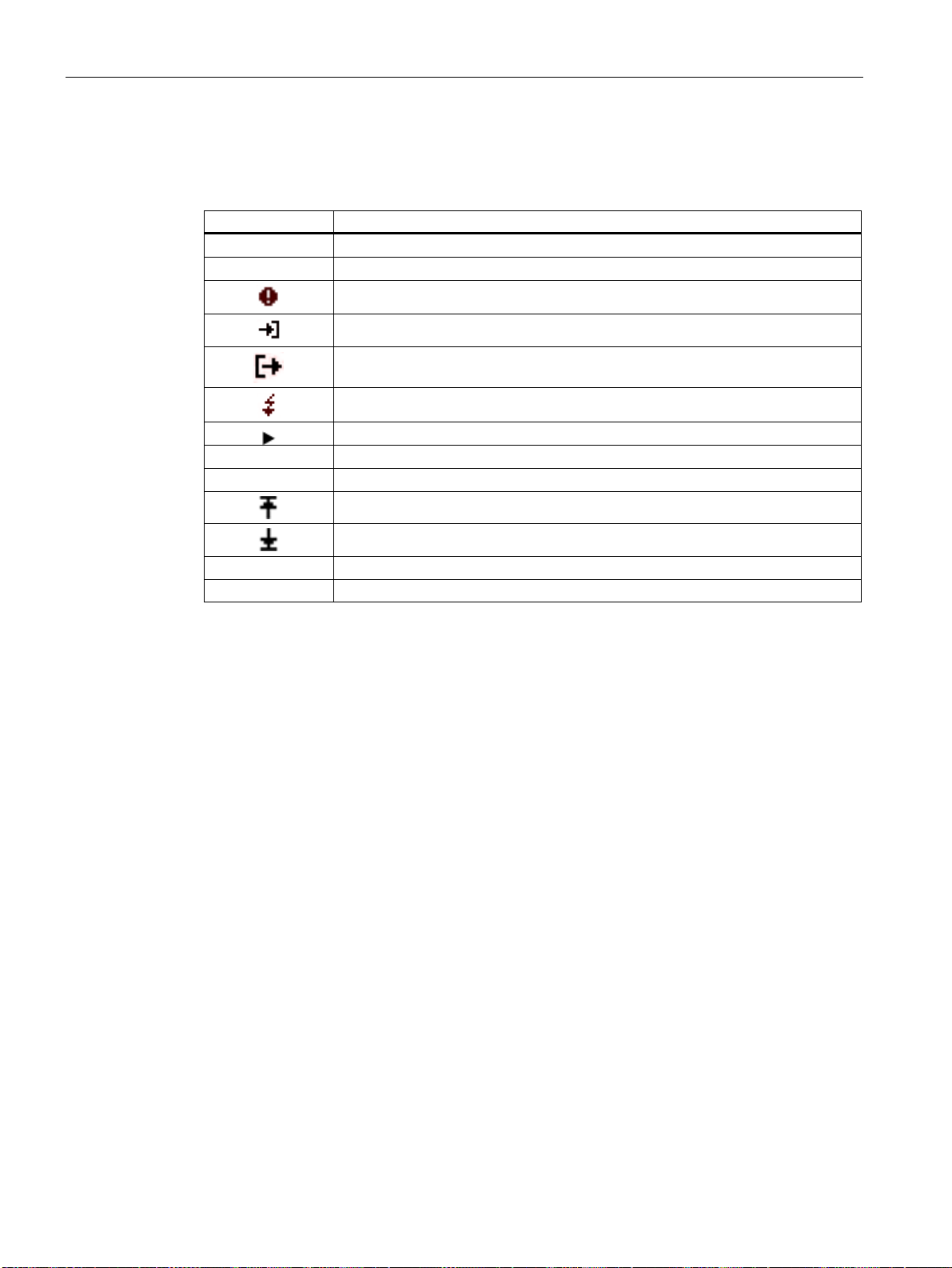
Description
3.16 Events
Displaying events
Table 3- 4 Meaning of the symbols in the events list
Symbol Meaning
No symbol Information
! Warning
Q Acknowledged event
# Interrupt, error, missing
...= 0 Reset
...= 1 Condition met
Alarm
Incoming event
Outgoing event
Overcurrent, overvoltage
Changed
Upper limit violated, out of range
Lower limit violated
The events are divided into the following event classes:
● Operating information
● System information
● Operation
The following information is shown for each event:
● Event
● Event class
● Date and time when the event occurred
● Reason why the event occurred
● Interface (if applicable)
● Measured value affected and corresponding measurement (if applicable)
● Limit value (if applicable)
● Address of the digital output (if applicable)
● Address of the digital input (if applicable)
SENTRON PAC4200
56 System Manual, 09/2009, A5E02316180B-02
Page 57
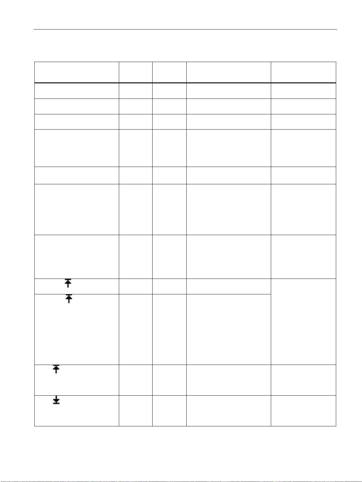
Description
3.16 Events
Table 3- 5 The following events are reported:
Event Event
class
START PMD System
information
PMD INFO System
information
COMM.FAULT System
information
FW UPDATE # System
information
TIME CORR: System
information
TIME SYNC # System
information
VOLTAGE # Operating
information
VOLTAGE Operating
information
CURRENT Operating
information
LIMIT Operating
information
LIMIT Operating
information
Standard
warning
level
Information Voltage recovery -
Warning PMD information Please contact Support.
Warning A communications fault has
Warning Transmission error:
Information Top of minute:
Information The time synchronization has
Warning The supply voltage has been
Alarm The voltage is out of range
Alarm The current is out of range.
Information The upper limit value xxxx has
Information The lower limit value xxxx has
Reason Remedy
Check the network
occurred at the slot xx interface.
The firmware is not suitable.
The time has been corrected.
failed.
Interface: Slot xx
interrupted.
Measured variable x
Measured variable x
Measured variable x
been exceeded.
Measured variable x, limit
value xxxx
been exceeded.
Measured variable x, limit
value xxxx
settings
Make sure you are using
the correct firmware
version for the update.
Restart the firmware
update.
The "Top of minute"
pulses for synchronizing
the time are not active.
Check the hardware and
the settings for
transmitting the "Top of
minute" pulses.
The device has been
disconnected from the
network in accordance
with the schedule.
An error has occurred.
Check the power supply.
Danger of serious or
fatal injury or of serious
damage to the device.
Make sure the system is
operating under
conditions for which
SENTRON PAC is
approved.
It is possible that the
measurements are not
correctly displayed.
Please contact Support.
-
-
-
SENTRON PAC4200
System Manual, 09/2009, A5E02316180B-02
57
Page 58
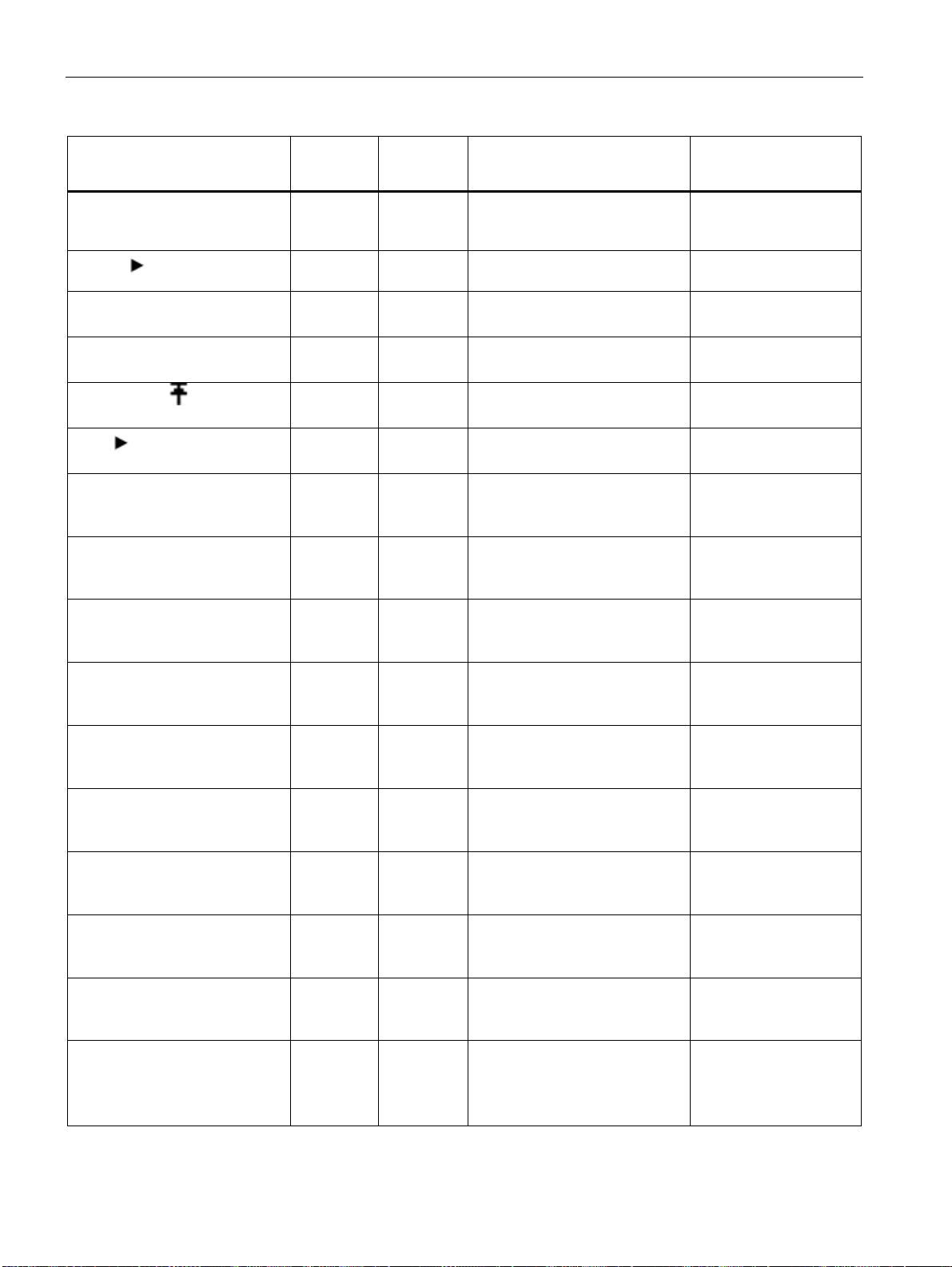
Description
3.16 Events
Event Event
class
LIMIT LOG. OP=1 Operating
information
TARIFF Operating
information
STATUS DI Operating
information
STATUS DO Operating
information
PULSE FREQ Operating
information
TIME Operating
information
FACT. DEFAULTS Operating
information
BASIC PARAM Control Warning The basic configuration has
SETTING Control Warning The configuration has been
COMM. Control Information The communication
MAX/MIN=0 Control Information The maximum / minimum values
OP.HOURS=0 Control Information The operating hours counter has
D ENERGY=0 Control Information The day energy counter has
EVENT=0 Control Information The event recordings have been
LOAD REC.=0 Control Information The load profile recording has
ENERGY C.=0 Control Information All energy counters have been
Standard
warning
level
Information The limit logic operation
Information Tariff change to ... -
Information The digital input is activated.
Information The digital output is activated.
Information The pulse frequency is too high.
Information The time was set on:
Information The factory defaults have been
Reason Remedy
complies with the limit
value xxxx.
DI address xx.xx
DO address xx.xx
DO address xx.xx
Slot xx interface
set.
Slot xx interface
been changed.
Slot xx interface
changed.
Slot xx interface
configuration has been changed.
Slot xx interface
have been reset.
Slot xx interface
been reset.
Slot xx interface
been reset.
Slot xx interface
deleted.
Slot xx interface
been deleted.
Slot xx interface
reset.
Value 00000000
Slot xx interface
-
-
-
-
-
-
-
-
-
-
-
-
-
-
-
SENTRON PAC4200
58 System Manual, 09/2009, A5E02316180B-02
Page 59

Description
3.16 Events
Event Event
class
UNIV.=0 Control Information The universal counters have
PASSWORD Control Information Password protection is activated.
PASSWORD Control Information The password has been
FIRMWARE Control Information The firmware has been updated.
1) Counter = active energy import tariff 1 / 2 kWh, reactive energy export tariff 1 / 2 kVAh, apparent energy tariff 1 / 2 kVAh
Standard
warning
level
Reason Remedy
-
been reset.
Value 00000000
Slot xx interface
-
Slot xx interface
changed
Slot xx interface
Version PAC4200 Vx.xx
Slot xx interface
Acknowledging an event
If an event is set to "acknowledgable" in the software, a popup window for this event opens
on the device. Acknowledge the event in the popup window with "OK". Acknowledgment
closes the popup window. The event is logged in the event memory.
Settings in the SENTRON software
You can make the following settings in the software:
● Change the warning level for an event
● Acknowledge an event
● Entry of an event in the event memory
● Output of the event at the digital output
● Order of appearance on the display
See also
Safety notes (Page 17)
SENTRON PAC4200
System Manual, 09/2009, A5E02316180B-02
59
Page 60

Description
3.17 Performance features of the PAC PROFIBUS DP expansion module
3.17 Performance features of the PAC PROFIBUS DP expansion module
You can use the PAC PROFIBUS DP expansion module to access the SENTRON PAC
Power Monitoring Devices during operation.
Overview
Features include:
● Communication based on the PROFIBUS DP master-slave principle:
The PAC PROFIBUS DP expansion module provides the PROFIBUS DP master with
measured values of the SENTRON PAC Power Monitoring Device. It receives
information, e.g. commands, from the PROFIBUS DP master, and forwards this
information to the SENTRON PAC Power Monitoring Device.
● Function: PROFIBUS DP slave
● Communication with the class 1 master and the class 2 masters
● Cyclic data transfer
● Acyclic data transfer
● Specific GSD file for every Power Monitoring Device type. This allows correct integration
into the controller.
● Automatic detection of the baud rate
● Clock synchronization depending on the device type
● Setting the PROFIBUS address:
– At the device
– With parameterization software
– Per PROFIBUS
● Generation of diagnostic interrupts and process interrupts
● Diagnostics also via the local display
● Status display via LED
● To ensure galvanic isolation between the SENTRON PAC Power Monitoring Device and
the PROFIBUS.
You can find further information on the PAC PROFIBUS DP expansion module in:
● the manual "SENTRON PAC PROFIBUS DP Expansion Module"
● the operating instructions "SENTRON PAC PROFIBUS DP Expansion Module"
SENTRON PAC4200
60 System Manual, 09/2009, A5E02316180B-02
Page 61

Description
3.18 Performance features of the PAC RS485 expansion module
3.18 Performance features of the PAC RS485 expansion module
You can integrate the SENTRON PAC into RS 485 systems with the help of the PAC RS485
expansion module.
Overview
Features include:
● Communication based on the master-slave principle via the serial interface
● Function:
– Modbus RTU slave
– Serial gateway
– Modbus gateway (MB gateway)
● Configuration via:
– the SENTRON PAC Power Monitoring Device
–
SENTRON powerconfig
● Unicast messages
● Broadcast commands with address 0 to the MODBUS slaves
3.19 Performance features of the SENTRON PAC 4DI/2DO expansion module
You expand the digital inputs and digital outputs with the SENTRON PAC 4DI/2DO
expansion module.
Overview
● Plug-in expansion module for the SENTRON PAC devices
● Does not require an external power supply
● Configuration via:
– the SENTRON PAC Power Monitoring Device
–
SENTRON powerconfig
● Connected using screw terminals
● Four digital inputs with:
– Functions as on the SENTRON PAC
– Active input circuit. This enables optional connection without external power supply.
● Two digital outputs with:
– Functions as on the SENTRON PAC
SENTRON PAC4200
System Manual, 09/2009, A5E02316180B-02
61
Page 62

Description
3.19 Performance features of the SENTRON PAC 4DI/2DO expansion module
SENTRON PAC4200
62 System Manual, 09/2009, A5E02316180B-02
Page 63
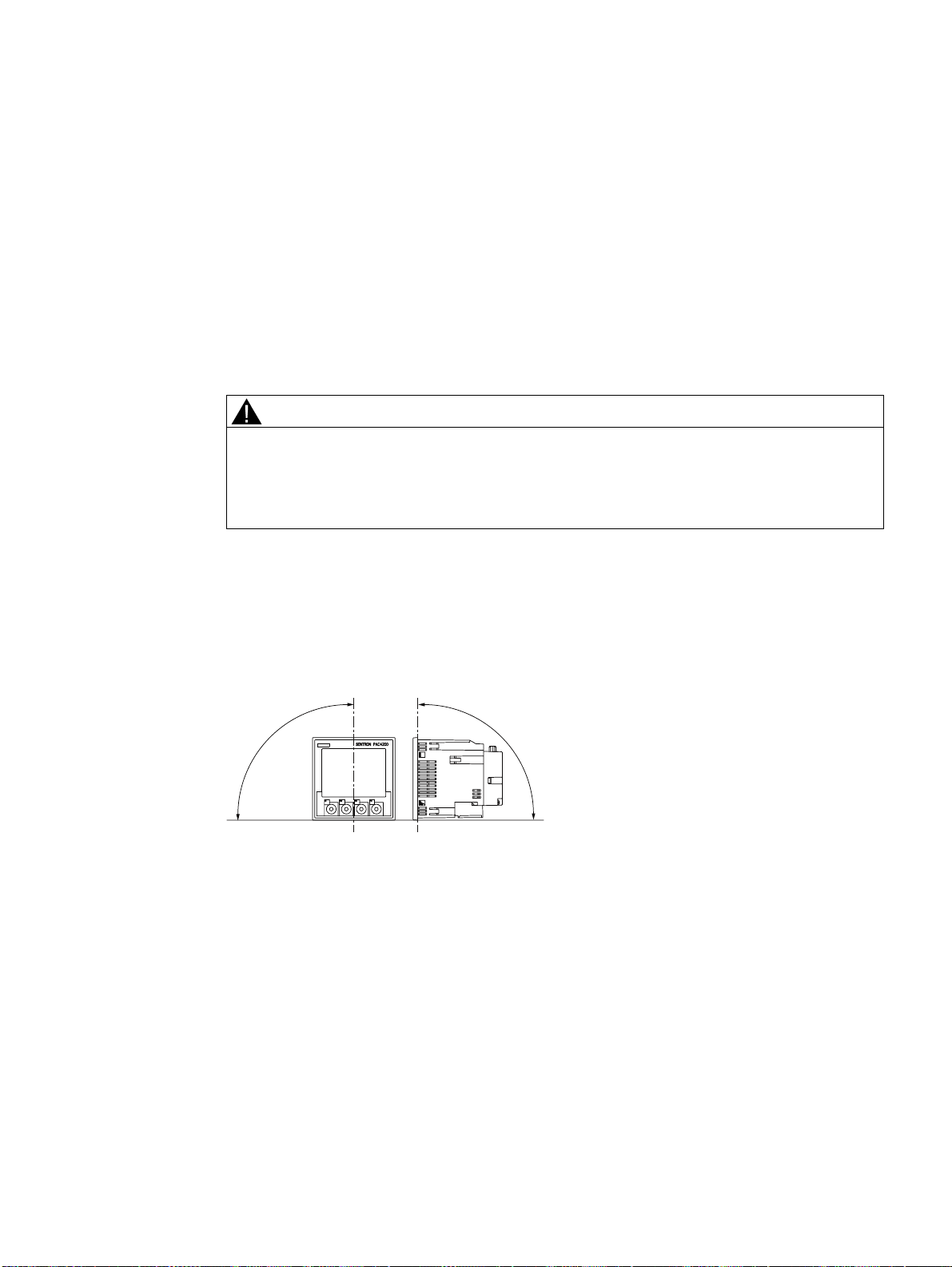
Operation planning
4.1 Operation planning
Mounting location
The SENTRON PAC4200 device is intended for installation in permanently installed
switching panels within closed rooms.
WARNING
Only operate the device in a secure location.
Can cause death, serious injury or considerable property damage.
SENTRON PAC should only be operated in a lockable control cabinet or a lockable room.
Ensure only qualified personnel have access to this cabinet or room.
Conductive panels and doors on control cabinets must be grounded. The doors of the control
cabinet must be connected to the control cabinet using a grounding cable.
4
Mounting position
The device must be installed vertically.
r
s
Figure 4-1 Mounting position
The preferred direction of viewing is from below at an angle.
r
SENTRON PAC4200
System Manual, 09/2009, A5E02316180B-02
63
Page 64

Operation planning
4.1 Operation planning
Installation space and ventilation
Sufficient clearance must be maintained between the device and neighboring components in
order to comply with the permissible operating temperature. You can find dimension
specifications in the "Dimension drawings" chapter.
Plan additional space for:
● Ventilation
● Wiring
● RJ45 plug connector and cable feed on the top of the device
● Optionally connectable expansion modules on the rear of the device, including connector
and cable feed
CAUTION
Ensure ventilation
Insufficient ventilation may result in damage to the components. Please ensure that the
ventilation slots of the housing are not obstructed. The wiring, cable feed or other
components must not obstruct ventilation.
NOTICE
Damage due to moisture
Moisture or wetness can affect the operating capability of the components. Do not
operate the components in an environment affected by high humidity or wetness. Note
the environmental requirements of the SENTRON PAC Power Monitoring Device.
Environmental conditions
Use the SENTRON PAC4200 device only where environmental conditions permit its
operation:
Temperature range
Operating temperature - 10 °C through + 55 °C
Storage and transport temperature - 25 °C through + 70 °C
Relative humidity 95% at 25°C without condensation (normal
conditions)
Site altitude above sea level max. 2000 m
Degree of pollution 2
Degree of protection according to IEC 60529
Device front IP65
Type 5 enclosure acc. to UL50
Device rear
Device with screw terminal IP20
Device with ring lug terminal IP10
SENTRON PAC4200
64 System Manual, 09/2009, A5E02316180B-02
Page 65

Operation planning
4.1 Operation planning
Circuit breaker
A suitable circuit breaker must be connected upstream of SENTRON PAC4200 in order to
permit disconnection of the device from the power supply.
● The circuit breaker must be mounted close to the device and be easily accessible to the
user.
● The circuit breaker must be marked as the circuit breaker for the device.
Temperature compensation
To avoid condensation, the device must be stored at the operating location for at least 2
hours before power is connected.
See also
Dimension drawings (Page 193)
SENTRON PAC4200
System Manual, 09/2009, A5E02316180B-02
65
Page 66

Operation planning
4.1 Operation planning
SENTRON PAC4200
66 System Manual, 09/2009, A5E02316180B-02
Page 67
Installation
5.1 Unpacking
Observe the ESD Guidelines. Open the packaging carefully. Do not use excessive force.
Check the packaging
Carry out the following checks after receipt of the device and before installation:
● Ensure the packaging is undamaged.
● Make sure that the contents of the package are complete.
● Check the device for external damage.
Please contact your Siemens sales partner in the following cases:
● The packaging is damaged
● The contents of the package are not complete
● The device is damaged.
Do not install or start up damaged devices.
Damaged devices may result in death, serious injury, or property damage.
5
WARNING
Storage
SENTRON PAC4200
System Manual, 09/2009, A5E02316180B-02
Store the components in a dry place.
NOTICE
Avoid condensation
Sudden fluctuations in temperature can lead to condensation. Condensation can affect the
function of the device. Store the device in the operating room for at least 2 hours before
commencing installation.
67
Page 68

Installation
5.2 Insert battery
5.2 Insert battery
DANGER
Hazardous Voltage
Will cause death or serious injury.
Turn off and lock out all power supplying this device before working on this device.
For first start-up, use the battery supplied with the device. If you use another battery, this
must meet the requirements listed in the chapter "Technical data".
Procedure
NOTICE
Use only batteries tested in accordance with UL1642.
1. Discharge any static from your body. Observe the ESD guidelines in the Appendix.
CAUTION
Electrostatic sensitive devices
Discharge your body of any static electricity. Touch the grounded control cabinet, for
example, or a metal part that is connected to the building ground (heater, steel support).
2. Remove the battery from the SENTRON PAC4200 delivery carton.
NOTICE
Reduced service life of the battery
Grease or dirt on the contacts forms a transfer resistance that reduces the service life of
the battery.
Hold the battery by the edges only.
3. Take note of the polarity indicated at the insertion opening of the battery compartment.
Insert the battery into the battery compartment.
Note
Polarity of the battery
The opening of the battery compartment has the same shape as the battery. This
determines the alignment of the terminals. It is not possible to insert the battery
incorrectly.
SENTRON PAC4200
68 System Manual, 09/2009, A5E02316180B-02
Page 69
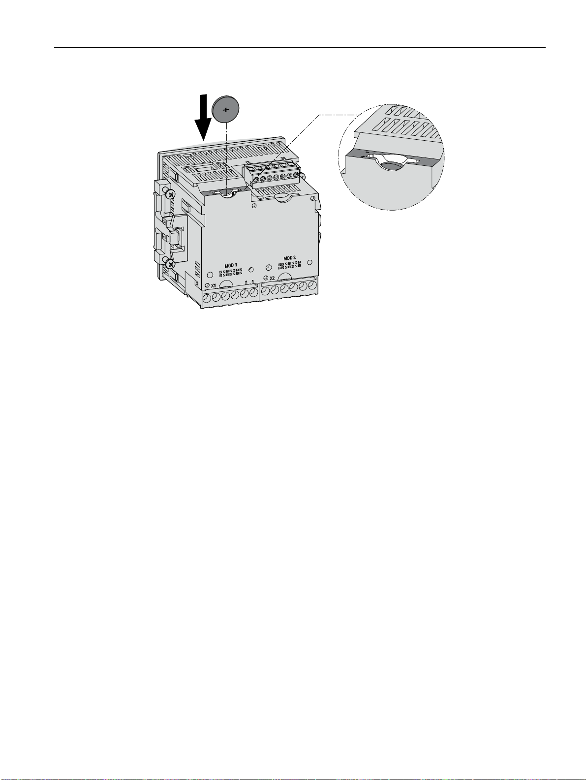
Installation
5.3 Tools
Figure 5-1 Using the battery
See also
Technical data (Page 175)
Electrostatic sensitive devices (ESD) (Page 273)
5.3 Tools
You require the following tools for installation:
● Cutting tool for the panel cutout
● Screwdriver PH2 cal. ISO 6789
Tools for installing the expansion modules
● Cross-tip screwdriver PZ1, ∅ 2.9 mm, 0.5 Nm cal. ISO 6789, also for assembling cables
on the terminal block of the PAC RS485 expansion module
● Crimping tool in accordance with EN 60947-1 for assembling cables with core end
sleeves on the terminal blocks
● Slotted screwdriver SZS 0.4x2.5 cal. ISO 6789 for assembling cables on the terminal
block of the SENTRON PAC 4DI/2DO expansion module
Additional installation tools
● Cable clamp for strain relief on all communication cables if used on the device.
SENTRON PAC4200
System Manual, 09/2009, A5E02316180B-02
69
Page 70

Installation
5.4 Mounting on the switching panel
5.4 Mounting on the switching panel
5.4.1 Mounting dimensions
Mounting and clearance dimensions
You can find information on the cutout dimensions, frame dimensions and clearances in the
Chapter "Dimension drawings".
See also
Dimension drawings (Page 193)
5.4.2 Installation steps
Procedure
Proceed as follows to install the SENTRON PAC4200 in the switching panel:
1. Cut a hole in the panel measuring 92.0
+0.8
x 92.0
+0.8
mm2 (if not already available).
2. Discharge any static from your body. Observe the ESD guidelines in the Appendix.
CAUTION
Electrostatic sensitive devices
Discharge your body of any static electricity. Touch the grounded control cabinet, for
example, or a metal part that is connected to the building ground (heater, steel support).
3. Insert the device into the cutout from outside (Fig. "Installation cutout A").
4. Carry out all other installation steps from the inside of the switching panel.
5. Clamp the device to the switching panel with the two brackets provided (Fig. "Installation
step B"). To do this, proceed as follows:
– Hold the device firmly in position with one hand.
– Hang the brackets onto the left and right sides of the housing.
To do so, insert the lugs of the bracket (2) into the slots on the housing (1).
– Tighten the locking hook. To do so, place the index finger and middle finger on the
supports as shown in the figure "Installation step C". Insert the locking hook with the
thumb.
The locking mechanism of both supports enables you to secure the device in the
switching panel quickly and without tools. The front of the switching panel is fully sealed
with the standard, integrally extruded seal. To achieve degree of protection IP65, the four
screws in the supports must be additionally tightened.
SENTRON PAC4200
70 System Manual, 09/2009, A5E02316180B-02
Page 71
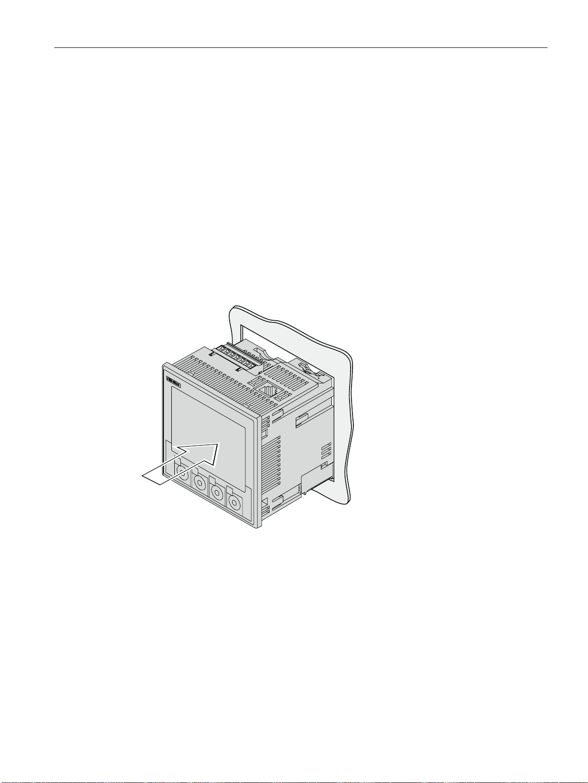
Installation
5.4 Mounting on the switching panel
6. Tighten the 4 screws evenly in the two brackets; tightening torque 0.3 Nm (Fig.
"Installation step D").
7. When using the Ethernet interface:
– Refer to the information about cable quality and connector design in the chapter
"Technical data".
– Ground the shielding of the Ethernet cable at both ends of the cable. Refer to the
"Connecting" chapter for more information.
– Ensure strain relief for the RJ45 connector.
Secure the Ethernet cable to the panel for this purpose. Fix the cable in position as
shown in the figure "Installation step E" at location (3) using a self-adhesive cable
clamp or other suitable small installation accessory.
8. When using optional expansion modules:
– insert the expansion module into the slots on the rear of the device. You can find the
installation instructions in the operating instructions of the relevant expansion module.
Installation is complete.
Figure 5-2 Installation step A, device with screw terminals
SENTRON PAC4200
System Manual, 09/2009, A5E02316180B-02
71
Page 72
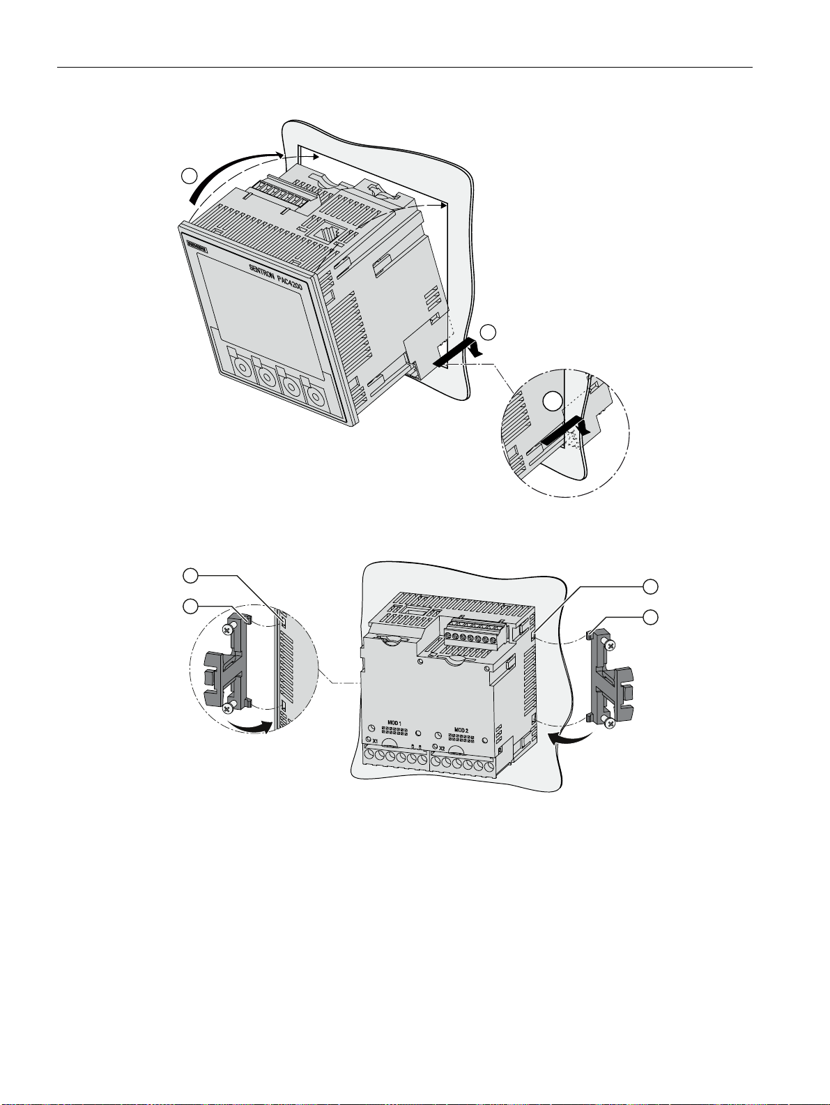
Installation
5.4 Mounting on the switching panel
Figure 5-3 Installation step A, device with ring lug terminals
Installation step B
SENTRON PAC4200
72 System Manual, 09/2009, A5E02316180B-02
Page 73
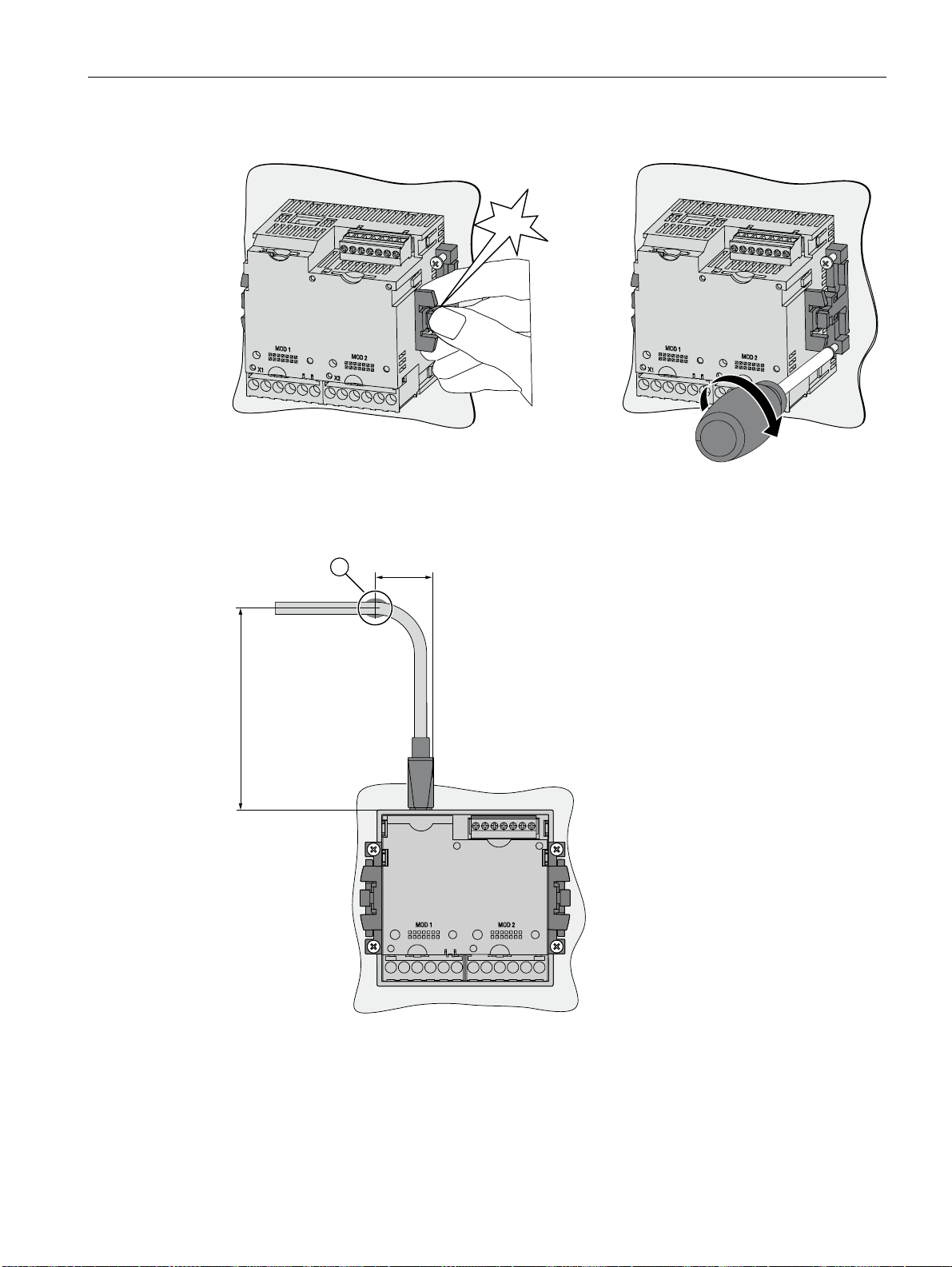
Installation
5.4 Mounting on the switching panel
&OLFN
Installation step C
Installation step D
Figure 5-4 Installation step E, strain relief for RJ45 connector
SENTRON PAC4200
System Manual, 09/2009, A5E02316180B-02
73
Page 74

Installation
5.5 Installing the expansion modules
NOTICE
Do not cover the ventilation slots!
If the ventilation slots are covered, the components can overheat. Make sure that the
ventilation slots are not covered.
NOTICE
Ensure that no tools or other potentially hazardous objects have been left at the installation
location.
See also
Grounding of the Ethernet cable (Page 94)
Technical data (Page 175)
Electrostatic sensitive devices (ESD) (Page 273)
5.5 Installing the expansion modules
Assembly
Install the expansion module before starting up the SENTRON PAC. Observe the ESD
Guidelines.
CAUTION
Defective connector to SENTRON PAC Power Monitoring Device
Dirty or bent pins can affect the function of the connectors. The connectors can be
destroyed. Do not allow the pins to become dirty.
Make sure that:
• There are no metal parts between the pins.
• There are no metal parts adhering to the pins.
• The pins do not bend.
Do not touch the pins.
SENTRON PAC4200
74 System Manual, 09/2009, A5E02316180B-02
Page 75
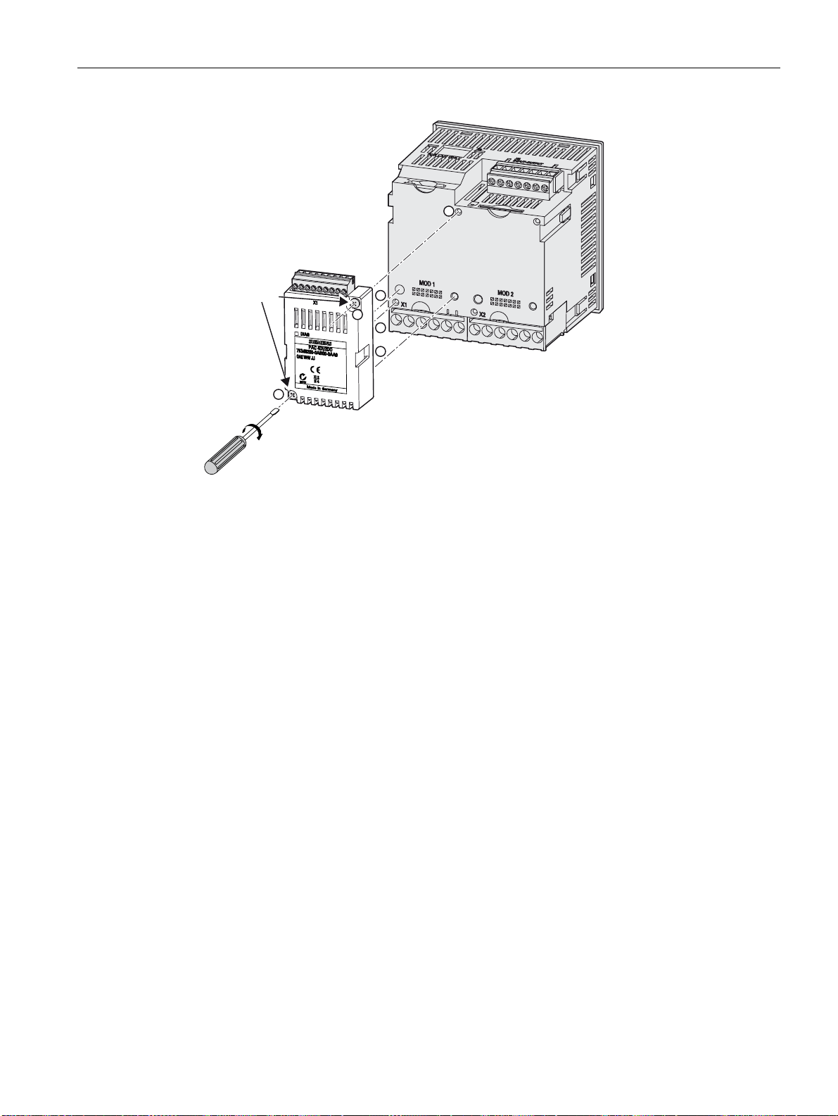
Installation
5.5 Installing the expansion modules
[
61%[
1P
See also
Figure 5-5 Schematic view of assembling the expansion module
1. Ensure safe isolation from supply.
2. Discharge yourself.
3. Mount the SENTRON PAC Power Monitoring Device.
4. Connect the current terminals and voltage terminals to the SENTRON PAC.
5. Always hold the expansion module by the plastic enclosure.
6. Connect the expansion module to the SENTRON PAC. The guide for correct position of
the guide pins will help you to plug in the expansion module correctly.
7. Tighten the SN62217-B3x22 screws connecting the expansion module to the
SENTRON PAC with a torque of 0.5 Nm.
Electrostatic sensitive devices (ESD) (Page 273)
Operation planning (Page 63)
Tools (Page 69)
Connecting the PAC RS485 expansion module (Page 96)
Mounting on the switching panel (Page 70)
SENTRON PAC4200
System Manual, 09/2009, A5E02316180B-02
75
Page 76

Installation
5.6 Deinstalling
5.6 Deinstalling
Shutting down
Make sure the device has been shut down before you begin to deinstall it.
Tools
You require the following tools to deinstall the device:
● PH2 screwdriver
● Slotted screwdriver
Deinstallation steps
1. Discharge any static from your body in accordance with the ESD guidelines.
CAUTION
Electrostatic sensitive devices
Ground your body. Discharge your body of any static electricity.
2. Start deinstallation on the inside of the switching panel.
3. Release the clamping arrangement on the switching panel. To do so, unscrew the four
screws on the two brackets. Leave the screws in the brackets.
4. Carefully lever the locking hooks open with the slotted screwdriver or another suitable
tool. The bracket releases immediately.
5. Go to the outside of the switching panel and remove the device from the cutout.
6. Pack the device into the original box together with the operating instructions and the
delivered components listed in the operating instructions.
Deinstallation is complete.
SENTRON PAC4200
76 System Manual, 09/2009, A5E02316180B-02
Page 77
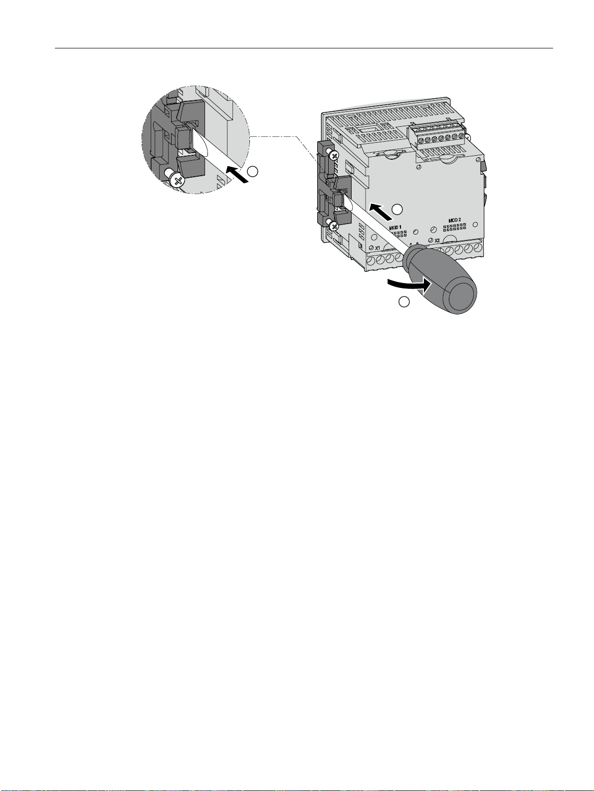
Installation
5.7 Disassembling an expansion module
Figure 5-6 Deinstallation, releasing the locking hooks
See also
ESD guidelines (Page 273)
Disassembling an expansion module (Page 77)
Electrostatic sensitive devices (ESD) (Page 273)
5.7 Disassembling an expansion module
Disassembling
1. Ensure safe isolation from supply.
2. Observe the ESD Guidelines. Discharge yourself. Always hold the expansion module by
the plastic enclosure.
3. Remove the terminal block from the expansion module, or detach the cable from the
terminal block.
4. Unscrew the expansion module from the SENTRON PAC Power Monitoring Device.
5. Remove the expansion module from the SENTRON PAC Power Monitoring Device.
6. If necessary, disassemble the SENTRON PAC Power Monitoring Device.
SENTRON PAC4200
System Manual, 09/2009, A5E02316180B-02
77
Page 78

Installation
5.7 Disassembling an expansion module
See also
Electrostatic sensitive devices (ESD) (Page 273)
Tools (Page 69)
Deinstalling (Page 76)
SENTRON PAC4200
78 System Manual, 09/2009, A5E02316180B-02
Page 79

Connecting
6.1 Safety notes
Instructions
DANGER
Hazardous Voltages
Will cause death, serious injury or property damage.
Turn off and lock out all power supplying this device before working on this device.
NOTICE
Improper power supply may damage equipment
Before connecting the device, check that the system voltage agrees with the voltage
specified on the type plate.
Note
Qualified Personnel
In the context of the safety information in the user documentation, a qualified person is a
person who is familiar with assembling, installing, commissioning, and operating the product
and who has the relevant qualifications, such as:
• Training or instruction/authorization in operating and maintaining devices and systems
according to the safety regulations for electrical circuits and devices.
• Is trained in the proper care and use of protective equipment in accordance with
established safety practices.
• First aid training.
6
See also
Applying the measuring voltage (Page 111)
Applying the measuring current (Page 111)
Applying the supply voltage (Page 101)
Safety notes (Page 17)
SENTRON PAC4200
System Manual, 09/2009, A5E02316180B-02
79
Page 80
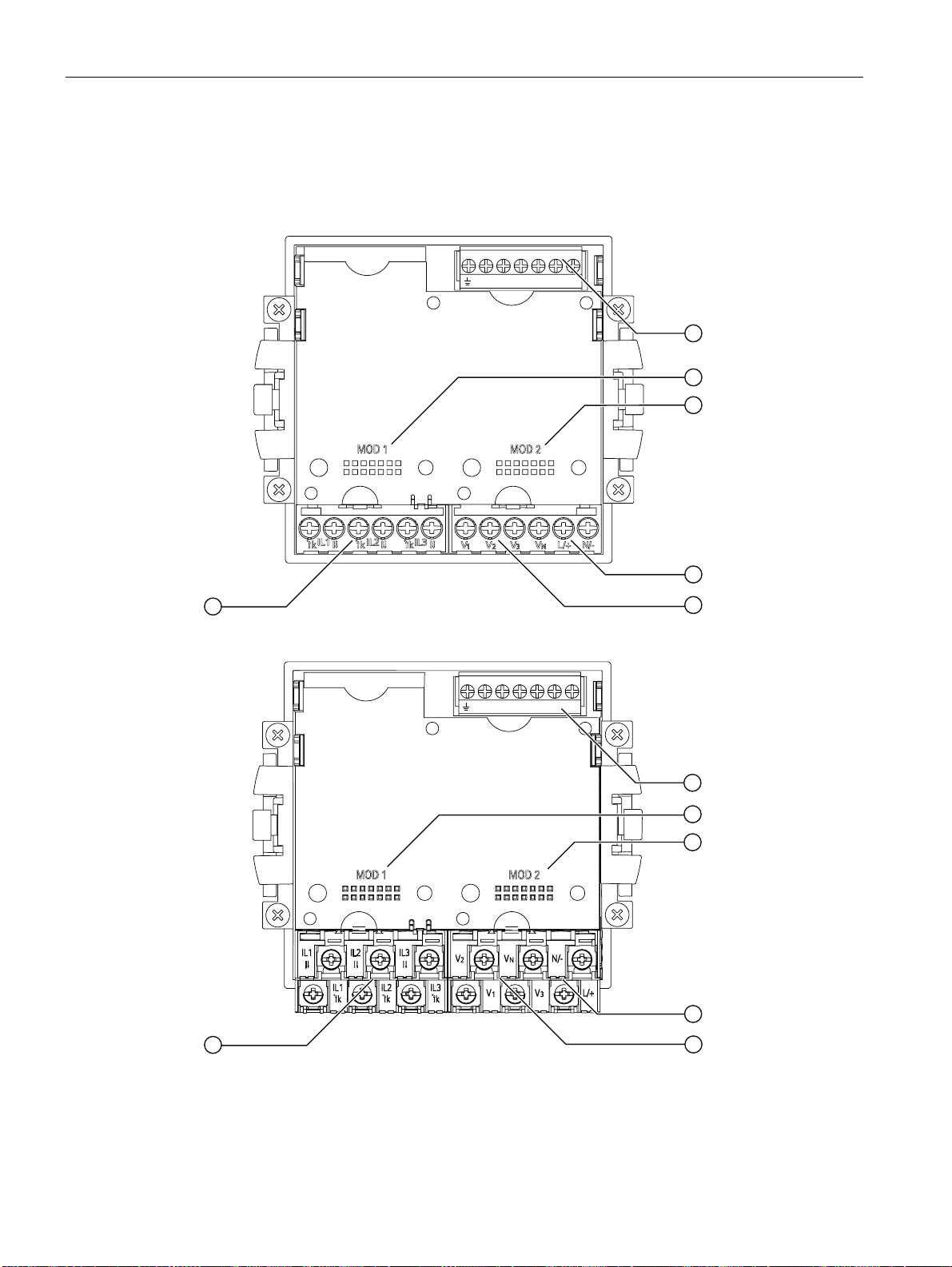
Connecting
6.2 Connections
6.2 Connections
Connection designations
DIC DI0DI1 DOC DO 0DO1
Figure 6-1 Connection designations of the device with screw terminals, rear view
DIC DI0DI1 DOC DO0DO1
Figure 6-2 Connection designations of the device with ring lug terminals, rear view
SENTRON PAC4200
80 System Manual, 09/2009, A5E02316180B-02
Page 81
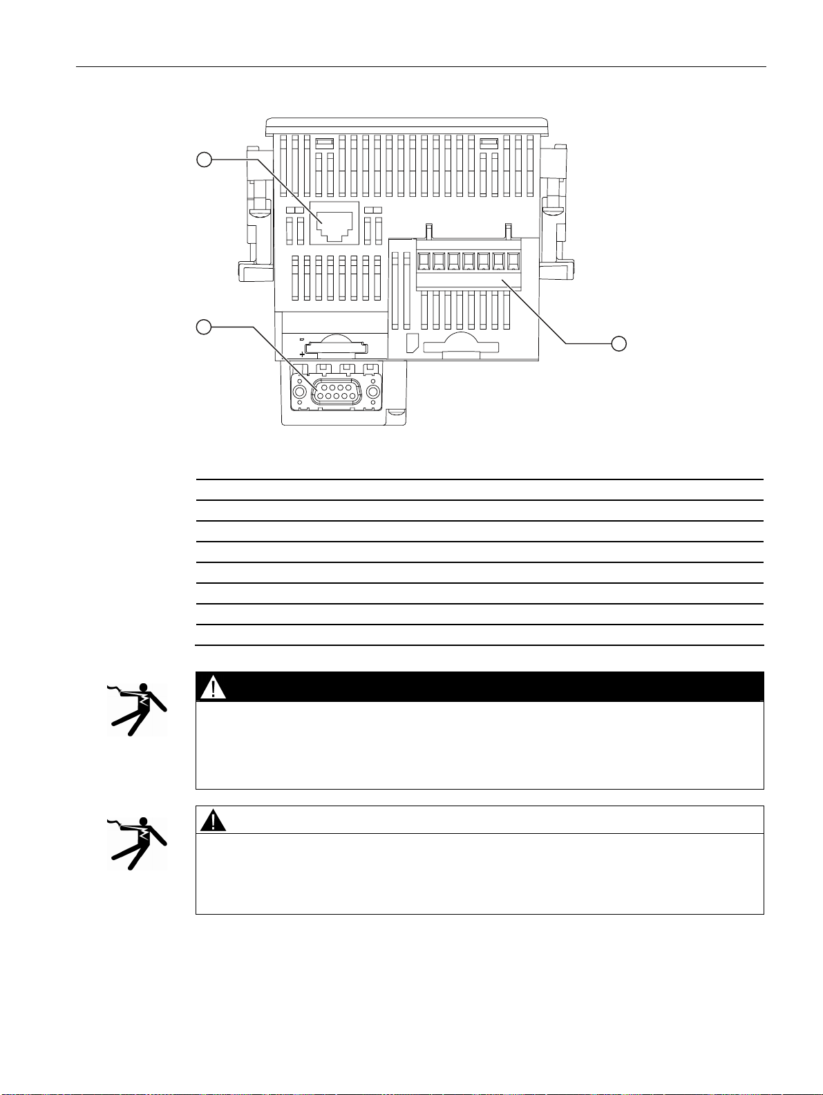
Connecting
6.2 Connections
Figure 6-3 Connection designations of the device, top view
(1) Digital inputs and outputs, reference potential
(2) 1. Slot for optional expansion module
(3) 2. Slot for optional expansion module
(4) Supply voltage L/+, N/(5) Measuring inputs voltage V1, V2, V3, VN
(6) Measuring inputs current IL1, IL2, IL3
(7) Optional expansion module, not included in scope of supply
(8) Ethernet port, RJ45
DANGER
Hazardous Voltage
Will cause death, serious injury or considerable property damage.
Observe the safety information on the device and in the operating instructions and the
manual.
CAUTION
If excessively high values are created and if the DC supply voltage is connected with the
wrong polarity, the device will be destroyed and personnel can be injured.
Ensure you do not create excessivley high values. Observe the correct polarity when
connecting DC supply voltage.
SENTRON PAC4200
System Manual, 09/2009, A5E02316180B-02
81
Page 82
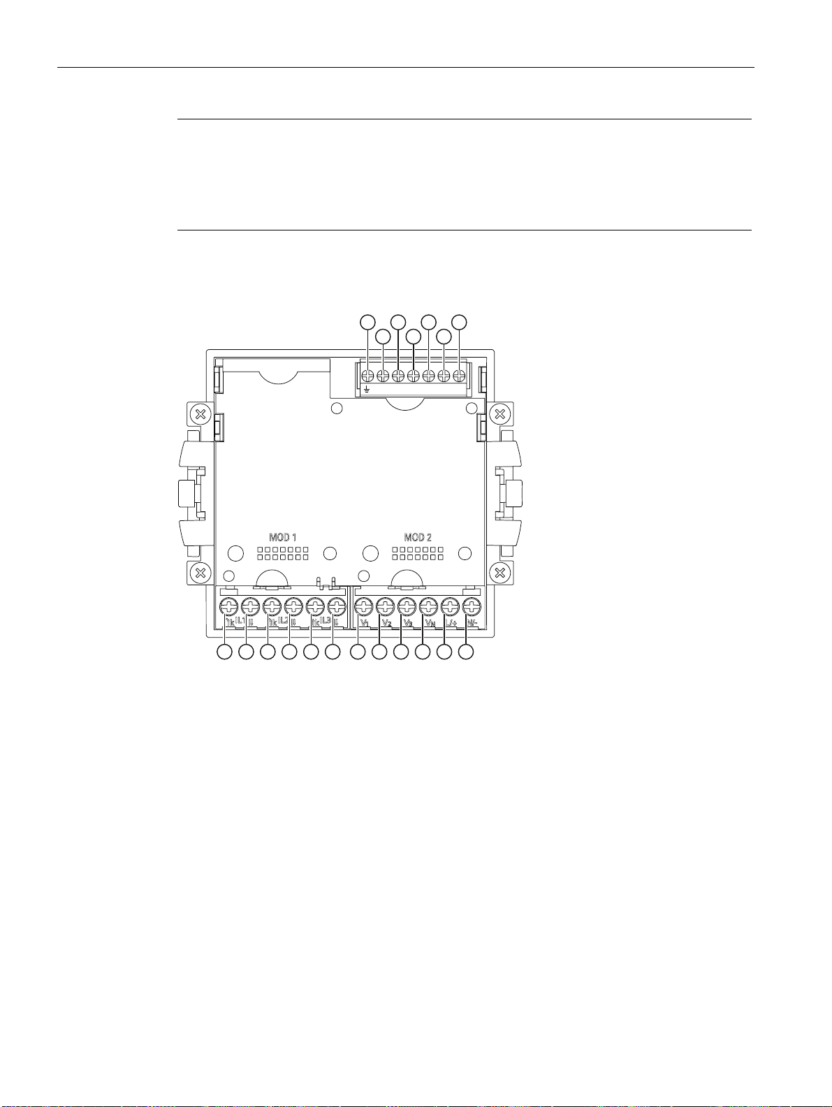
Connecting
6.2 Connections
Terminal labeling
Note
Use of devices with ring lug terminals
Designed for use in:
• NAFTA / USA
• Regions in which open terminals are permitted.
DIC DI0DI1 DOC DO0DO1
Figure 6-4 Terminal labeling, device with screw terminals
SENTRON PAC4200
82 System Manual, 09/2009, A5E02316180B-02
Page 83
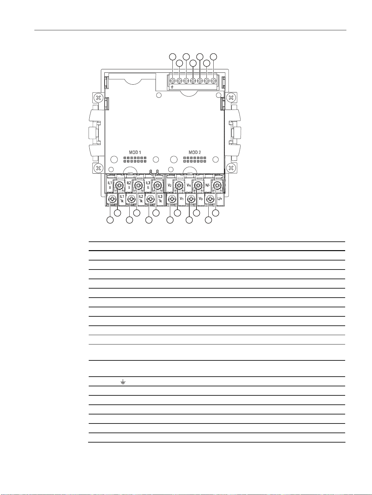
Connecting
6.2 Connections
DIC DI0DI1 DOC DO0DO1
Figure 6-5 Terminal designation, device with ring lug terminals
No. Terminal Function
(1) IL1 °↑k Current Ia, input
(2) IL1 l↓ Current Ia, output
(3) IL2 °↑k Current Ib, input
(4) IL2 l↓ Current Ib, output
(5) IL3 °↑k Current Ic, input
(6) IL3 l↓ Current Ic, output
(7) V1 Voltage V
(8) V2 Voltage V
(9) V3 Voltage V
a-n
b-n
c-n
(10) VN Neutral conductor
(11) L/+ AC: Connection: Conductor (phase-to-neutral voltage)
DC: Connection: +
(12) N/- AC: Connection: Neutral conductor
DC: Connection: -
(13)
Reference potential
(14) DIC Digital input (common)
(15) DI1 Digital input 1
(16) DI0 Digital input 0
(17) DOC Digital output (common)
(18) DO1 Digital output 1
(19) DO0 Digital output 0
SENTRON PAC4200
System Manual, 09/2009, A5E02316180B-02
83
Page 84
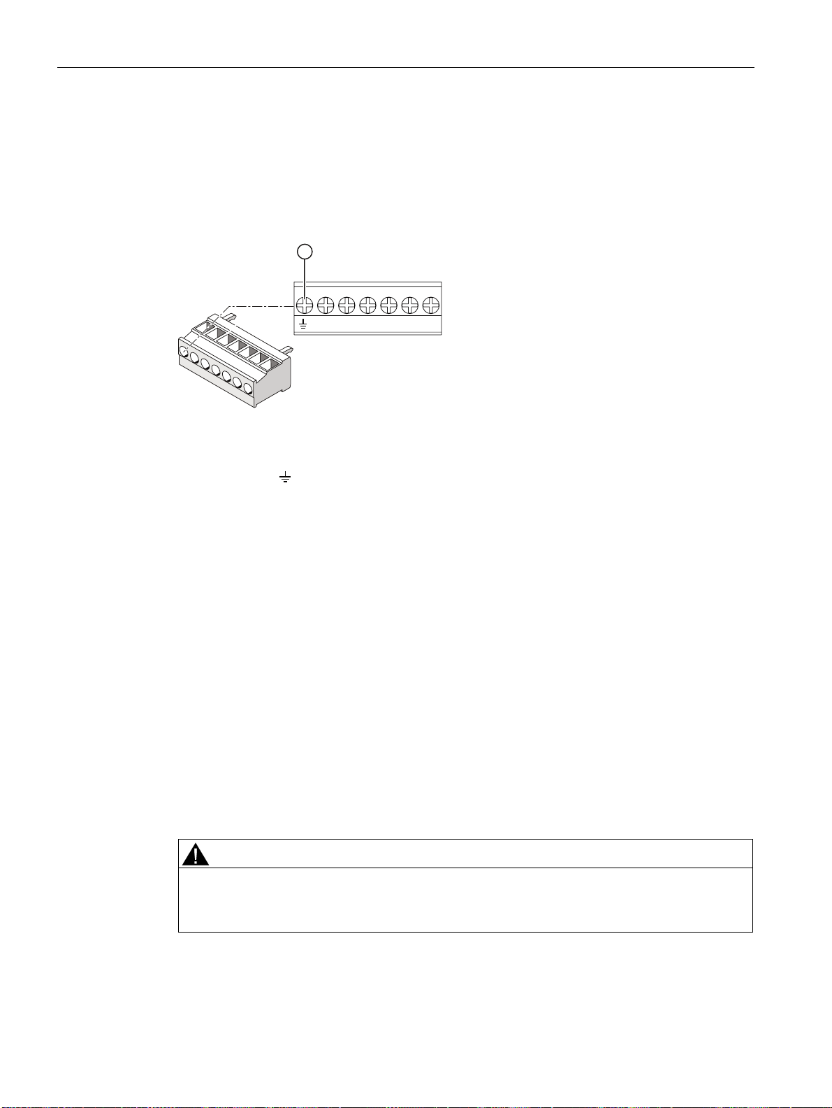
Connecting
6.2 Connections
Grounding
Conductive panels and doors on control cabinets must be grounded. The doors of the control
cabinet must be connected to the control cabinet using a grounding cable.
Reference potential
DIC DI0DI1 DOC DO0DO1
(13) Reference potential terminal
Figure 6-6 Terminal block: digital input and output, reference potential
The connection "reference potential" discharges interference affecting the digital input
and output and the RJ45 connector.
Connect the reference potential to the equipotential bonding strip in the control cabinet.
Circuit breaker
A suitable circuit breaker must be connected upstream of SENTRON PAC4200 in order to
permit disconnection of the device from the power supply.
● The circuit breaker must be mounted close to the device and be easily accessible to the
user.
● The circuit breaker must be marked as the circuit breaker for the device.
Phase-synchronous connection
The phases must be connected phase-synchronously. The specified terminal assignment
cannot be changed by changing the parameters.
Supply voltage fuse protection
CAUTION
Non-fused supply voltage may lead to device and equipment damage
Always protect the SENTRON PAC4200 with wide-range power supply with an IEC
approved or UL listed CLASS CC 0.6 A fuse.
If a fusible link is used, a suitable IEC approved or UL listed fuse holder has to be used.
SENTRON PAC4200
84 System Manual, 09/2009, A5E02316180B-02
Page 85
Connecting
6.2 Connections
Protecting the current measuring inputs
DANGER
Open transformer circuits will result in electric shock and arc flashover
Will cause death, serious injury or considerable property damage.
Only measure current with external current transformers. Do not use fuses for circuit
protection. Do not open the secondary circuit under load. Short circuit the secondary
current terminals of the current transformer before removing this device. The safety
information for the current transformers used must be followed.
Protecting the voltage measuring inputs
CAUTION
Non-fused voltage measuring points may lead to device and equipment damage.
Always protect the device with an IEC approved or UL listed 10 A fuse, circuit breaker or
supplementary protector.
Never short circuit the secondary connections of the voltage transformers.
SENTRON PAC4200
System Manual, 09/2009, A5E02316180B-02
85
Page 86
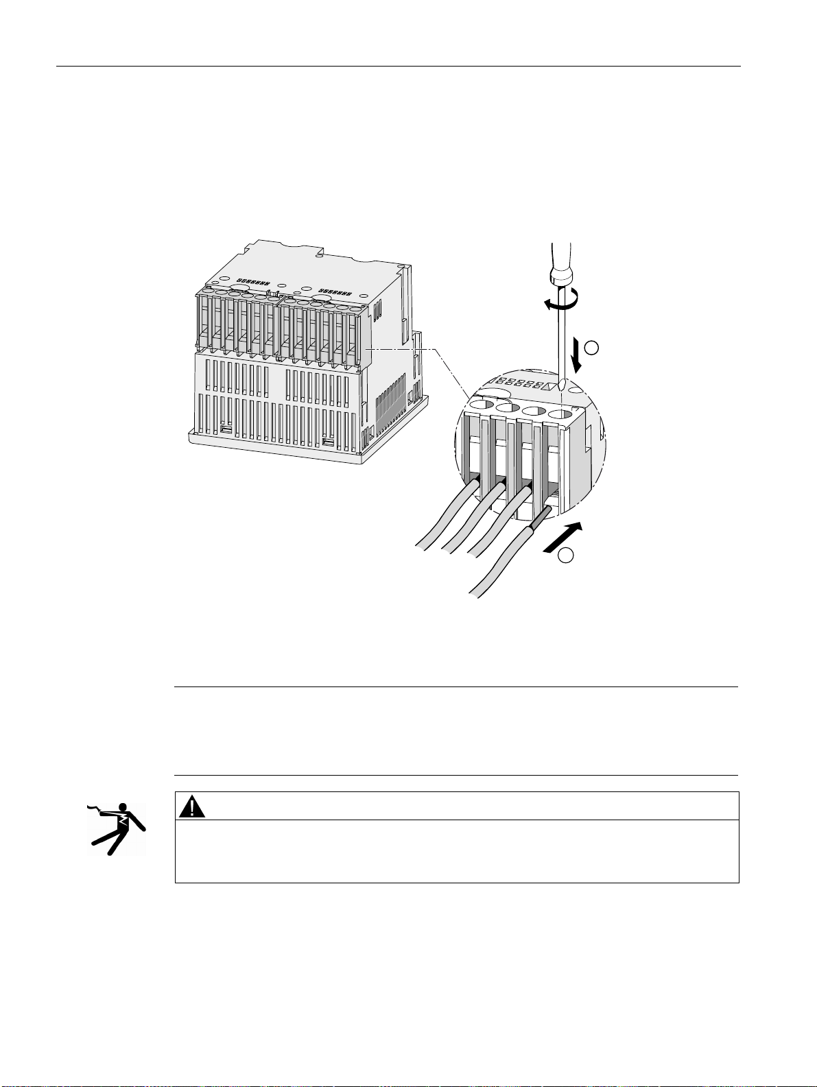
Connecting
6.3 Connecting the cables to the terminals
6.3 Connecting the cables to the terminals
Connecting cables to the screw terminal
Tool: PZ2 cal. screwdriver ISO 6789
Figure 6-7 Connecting cables to the screw terminal
Connecting the cables to the ring lug terminals:
Note
The SENTRON PAC4200 with ring lug terminal is intended for:
• use in NAFTA / USA
• Regions in which open terminals are permitted.
WARNING
Improper connection may result in death, serious injury, or property damage.
Only connect ring lugs to ring lug terminals. Ensure proper attachment of ring lugs to
cables.
Tool: PZ2 cal. screwdriver ISO 6789
SENTRON PAC4200
86 System Manual, 09/2009, A5E02316180B-02
Page 87
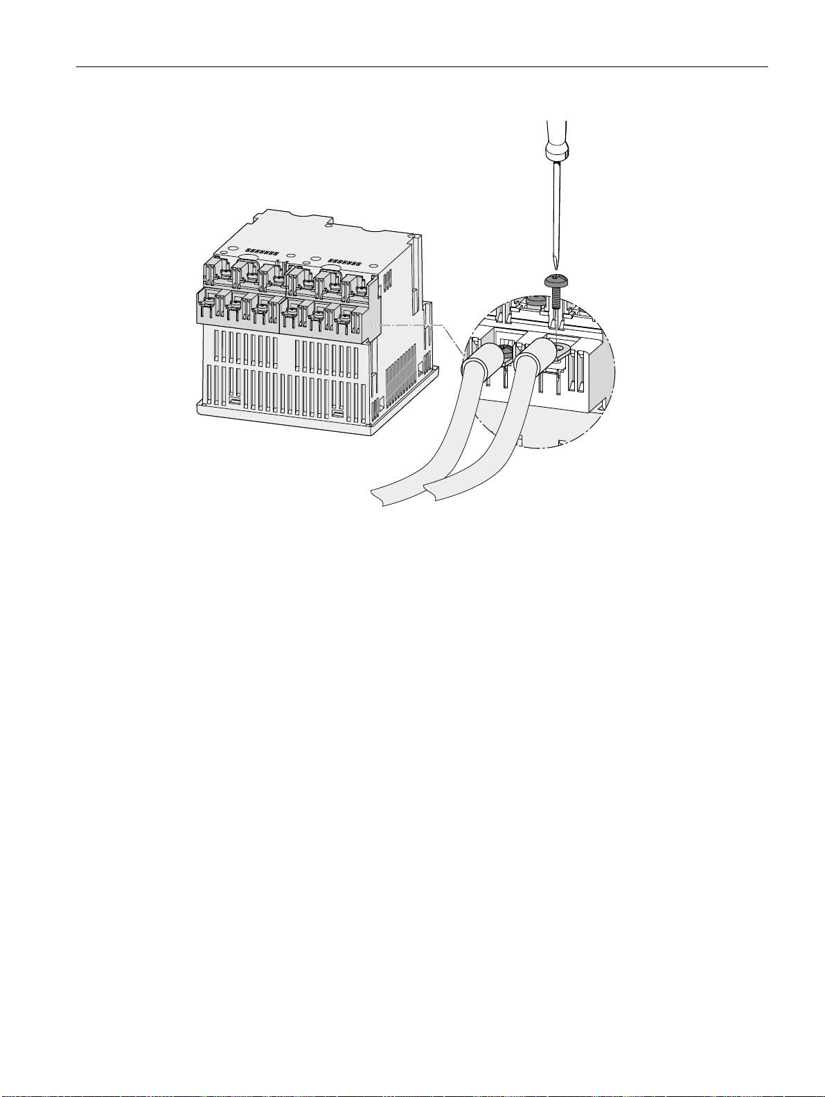
Connecting
6.4 Connection examples
Figure 6-8 Connecting the cables to the ring lug terminals:
6.4 Connection examples
Some connection examples are listed below: They show connection in:
● Two-, three- or four-wire systems
● With balanced or unbalanced load
● With/without voltage transformer
● with current transformer
The device can be operated up to the maximum permissible voltage values with or without
voltage measuring transformers.
It is only possible to measure the current with current transformers.
All input or output terminals not required for measuring remain free.
In the connection examples, the secondary side of the transformer is grounded at the "l"
terminal. It can be grounded at either the "k" or the "l" terminal. The grounding has no impact
on the measurement.
The wiring method must be made known to the device in the device settings. The connection
types given below refer to the device parameterization.
SENTRON PAC4200
System Manual, 09/2009, A5E02316180B-02
87
Page 88
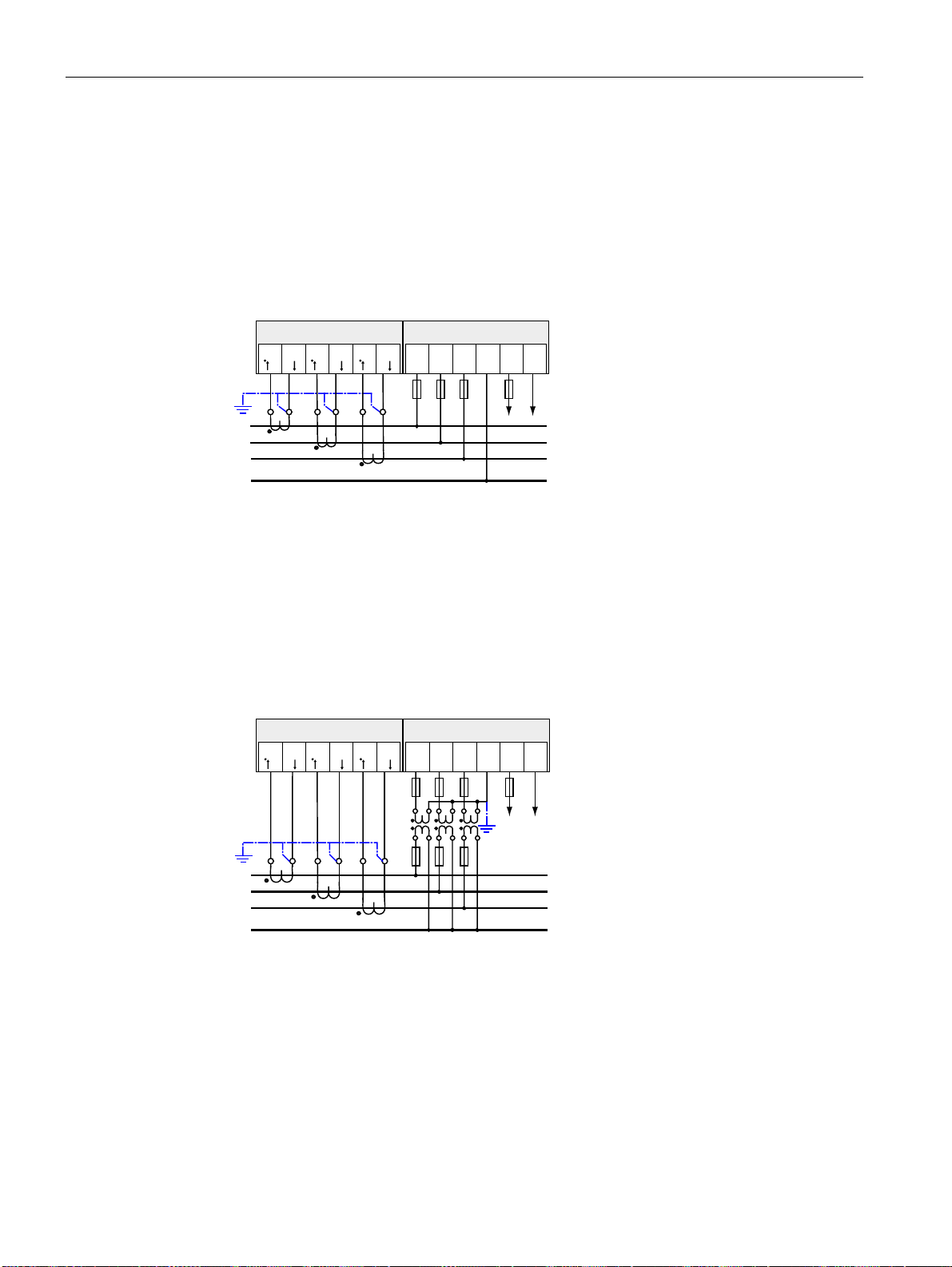
Connecting
6.4 Connection examples
Connection examples
(1) Three-phase measuring, four conductors, unbalanced load, without voltage transformers,
with three current transformers
Connection type 3P4W
; ;
,/ ,/ ,/ ,/ ,/ ,/
NO NO NO
9991
/ 19
))))
/D
/E
/F
1Q
* Fuses must be provided by the customer.
** Connection of supply voltage
Figure 6-9 Connection type 3P4W, without voltage transformer, with three current transformers
(2) Three-phase measuring, four conductors, unbalanced load, with voltage transformers,
with three current transformers
Connection type 3P4W
; ;
,/ ,/ ,/ ,/ ,/ ,/
NO NO NO
/D
/E
/F
1Q
9991
)))
)))
* Fuses must be provided by the customer.
** Supply voltage connection
Figure 6-10 Connection type 3P4W, with voltage transformer, with three current transformers
/ 19
)
SENTRON PAC4200
88 System Manual, 09/2009, A5E02316180B-02
Page 89
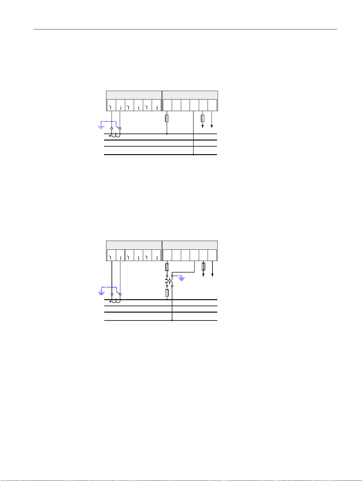
Connecting
6.4 Connection examples
(3) Three-phase measuring, four conductors, balanced load, without voltage transformers,
with one current transformer
Connection type 3P4WB
; ;
,/ ,/ ,/ ,/ ,/ ,/
NO NO NO
9991
/ 19
))
/D
/E
/F
1Q
* Fuses must be provided by the customer.
** Supply voltage connection
Figure 6-11 Connection type 3P4WB, without voltage transformer, with one current transformer
(4) Three-phase measuring, four conductors, balanced load, with voltage transformers, with
one current transformer
Connection type 3P4WB
; ;
,/ ,/ ,/ ,/ ,/ ,/
NO NO NO
/D
/E
/F
1Q
9991
)
)
* Fuses must be provided by the customer.
** Supply voltage connection
Figure 6-12 Connection type 3P4WB, with voltage transformer, with one current transformer
/ 19
)
SENTRON PAC4200
System Manual, 09/2009, A5E02316180B-02
89
Page 90
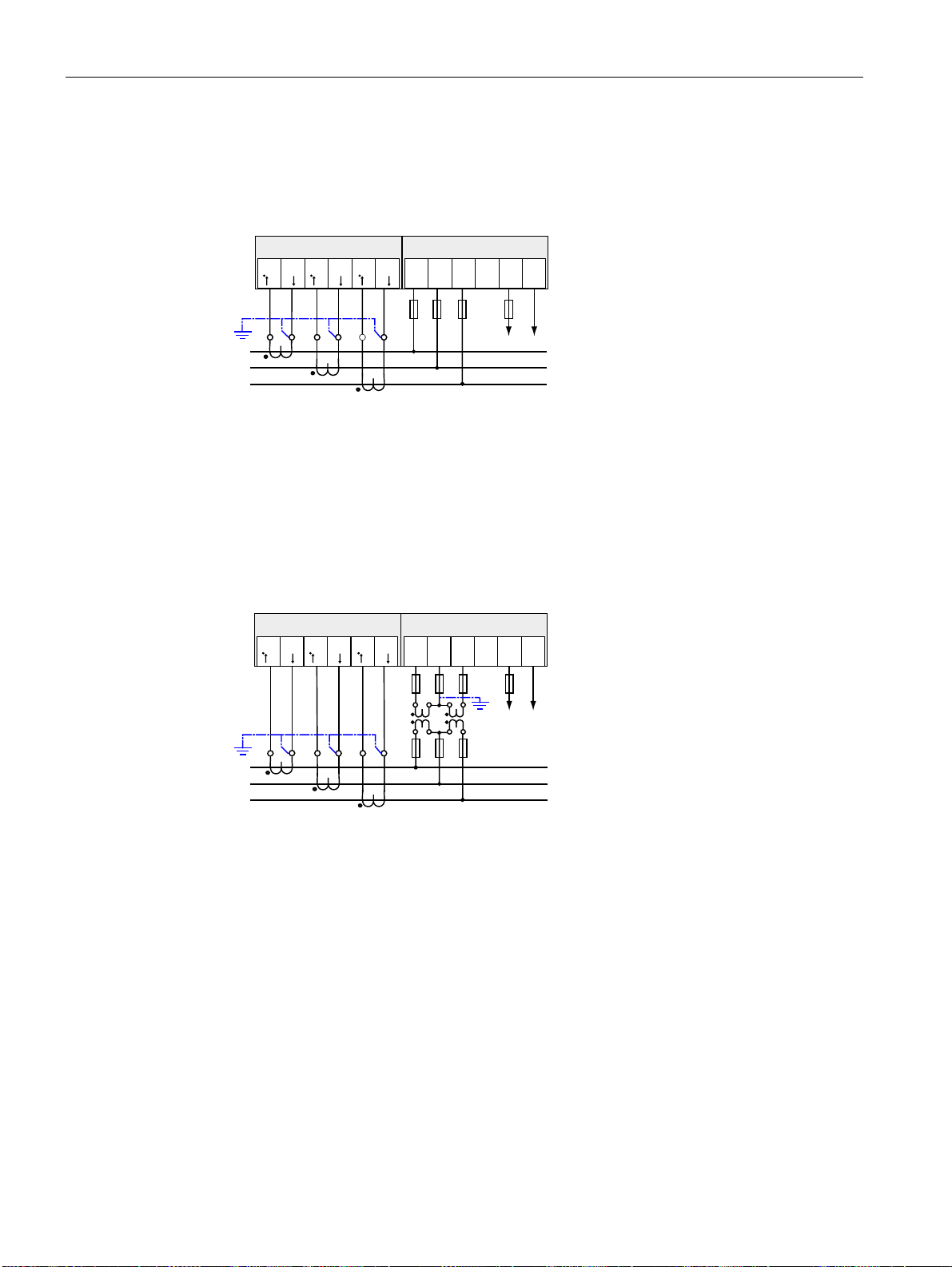
Connecting
6.4 Connection examples
(5) Three-phase measuring, three conductors, unbalanced load, without voltage
transformers, with three current transformers
Connection type 3P3W
; ;
,/ ,/ ,/ ,/ ,/ ,/
NO NO NO
9991
/ 19
))))
/D
/E
/F
* Fuses must be provided by the customer.
** Supply voltage connection
Figure 6-13 Connection type 3P3W, without voltage transformer, with three current transformers
(6) Three-phase measuring, three conductors, unbalanced load, with voltage transformers,
with three current transformers
Connection type 3P3W
; ;
,/ ,/ ,/ ,/ ,/ ,/
NO NO NO
/D
/E
/F
9991
)))
* Fuses must be provided by the customer.
** Supply voltage connection
Figure 6-14 Connection type 3P3W, with voltage transformer, with three current transformers
/ 19
))))
SENTRON PAC4200
90 System Manual, 09/2009, A5E02316180B-02
Page 91
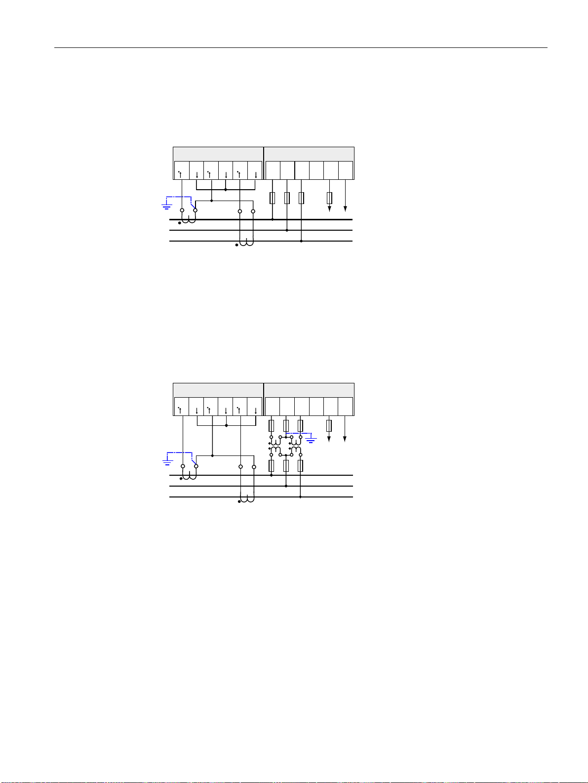
Connecting
6.4 Connection examples
(7) Three-phase measuring, three conductors, unbalanced load, without voltage
transformers, with two current transformers
Connection type 3P3W
; ;
/D
/E
/F
,/ ,/ ,/ ,/ ,/ ,/
NO NO NO
9991
) ) ))
/ 19
* Fuses must be provided by the customer.
** Supply voltage connection
Figure 6-15 Connection type 3P3W, without voltage transformer, with two current transformers
(8) Three-phase measuring, three conductors, unbalanced load, with voltage transformers,
with two current transformers
Connection type 3P3W
; ;
/D
/E
/F
,/ ,/ ,/ ,/ ,/ ,/
NO NO NO
9991
) ) )
) ) )
/ 19
)
* Fuses must be provided by the customer.
** Supply voltage connection
Figure 6-16 Connection type 3P3W, with voltage transformer, with two current transformers
SENTRON PAC4200
System Manual, 09/2009, A5E02316180B-02
91
Page 92
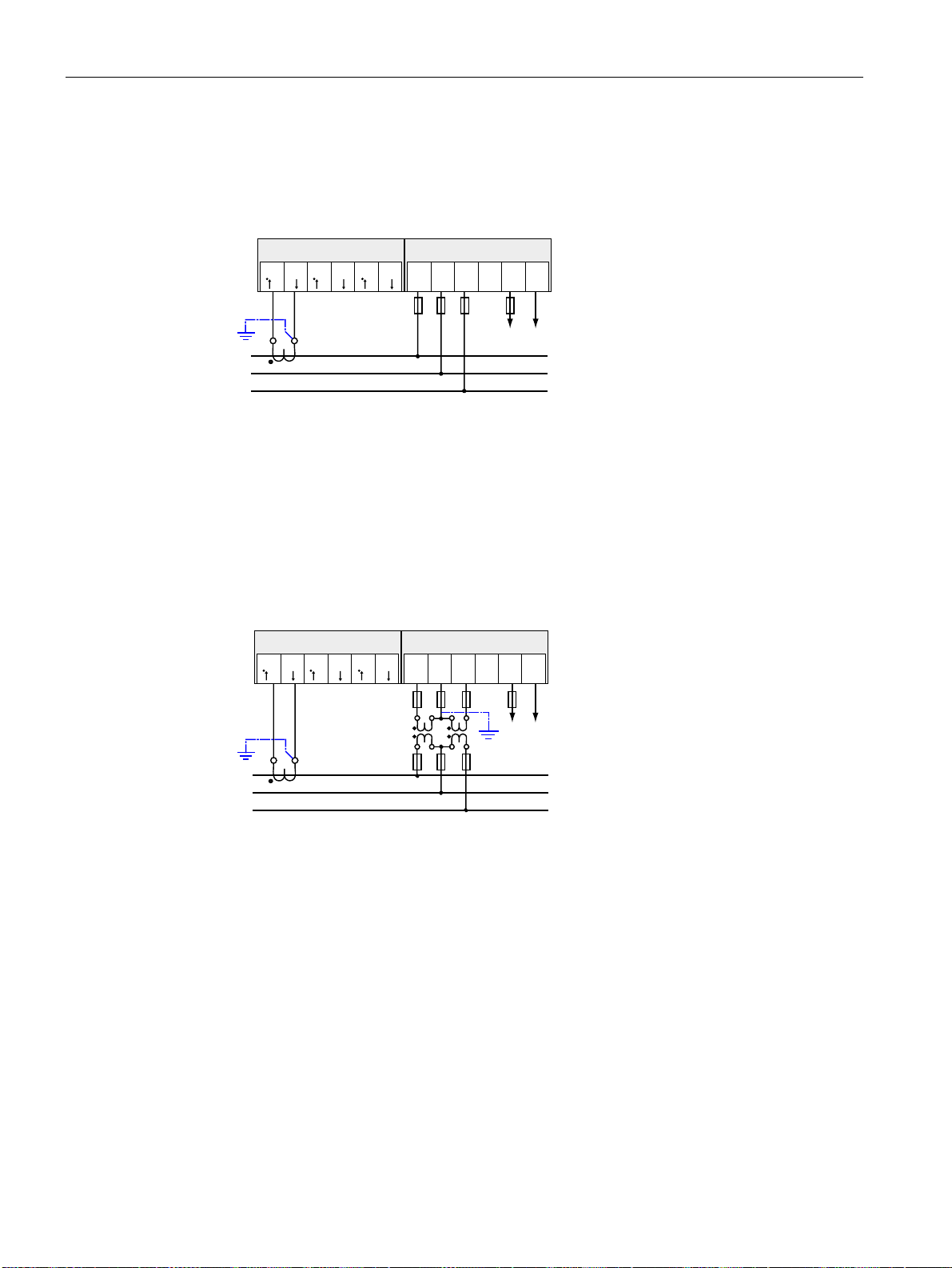
Connecting
6.4 Connection examples
(9) Three-phase measuring, three conductors, balanced load, without voltage transformers,
with one current transformer
Connection type 3P3WB
; ;
/D
/E
/F
,/ ,/ ,/ ,/ ,/ ,/
NO NO NO
9991
/ 19
))))
* Fuses must be provided by the customer.
** Supply voltage connection
Figure 6-17 Connection type 3P3WB, without voltage transformer, with one current transformer
(10) Three-phase measuring, three conductors, balanced load, with voltage transformers,
with one current transformer
Connection type 3P3WB
; ;
/D
/E
/F
,/ ,/ ,/ ,/ ,/ ,/
NO NO NO
9991
)))
/ 19
))))
* Fuses must be provided by the customer.
** Supply voltage connection
Figure 6-18 Connection type 3P3WB, with voltage transformer, with one current transformer
SENTRON PAC4200
92 System Manual, 09/2009, A5E02316180B-02
Page 93
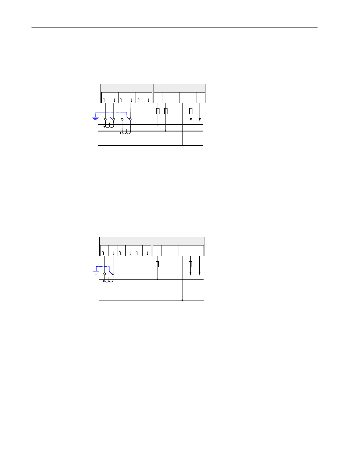
Connecting
6.4 Connection examples
(11) Two-phase measuring, three conductors, unbalanced load, without voltage
transformers, with two current transformers
Connection type 3P4W
; ;
,/ ,/ ,/ ,/ ,/ ,/
NO NO NO
9991
) ) )
/ 19
/D
/E
1Q
* Fuses must be provided by the customer.
** Supply voltage connection
Figure 6-19 Connection type 3P4W, without voltage transformer, with two current transformers
The device indicates 0 (zero) V for L3.
(12) Single-phase measuring, two conductors, without voltage transformers, with one current
transformer
Connection type 1P2W
; ;
,/ ,/ ,/ ,/ ,/ ,/
NO NO NO
/D
9991
) )
/ 19
1Q
* Fuses must be provided by the customer.
** Supply voltage connection
Figure 6-20 Connection type 1P2W, without voltage transformer, with one current transformer
SENTRON PAC4200
System Manual, 09/2009, A5E02316180B-02
93
Page 94
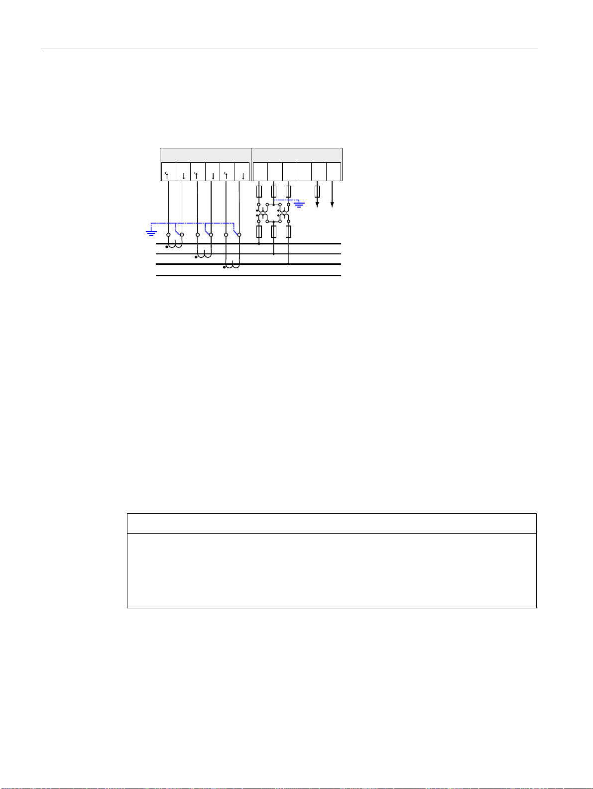
Connecting
6.5 Grounding of the Ethernet cable
(13) Three-phase measuring, four conductors, unbalanced load, with voltage transformers,
with three current transformers
Connection type 3P3W
; ;
,/ ,/ ,/ ,/ ,/ ,/
NO NO NO
/D
/E
/F
1Q
* Fuses must be provided by the customer.
** Supply voltage connection
Figure 6-21 Connection type 3P3W, with voltage transformer, with three current transformers
9991
)))
/ 19
))))
See also
Measured variables (Page 25)
Applying the supply voltage (Page 101)
6.5 Grounding of the Ethernet cable
The Ethernet cable must be grounded for data transmission according to the Fast Ethernet
standard.
NOTICE
The upper limit values will be violated if the cable is not grounded
Compliance with the technical limit values for noise radiation and noise immunity is only
guaranteed if the cable is correctly grounded. The operator of the system is responsible for
ensuring compliance with the statutory limit values (CE mark).
Make a shield connection on both sides as described here.
SENTRON PAC4200
94 System Manual, 09/2009, A5E02316180B-02
Page 95
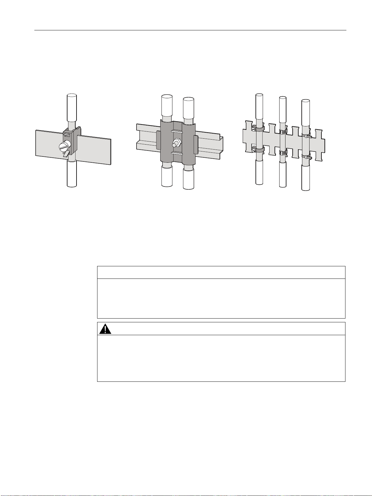
Connecting
6.5 Grounding of the Ethernet cable
Design
Ground the Ethernet cable at both ends. To do this, expose the foil shield of the Ethernet
cable. Connect the exposed shield to a suitable grounding point on the control cabinet,
preferably a shielding bus.
Figure 6-22 Grounding of the Ethernet cable
● Be careful not to damage the foil shield of the cable when removing the cable jacket.
● Fasten the exposed shield with a metal cable clamp or alternatively with a hose tie. The
clamp must clasp around a large portion of the shield and provide good contact.
● To allow good contact, a tin-plated or galvanically stabilized surface is ideal. With
galvanized surfaces, the contact should be achieved using suitable screws. A painted
surface at the contact point is not suitable.
NOTICE
Loss of contact if the shield connection is incorrectly used for strain relief
If the shield connection is used for strain relief, the grounding contact can deteriorate or
be completely lost.
Don't use the contact point on the cable shield for strain relief.
CAUTION
Damage to Ethernet Cable Shield due to Voltage Difference between Grounding Points.
If there is a voltage difference between grounding points, excessive current may flow
through the shield which is grounded at both ends.
In these cases, install an additional conductor in parallel with the Ethernet cable shield
to carry this current. Never interrupt the shield of the Ethernet cable.
SENTRON PAC4200
System Manual, 09/2009, A5E02316180B-02
95
Page 96
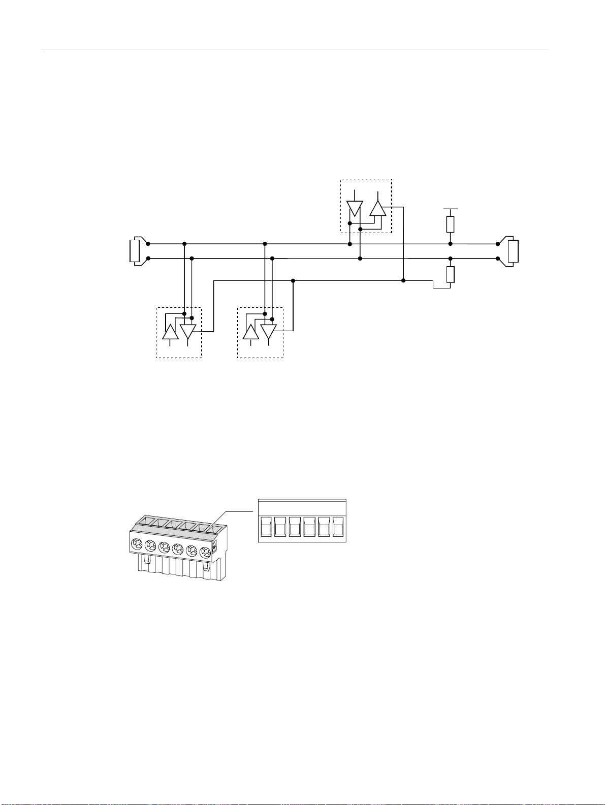
Connecting
6.6 Connecting the PAC RS485 expansion module
6.6 Connecting the PAC RS485 expansion module
Procedure
Connect the PAC RS485 expansion module to the RS 485 bus. Please pay attention to the
general topology of the twisted-pair cable.
0DVWHU
'
5
%
%DODQFHG3DLU
5
'
6ODYH 6ODYHQ
5
'
$
&RPPRQ
*URXQG
+/B B signal; D1
-/A A signal; D0
COM Common = Ground
TER (Line) Termination = bus terminating resistor
PU Pull-up resistor
PD Pull-down resistor
Figure 6-23 Block diagram: General topology of the twisted-pair cable
9
SXOOXS
38
7(57(5
SXOOGRZQ
3'
&RP % $ 7HU 38 3'
Figure 6-24 Terminal assignment
1. Connect the cables to the appropriate screw terminals on the terminal block. You can find
the assignments of the terminals in the figure "Terminal assignment".
2. Connect the cable shield at one end with protective ground PE.
3. Connect the signal Common with protective ground. This grounds the expansion module.
4. On the first and last communication nodes, switch a bus terminating resistor between the
positive signal and the negative signal. A 120-Ohm bus terminating resistor is
implemented in the PAC RS485 expansion module for this purpose. In the case of other
SENTRON PAC4200
96 System Manual, 09/2009, A5E02316180B-02
Page 97
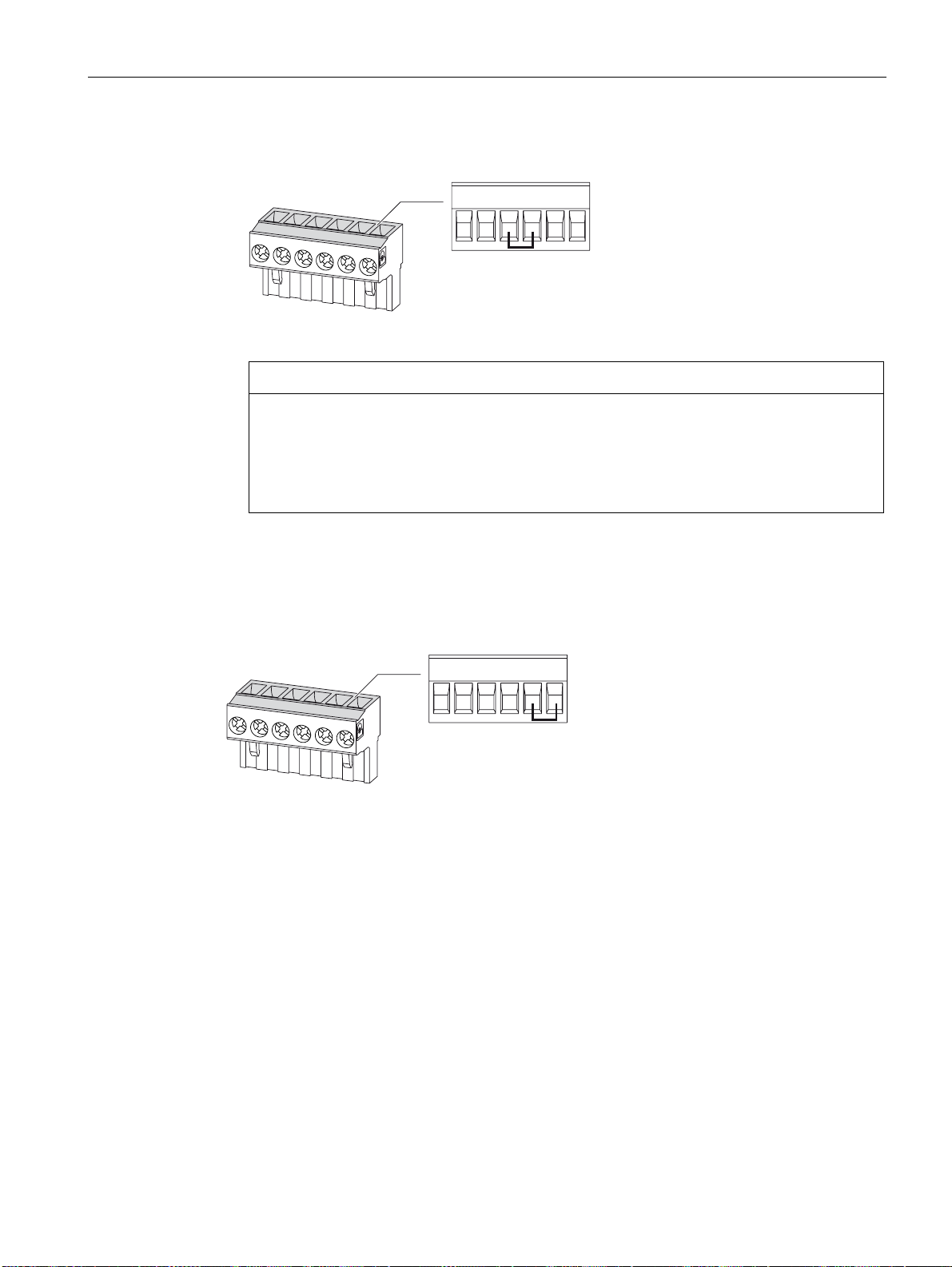
Connecting
6.6 Connecting the PAC RS485 expansion module
values, use an external bus terminating resistor. Attach this to the first and last
communication node.
&RP % $ 7HU 38 3'
Figure 6-25 Terminal assignment with terminating resistor
Line polarization
NOTICE
Incorrect bus terminator
If you switch more than two bus terminating resistors on one bus, this can result, for
example, in signal reflections that interfere with communication on the bus.
Never attach more than two bus terminators to one bus. Attach one bus terminating
resistor at the start of the bus and one terminating resistor at the end of the bus.
5. Make sure that there is sufficient strain relief for the connected cables.
A resistor for line polarization is implemented in the terminal block.
&RP % $ 7HU 38 3'
Figure 6-26 Terminal assignment with line polarization
If one or more communication nodes require line polarization, switch a resistor pair PU and
PD on the RS 485 twisted-pair cable in the case of a PAC RS485 expansion module. To do
so, switch on the resistor in the terminal block of the relevant PAC RS485 expansion module
shown in the figure "Terminal assignment with line polarization".
See also
Tools (Page 69)
Installing the expansion modules (Page 74)
Electrostatic sensitive devices (ESD) (Page 273)
SENTRON PAC4200
System Manual, 09/2009, A5E02316180B-02
97
Page 98
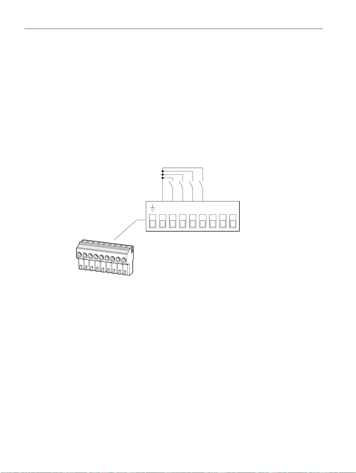
Connecting
6.7 Connecting the SENTRON PAC 4DI/2DO expansion module
6.7 Connecting the SENTRON PAC 4DI/2DO expansion module
Procedure
1. Connect the reference potential in the control cabinet to the equipotential bonding rail.
2. Connect the cables to the appropriate screw terminals on the terminal block. You can find
the assignments of the terminals in the above figures.
3. Connect the cable shield, if available, at one end with the protective conductor.
4. Connect the protective conductor PE to the "reference potential" terminal.
5. Make sure that there is sufficient strain relief for the cables.
Digital inputs
',& ', ', ', ', '2& '2 '2
DIC Digital input common
DI3 Digital input 3
DI2 Digital input 2
DI1 Digital input 1
DI0 Digital input 0
Figure 6-27 Terminal assignment with switching of the digital inputs with internal power supply
SENTRON PAC4200
98 System Manual, 09/2009, A5E02316180B-02
Page 99
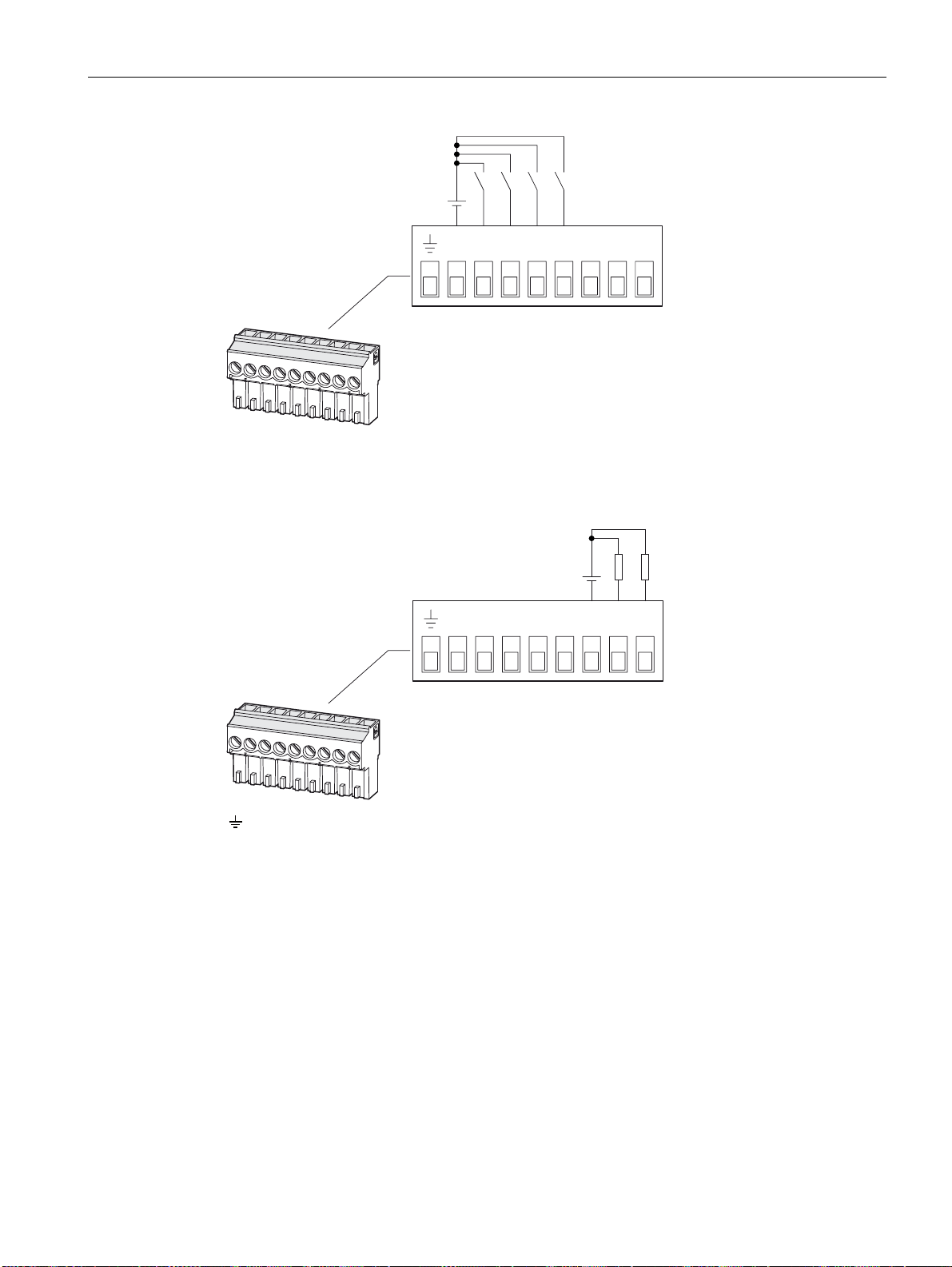
Connecting
6.7 Connecting the SENTRON PAC 4DI/2DO expansion module
',& ', ', ', ', '2& '2 '2
Figure 6-28 Terminal assignment with switching of the digital inputs with external power supply
Digital outputs
See also
',& '2', ', ', '2& '2',
Reference potential
DOC Digital output common
DO1 Digital output 1
DO0 Digital output 0
Figure 6-29 Terminal assignment with switching of the digital outputs
Technical data of the SENTRON PAC 4DI/2DO expansion module (Page 188)
Electrostatic sensitive devices (ESD) (Page 273)
Tools (Page 69)
Connecting the cables to the terminals (Page 86)
SENTRON PAC4200
System Manual, 09/2009, A5E02316180B-02
99
Page 100

Connecting
6.7 Connecting the SENTRON PAC 4DI/2DO expansion module
SENTRON PAC4200
100 System Manual, 09/2009, A5E02316180B-02
 Loading...