

Page 1

USB 3.0 Camera
STC-MBA5MUSB3
STC-MCA5MUSB3
Page 2
!
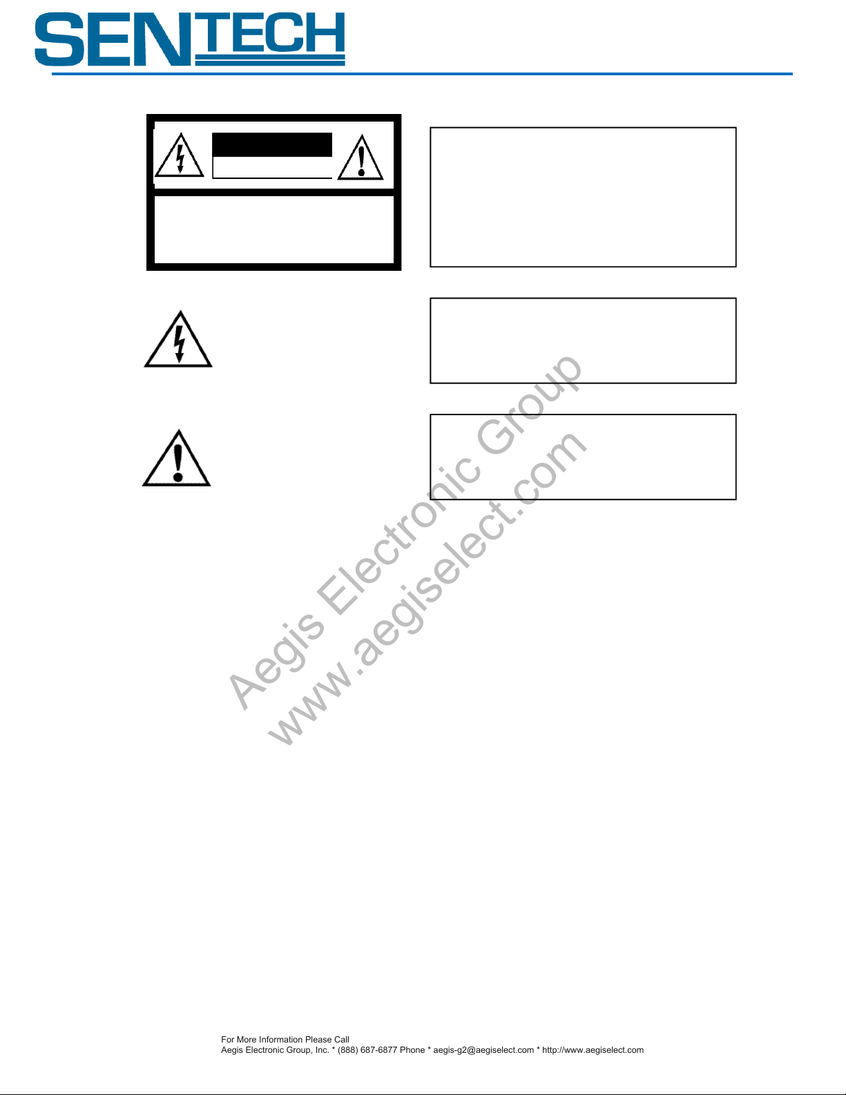
The lightning flash with arrowhead
symbol, within an equilateral triangle,
is intended to alert the user to the
presence of uninsulated “dangerous
voltage” within the product’s
enclosure that may be of sufficient
magnitude to constitute a risk of
electric shock to persons.
The exclamation point within an
equilateral triangle is intended to alert
the user to the presence of important
operating and maintenance (servicing)
instructions in the literature
accompanying the appliance.
Warning:
This equipment generates and uses radio frequency energy and if
not installed and used properly, I.e., in strict accordance with the
instruction manual, may cause harmful interference to radio
communications. It has been tested and found to comply with the
limits for a Class A computing device pursuant to Subpart J of Part
15 of FCC Rules, which are designed to provide reasonable
protection against such interference when operated in a commercial
environment.
For U.S.A.
Warning:
This digital apparatus does not exceed the Class A limits for radio
noise emissions from digital apparatus set out in the Radio
Interference Regulations of the Canadian Department of
Communications.
For Canada
WARNING:
TO PREVENT FIRE OR SHOCK HAZARD, DO NOT EXPOSE
THIS APPLIANCE TO RAIN OR MOISTURE.
Warning:
This equipment generates and uses radio frequency energy and if
not installed and used properly, I.e., in strict accordance with the
instruction manual, may cause harmful interference to radio
communications. It has been tested and found to comply with the
limits for a Class A computing device pursuant to Subpart J of Part
15 of FCC Rules, which are designed to provide reasonable
protection against such interference when operated in a commercial
environment.
For U.S.A.
Warning:
This digital apparatus does not exceed the Class A limits for radio
noise emissions from digital apparatus set out in the Radio
Interference Regulations of the Canadian Department of
Communications.
For Canada
WARNING:
TO PREVENT FIRE OR SHOCK HAZARD, DO NOT EXPOSE
THIS APPLIANCE TO RAIN OR MOISTURE.
!
CAUTION
RISK OF ELECTRIC SHOCK
DO NOT OPEN
CAUTION:
TO REDUCE THE RISK OF ELECTRIC SHOCK, DO NOT
REMOVE COVER (OR BACK). NO USER SERVICEABLE
PARTS INSIDE.
REFER SERVICING TO QUALIFIED SERVICE PERSONNEL.
Warning:
This equipment generates and uses radio frequency energy and if
not installed and used properly, I.e., in strict accordance with the
instruction manual, may cause harmful interference to radio
communications. It has been tested and found to comply with the
limits for a Class A computing device pursuant to Subpart J of Part
15 of FCC Rules, which are designed to provide reasonable
protection against such interference when operated in a commercial
environment.
For U.S.A.
Safety Precautions
For More Information Please Call
Aegis Electronic Group, Inc. * (888) 687-6877 Phone * [email protected] * http://www.aegiselect.com
Aegis Electronic Group
www.aegiselect.com
STC-MBA5MUSB3/MCA5MUSB3
Product Precautions
Handle the camera with care. Do not abuse the camera. Avoid striking or shaking it. Improper handling
or storage could damage the camera.
Do not pull or damage the camera cable.
During camera use, do not wrap he unit in any material. This will cause the internal temperature of the
unit to increase.
Do not expose the camera to moisture, or do not try to operate it in wet areas.
Do not operate the camera beyond its temperature, humidity and power source ratings.
While the camera is not being used, keep the lens or lens cap on the camera to prevent dust or
contamination from getting in the CCD or filter area and scratching or damaging this area.
Do not keep the camera under the following conditions:
In wet, moist, and high humidity areas
Under hot direct sunlight
In high temperature areas
Near an object that releases a strong magnetic or electric field
Areas with strong vibrations
Use a soft cloth to clean the camera. Use pressured air spray to clean the surface of the glass. DO not
scratch the surface of the glass.
Product Specifications 2 Ver 1.00
Page 3
STC-MBA5MUSB3/MCA5MUSB3
For More Information Please Call
Aegis Electronic Group, Inc. * (888) 687-6877 Phone * [email protected] * http://www.aegiselect.com
Aegis Electronic Group
www.aegiselect.com
Copyright & Disclaimer
Sensor Technologies America, Inc. (DBA Sentech America) believes the contents and specifications of its website, catalog,
documentation and ads are correct; however, Sentech America provides no representation or warranty regarding such information or
product(s) contained therein. It is requested that Sentech America be given appropriate acknowledgement in any subsequent use of
such work by a third party.
While every effort has been made to ensure that the details contained in Sentech America’s website and all documentation are correct
and up-to-date, Sentech America assumes no liability, legal or otherwise for any errors in listings, specifications, part numbers,
process, software or model applications. Sentech America reserves the right to change specifications, product descriptions, product
quality, pricing and application at any time without prior written or oral notice. Any party using such information assumes all risk for
any and all damaged caused to themselves, a third party and/or property by virtue of incorrect information and/or failure of these
products. By installing and/or using a Sentech America software development kit or other similar product and/or information obtained
from Sentech America’s website, catalog, documentation or ads, you hereby accept and understand these stated terms and conditions.
Product Specifications 3 Ver 1.00
Page 4
STC-MBA5MUSB3/MCA5MUSB3
For More Information Please Call
Aegis Electronic Group, Inc. * (888) 687-6877 Phone * [email protected] * http://www.aegiselect.com
Aegis Electronic Group
www.aegiselect.com
Table of Contents
I. Notes on PCs with Power Save Mode ....................................................................................................................... 5
A. Cause of the Issue ........................................................................................................................................................... 5
B. Solutions for the Issue..................................................................................................................................................... 5
II. General Specifications ......................................................................................................................................... 6-9
A. Electronic Specifications ................................................................................................................................................. 6
B. Spectral Response Characteristics ............................................................................................................................... 7-8
C. Mechanical Specifications ............................................................................................................................................... 9
D. Environmental Specifications ......................................................................................................................................... 9
III. Interface Connector Specifications ....................................................................................................................... 10
A. USB Connector .............................................................................................................................................................. 10
B. I/O Connector ............................................................................................................................................................... 10
IV. Input / Output Specifications ......................................................................................................................... 11-17
A. Input Signals ............................................................................................................................................................. 11-12
B. Output Signals .......................................................................................................................................................... 13-17
V. Dimensions .......................................................................................................................................................... 18
Product Specifications 4 Ver 1.00
Page 5

STC-MBA5MUSB3/MCA5MUSB3
For More Information Please Call
Aegis Electronic Group, Inc. * (888) 687-6877 Phone * [email protected] * http://www.aegiselect.com
Aegis Electronic Group
www.aegiselect.com
I. Notes on PCs with Power Save Mode
When the USB camera is used with a PC that has the power save mode, such as a PC with the Intel Core i3, i5, or i7
CPU, the following problem may occur.
An image cannot be obtained with the USB camera
A frame drops frequently
* The issue may occur with other USB camera manufacturers as well.
A. Cause of the Issue
The PC becomes unable to transfer the image because the CPC frequently enters the power save mode during
the image transfer.
B. Solutions for the Issue
This problem can be avoided by disabling the power save mode. However, depending on the PC, the power save
mode cannot be disabled and the desired effect may not be achieved. In addition, when the power save mode is
disabled, undesired effects such as an increase of the power consumption and the heat of the PC may occur.
1. Disable the power save mode by changing the BIOS settings.
Either set “ACPI C State” to “Disable” or decrease the “Max ACPI C State” value step by step until you see the
effect (i.e. C3->C2->C1). (The setting method and the naming may differ, and/or these settings cannot be
changed depending on the PC.)
Please contact the manufacturer of the PC about the BIOS setting.
“ACPI C State” and “Max ACPI C State” may have different names depending on the PC.
Users will be responsible for any change made to the BIOS setting.
The power consumption and the heat of the PC will increase whenever the power save mode is
disabled. Please understand and accept this before disabling the power save mode.
2. Disable the power save mode with the Sentech PC power management software (StPowerCtrl)
Please refer to the Start-Up Guide for the details.
3. Change the camera blanking period and reduce frame rate.
Product Specifications 5 Ver 1.00
Page 6
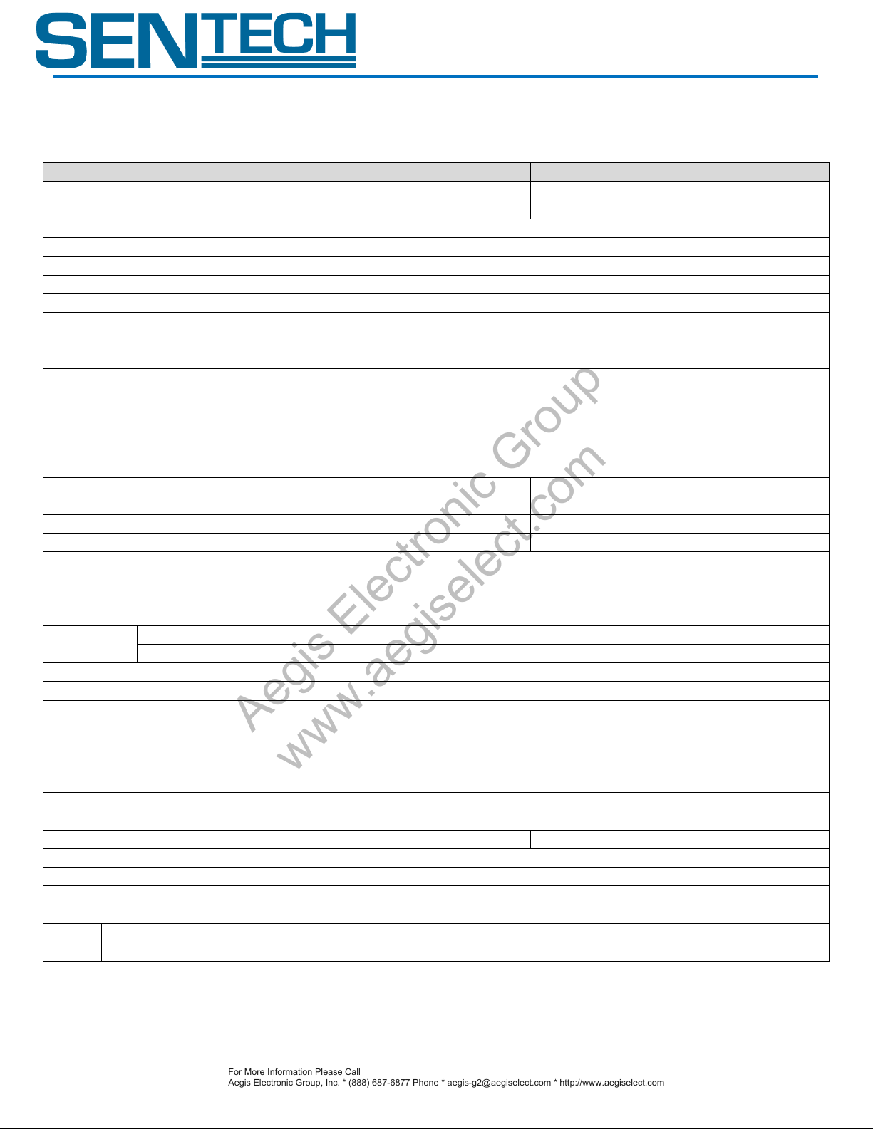
II. General Specifications
Model Number
STC-MBA5MUSB3
STC-MCA5MUSB3
Image Sensor
1/2.5″5M pixel Monochrome CMOS
(Aptina:MT9P031I12STM)
1/2.5″5M pixel Color CMOS
(Aptina:MT9P031I12STC)
Active Picture Elements
2592(H) x 1944(V)
Cell Size
2.2 (H) x 2.2 (V) µm
Scanning System
Progressive
Shutter Type
Rolling Shutter
Scanning Mode
Full Scanning, Variable AOI (Horizontal / Vertical)
Maximum Frame Rate
(in Full Scanning Mode)
QSXGA: 2592 x 1944 : 14fps (Settable from 6.88 to 14fps)
*Frame rate will drop if connected with the USB2.0 port.
(Raw 8bit output: 7fps、Raw 10/12bit output 3.5fps)
Maximum Frame Rate
(in Full Binning Scanning and AOI
Mode)
Vertical 1/2 Binning: 28fps, Vertical 1/4 Binning: 34.6fps (in full scanning mode)
QXGA (2048 x 1536) : 21fps, UXGA (1600 x 1200) : 31fps,
SXGA (1280 x 1024) : 42fps, XGA (1024 x 768) : 63fps,
SVGA (800 x 600) : 91fps, VGA (640 x 480) : 126fps,
Minimum AOI (32 x 32): 2106fps
Sync. System
Internal
Video Output Format
RAW8bit/10bit/12bit
BGR8bit,
RAW8bit/10bit/12bit, Mono8bit/10bit/12bit
S/N Ratio (8bit)
≤ 4 Digit (Gain 0 dB)
≤ 4 Digit (Gain 0 dB)
Minimum Scene Illumination
0.3 Lux at F1.2
9 Lux at F1.2
ALC
Auto Shutter / Auto Gain
Electronic Shutter
Free-run Mode: Exposure Time -- 32 µsec to 38sec (in full scanning mode)
Edge Preset Trigger Mode: Exposure Time -- 32 µsec to 38sec (in full scanning mode)
Pulse-width Trigger Mode: Exposure Time -- 32 µsec to unlimited (in full scanning mode)
Gain
Analog
0 to 26.97 dB
Digital
0 to 12.04 dB
Digital Clamp
0 to 255 (LSB of 12bit output)
Gamma
0.1 to 4.0 (settable with 0.1 step)
AOI
AOI (Horizontal: 32 to 2592 pixels / Vertical: 32 to 1944 lines)
Adjustable Steps: 4 pixels in horizontal direction and 4 lines in vertical direction
Binning Function
Horizontal 1/2, 1/4 Vertical 1/2, 1/4
*Only pixels in the horizontal direction can be added to increase the brightness.
Skipping Function
Horizontal 1/2, 1/3, 1/4, 1/5, 1/6, 1/7 Vertical 1/2, 1/3, 1/4, 1/5, 1/6, 1/7, 1/8
Mirror Image
Horizontal / Vertical / Horizontal and Vertical
Pixel Defect Correction
Up to 64 pixels (This function is turned off at shipping.)
White Balance
N/A
Auto / Manual/ One-shot
Operational Mode
Free-run / Edge-preset Trigger/ Pulse-width Trigger / Start and Stop Trigger
Frame Memory
One Frame
Interface
USB3.0 Super speed (USB3.0 Micro B)
Input/Output
Two Inputs and Two Outputs
Power
Input Voltage
+5V(typ.) (Conform to USB Standard)
Consumption
Less than 2W
For More Information Please Call
Aegis Electronic Group, Inc. * (888) 687-6877 Phone * [email protected] * http://www.aegiselect.com
Aegis Electronic Group
www.aegiselect.com
A. Electronic Specifications
STC-MBA5MUSB3/MCA5MUSB3
Product Specifications 6 Ver 1.00
Page 7
For More Information Please Call
Aegis Electronic Group, Inc. * (888) 687-6877 Phone * [email protected] * http://www.aegiselect.com
Aegis Electronic Group
www.aegiselect.com
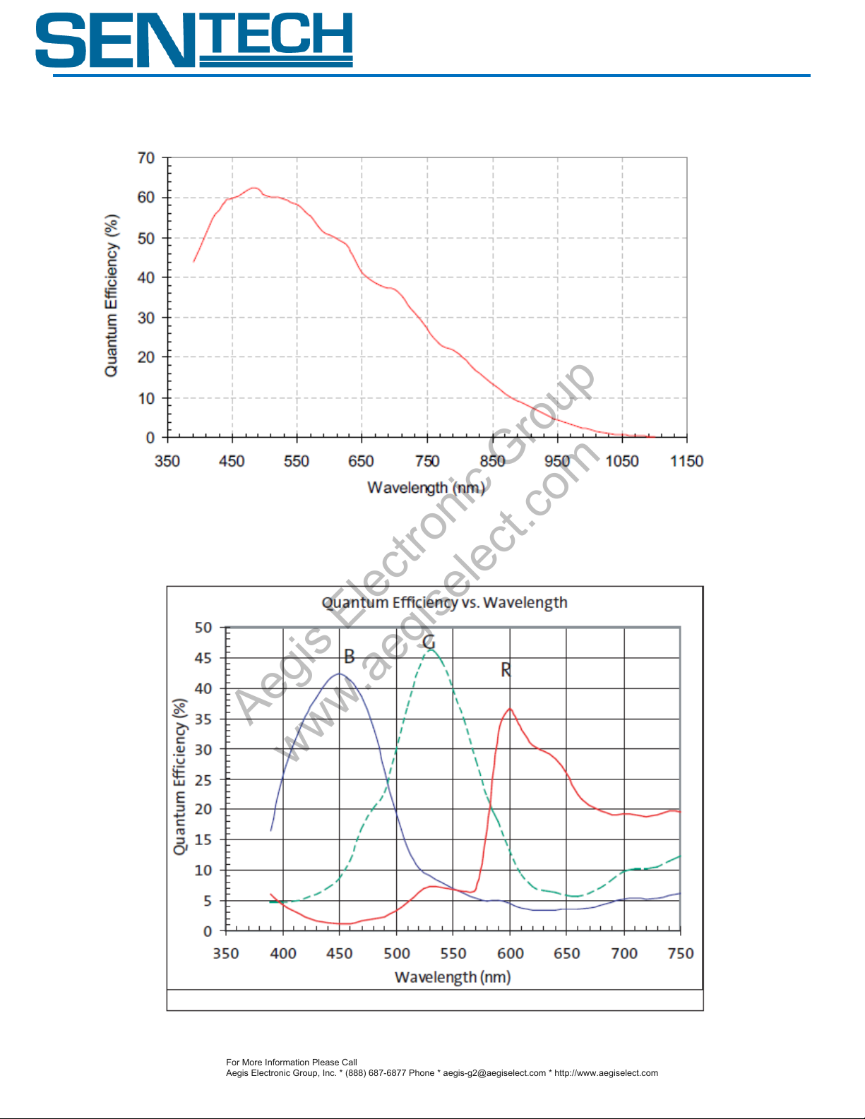
B. Spectral Sensitivity Characteristics
1. STC-MBA5MUSB3
STC-MBA5MUSB3/MCA5MUSB3
2. STC-MCA5MUSB3
Product Specifications 7 Ver 1.00
Page 8
STC-MBA5MUSB3/MCA5MUSB3
For More Information Please Call
Aegis Electronic Group, Inc. * (888) 687-6877 Phone * [email protected] * http://www.aegiselect.com
Aegis Electronic Group
www.aegiselect.com
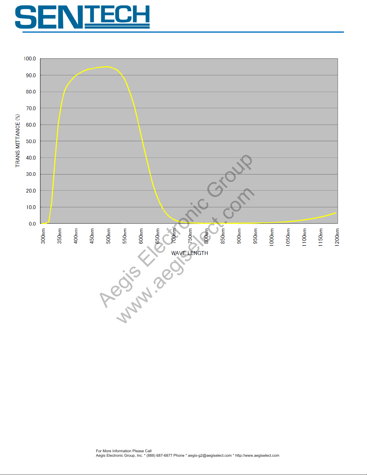
3. NF-50D (IR Cut Filter)
Product Specifications 8 Ver 1.00
Page 9

Model Number
STC-MBA5MUSB3
STC-MCA5MUSB3
Dimensions
28 (W) x 28 (H) x 33.8 (D) mm *excluding the connector
Lens Mount
CS Mount
Optical Filter
IR Cut Filter
No IR Cut Filter
Optical Center Accuracy
Positional accuracy in H and V directions: +/- 0.5 mm
Rotational accuracy of H and V: +/- 0.35 deg.
Weight
Approximately 38 g
Interface Connectors
USB Connector: USB3.0 MicroB type
I/O Connector: HR10A-7R-6PB (Hirose) or equivalent
Model Number
STC-MBA5MUSB3 / STC-MCA5MUSB3
Operational Temperature
0 ~ +40℃
Storage Temperature
-30 ~+65℃
Vibration
20Hz to 200Hz to 20Hz (5min./cycle), acceleration 10G, 3 directions 30 min. each
Shock
Acceleration 38G, half amplitude 6ms, 3 directions 3 times each
Standard Compliancy
EMS: EN61000-6-2, EMI: EN55011
RoHS
RoHS Compliant
For More Information Please Call
Aegis Electronic Group, Inc. * (888) 687-6877 Phone * [email protected] * http://www.aegiselect.com
Aegis Electronic Group
www.aegiselect.com
C. Mechanical Specifications
D. Environmental Specifications
STC-MBA5MUSB3/MCA5MUSB3
Product Specifications 9 Ver 1.00
Page 10
Pin No.
Signal Name
IN /
OUT
Voltage
Low
High
1
GND (IO_GND)
-
0V
2
Output 2 (IO3)
OUT
Smaller than
0.8 V
+3 to +26.4 V
3
Output 1 (IO2)
OUT
Smaller than
0.8 V
+3 to +26.4 V
4
Input 2 (IO1)
IN
Smaller than
0.7 V
+1.7 to +5 V
5
Input 1 (IO0)
IN
Smaller than
0.7 V
+1.7 to +5 V
6
Power Input
(IO_VCC)
-
+3 to +26.4Vdc
I/O Connector
USB Connector
[Back Side]
For More Information Please Call
Aegis Electronic Group, Inc. * (888) 687-6877 Phone * [email protected] * http://www.aegiselect.com
Aegis Electronic Group
www.aegiselect.com
III. Interface Connector Specifications
A. USB Connector USB 3.0 Micro-B Type
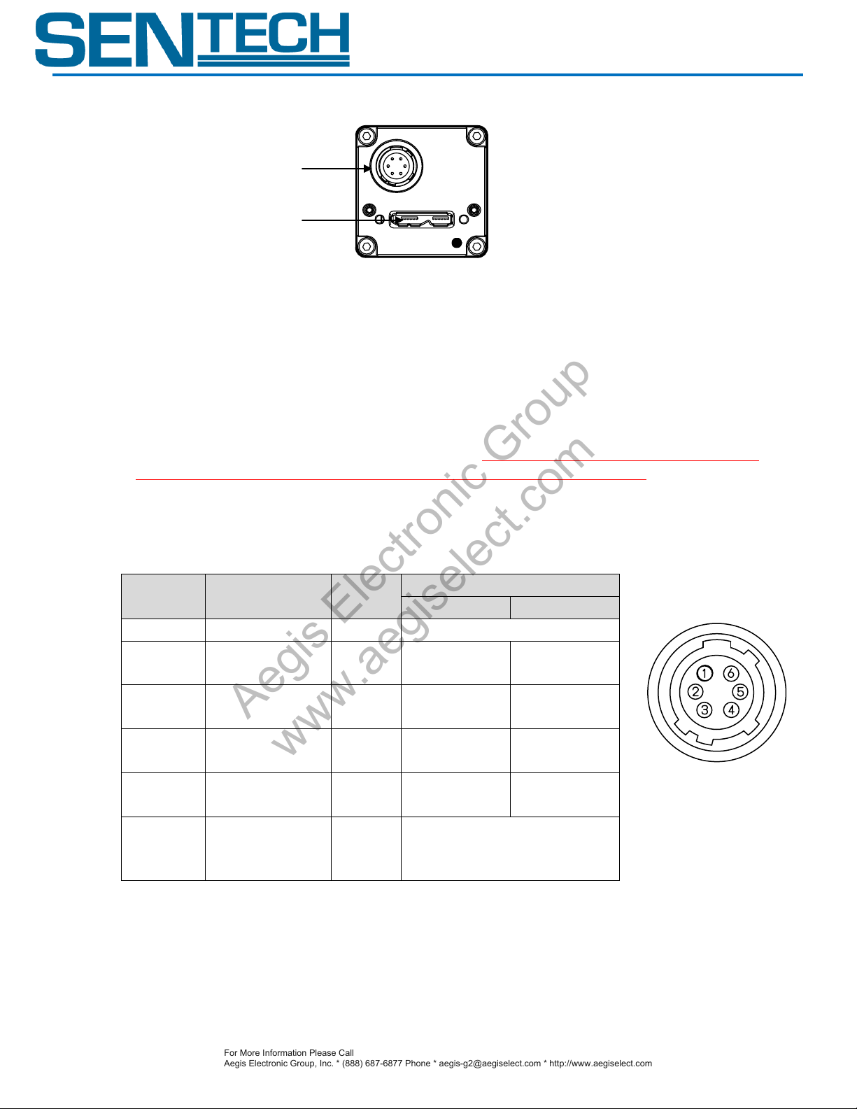
B. I/O Connector
HR10A-7R-6PB (Hirose) or equivalent
This connector is for input triggers and output signals.
Use HR10A-7P-6S (Hirose) or equivalent for the cable side.
The power input of this connector is for output signals, not for the power supply of the camera. The
camera power is provided from the USB connector via USB bus which carries +5V. This +5V does not
affect the voltage of output signals.
Pin Assignment
STC-MBA5MUSB3/MCA5MUSB3
Product Specifications 10 Ver 1.00
Page 11
STC-MBA5MUSB3/MCA5MUSB3
Function No.
Function Name
Polarity
1)
Disabled (Default)
-
2)
General Input
-
3)
Trigger Input
Positive or Negative
4)
Sub-trigger Input
Positive or Negative
For More Information Please Call
Aegis Electronic Group, Inc. * (888) 687-6877 Phone * [email protected] * http://www.aegiselect.com
Aegis Electronic Group
www.aegiselect.com
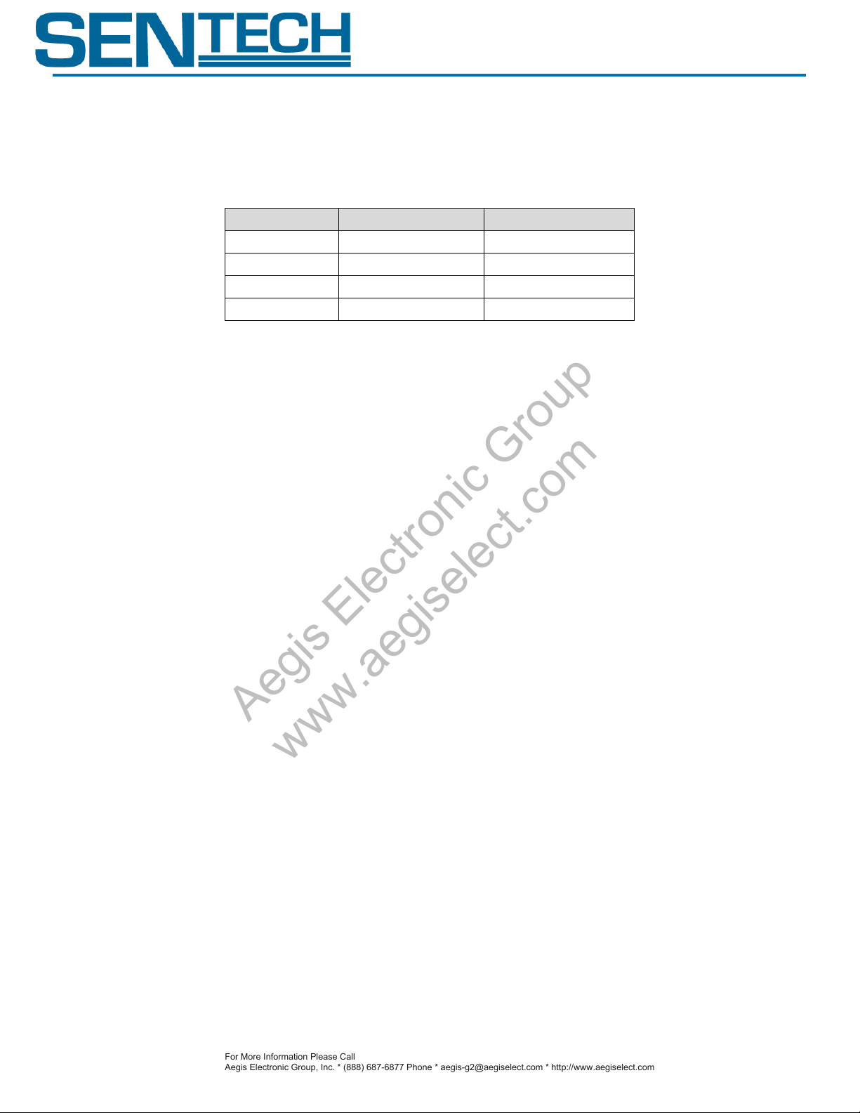
IV. Input / Output Signal Specifications A. Input Signals
1. Input Signal Functions Using the software, the following functions can be set on “Input 1” and “Input 2” of the I/O connector. The polarity of Trigger Input and Sub-Trigger Input is selectable.
1) Disabled
Set when no input signal is necessary.
2) General Input
Set high of low level and the user can check the status on the software.
3) Trigger Input
Use this function for the trigger signal in the edge preset mode and for the start trigger in the start
and stop trigger mode.
4) Sub-trigger Input
Use this function for the stop trigger in the start and stop trigger mode.
2. Input Signals Electronic Characteristics
Input Signal / Input Voltage: 0 to 5V
Input Signal / Voltage Level
High Level: 1.7V (min.)
Low Level: 0.7V (max.)
Product Specifications 11 Ver 1.00
Page 12

INPUT USER INPUT
100 ohm
10k ohm
IO_GND
internal power is applied
CUS03 (Toshiba)
1 2
IO_GND
MAX_5V
CAMERA
GND
SN74LVC2G241YZPR (TI)
INPUT
USER INPUT
100 ohm
10k ohm
IO_GND
internal power is applied
CUS03 (Tos hiba)
1 2
IO_GND
CAMERA
SN74LVC2G241YZPR (TI)
GND
Tr
MAX_5V
For More Information Please Call
Aegis Electronic Group, Inc. * (888) 687-6877 Phone * [email protected] * http://www.aegiselect.com
Aegis Electronic Group
www.aegiselect.com
3. Input Signal Circuit
4. Input Signal Circuit Examples
STC-MBA5MUSB3/MCA5MUSB3
*The voltage applied on “input 1” and “input 2” must be less than or equal to 5V, the absolute maximum input voltage.
Product Specifications 12 Ver 1.00
Page 13
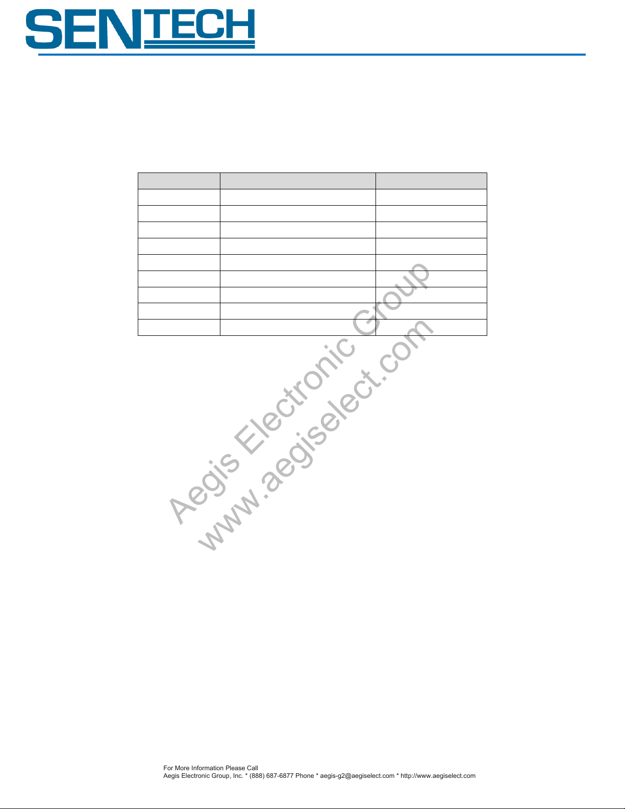
Function No.
Function Name
Polarity
1)
Disabled (Default)
-
2)
General Output
-
3)
Trigger Output Programmable
Positive or Negative
4)
Trigger Output Loop Through
Positive or Negative
5)
Exposure End
Positive or Negative
6)
Read End Output
Positive or Negative
7)
Strobe Output Programmable
Positive or Negative
8)
Strobe Output Exposure
Positive or Negative
9)
Trigger Valid Out
Positive or Negative
For More Information Please Call
Aegis Electronic Group, Inc. * (888) 687-6877 Phone * [email protected] * http://www.aegiselect.com
Aegis Electronic Group
www.aegiselect.com
B. Output Signals
1. Output Signal Functions
Using the software, the following functions can be set on “Output 1” and “Output 2” of the I/O
connector.
The polarity of Trigger Output Programmable, Trigger Output Loop Through, Exposure End, CCD Read
End Output, Strobe Output Programmable, Strobe Output Exposure and Trigger Valid Out is selectable.
Negative Polarity is recommended to use to reduce the timing delay due to open drain output.
STC-MBA5MUSB3/MCA5MUSB3
1). Disabled
Set when no output signal is necessary.
2). General Output
Outputs high or low level signal set on the software.
3). Trigger Output Programmable
Outputs the trigger input signal with delay setting applied.
4). Trigger Output Loop Through
Outputs the trigger input sign (with a slight internal delay).
5). Exposure End
Output a signal upon the completion of the first line exposure.
(“Trigger Out Delay” and “Trigger Pulse Width” settings are applied.)
6). Read End Output
Output a signal upon the completion of the transfer of a full frame.
(“Trigger Out Delay” and “Trigger Pulse Width” settings are applied.)
7). Strobe Output Programmable
Output a signal for the period set with “strobe end delay”, starting at the trigger input signal with the
addition of “strobe start delay”
8). Strobe Output
Output a signal during the first lien of exposure*.
Product Specifications 13 Ver 1.00
Page 14

STC-MBA5MUSB3/MCA5MUSB3
For More Information Please Call
Aegis Electronic Group, Inc. * (888) 687-6877 Phone * [email protected] * http://www.aegiselect.com
Aegis Electronic Group
www.aegiselect.com
9). Trigger Valid Out
With the positive polarity setting, high status indicates that the input trigger signal is acceptable. This
signal becomes low from the exposure start to the end of image output.
With the negative polarity setting, low status indicates that the input trigger signal is acceptable. This
signal becomes high from the exposure start to the end of image output.
* Because this camera is a rolling shutter type, the exposure start timing of each line is not simultaneous.
Product Specifications 14 Ver 1.00
Page 15
STC-MBA5MUSB3/MCA5MUSB3
2.04 [us]
1.16 [us]
0.66 [us]
0.56 [us]
Tf
0.70 [us]
0.56 [us]
0.56 [us]
0.50 [us]
Ts
1.44 [us]
1.16 [us]
0.84 [us]
0.82 [us]
Tr
1.60 [us]
1.66 [us]
1.82 [us]
2.00 [us]
Td
24[V]
12[V]
5.0[V]
3.3[V]
IO_VCC
10%
90%
Td
Ts
Tr
Tf
INTERNAL SIGNAL
USER OUTPUT
3.3V
0V
IO_VCC
IO_GND
For More Information Please Call
Aegis Electronic Group, Inc. * (888) 687-6877 Phone * [email protected] * http://www.aegiselect.com
Aegis Electronic Group
www.aegiselect.com
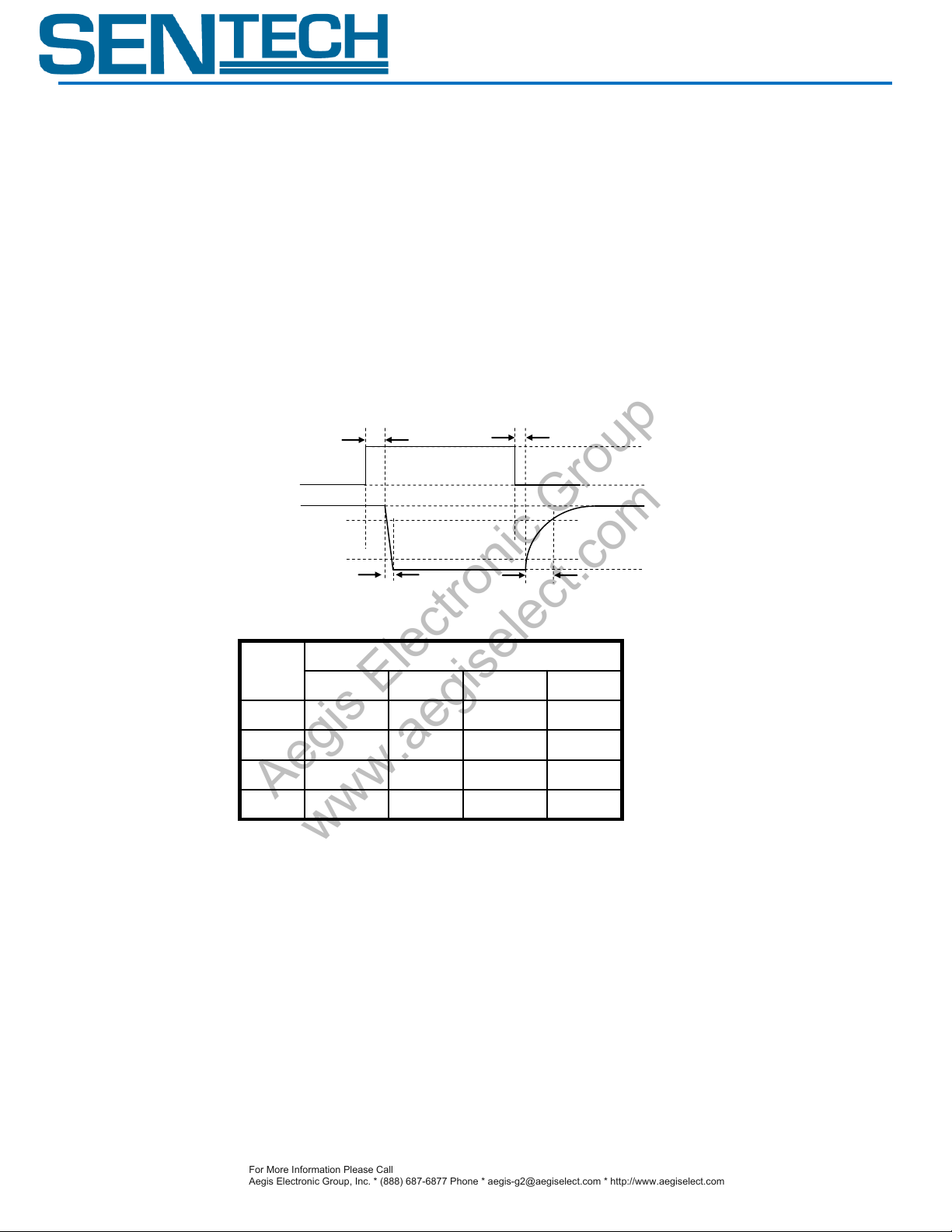
2. Output Signal Electronic Characteristics
Output Signal / Voltage Level
High Level: Power Input of the I/O Connector (+3 ~ + 26.4 V)
Low Level: Smaller than 0.8 V
Output Signal / Pulse Width
Pulse width is settable using the software.
Please refer to the response timing chart below and set with a sufficient margin.
Output Signal / Response Timing
The response timing shown below is a reference value measured without an eternal resistance.
Product Specifications 15 Ver 1.00
Page 16
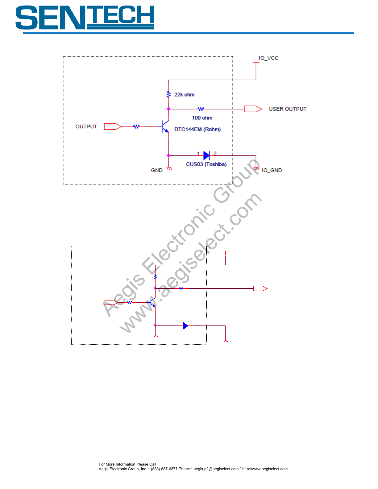
3. Output Signal Circuit
USER OUTPUT
DTC144EM (Rohm)
22k ohm
IO_VCC
CUS03 (Tos hiba)
1 2
IO_GND
OUTPUT
CAMERA
100 ohm
GND
For More Information Please Call
Aegis Electronic Group, Inc. * (888) 687-6877 Phone * [email protected] * http://www.aegiselect.com
Aegis Electronic Group
www.aegiselect.com
STC-MBA5MUSB3/MCA5MUSB3
4. Output Signal Circuit Examples
*The voltage applied on the “IO_VCC” must be within the range of +3V to 26.4V.
Product Specifications 16 Ver 1.00
Page 17
STC-MBA5MUSB3/MCA5MUSB3
IO_VCC
USER_GND
USER OUTPUT
DTC144EM (Rohm)
22k ohm
IO_GND
CUS03 (Toshiba)
1 2
CAMERA
OUTPUT
100 ohm
GND
USER_VCC
N.C
USER_Ic
For More Information Please Call
Aegis Electronic Group, Inc. * (888) 687-6877 Phone * [email protected] * http://www.aegiselect.com
Aegis Electronic Group
www.aegiselect.com
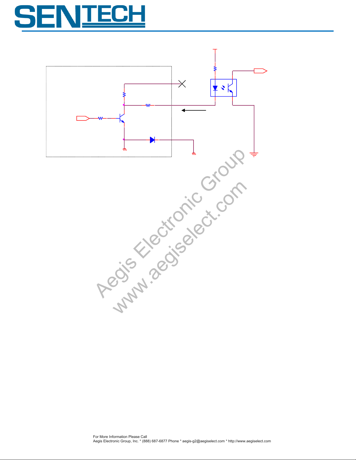
* When no voltage is applied on “IO_VCC”, it can be used as an open collector output.
* The voltage applied on “IO2” and “IO3” (USER_VCC) must be less than or equal to 26.4V.
* The incoming current to “IO2” and “IO3” (USER_lc) must be less than or equal to 15mA.
Product Specifications 17 Ver 1.00
Page 18

V. Dimensions
Unit: mm
STC-MBA5MUSB3
STC-MCA5MUSB3
For More Information Please Call
Aegis Electronic Group, Inc. * (888) 687-6877 Phone * [email protected] * http://www.aegiselect.com
Aegis Electronic Group
www.aegiselect.com
STC-MBA5MUSB3/MCA5MUSB3
*How to Identify Monochrome and Color Camera.
Product Specifications 18 Ver 1.00
Page 19
Revisions
Rev
Date
Changes
Note
.01
April, 5 2012
New document
.02
April 12, 2012
Corrected Maximum Frame Rate for VGA
.03
April 20, 2012
Added Interface Connector Specifications
1.00
October 25, 2012
Full Release Document
STC-MBA5MUSB3/MCA5MUSB3
Product Specifications 19 Ver 1.00
 Loading...