

Page 1
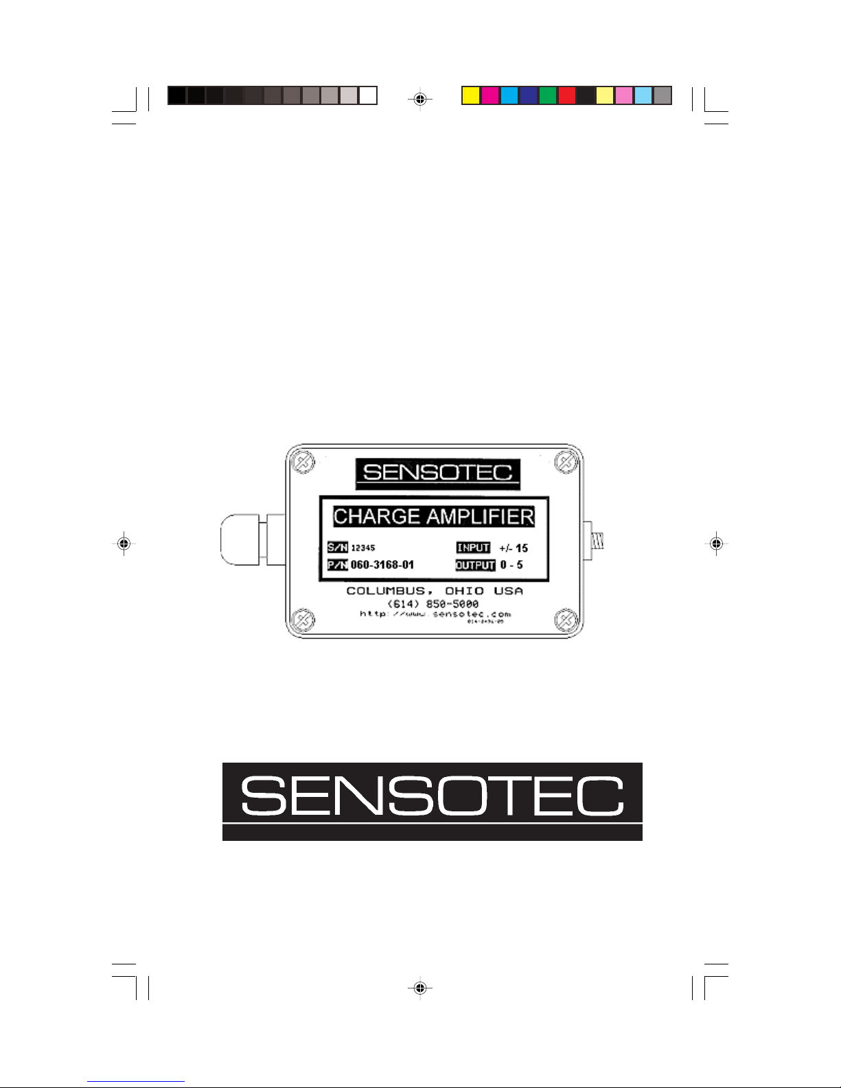
INLINE CHARGE
AMPLIFIER
MODEL CA2
2080 ARLINGATE LANE, COLUMBUS OHIO 43228 (614) 850-5000
008-0508-00
Page 2

Inline Charge Amplifier
Model CA2 User's Guide
Sensotec Part Number: 008-0508-00
Rev. 0: August, 1997
Copyright Notice:
Copyright @ 1993 by SENSOTEC, INC.
2080 Arlingate Lane
Columbus, Ohio 43228
U.S.A.
All rights Reserved.
Printed in U.S.A.
TEL (614) 850-5000
FAX (614) 850-1111
1-800-848-6564
008-0508-00
Page 3

TABLE OF CONTENTS
CHAPTER 1: INTRODUCTION
Page Number
1.1 Overview..........................................
1.2 Specifications...................................
1.3 Layout..............................................
CHAPTER 2: INSTALLATION / SET UP
2.1 Wiring................................................
2.2 Sensitivity Switch Setup....................
2.3 Panel Mounting Information...............
CHAPTER 3: CALIBRATION
3.1 Calibration.........................................
3.2 Long Time Constant Option..............
CHAPTER 4: WARRANTY / REPAIR POLICY
4.1 Limited Warranty on Products............
4.2 Obtaining Service Under Warranty....
4.3 Obtaining Non-Warranty Service.......
4.4 Repair Warranty................................
APPENDIX A......................................................
1-1
1-1
1-2
2-1
2-2
2-3
3-1
3-3
4-1
4-1
4-2
4-2
A-1
008-0508-00
Page 4

008-0508-00
Page 5

Chapter 1
INTRODUCTION
1.1 OVERVIEW
Charge mode piezoelectric transducers require charge amplifiers to
convert their output to useful voltage levels. The Sensotec model 3168
Inline Charge Amplifier is a versatile convenient solution to the use of
charge mode piezoelectric transducers. The inline is housed in a small
metal package which is connected between the transducers and the
instrumentation. The amplifier features multiple sensitivity settings
creating a flexible measuring system.
1.2 SPECIFICATION
Power Requirements + / - 15 volts DC, or 24 - 32
volts DC (with -Output
voltage = 1/2 of supply)
Amplifier Characteristics
Sensitivity Programmable (.05 mV/pC to
6.4 mV/pC)
Input Range 780pC to 100,000pC
Output + / - 5V RMS max
Frequency Response Standard- 3HZ to 30kHz
Long TC-~DC to 30kHz
Time Constant Standard- 50 milliseconds
Long TC- 2,000 seconds
Short Circuit Protected + Output to - Output
008-0508-001-1
Page 6
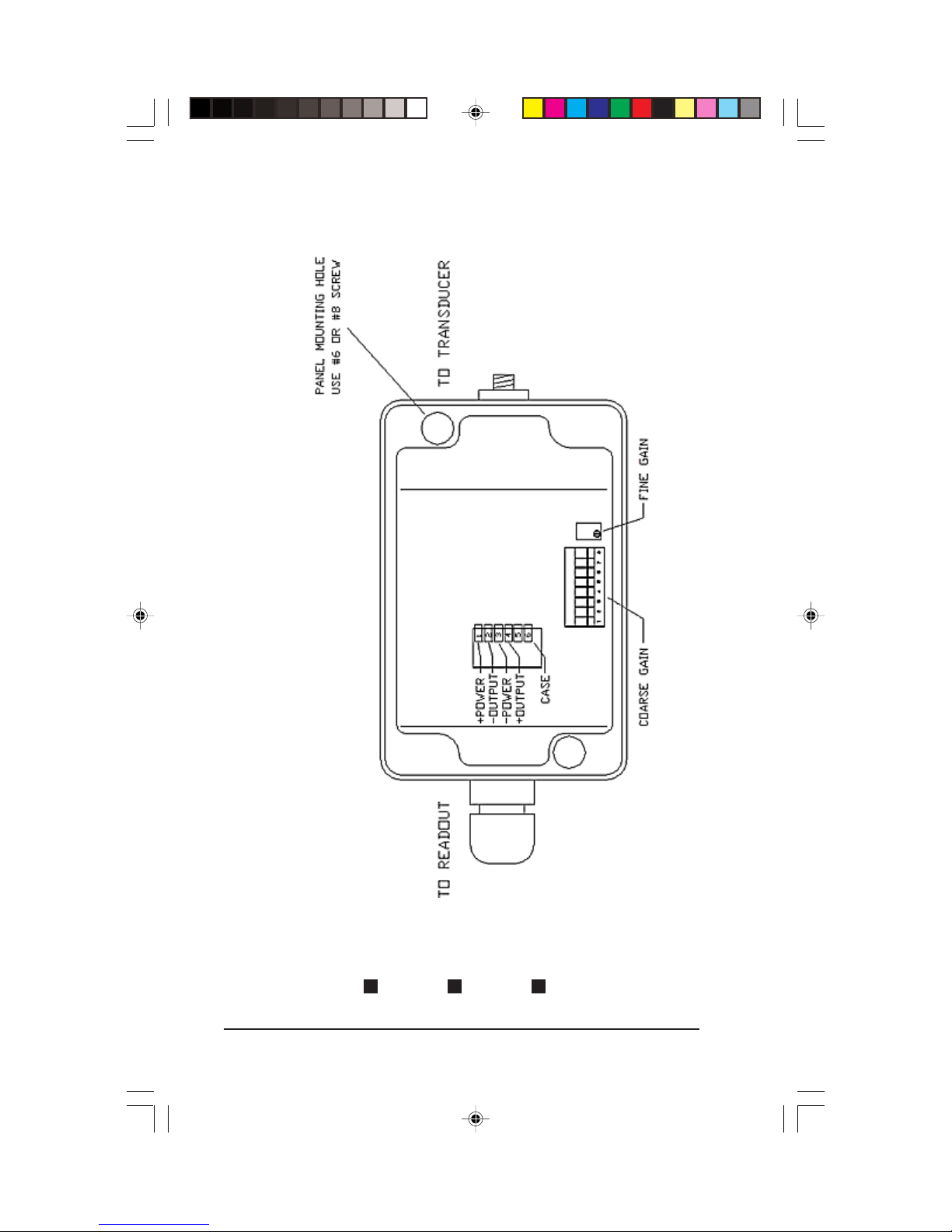
1.3 LAYOUT
008-0508-00 1-2
Figure 1-1. Layout of Inline Amplifier
Page 7
Chapter 2
INSTALLATION / SET UP
2.1 WIRING
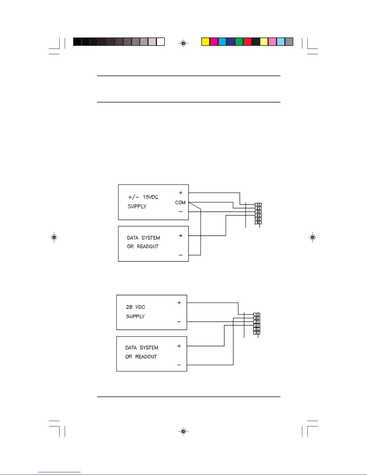
The Inline Charge amplifier can be powered from a + / - 15 volts DC or
a 24 to 32 volt single voltage supply. The following diagrams show the
wiring to each type of supply.
Cables should be stripped back 3 inches with the wires stripped and
tinned 1/2 inch. Connections to the terminal block are made by pressing
the orange levers and inserting the wires into the holes next to the levers.
The terminal block will accept wire up to AWG 20.
Figure 2-1. + / - 15 Volt Power Supply to Inline Wiring
Figure 2-2. 24 - 32 Single Voltage Supply To Inline
008-0508-002-1
Page 8
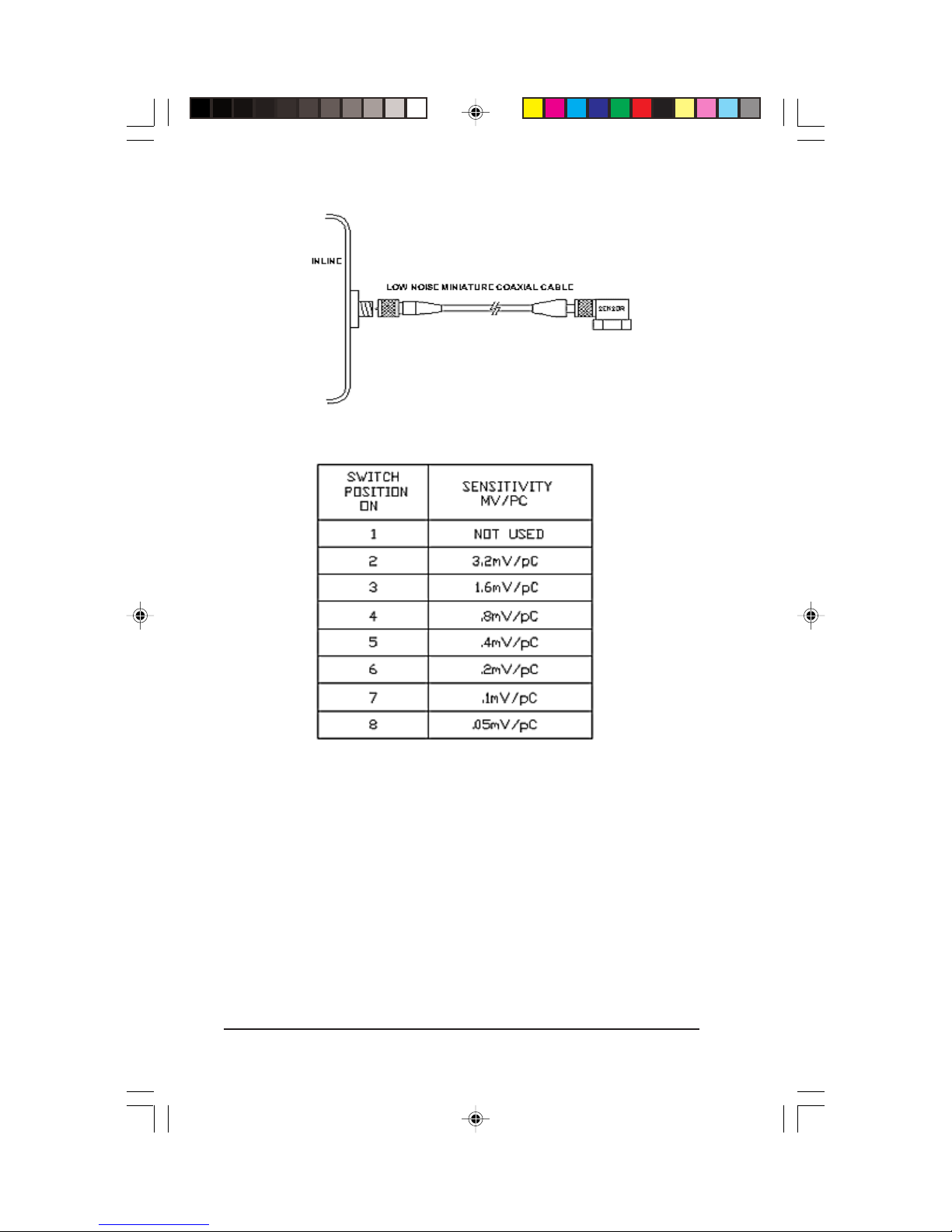
The connection to the sensor is thru a low noise miniature coaxial
cable. Cable length should be as short as possible to minimize noise.
Figure 2-2. Sensor to Inline Wiring
2.2 SENSITIVITY SELECT
Table 2-1. Coarse Gain Setup
Multiple switch combinations can be activated to attain additional sensitivities. For example, if 1mV/pC is desired then switches 4 and 6 would
be on. (.8V/pC+.2mV/pC=1mV/pC).
The factory default setting is 1mV/pC. DO NOT use the fine gain
adjustment potentiometer unless you are re-calibrating the charge
amplifier or if you are scaling the output to a known input. Adjusting the
fine gain potentiometer changes the sensitivities listed in table 2-1.
If the customer requests Sensotec to set-up the transducer and CA2 for
a single sensitivity, the coarse and fine gain adjustment should not be
altered. In this event the customer loses the flexibility of sensitivity
adjustment. Table 2-1 no longer applies.
008-0508-00
2-2
Page 9
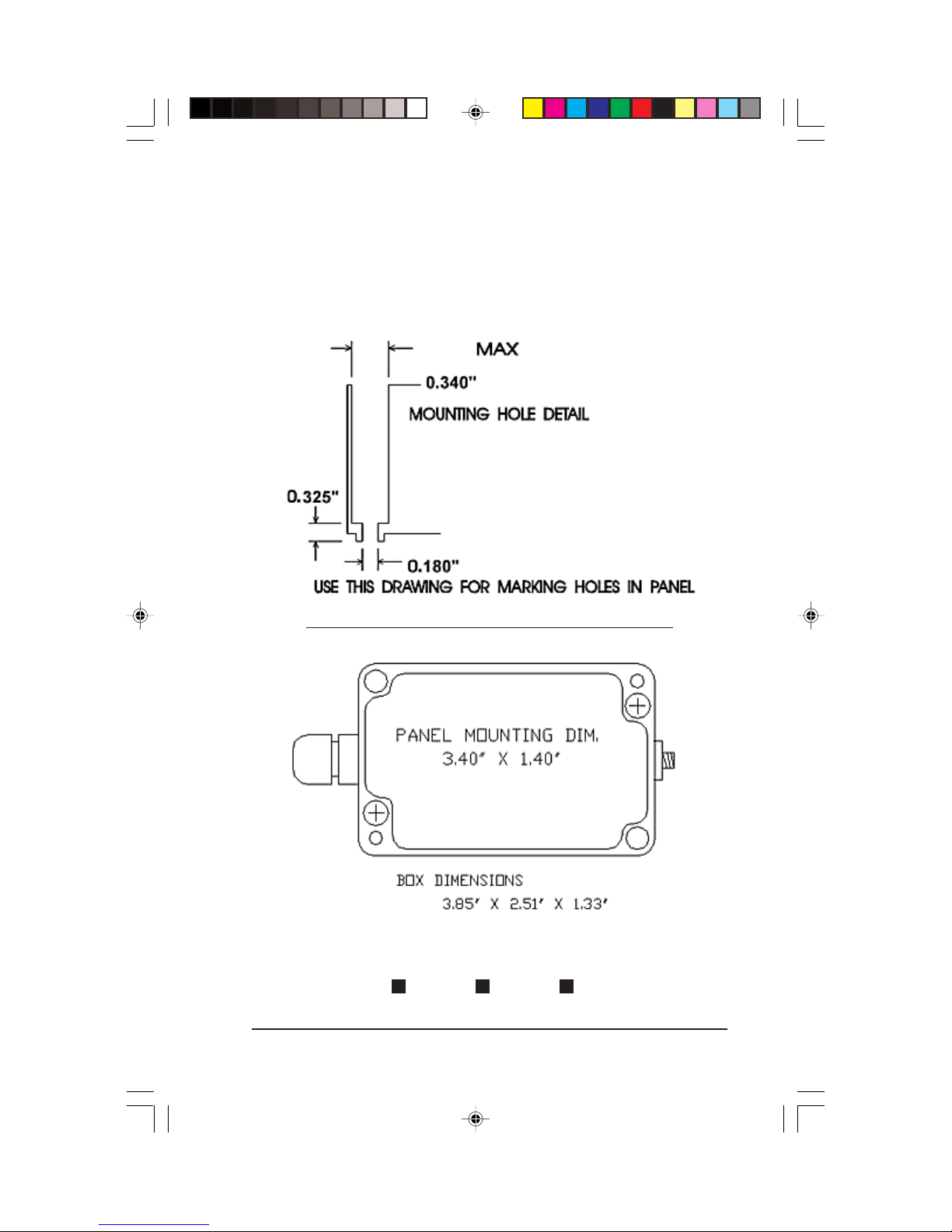
2.3 PANEL MOUNTING INFOMATION
The inline can be easily mounted to a panel by using the template in
Appendix A for marking the holes in the panel. The cover must be
removed to get access to the mounting holes. Use # 6 or # 8 screws for
mounting box to panel.
Actual size not shown. See Appendix A for Template.
Figure 2-3. Panel Mounting Layout
008-0508-002-3
Page 10

008-0508-00
Page 11

Chapter 3
CALIBRATION
3.1 CALIBRATION
Step 1. Apply power and allow unit to stabilize for 10 minutes.
Step 2. Calculate sensitivity switch based on desired mV/g or mV/lb
output. Use the following formulas:
Sensitivity = Desired mV/g
mV/pC Accelerometer Sensitivity pC/g
or
= Desired mV/lb
Load Cell Sensitivity pC/lb
EXAMPLES
Example # 1:
Sensitivity of the accelerometer = 100pC/g
Desired mV/g = 10
Sensitivity = 10 mV/g
mV/pC 100 pC/g
= .1mV/pC (switch 7)
Example # 2:
Sensitivity of load cell = 10pC/lb
Desired mV/lb = 20
Sensitivity = 20 mV/lb
mV/pC 10 pC/lb
= 2 mV/pC (switches 3 and 5)
008-0508-003-1
Page 12

Example # 3:
Sensitivity of accelerometer = 100 pC/g
Full scale g's = 50
Full scale output at 50g's = 5V
a.) 5V = .1V/g = 100 mV/g
50g
b.) Sensitivity = 100mV/g = 1mV/pC
mV/pC 100 pC/g (switches 4 and 6)
Example # 4:
Sensitivity of load cell = 10 pC/lb
Full scale lb's = 500
Full scale output at 500 lb's = 5V
a.) 5V = 10mV/lb
500 lb
b.) Sensitivity = 10 mV/lb = 1mV/pC
mV/pC 10 pClb
008-0508-00 3-2
Page 13
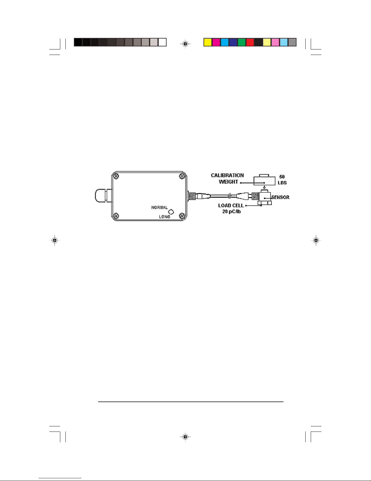
3.2 LONG TIME CONSTANT OPTION
If the long TC option was purchased there will be a front panel toggle
switch labeled LONG or NORMAL. Normal TC indicates the standard
time constant of 50 milliseconds. Long TC indicates a time constant of
2000 seconds. The long TC option is used to measure quasistatic (near
static) events and or to calibrate the sensor under static conditions.
During dynamic measurements reset the long TC toggle switch to
normal.
Quasistatic set-up examples:
Set sensitivity switches based on full-scale = 5V @ 50 lbs
1 ) Calculate mV/lb:
5V = .1V/lb = 100 mV/lb
50 lb
2 ) Calculate switch settings:
Sensitivity = 100 mV/lb = 5 mV/pC
20 pC/lb (switches 2, 3, 6)
3 ) Switch in normal mode.
4 ) Apply weight to load cell.
5 ) Toggle switch to long TC.
6 ) Quickly remove weight from load cell and note output voltage.
To insure accuracy the test must be performed as quickly as possible. The decay of the first 10% of the TC is linear. With a TC of
2000 seconds, we can conclude:
20 seconds = 1% accuracy
40 seconds = 2% accuracy
60 seconds = 3% accuracy
3-3
008-0508-00
Page 14

008-0508-00
Page 15

Chapter 4
WARRANTY / REPAIR POLICY
4.1 LIMITED WARRANTY ON PRODUCTS
Any of our products which, under normal operating conditions, proves
defective in material in workmanship within one year from the date of
shipment by SENSOTEC, will be repaired or replaced free of charge
provided that you obtain a return material authorization from SENSOTEC
and send the defective product, transportation charges prepaid with
notice of the defect, and establish that the product has been properly
installed, maintained, and operated within the limits of rated and normal
usage. Replacement product will be shipped F.O.B. our plant. The
terms of this warranty do not extend to any product or part thereof which,
under normal usage, has an inherently shorter useful life than one year.
The replacement warranty detailed here is the buyer’s exclusive remedy, and will satisfy all obligations of SENSOTEC whether based on
contract, negligence, or otherwise. SENSOTEC is not responsible for
any incidental or consequential loss or damage which might result from
a failure of any SENSOTEC product. This express warranty is made in
lieu of any and all other warranties, express or implied, including implied
warranty of merchantability or fitness for particular purpose. Any
unauthorized disassembly or attempt to repair voids this warranty.
4.2 OBTAINING SERVICE UNDER WARRANTY
Advanced authorization is required prior to the return to SENSOTEC.
Before returning the items, either write to the Customer Service Department c/o SENSOTEC, Inc., 2080 Arlingate Lane, Columbus, Ohio
43228, or call (800) 848-6564 with: 1) a part number; 2) a serial number
for the defective product; 3) a technical description* of the defect; 4) a nocharge purchase order number (so products can be returned to you
correctly); and 5) ship and bill addresses. Shipment to SENSOTEC shall
be at Buyer’s expense and repaired or replacement items will be shipped
F.O.B. our plant in Columbus, Ohio. Non-verified problems or defects
may be subject to an evaluation charge. Please return the original
calibration data with the unit.
008-0508-004-1
Page 16

4.3 OBTAINING NON-WARRANTY SERVICE
Advance authorization is required prior to the return to SENSOTEC.
Before returning the item, either write to the Customer Service Department c/o SENSOTEC, Inc., 2080 Arlingate Lane, Columbus, Ohio
43228, or call (800) 848-6564 with: 1) a model number; 2) a serial
number for the defective product; 3) a technical description* of the
malfunction; 4) a purchase order number to cover SENSOTEC’s repair
cost; and 5) ship and bill addresses. After the product is evaluated by
SENSOTEC, we will contact you to provide the estimated repair costs
before proceeding. Shipment to SENSOTEC shall be at Buyer’s expense and repaired items will be shipped to you F.O.B., our plant in
Columbus, Ohio. Please return the original calibration data with the unit.
4.4 REPAIR WARRANTY
All repairs of SENSOTEC products are warranted for a period of 90 days
from date of shipment. This warranty applies only to those items which
were found defective and repaired, it does not apply to products in which
no defect was found and returned as is or merely recalibrated. Out of
warranty products may not be capable of being returned to the exact
original specifications or dimensions.
* Technical description of the defect: In order to properly repair a
product, it is necessary for SENSOTEC to receive information specifying
the reason the product is being returned. Specific test data, written
observations on the failure and the specific corrective action you require,
is needed.
008-0508-00
4-2
Page 17
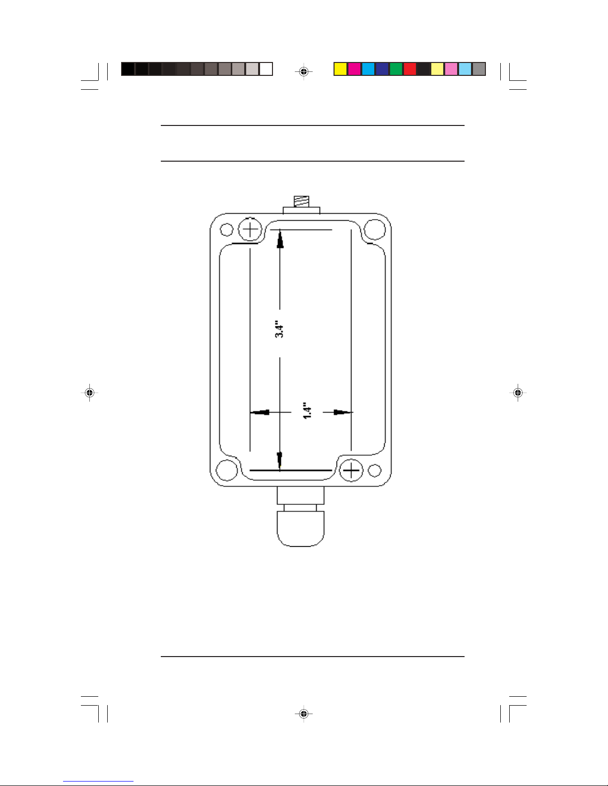
APPENDIX A
Figure A-1. Panel Mounting Template
008-0508-00A-1
 Loading...