


Sensormatic MV96P, MV19P, MV16P, MV99P, MV94P Manual
...English
Multivision® Pro
Installation and Operation
MV19p, MV16p,
MV94p, MV99p, MV96p
Part Number 8000-2135-01 REV B

Multivision® Pro
English
Notice
Copyright
The information in this manual was current when published. The manufacturer reserves the right to revise and improve its products. All specifications are therefore subject to change without notice.
Under copyright laws, the contents of this manual may not be copied, photocopied, reproduced, translated or reduced to any electronic medium or machine-readable form, in whole or in part, without prior written consent of Sensormatic Video Products Division.
© Copyright 1997 - 1999 Sensormatic Video Products Division
6795 Flanders Drive
San Diego, CA 92121
U.S.A.
Trademarks Robot® and Multivision® are registered trademarks of Sensormatic Video Products Division. Trademarked names are used throughout this manual. Rather than place a symbol at each occurrence, trademarked names are designated with initial capitalization. Inclusion or exclusion is not a judgment on the validity or legal status of the term.
ii
Installation and Operation Manual
WARNING: TO REDUCE RISK OF FIRE OR ELECTRIC
SHOCK, DO NOT EXPOSE THIS APPLIANCE TO
RAIN OR MOISTURE.
WARNING: DO NOT REMOVE COVER!
NO USER SERVICEABLE PARTS INSIDE.
REFER SERVICING TO QUALIFIED SERVICE PERSONNEL.
THE LIGHTNING FLASH WITH AN ARROWHEAD SYMBOL,WITHIN AN
EQUILATERAL TRIANGLE, INDICATES THE PRESENCE OF A SHOCK
HAZARD WITHIN THE PRODUCT’S ENCLOSURE.
Lithium Battery:
CAUTION: Danger of explosion if battery is incorrectly replaced. Replace only with the same or equivalent type recommended by the manufacturer. Dispose of used batteries according to the manufacturer's instructions.
Lithium Batterie
VORSICHT: Explosionsgefahr!
Batterie nur mit einem vom Hersteller empfohlenen gleichwertigen Typ ersetzen. Entsorgung muß nach Anweisungen des Herstellers erfolgen.
WARNING: This equipment has been tested and found to comply with the limits for a Class “A” digital device, pursuant to part 15 of the FCC Rules. These limits are designed to provide reasonable protection against harmful interference when the equipment is operated in a commercial environment. This equipment generates, uses and can radiate radio frequency energy and, if not installed and used in accordance with the instruction manual, may cause interference to radio communications. Operation of this equipment in a residential area is likely to cause harmful interference in which case the user will be required to correct the interference at their own expense.
Changes or modifications not expressly approved by the party responsible for compliance could void the user’s authority to operate the equipment.
This Class A digital apparatus meets all requirements of the Canadian Interference Causing Equipment Regulations.
Cet appareil numérique de la classe A respecte toutes les exigences du Règlement sur le matériel brouilleur du Canada.
iii

Multivision® Pro
CONGRATULATIONS
IMPORTANT
INFORMATION
You now own one of the many fine products manufactured by Robot. This product has been carefully inspected to rigid quality standards before shipment. With reasonable care, it will provide years of reliable performance.
Considering the investment, we know you will want to obtain the full performance capabilities engineered into your new Robot product. We recommend that you read this installation and operation manual thoroughly before attempting to operate this product.
Before proceeding, please read and observe all instructions and warnings contained in this manual. Retain this manual with the original bill of sale for future reference and, if necessary, warranty service.
When unpacking your new Robot product, check for missing or damaged items. If any item is missing, or if damage is evident, DO NOT INSTALL OR OPERATE THIS PRODUCT. Contact your Robot dealer for assistance.
FORYOUR PROTECTION
Purchase Date: _______________________________________
Serial Number: _______________________________________
Robot Dealer:
iv

|
Installation and Operation Manual |
|
TABLE OF CONTENTS |
CHAPTER 1 — FEATURES |
|
|
MULTIVISION PRO FEATURES........................... |
1 |
|
TECHNICAL OVERVIEW ..................................... |
2 |
|
Video Input and Output ........................................... |
2 |
|
Motion Detection ..................................................... |
2 |
|
Video Display ........................................................... |
2 |
|
Encoder Output ....................................................... |
3 |
|
Decoder Output ....................................................... |
3 |
|
CHAPTER 2 — FRONT & REAR PANELS |
|
|
THE FRONT PANEL ............................................ |
6 |
|
THE REAR PANEL .............................................. |
8 |
|
CHAPTER 3 — INSTALLATION |
|
|
REQUIRED CONNECTIONS ............................. |
10 |
|
Cameras 1–16 ....................................................... |
10 |
|
Main Mon ............................................................... |
10 |
|
Power ..................................................................... |
10 |
|
OPTIONAL CONNECTIONS .............................. |
10 |
|
Call Mon ................................................................ |
10 |
|
VCR In ................................................................... |
10 |
|
VCR Out ................................................................ |
11 |
|
S-VHS In ................................................................ |
11 |
|
S-VHS Out ............................................................. |
11 |
|
Alarm ..................................................................... |
11 |
|
Alarm Inputs ............................................................. |
11 |
|
Alarm Hold Input ....................................................... |
12 |
|
Alarm Output ............................................................ |
12 |
|
Motion Alarm Outputs ............................................... |
12 |
|
Autodetect VCR Speed ............................................. |
12 |
|
Remote .................................................................. |
12 |
|
Remote Control Panel Option ................................... |
12 |
|
SYSTEM CHECKOUT ........................................ |
13 |
|
Monitor Calibration ................................................ |
13 |
|
Camera Check ....................................................... |
14 |
|
Making a Test Tape ................................................ |
15 |
v

Multivision® Pro |
|
|
Table of Contents (continued) |
CHAPTER 4 — SETUP |
|
|
SETUP MENU SYSTEM .................................... |
16 |
|
Selecting a Menu ................................................... |
16 |
|
Positioning the Highlight ........................................ |
16 |
|
Setting an Option .................................................. |
16 |
|
SETUP MENUS ................................................. |
17 |
|
Menu 1 — System Time/Date ............................... |
17 |
|
Menu 2 — Day/Night Start Time ........................... |
18 |
|
Menu 3 — Toggle Options ..................................... |
18 |
|
Alarm Message Display ............................................ |
18 |
|
Alarm Message Latch ............................................... |
19 |
|
Video Loss Alarm ..................................................... |
19 |
|
Audible Alarm ........................................................... |
20 |
|
Alarm Input Polarity .................................................. |
20 |
|
Alarm Output Polarity ............................................... |
20 |
|
Pass-Thru Extrnl Alrms ............................................ |
21 |
|
Image Tenderizer ...................................................... |
21 |
|
Menu 4 — VCR Record Time ................................ |
21 |
|
Menu 5 — Alarm Duration ..................................... |
22 |
|
Menu 6 — Global Dwell ......................................... |
22 |
|
Menu 7 — Camera Titles ....................................... |
22 |
|
Motion Setup Screen ................................................ |
23 |
|
Motion Options ......................................................... |
24 |
|
ALRM (Alarm) ........................................................... |
24 |
|
SENSE (Sensitivity) .................................................. |
25 |
|
SIZE ......................................................................... |
25 |
|
DELAY ...................................................................... |
26 |
|
Working with Motion Targets ..................................... |
26 |
|
Menu 8 — Security Lock ....................................... |
27 |
vi

|
Installation and Operation Manual |
|
Table of Contents (continued) |
CHAPTER 5 — OPERATION |
|
|
LIVE MODE ........................................................ |
28 |
|
TAPE MODE ...................................................... |
28 |
|
Tape Playback With Two VCRs .............................. |
29 |
|
Tape Preview ......................................................... |
29 |
|
SETUP MODE.................................................... |
30 |
|
Viewing One Camera ............................................ |
30 |
|
Main Monitor ............................................................. |
30 |
|
Full Screen ............................................................... |
30 |
|
The 2x Zoom ............................................................ |
30 |
|
Zoom Control ............................................................ |
30 |
|
Call Monitor .............................................................. |
31 |
|
Viewing Multiple Cameras ..................................... |
31 |
|
Picture in Picture (PIP) ............................................. |
31 |
|
2x2 Format ............................................................... |
32 |
|
3x3 Format ............................................................... |
32 |
|
4x4 Format ............................................................... |
32 |
|
Sequencing Cameras ............................................ |
33 |
|
Videotape Operations ........................................... |
33 |
|
VCR Setup............................................................. |
33 |
|
Autodetect VCR Speed ............................................. |
34 |
|
Tape Recording ......................................................... |
34 |
|
Multicamera Recording ............................................. |
34 |
|
One Camera Recording ............................................ |
34 |
|
Tape Playback ........................................................... |
35 |
|
VCR Special Effects ................................................. |
35 |
vii

Multivision® Pro |
|
|
Table of Contents (continued) |
CHAPTER 6 — ALARMS |
|
|
MECHANICAL ALARMS .................................... |
36 |
|
MOTION ALARMS ............................................. |
36 |
|
Motion Alarm Status Table..................................... |
37 |
|
Alarm Counter ....................................................... |
38 |
|
Live Mode Alarm Response .................................. |
39 |
|
Tape Mode Live Alarm Response ......................... |
40 |
|
RECORDED ALARMS ....................................... |
41 |
|
VIDEO LOSS ALARMS ...................................... |
42 |
|
CHAPTER 7 — SPECIAL APPLICATIONS |
|
|
SIMULTANEOUS RECORD AND PLAY ............. |
43 |
|
MULTIPLEXED VIDEO TRANSMISSION ........... |
44 |
|
One-Way Video Transmission ................................ |
44 |
|
Two-Way Video Transmission ................................ |
44 |
|
APPENDIX A — ALARM CONNECTOR PIN |
|
|
ASSIGNMENTS ............................................. |
45 |
|
APPENDIX B — ALARM RECORDING |
|
|
CONTROL ...................................................... |
46 |
|
Uncontrolled Alarm Recording .............................. |
46 |
|
Controlled Alarm Recording .................................. |
47 |
|
APPENDIX C — IN CASE OF TROUBLE .......... |
48 |
viii

Installation and Operation Manual |
|
Table of Contents (continued) APPENDIX D — TECHNICAL |
|
SPECIFICATIONS .......................................... |
51 |
Operating Defaults ................................................ |
51 |
Video Format ......................................................... |
51 |
Video Level ............................................................ |
52 |
Alarm ..................................................................... |
52 |
Display ................................................................... |
52 |
Resolution.............................................................. |
52 |
Controls ................................................................. |
53 |
Connectors ............................................................ |
54 |
Electrical ................................................................ |
55 |
Physical Characteristics ........................................ |
55 |
Options .................................................................. |
55 |
ix

Multivision® Pro
FIGURES |
Figure 1 — Basic Multivision Pro System ............................ |
4 |
|
|
Figure 2 — Multivision Pro System with Two VCRs .............. |
4 |
|
|
Figure 3 — One-Way Multiplexed Video Transmission ......... |
5 |
|
|
Figure 4 — Multivision Pro System with |
|
|
|
Remote Control Panel ..................................................... |
5 |
|
|
Figure 5 |
— Front Panel Controls and Indicators .................. |
6 |
|
Figure 6 |
— Rear Panel Connectors ..................................... |
8 |
|
Figure 7 |
— Motion Setup Screen ....................................... |
23 |
|
Figure 8 — Motion Alarm Status Table ............................... |
37 |
|
|
Figure 9 |
— Alarm Counter ................................................. |
38 |
|
Figure 10 — Alarm Connector............................................ |
45 |
|
TABLES |
Table 1 — Alarm Connector Pin Assignments .................... |
45 |
|
|
Table 2 — Troubleshooting Guide ....................................... |
49 |
|
x
Installation and Operation Manual
SECURITY MEASURES NOTE: This page describes how to access security sensitive features. You may wish to remove this page from the
manual and place it in a secure place.
!  (Cut along this line)
Accessing Setup Menus |
The setup menu system is accessed from live mode. Press |
|
and hold the function button and press the zoom button |
|
(function+zoom). The first setup menu appears on screen. |
|
Use the zoom and arrow buttons to navigate through the menu |
|
system. See Chapter 4 — Setup for details. |
|
To exit the setup menu system, press function+zoom again. |
|
The menu disappears and the multiplexer resumes normal |
|
operation. |
The Security Lock Feature |
NOTE: Security Lock protects the multiplexer against |
|
unauthorized use by disabling all front panel controls |
|
except the FUNCTION and ZOOM buttons. Once |
|
engaged, Security Lock can be released only after |
|
placing the multiplexer in setup mode. |
To Engage or Release Security Lock
1.Select the operating mode in which the unit is to be locked.
2.Press and hold the function button and press the zoom button. The multiplexer enters setup mode and displays the first setup menu.
3.Press the zoom button repeatedly until the SECURITY LOCK menu appears.
4.Press the up or down arrow to engage (ON) or release (OFF) SECURITY LOCK.
5.Press function+zoom to exit setup mode. The multiplexer resumes normal operation.
xi

Multivision® Pro
Resetting the Multiplexer The multiplexer can be reset to the factory default state. Upon reset, all programmable features return to the factory settings.
The reset feature is normally used for diagnostic purposes but may be used to “start from scratch” during system setup.
To Reset the Multiplexer Press and hold the function button and press the up arrow button. A warning appears, asking if you want to reset the unit to factory defaults. Press live to cancel the reset. To continue the reset, press function+up arrow. The multiplexer resets and returns to the factory default state.
xii
Chapter 1 — Features |
1 |
|
|
Chapter 1 — Features
MULTIVISION PRO FEATURES
•High speed switching rate while recording.
•Automatic VCR speed detection feature lets the multiplexer match the VCR’s current recording speed.
•Full duplex operation allows video recording while viewing live video or playing back a tape.
•Simultaneous digital video motion detection using two 16x12 target motion detection grids for each video channel to set different options for day and night. Selectable target placement, object size, target sensitivity and alarm delay.
•Independent main and call monitor outputs allow simultaneous multicamera and full screen viewing.
•Dynamic Time Division (DTD) multiplexing allocates camera recording time based on picture motion content.
•Contact and TTL/CMOS alarm signals for VCR or other equipment.
•Alarm event counter with on-screen summary by camera.
•Motion alarm status table lists settings on-screen by camera for both day and night.
•Easy on-screen system setup. On-screen display includes date, time, alarm status, video loss and 10-character camera titles.
•ImageTenderizerdramaticallyreducesjitterassociatedwithhigh resolution compressed multicamera images.
•Improved Remote Control Panel option permits daisy chaining up to 16 multiplexers and changing the controlled multiplexer.
•Live or tape playback views include: full-screen, 2x zoom from full screen view, Picture-In-Picture (PIP), 2x2, 3x3 and 4x4.
•High resolution digital images enhanced by proprietary sharpening technique. Outstanding quality with a 512x464 (512x512 PAL) pixel display, 256 grays and 16 million colors.
•Rear panel termination switches can be set for each camera.
•Compatible with color and B&W video cameras or other NTSC/EIA (PAL/CCIR) standard video sources. Video synchronization is not required.
•Video inputs and outputs provided for both standard and Super VHS video cassette recorders (except B&W units).
•Nonvolatile program memory protects all programmable features against power loss.
2 |
Multivision® Pro Installation and Operation Manual |
|
|
TECHNICAL OVERVIEW
Video Input and Output
Motion Detection
The Multivision Pro series includes MV94p, MV99p, MV96p color multiplexers and MV19p, MV16p B&W multiplexers.
The multiplexer is available configured for either NTSC/EIA or PAL/CCIR video standard. The unit features video camera inputs with a passive looping output for each. Camera input impedance termination is set independently for each camera using switches on the back panel. Synchronizing or phasing cameras is not required.
Video recording and playback is supported by VCR connections for both composite and S-Video signal formats (color units only). The multiplexer automatically determines the format used during tape playback.
Two monitor outputs allow viewing live camera or videotaped pictures on standard monitors. The main monitor displays selected cameras in any available display format. The call monitor displays any alarm images or any live camera image full screen.
The multiplexer continuously monitors all camera inputs for motion. When motion is detected, the multiplexer increases how often that camera is recorded and displayed. If the motion alarm feature is ON, the multiplexer also alerts the operator with blinking panel LEDs. It also sounds an alarm tone and encodes camera images as ALARM if those setup menu options are ON. Motion detection options for day and for night can be set for each camera input using a 192-target (16 wide by 12 high) graphic overlay. This allows using more effective settings for alarm delay, object size, sensitivity and target position for the two time periods. You can also set motion alarms ON for night and OFF for day, or vice-versa.
Video Display The main monitor displays either live camera pictures or pictures from tape. The display is based on a 512x512x16
(512x464x16 NTSC/EIA) bit digital video memory containing two interlaced video fields. As many as 256 gray shades and 16 million colors can be displayed in six screen formats: full screen, 2x zoom, Picture-In-Picture (PIP), 2x2, 3x3 (9 and 16-camera models only) and 4x4 (16-camera models only).
Chapter 1 — Features |
3 |
|
|
Encoder Output
Decoder Output
The call monitor displays full screen images of cameras associated with alarms or images from any selected camera. It is based on switched analog camera video.
Color demodulation is based on luminance and color difference processing. Demodulation circuitry operates on a line by line basis and will correctly demodulate chroma information conforming to the NTSC (PAL) video standard.
A graphic generator with two interlaced bit mapped pages provides the alphanumeric and graphic overlays required for on-screen menus, camera titles and system messages.
The multiplexer video encoder produces a single video signal containing field by field samples from all camera inputs. The signal is provided in both composite and S-Video formats (color models only) for connection to a video recorder. Encoder operation is continuous and independent of display and decoder functions. All inputs are sampled in camera number order until motion is detected, when active cameras are sampled more often.
The encoder uses Vertical Interval Signaling (VIS) techniques to encode system information onto video output to the VCR. Time, date, camera title, camera number and alarm status information are placed on the 16 horizontal lines preceding the first active video line. This technique improves vertical synchronization recovery and improves graphics degraded by poor tape recorder performance.
The multiplexer decoder processes the video output by the VCR during playback, recovering the video from each camera originally recorded. The decoder digitizes the playback video and recovers the VIS information encoded onto each field. The recovered field is written to the video display memory if required for display.

4 |
|
|
|
Multivision® Pro Installation and Operation Manual |
||
|
|
|
|
|
|
|
|
|
|
|
|
|
|
|
|
|
|
|
|
|
|
|
|
|
|
|
|
|
|
|
|
|
|
|
|
|
|
|
|
|
|
|
|
|
|
|
|
|
Figure 1 — Basic Multivision Pro System
Figure 2 — Multivision Pro System with Two VCRs

Chapter 1 — Features |
5 |
|||||||||||||||
|
|
|
|
|
|
|
|
|
|
|
|
|
|
|
|
|
|
|
|
|
|
|
|
|
|
|
|
|
|
|
|
|
|
|
|
|
|
|
|
|
|
|
|
|
|
|
|
|
|
|
|
|
|
|
|
|
|
|
|
|
|
|
|
|
|
|
|
|
|
|
|
|
|
|
|
|
|
|
|
|
|
|
|
|
|
|
|
|
|
|
|
|
|
|
|
|
|
|
|
|
|
|
|
|
|
|
|
|
|
|
|
|
|
|
|
|
|
|
|
|
|
|
|
|
|
|
|
|
|
|
|
|
|
|
|
|
|
|
|
|
|
|
|
|
|
|
|
|
|
|
|
|
|
|
|
|
|
|
|
|
|
|
|
|
|
|
|
|
|
|
|
|
|
|
|
|
|
|
|
|
|
|
|
|
|
|
|
|
|
|
|
|
|
|
|
|
|
|
|
|
|
|
|
|
|
|
|
|
|
|
|
|
|
|
|
|
|
|
|
|
|
|
|
|
|
|
|
|
|
|
|
|
|
|
|
|
|
Figure 3 — One-Way Multiplexed Video Transmission
Figure 4 — Multivision Pro System with Remote Control Panel
6 |
Multivision® Pro Installation and Operation Manual |
|
|
Chapter 2 — Front & Rear Panels
The following is a brief overview of the multiplexer front and rear panels. Refer to Chapter 4 — Setup and Chapter 5 — Operation for a detailed discussion of multiplexer features and panel functions. Panel controls are illustrated below and each button is described by name and function.
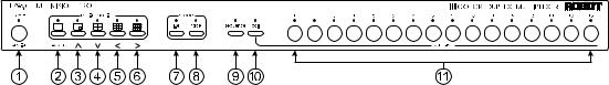
Figure 5 — Front Panel Controls and Indicators
THE FRONT PANEL Some front panel buttons have dual functions. The primary function is listed first, followed by the secondary function (shown
in parentheses). Indicator lights (LEDs) are above each button.
1.function (1 cam) — Used in combination with other buttons, it allows access to the system setup menus and other special functions described below.
To: |
Press: |
Display ALARM COUNTER |
function+left arrow |
Toggle time/date display |
function+right arrow |
Display
MOTION ALARM STATUS TABLE function+down arrow
Start 1 camera recording |
function (1 cam)+ |
|
a camera button |
2.zoom (full screen) — Press this button to view a 2x zoom of the selected camera. Press zoom again to go back to full screen view.
3.up arrow (PIP—Picture-In-Picture) — Displays the currently selected camera in the full screen format, inset with a 1/16 size picture of one other camera. The inset picture can be changed to a different camera or used for sequencing cameras. This button functions as an “up” control in the zoom and setup modes.
Chapter 2 — Front & Rear Panels |
7 |
|
|
4.down arrow (2x2) — Displays up to four cameras in the 2x2 format. Cameras not already displayed can be sequenced in the lower right window. This button functions as a “down” control in the zoom and setup modes. Press function+down arrow to display the
MOTION ALARM STATUS TABLE.
5.left arrow (3x3) — Displays up to nine cameras in the 3x3 format (9 and 16 camera models only). Cameras not already displayed can be sequenced in the lower right window. This button functions as a “left” control in the zoom and setup modes. Press function+left arrow to display the ALARM COUNTER.
6.right arrow (4x4) — Displays up to 16 cameras in the 4x4 format (16-camera models only). This button functions as a “right” control in the zoom and setup modes. Press function+right arrow to toggle the time/date display.
7.live — Displays the camera inputs in the selected format. It also turns on a row of motion targets in motion detection setup.
8.tape — Selects the VCR input for viewing. During tape playback, pressing the tape button displays recorded video in the selected format. During tape recording, this button permits monitoring images sent to the VCR. This button also turns off a row of motion targets during motion detection setup.
9.sequence — Starts automatic switching of cameras in the lower right corner of the screen (except in the full screen mode when it sequences full screen images). It also turns on all motion targets during motion detection setup.
10.call — Used before pressing a camera (1–16) button to select a camera for full screen display on the call monitor. This button also turns off all targets in motion detection setup.
11.camera (1–16) — Used to display cameras in the full screen format. Used with the call button to select a camera for full-screen display on the call monitor. During motion detection setup each camera button turns the corresponding motion target on the cursor line either off or on.
8 |
|
|
|
|
|
|
|
|
|
|
|
|
|
|
|
|
Multivision® Pro Installation and Operation Manual |
||||
|
|
|
|
|
|
|
|
|
|
|
|
|
|
|
|
|
|
|
|
|
|
|
|
|
|
|
|
|
|
|
|
|
|
|
|
|
|
|
|
|
|
|
|
|
|
|
|
|
|
|
|
|
|
|
|
|
|
|
|
|
|
|
|
|
|
|
|
|
|
|
|
|
|
|
|
|
|
|
|
|
|
|
|
|
|
|
|
|
|
|
|
|
|
|
|
|
|
|
|
|
|
|
|
|
|
|
|
|
|
|
|
|
|
|
|
|
|
|
|
|
|
|
|
|
|
|
|
|
|
|
|
|
|
|
|
|
|
|
|
|
|
|
|
|
|
|
|
|
|
|
|
|
|
|
|
|
|
|
|
|
|
|
|
|
|
|
|
|
|
|
|
|
|
|
|
|
|
|
|
|
|
|
|
|
|
|
|
|
|
|
|
|
|
|
|
|
|
|
|
|
|
|
|
|
|
|
|
|
|
|
|
|
|
|
|
|
|
|
|
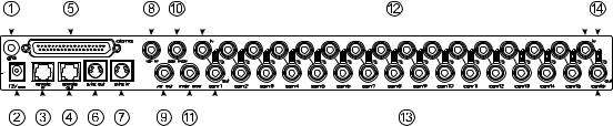
Figure 6 — Rear Panel Connectors (16-camera color model shown)
THE REAR PANEL 1. gnd (ground) — Use this ground post when connecting contact or TTL/CMOS compatible alarm devices. See
Alarms for details.
2.power — This 2.1 mm pin jack accepts the multiplexer power module plug or other center positive source of 12 VDC at 1.5 amperes.
3.remote in — This RJ11 connector allows remote control of the multiplexer using an optional remote control panel. If daisychaining either additional remote panels or multiplexers, remote out of the first unit is connected to remote in of the next unit.
4.remote out — This RJ11 connector allows daisychaining to another multiplexer. Up to 16 multiplexers can be connected to a remote panel, but only one multiplexer at a time can be addressed and controlled by the remote control panel.
5.alarms — This DB37-S connector allows alarm activation via contact closure or TTL/CMOS alarm inputs (up to 16). It includes the alarm hold input and alarm output relay contacts. There are also 16 motion alarm outputs, and an autodetect VCR speed feature which changes the rate that the multiplexer sends images to match the VCR recording speed.
6.s-vhs out — This S-type connector provides an S-Video signal to an S-VHS video recorder (color models only).
7.s-vhs in — This S-type connector accepts the S-Video playback signal from an S-VHS video recorder (color models only).
Chapter 2 — Front & Rear Panels |
9 |
|
|
8.vcr in — This BNC connector accepts the composite video playback signal from a VCR.
9.vcr out — This BNC connector provides a composite video signal to the record input of a VCR.
10.call mon — This BNC connector provides a composite video signal to the call monitor for the display of any alarm cameras (one at a time) or one live camera in the full screen format.
11.main mon — This BNC connector provides a composite video signal to the main monitor to display cameras in currently selected format.
12.cam in — These BNC connectors accept the composite video output of color or B&W cameras. Camera input impedance termination is selectable for each camera, using
the small switch on the back panel. Use 75 Ω for |
|
termination, or use ∞ |
if looping to other equipment. |
13.cam out — These BNC connectors provide looping camera video from the corresponding camera input.
14. ∞ or 75 Ω switch — These switches allow you to set impedance for each camera input. Set the switch to 75 Ω to terminate it, or set it to ∞ if looping to other equipment.
 Loading...