

Page 1
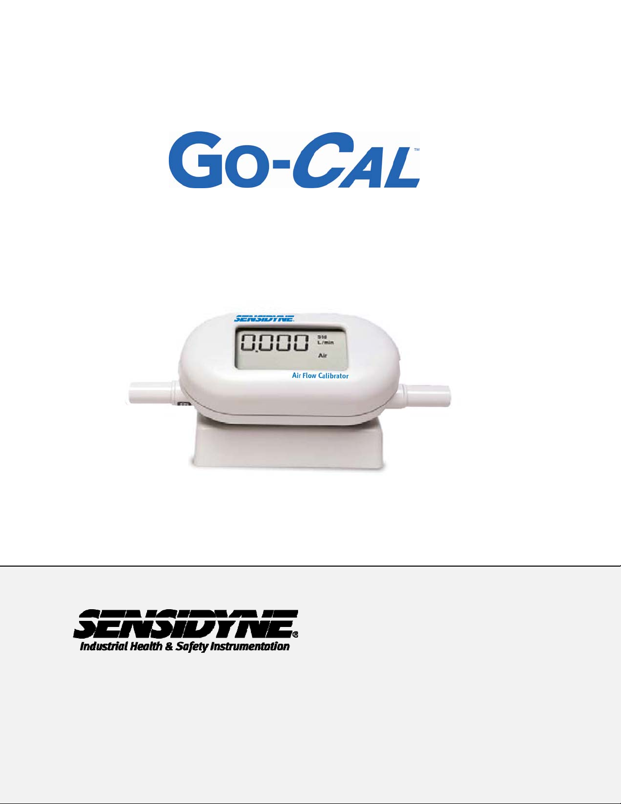
Air Flow Calibrator
User Manual
th
1000 1
(800) 451-9444 • +1 (727) 530-3602
www.Sensidyne.com • [email protected]
REF 360-0162-01 Rev. B
12
Circle North • Suite 100 • St. Petersburg, FL 33716 U.S.A.
Page 2

Page II
Sensidyne – GoCal Air Flow Calibrator User’s Guide
Quality Policy Statement
At Sensidyne, we are committed to providing products and services that
consistently meet customer needs and comply with all applicable
statutory and regulatory requirements.
Our products are designed and manufactured in accordance with ISO
9001:2008, EN 13980:2002, ATEX Directive 94/9/EEC, and IECEx.
Through ongoing review of our designs, supplier performance, and
customer feedback we strive to ensure continuous improvement.
All employees at Sensidyne share the responsibility to provide products
that are produced efficiently and economically representing the best
value to our customers.
We are committed to meeting or exceeding customer expectations in
everything we do.
Sensidyne, LP
© 2013 Sensidyne, LP Sensidyne Document No. 360-0162-01 (Rev B)
Page 3
Warning
Copyright
Sensidyne, LP / 2012 / All rights reserved.
Address
Sensidyne, LP,
This calibrator employs a heated platinum sensor.
!
!
It should not be used in the presence of flammable
or explosive gases or mixtures.
This calibrator is not a medical device under FDA
510k and in no situation should it be utilized for
human respiration measurements.
Sensidyne – GoCal Air Flow Calibrator User’s Guide
WARNING
Caution
Page 1
LIMITATION OF WARRANTY AND LIABILITY. Seller warrants that this product, under normal use and service as described in the operator's manual,
shall be free from defects in workmanship and material for a period of twenty-four (24) months, or the length of time specified in operator's manual,
from the date of shipment to the customer. This limited warranty is subject to the following exclusions:
a. Batteries and certain other components when indicated in specifications are warranted for a period of 90 days from the date of shipment to the
customer.
b. With respect to any repair services rendered, Seller warrants that the parts repaired or replaced will be free from defects in workmanship and
material, under normal use, for a period of 90 days from the date of shipment to the customer.
c. Seller does not provide any warranty on finished goods manufactured by others. Only the original manufacturer's warranty applies.
d. Unless specifically authorized in a separate writing by Seller, Seller makes no warranty with respect to, and shall have no liability in connection
with, any goods which are incorporated into other products or equipment by the Buyer. All goods returned under warranty shall be at the Buyer’s
risk of loss, Seller’s factory prepaid, and will be returned at Seller’s risk of loss, Buyer’s factory prepaid.
The foregoing is IN LIEU OF all other warranties and is subject to the conditions and LIMITATIONS stated herein. NO OTHER EXPRESS OR IMPLIED
WARRANTY OF FITNESS FOR PARTICULAR PURPOSE OR MERCHANTABILITY IS MADE.
THE EXCLUSIVE REMEDY OF THE USER OR PURCHASER, AND THE LIMIT OF THE LIABILITY OF SELLER FOR ANY AND ALL LOSSES,
INJURIES, OR DAMAGES IN CONNECTION WITH THIS PRODUCT (INCLUDING CLAIMS BASED ON CONTRACT, NEGLIGENCE, STRICT
LIABILITY, OTHER TORT, OR OTHERWISE) SHALL BE THE RETURN OF THE PRODUCT TO THE FACTORY OR DESIGNATED LOCATION AND
THE REFUND OF THE PURCHASE PRICE, OR, AT THE OPTION OF SELLER, THE REPAIR OR REPLACEMENT OF THE PRODUCT. IN NO
EVENT SHALL SELLER BE LIABLE FOR ANY SPECIAL, INCIDENTAL OR CONSEQUENTlAL DAMAGES. SELLER SHALL NOT BE
RESPONSIBLE FOR INSTALLATION, DISMANTLING, REASSEMBLY OR REINSTALLATION COSTS OR CHARGES. NO ACTION, REGARDLESS
OF FORM, MAY BE BROUGHT AGAINST THE SELLER MORE THAN ONE YEAR AFTER THE CAUSE OF ACTION HAS ACCRUED.
The purchaser and all users are deemed to have accepted the terms of this LIMITATION OF WARRANTY AND LIABILITY, which contains the
complete and exclusive limited warranty of Seller. This LIMITATION OF WARRANTY AND LIABILITY may not be amended or modified nor may any of
its terms be waived except by a writing signed by an authorized representative of Seller.
Sensidyne Document No. 360-0162-01 (Rev B) © 2013 Sensidyne, LP
Page 4

Page 2
Sensidyne – GoCal Air Flow Calibrator User’s Guide
Table of Contents
Quality Policy Statement..........................................................................................II
Warning ...................................................................................................................... 1
Table of Contents......................................................................................................2
SECTION ONE: Unpacking and Parts Identification ............................................. 3
SECTION TWO: Setting-Up......................................................................................5
2.1 Assembly Instructions for the Calibrators......................................................... 5
2.2 Supplying Power...............................................................................................6
2.3 Connecting Filter and Flow Tubes....................................................................6
SECTION THREE: Operation...................................................................................8
3.1 Overview .......................................................................................................... 8
3.2 ON/OFF Switch ................................................................................................8
3.3 Flow Rate Measurement ..................................................................................8
3.4 Setting Flow Rates and Calibrating Instruments............................................... 8
3.5 Dampening Module ..........................................................................................9
SECTION FOUR: Maintenance.............................................................................. 10
4.1 Flow Sensor ................................................................................................... 10
4.2 Re-certification................................................................................................10
4.3 Cases............................................................................................................. 10
4.4 Storage...........................................................................................................10
SECTION FIVE: Troubleshooting.......................................................................... 11
APPENDIX A: Specifications....................................................................................12
APPENDIX B: Factory Calibration and Service........................................................14
© 2013 Sensidyne, LP Sensidyne Document No. 360-0162-01 (Rev B)
Page 5
Sensidyne – GoCal Air Flow Calibrator User’s Guide
SECTION ONE: Unpacking and Parts Identification
Carefully unpack the instrument and accessories from the shipping container. Check the
individual parts against the list of components in Table 1. If any parts are missing or
damaged, notify Sensidyne immediately.
Table 1. List of Components (see figures 1-1 and 1-2)
Qty Item Description Part/Model
1 Calibrator 811-9916-01
Page 3
1 Filter
63 mm HEPA filter with 0.375 inch barbed fittings
1
1 Battery Pack 811-9917-03
1 Soft Carrying Case 811-9917-04
1 User’s Guide 360-0162-01
1 Dampening Module 811-9917-05
Table 2. Optional Accessories
Qty Item Description
1 AC Adapter
Tubing Kit
with connectors and battery pack mounting lugs
115 V, North America, ungrounded
811-9917-01
811-9917-02
Part/
Model
811-9918-01
100–240 V, NEMA 5-15 plug, grounded
100–240 V, Europlug, CEE 7/16, grounded
100–240 V, Great Britain, grounded, fused
100–240 V, Australia/NZ
Sensidyne Document No. 360-0162-01 (Rev B) © 2013 Sensidyne, LP
811-9918-02
811-9918-03
811-9918-04
811-9918-05
Page 6
Page 4
Sensidyne – GoCal Air Flow Calibrator User’s Guide
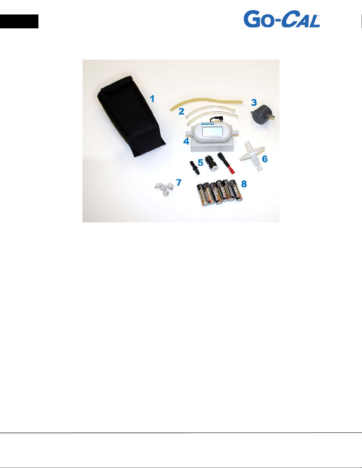
1. Soft-Sided Carrying Case
2. Latex Tubing
3. Dampening Module
4. Calibrator
5. Adapters
6. High-Efficiency Inlet Filter
7. Mounting Lugs
8. 6 AA-size Batteries
Figure 1 Kit Components
© 2013 Sensidyne, LP Sensidyne Document No. 360-0162-01 (Rev B)
Page 7
Sensidyne – GoCal Air Flow Calibrator User’s Guide
SECTION TWO: Setting-Up
2.1 Assembly Instructions for the Calibrators
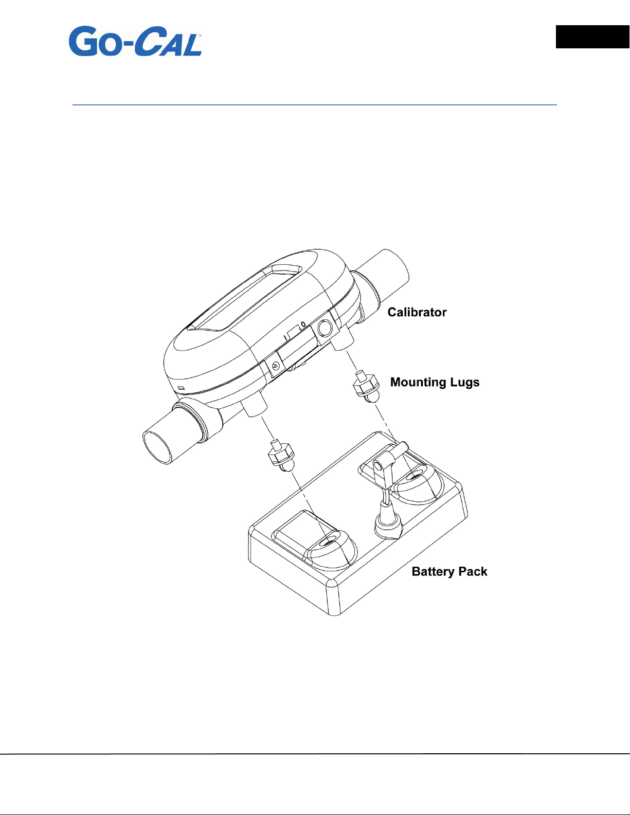
The calibrator can be quickly attached to the battery pack by screwing the mounting
lugs into the threaded holes in the base of the calibrator. The lugs should then be
placed over the receiving holes in the top of the battery pack and snapped gently into
place. Insert the connector from the battery pack to the receptacle in the back of the
calibrator. The calibrator is now ready to use.
Page 5
Figure 2-1 Calibrator Assembly
Sensidyne Document No. 360-0162-01 (Rev B) © 2013 Sensidyne, LP
Page 8
Page 6
Sensidyne – GoCal Air Flow Calibrator User’s Guide
2.2 Supplying Power
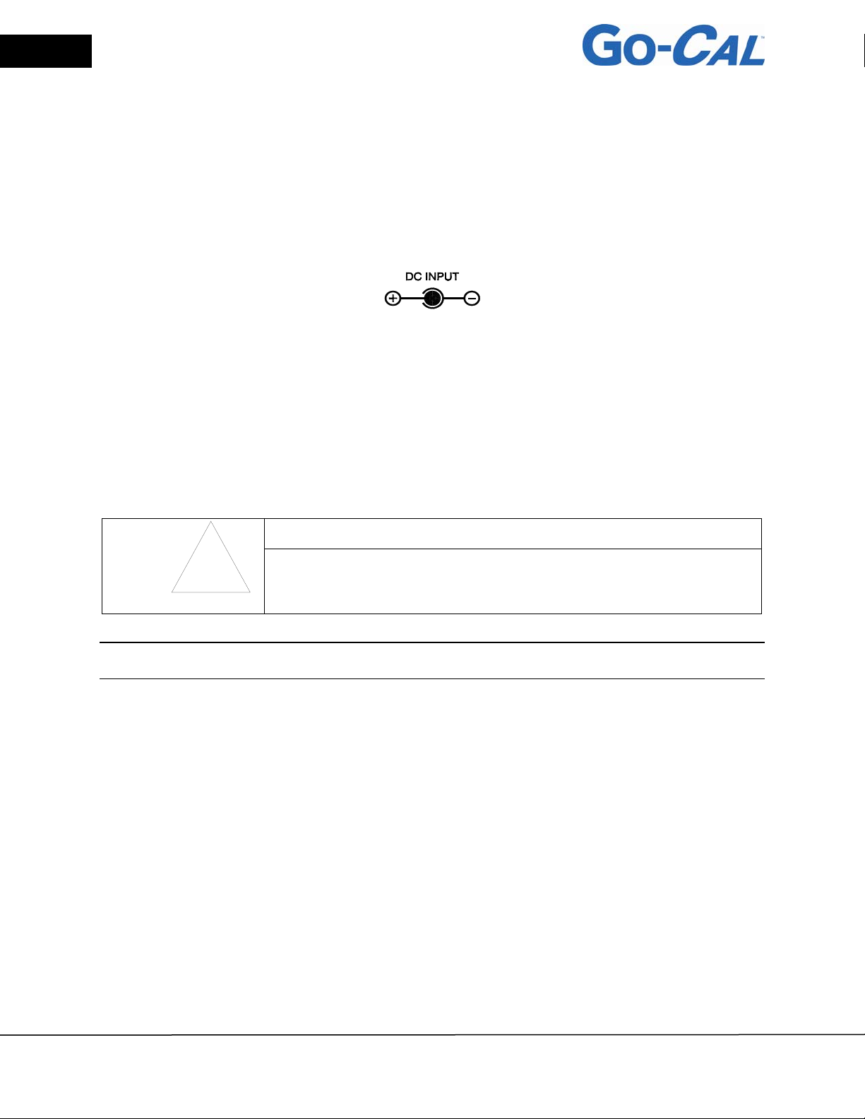
The calibrator can be powered in one of two ways: through the power jack using the
supplied 811-9917-03 battery pack or using an optional AC adapter. The DC power
input connector is shown below along with the power requirements.
Power Supply: 7.5 VDC ± 1.5 V, 300 mA maximum
2.3 Connecting Filter and Flow Tubes
The calibrator has a thermal sensor exposed to the air flow that must be protected from
foreign matter and particles. Sensidyne supplies a filter that should be connected to the
inlet of the calibrator; however, any filter will work as long as it has a minimum efficiency
of 99.9%.
Caution
Always use a filter on the inlet of the calibrator. Failure to filter the air
!
Note: Flow direction is identified by the large arrow printed on the bottom side of the calibrator and on
the bottom of the battery pack.
Attach the filter to the inlet of the calibrator using supplied tubing and/or adapters. Connecting a tube to
the outlet of the calibrator will create back pressure. See Appendix A for calibrator accuracy specifications
when operating at various pressures. In general, minimize back pressure on the calibrator by using
shorter lengths of tubing to maintain highest level of accuracy.
flow may change the calibration and/or permanently damage the
sensor.
© 2013 Sensidyne, LP Sensidyne Document No. 360-0162-01 (Rev B)
Page 9
Sensidyne – GoCal Air Flow Calibrator User’s Guide
Page 7
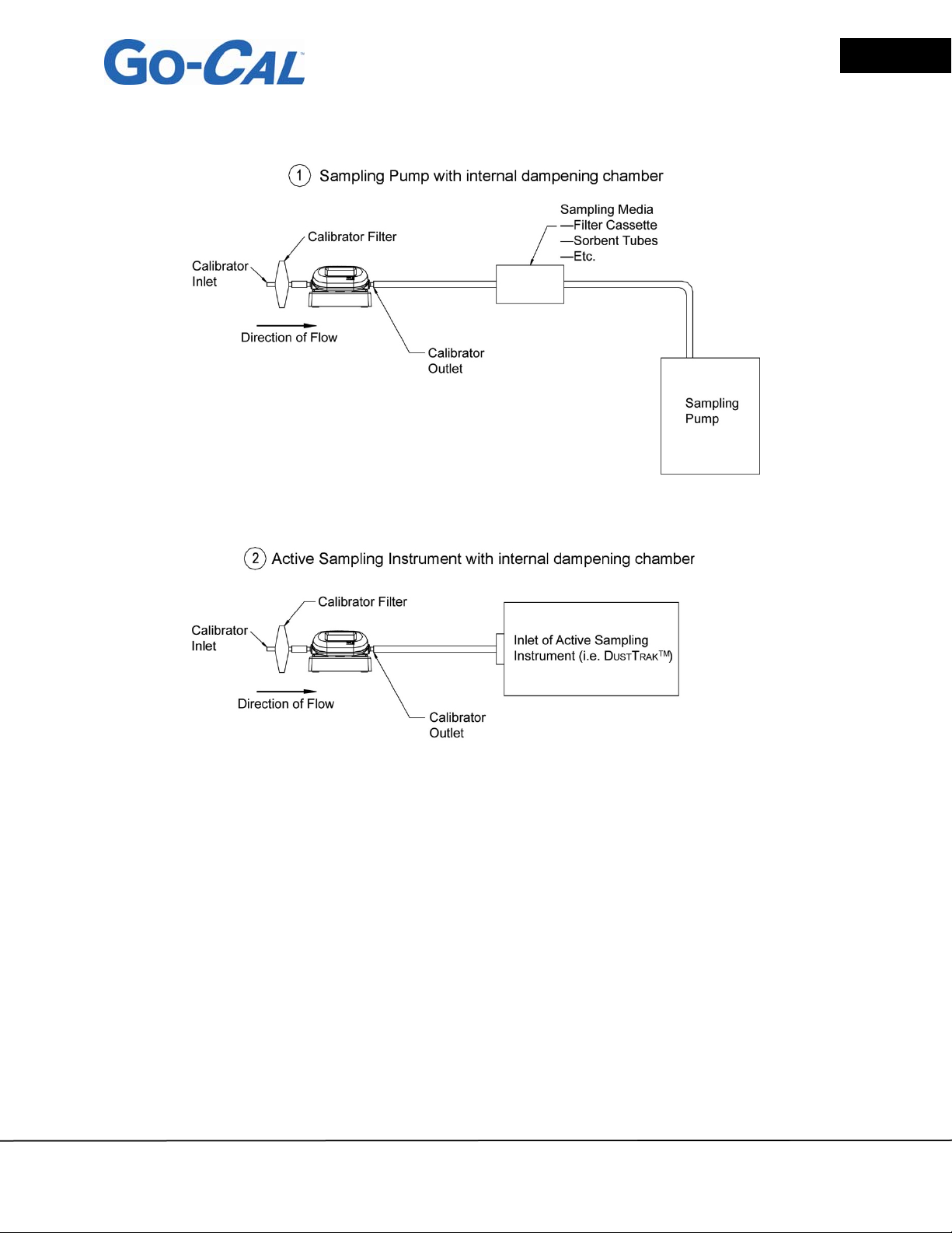
Figure 2-2 Typical Setup Configurations
A dampening module is available for calibrating sampling pumps that do not incorporate
an internal pulsation dampener. Use the 6 in. (15 cm) tubing to connect the dampening
chamber in line between the GoCal Calibrator and the instrument. For best results,
position Dampening Module with openings to the side, off the work surface.
Sensidyne Document No. 360-0162-01 (Rev B) © 2013 Sensidyne, LP
Page 10

Page 8
Sensidyne – GoCal Air Flow Calibrator User’s Guide
SECTION THREE: Operation
3.1 Overview
The calibrator measures volumetric flow rate inside the flow tube. All measurements
are NIST traceable.
3.2 ON/OFF Switch
Slide the switch to the ON position. The LCD displays volumetric flow in units of liters
per minute (L/min).
3.3 Flow Rate Measurement
Flow rate data will be displayed through the LCD.
Volumetric flow is displayed in units of liters per minute (L/min).
3.4 Setting Flow Rates and Calibrating Instruments
The calibrator may be used to set flow rates and calibrate sampling pumps or other
instruments which draw an active flow sample. Be sure to follow all instrument
manufacturer’s flow setting and calibration procedures.
1. Start up the calibrator and let it warm up for 1 minute prior to setting any flow rates
or conducting any calibrations.
2. Configure your sampling with the desired sampling media and sampling train to be
used.
3. Connect the outlet of the calibrator to the inlet of the sample media (used with
sampling pumps) or to the inlet of the active sampling instrument using the tubing
supplied.
4. Follow the instrument manufacturer’s flow setting and/or calibration procedures.
The volumetric flow in units of liters per minute (L/min) will be continuously
displayed on the LCD of the calibrator.
© 2013 Sensidyne, LP Sensidyne Document No. 360-0162-01 (Rev B)
Page 11
Sensidyne – GoCal Air Flow Calibrator User’s Guide
3.5 Dampening Module
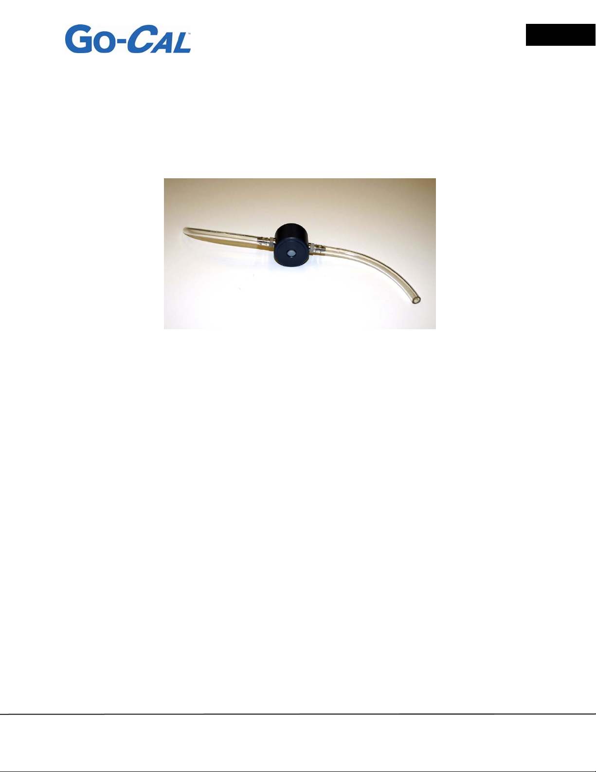
The Dampening Module is included for use with systems that do not have internal
dampening chambers. The Dampening Module (P/N 811-9917-05) can be added in
line between the end of the sampling train and the calibrator. The Dampening Module
reduces flow pulsation with insignificant affect on flow rate or back pressure.
Page 9
Figure 3-1 Dampening Module with Tub ing Attached
All diaphragm pumps produce flow pulsations during operation. Most commercially
available 3 L/min and 5 L/min sampling pumps are designed with internal dampening
chambers to minimize flow pulsations.
Some common air sampling instruments that may not have internal flow pulsation
dampening chambers are listed below. Contact your instrument manufacturer if you
have questions. This list is just an example and is not intended to be all inclusive.
Low flow personal sampling pumps
Confined space meters
Photometers
Optical Particle Counters (OPCs)
Condensation Particle Counters (CPCs)
Photo Ionization Detectors (PIDs)
Flame Ionization Detectors (FIDs)
Sensidyne Document No. 360-0162-01 (Rev B) © 2013 Sensidyne, LP
Page 12
Page 10
Sensidyne – GoCal Air Flow Calibrator User’s Guide
SECTION FOUR: Maintenance
4.1 Flow Sensor
Periodically inspect the flow sensor by looking into the outlet of the calibrator. Remove
dust, particles and fibers from the sensor with clean, dry, low pressure compressed air.
The flow sensor may break if touched. Never run liquids through the calibrator and
never touch the sensor with a brush. Dust or other deposits on the flow sensor will
degrade the flow accuracy.
Caution
The calibrator must be switched off for
!
cleaning. Only use clean, dry, low pressure
compressed air when attempting to remove
contamination from the sensor.
4.2 Re-certification
To maintain a high degree of confidence in the measurements made by the calibrator,
Sensidyne recommends that the instrument be returned to Sensidyne every 12 months
for re-certification. The calibrator will be recalibrated and returned with a certificate of
calibration to US National Institute of Standards Technology (NIST) traceable
standards.
4.3 Cases
If the instrument case or storage case needs cleaning, wipe it off with a soft cloth dipped
in isopropyl alcohol or mild detergent. Never submerge the calibrator or allow liquids to
enter the flow tube.
4.4 Storage
When storing the calibrator, always cover the ends of flow tubes with the caps provided
to prevent dust or other foreign matter from entering the tube.
© 2013 Sensidyne, LP Sensidyne Document No. 360-0162-01 (Rev B)
Page 13
Sensidyne – GoCal Air Flow Calibrator User’s Guide
SECTION FIVE: Troubleshooting
Table 3 lists the symptoms, possible causes, and recommended solutions for common
problems encountered with calibrator. If the symptom is not listed, or if none of the
solutions solves the problem, please contact Sensidyne at 1-800-451-9444, extension
781 or 727-530-3602, extension 781 or [email protected].
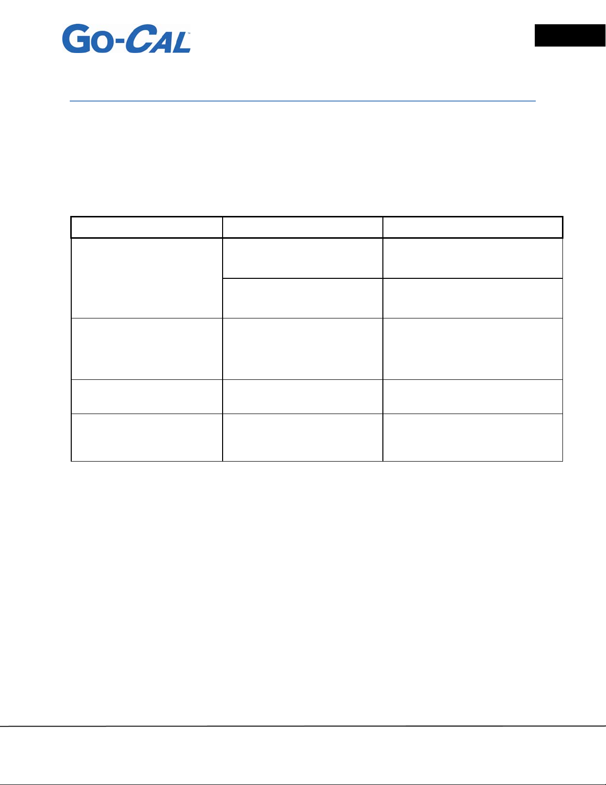
Table 3. Troubleshooting
Symptom Possible Causes Corrective Action
Unit not switched on Switch on the unit
Page 11
No display
Temperature reads high at
low or zero flows
Flow readings fluctuate
greatly
Display shows flows overrange with no flow passing
through flow tube
No power to instrument Check power connection
Temperature sensor is
being heated from the flow
sensor
The flow is fluctuating Improve inlet conditions or
The sensor may be
damaged or broken
The temperature value will track
the actual air temperature once
the flow rate through the
calibrator exceeds 1 Std L/min
increase display averaging time
Return calibrator to Sensidyne
for service
Sensidyne Document No. 360-0162-01 (Rev B) © 2013 Sensidyne, LP
Page 14

Page 12
Sensidyne – GoCal Air Flow Calibrator User’s Guide
APPENDIX A: Specifications
Specifications*
Flow Measurement
Measurement Range
Accuracy
0.01 to 20 L/min
±2% of reading or 0.005 std. L/min, whichever is greater at
standard conditions (21.1°C and 101.3 kPa)
See notes 1 through 5 below.
Instrument Temp. Range
Operation, Ambient
Storage, Ambient
Physical Dimensions
External Dimensions
Tube Adapters
(Inlet & Outlet)
Weight
Flow Body Material
Warm-up Time 1 min
Power Battery pack
0 to 50°C
-20 to 60°C
5 in. × 2 in. × 1.25 in.
(12.7 cm × 5 cm × 3.2 cm)
0.375 inch O.D. straight
1.7 lbs (0.8 kg)
Polycarbonate
7.5 VDC ± 1.5 V
, 300 mA maximum
Notes:
1 Accuracy stated at standard conditions of 21.1°C and 101.3 kPa.
2 Accuracy stated with air temperature and flow body temperature within ±10°C of one another.
3 Accuracy stated measuring dry air (less than 10% R.H.).
4 Includes ±0.5% of reading repeatability.
5 Volumetric flow rate is calculated from the mass flow measurement. Add an additional 0.25% of reading to the
flow accuracy to account for the uncertainty in measuring air temperature and pressure.
*Specifications subject to change without notice.
© 2013 Sensidyne, LP Sensidyne Document No. 360-0162-01 (Rev B)
Page 15
Sensidyne – GoCal Air Flow Calibrator User’s Guide
Page 13
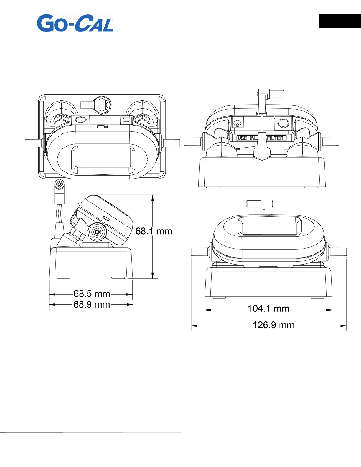
Figure A Unit Dimensions
Sensidyne Document No. 360-0162-01 (Rev B) © 2013 Sensidyne, LP
Page 16

Page 14
Sensidyne – GoCal Air Flow Calibrator User’s Guide
APPENDIX B: Factory Calibration and Service
Sensidyne, LP
1000 112
St, Petersburg, Florida 33716
U.S.A.
800-451-9444
+1 727-530-3602
+1 727-539-0550 [Main fax]
+1 727-538-0671 [Service fax]
[email protected]
www.Sensidyne.com
th
Circle North, Suite 100
© 2013 Sensidyne, LP Sensidyne Document No. 360-0162-01 (Rev B)
Page 17

Sold by:
Sensidyne, LP
1000 112th Circle North, Suite 100
St, Petersburg, Florida 33716
U.S.A.
800-451-9444 • +1 727-530-3602 • [fax] +1 727-539-0550
www.Sensidyne.com • [email protected]
Authorized EU Representative
Schauenburg Electronic Technologies GmbH
Weseler Str. 35 · 45478
Mülheim-Ruhr Germany
+49 (0) 208 9 99 10 • +49 (0) 208 5 41 10 [fax]
www.schauenburg.com • [email protected]
Sensidyne Document No. 360-0162-01 (Rev B) © 2013 Sensidyne, LP
Page 18

1000 112
th
Circle North • Suite 100 • St. Petersburg, FL 33716 U.S.A.
(800) 451-9444 • +1 (727) 530-3602
www.Sensidyne.com • [email protected]
 Loading...