

Page 1
SL Headmic 1
Instruction manual
Page 2

Page 3

Safety instructions
Safety instructions
• Please read this instruction manual carefully and completely
before using the product.
• Make this instruction manual easily accessible to all users at all
times.
• Always include this instruction manual when passing the product on to third parties.
• Liquid entering the housing of the product can cause a short-circuit and damage the electronics. Keep all liquids away from the
product.
• Do not expose the product to extreme temperatures.
• Use the product with care and store it in a clean, dust-free environment.
• Only use attachments, accessories or spare parts specified by
Sennheiser.
Intended use
Intended use includes:
• having read these instructions, especially the chapter “Safety
instructions”,
• using the product within the operating conditions and limitations described in this instruction manual.
• never opening the product. If products are opened by customers
in breach of this instruction, the warranty becomes null and
void.
“Improper use” means using the product other than as described
in these instructions, or under operating conditions which differ
from those described herein.
3
Page 4

SL Headmic 1
SL Headmic 1
The SL Headmic 1 is a high-quality omni-directional condenser
headset microphone designed for professional “hands free” applications. Its adjustable neckband is visually unobtrusive and very
comfortable to wear. The SL Headmic 1 is available in black and
beige.
Features
• Individually adjustable to all head sizes
• Thin microphone boom, interchangeable
• Microphone boom can be attached to the left or right side
• Microphone boom is adjustable in length
• Modular overall system, i.e. all system components are easily
interchangeable
Package contents
•1 SL Headmic 1
• 1 connection cable
• 1 MZC 2 frequency response cap
• 1 SL MZW 1 windshield
• 1 soft case
• 1 instruction manual
4
Page 5
Putting into operation
Putting into operation
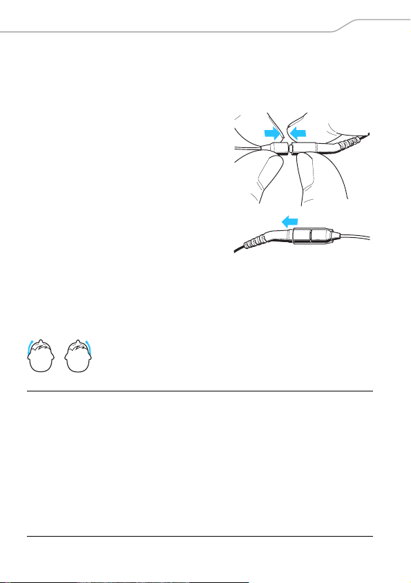
To connect the cable to the headset microphone:
왘 Plug the connector into the socket.
왘 Slide the silicone tube onto the
connector.
The microphone can be worn on the left or right side of the mouth.
If you do not want to change sides, continue on page 7.
Changing the microphone position (left/right)
The neckband has a total of five clips which are
designed so that the microphone boom can be
worn on either side of the mouth.
NOTICE Damage to the microphone boom
The microphone boom can break or be impaired in
its function when you bend or turn it. Also avoid frequent alternate bendings close to the microphone
head as this can also damage the microphone boom
and possibly reduce the adjustability of the microphone.
왘 Only adjust the microphone boom as described in
this chapter.
5
Page 6
Putting into operation
90°
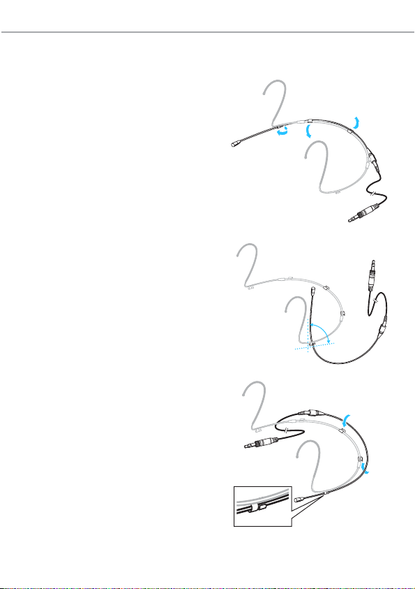
To remove the microphone boom:
왘 First remove the microphone
boom from the two clips and
.
왘 By turning the microphone
boom, remove it from the third
clip .
To reattach the microphone boom:
왘 First attach the end of the
microphone boom where the
microphone head is fitted to
the clip on the desired side
of the neckband.
왘 Press the microphone boom
into the two clips and .
6
Page 7

Putting into operation
2–3 cm
Adjusting the microphone boom and the neckband
For best possible comfort and optimum fit of the headset microphone, the neckband and the microphone boom have to be
adjusted to properly fit your head.
NOTICE Damage to the microphone boom
The microphone boom can break or be impaired in
its function when you bend or turn it.
Positioning the microphone towards the corner of the mouth
To individually position the microphone:
왘 Push the microphone boom in
backwards or forwards in the clips
so that the microphone is positioned 2 to 3 cm from the corner
of the mouth. The further away
the microphone is from the
mouth, the less treble is picked
up.
Adjusting the neckband
The neckband is adjustable in width
and ensures an optimum fit.
왘 Change the length of the neck-
band by moving the ear hooks
until a snug but comfortable fit is
achieved.
7
Page 8

Putting into operation
Using the frequency response caps
The MZC 2 frequency response cap allows you
to adjust the microphone’s sensitivity in the presence area. The MZC 2 gives a treble boost of 4 dB
(see “Frequency response curve” on page 15).
Use this cap if the microphone cannot be positioned close to the mouth, if the sound is too muffled or if you want to increase the speech intelligibility.
왘 Slip the MZC 2 frequency response cap onto
the microphone until it locks into place with an
audible click.
An additional frequency response cap (MZC 1) is
available as accessory. The MZC 1 ensures a treble
boost of 2 dB.
왘 Slip the MZC 1 frequency response cap onto
the microphone until it locks into place with an
audible click.
8
Page 9

Putting into operation
Using the windshield
The SL MZW 1 windshield attenuates annoying wind noise by 10 dB.
왘 Slip the SL MZW 1 windshield onto the
MZC 2 frequency response cap .
Attaching the connection cable to clothing
The MZQ 02 cable clip is available as accessory.
왘 Press the tube of the connection cable into the
cable grip of the MZQ 02 cable clip.
왘 Attach the cable clip to the rear of your collar.
왘 Run the connection cable under your clothing.
9
Page 10

Putting into operation
Connection cable with 3.5 mm jack plug
The cable is suitable for use with Sennheiser bodypack transmitters with 3.5 mm jack socket. For wired applications, the headset
microphone can be used with the intelligent MZA 900 P phantom
power adapter.
왘 Lock the jack plug for safe operation.
10
Page 11

Care and maintenance
Care and maintenance
NOTICE Liquids can damage the electronics of the device
Liquids entering the housing of the device can cause
a short-circuit and damage the electronics.
왘 Only use a soft, slightly damp cloth to clean the
device.
Cleaning the frequency response caps
왘 To clean or replace the frequency response cap, carefully pull it
from the capsule.
왘 Moisten a small brush (bristle brush or toothbrush) with iso-
propyl alcohol.
왘 Carefully brush off the frequency
response cap.
왘 Allow the frequency response cap to air
dry for approx. 1 hour so that the
remaining isopropyl alcohol can evaporate.
왘 Reattach the frequency response cap
to the capsule so that it locks into place
with an audible click.
11
Page 12

Care and maintenance
Cleaning the contacts of the connection cable
Over time, salt deposits from sweat can build up on the connector
and the socket. Clean the connector and the socket as follows
using standard isopropyl alcohol.
To loosen the connection:
왘 Slide the silicone tube aside.
왘 Insert your fingernail into the
join.
왘 Pull the connector and the socket
apart as shown.
왘 Moisten a small brush (bristle
brush or toothbrush) with isopropyl alcohol.
왘 Carefully brush off the connector
and the socket and remove the
salt deposits.
12
Page 13

Care and maintenance
왘 Rinse the connector and the socket with isopropyl alcohol to
remove the remaining salt deposits.
왘 Dry the connector and the socket using a soft cloth or a small
piece of cotton wool and carefully tap them off.
왘 Allow the connector and the socket to air dry for approx. 1 hour
so that the remaining isopropyl alcohol can evaporate.
왘 Slide the silicone tube onto the connector.
왘 Connect the connector to the socket.
13
Page 14

Specifications
Specifications
Frequency response 20 to 20,000 Hz ± 3 dB
Pick-up pattern omni-directional
Nominal impedance
(at 1 kHz)
Min. terminating impedance 4.7 kΩ
Sensitivity 5 mV/Pa ± 3 dB
Diameter of mic capsule 3.3 mm
Max. sound pressure level 143 dB
Equivalent noise level 27 dB (A)
Supply current approx. 240 μA
Power supply 4.5
Temperature range
Operation
Storage
Relative air humidity max. 95 %
Cable length 1.6 m
Diameter of boom arm 1.1 mm
Connector 3.5 mm jack plug
Weight (without cable) approx. 7 g
1 kΩ
to 15 V
–10 °C to +50 °C
–20 °C to +70 °C
14
Page 15

Specifications
0°
5
10
15
20
25
dB
30°
60°
90°
30°
60°
90°
120°
150°
180°
150°
120°
2000 Hz
4000 Hz
8000 Hz
16000 Hz
125 Hz
250 Hz
500 Hz
1000 Hz
0
Polar diagram
50
20
0°; 1 m with MZC 2 frequency response cap
90°; 1 m
Frequency response curve
dBv
- 35
- 40
- 45
- 50
- 55
- 60
- 65
- 70
100
200
500
1000 2000
5000
10000
20000
Hz
15
Page 16

Manufacturer Declarations
Manufacturer Declarations
Warranty
Sennheiser GmbH & Co. KG gives a warranty of 24 months on this
product.
For the current warranty conditions, please visit our website at
www.sennheiser.com or contact your Sennheiser partner.
In compliance with the following requirements
• WEEE Directive (2012/19/EU)
Please dispose of this product by taking it to your local
collection point or recycling center for such equipment.
CE Declaration of Conformity
• RoHS Directive (2011/65/EU)
• EMC Directive (2004/108/EC)
The declaration is available at www.sennheiser.com.
In compliance with
Europe
China
Australia/New Zealand
16
EMC EN 55103-1/-2
RoHS
Page 17

Page 18

Sennheiser electronic GmbH & Co. KG
Am Labor 1, 30900 Wedemark, Germany
www.sennheiser.com
Publ. 04/15, 560063/A02
 Loading...