

SI 29-5
IR Audio Transmission Technology | Modulators/Radiators
General Description
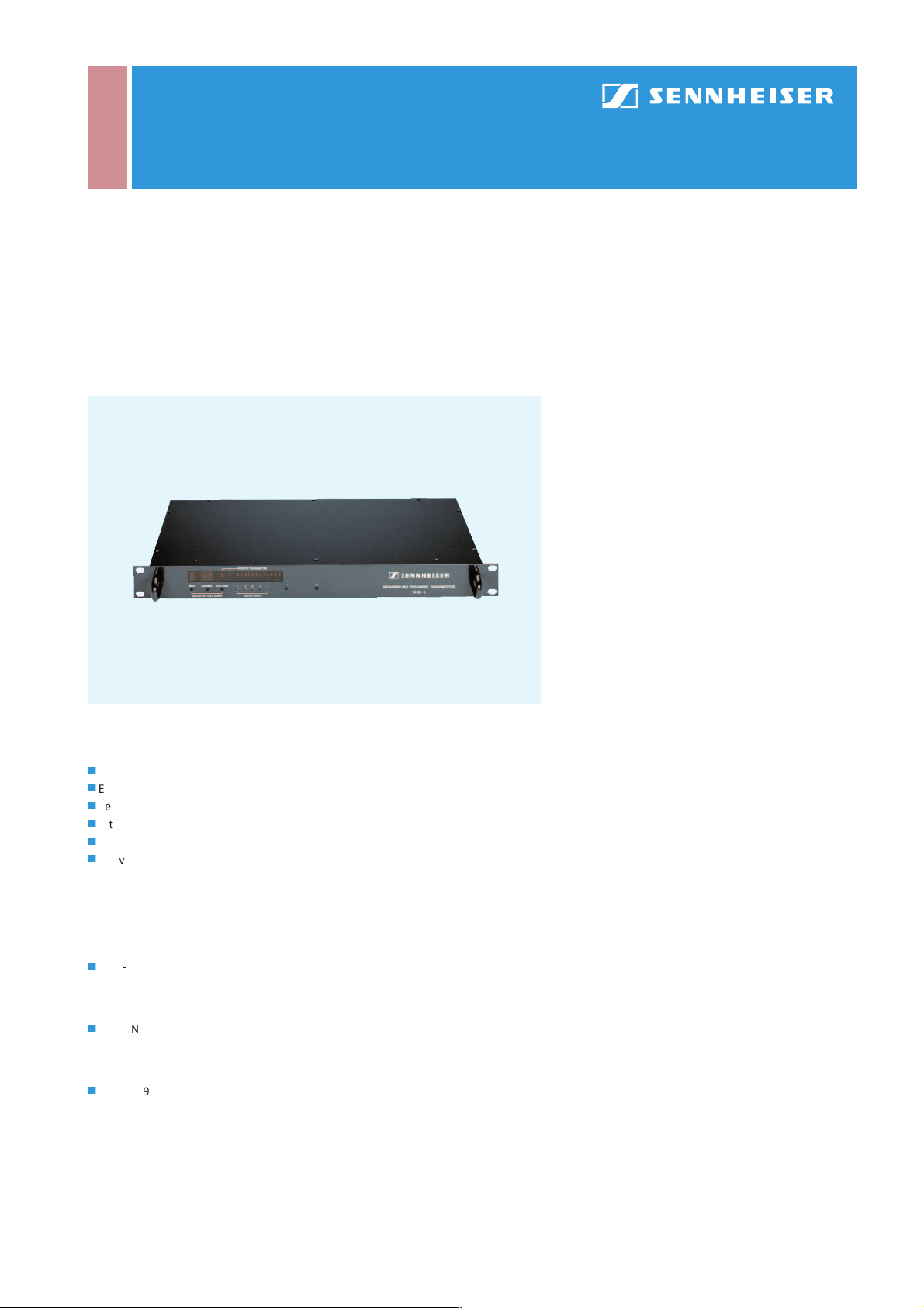
The SI 29-5 is a 5-channel modulator. Its audio channels can be programmed to any
of the 32 narrow-band channels, and monitoring is no problem due to integrated IR
transmission diodes. The modulator is easy to program and features clear LED displays for monitoring all modulator functions.
Tec hnic al Da t a
Modulation .................................................narrow-band FM
Nominal/peak deviation...........................± 6 kHz/± 7 kHz
Amplitude limitation..... limiting amplifier (max. 30 dB)
Deviation display .................peak/5 dB/3 dB/ 1 dB/0 dB/
–1 dB/–3 dB/–5 dB/–7 dB/
–10 dB/–15 dB/–20 dB
Audio channels ..................................................................five
Channel frequencies .................................... 55 – 1,335 kHz
AF inputs I .........................................transformer-balanced
XLR-3F sockets, optional
12 V phantom powering
AF input II..................................... 25-pole sub-D socket, in
parallel with AF inputs I,
optional 12 V phantom powering
Input sensitivity................... 50 mV – 1.5 V (line) optional
0.5 mV – 30 mV (microphone)
AF frequency response................................50 – 12,000 Hz
THD ................................................................................< 0.5 %
AF signal-to-noise ratio................................. > 70 dB (A)
RF outputs................................ 2 x BNC, short-circuit-proof
RF cascading sockets .................................................2 x BNC
Output impedance...........................................................50 Ω
Features
j
Modulator with up to five narrow-band audio channels
j
Each audio channel can be programmed to any of the 32 carrier frequencies
j
Several units can be cascaded to make systems of up to 32 channels
j
Integrated IR monitoring diodes
j
19“ (1 U) housing
j
Delivery includes: 1 x SI 29-5 modulator
Suppression of harmonics........................................ > 60 dB
Power supply ......... 12 V AC, via NT 29 plug-in mains unit
Power consumption .............................................max. 17 W
Dimensions .............................approx. 485 x 45 x 340 mm
Weight .................................................................approx. 4 kg
Cat. No. 003986
rms
Recommended Accessories
j
Plug-in mains unit
NT 29 European version Cat. No. 004002
NT 29-120 USA version Cat. No. 004003
NT 29-UK UK version Cat. No. 004004
j
BNC-BNC co-axial cable
GZA 1019 A 1 (1 m) Cat. No. 002324
GZA 1019 A 5 (5 m) Cat. No. 002325
GZA 1019 A 10 (10 m) Cat. No. 002326
j
GZV 1019 A BNC coupler Cat. No. 002368
SI 29-5
IR Audio Transmission Technology | Modulators/Radiators
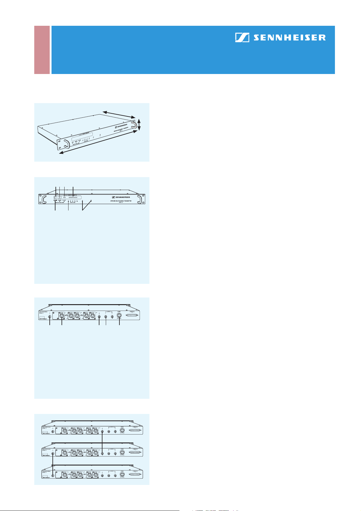
The SI 29-5 is a multi-channel modulator in a compact 19“ (1U) housing. Five audio
340 mm
485 mm
Dimensions of the SI 29-5
1 2 3 4
5 6 7
1 LED display for indicating the audio channel (1 – 5)
2 LED display for indicating the transmission
channel (0 – 31)
3 IR transmitting diodes for monitoring the RF
output signal
4 LED bargraph for deviation display
5 Menu keys
6 five LEDs for indicating the audio inputs which
deliver their signal to the RF output
7 +/– keys
SI 29-5 front panel
1 2 3 4 56
1 BNC RF cascading socket for connecting
additional SI 29-5
2 Five XLR-3F audio inputs, transformer balanced
3 BNC RF cascading socket for connecting
additional SI 29-5
4 BNC RF outputs to radiators, short-circuit-proof
5 Socket for plug-in mains unit, connector is twist-
locked to the socket
6 25-pole sub-D socket for all audio inputs,
in parallel with the XLR-3 inputs
channels can be programmed to any of the 32 standardised narrow-band channels.
Using the cascading sockets at the back, up to seven SI 29-5 can be cascaded to
make a 32-channel system. The AF inputs at the back of the modulator are available twice. You have a choice of either feeding the audio signals to separate XLR-3F
45 mm
sockets or to a 25-pole central sub-D connector for all inputs. Both input types are
connected in parallel and balanced by a transformer.
The modulator is programmed with the menu keys and the +/– buttons. By simultaneously pressing the INPUT key and either the + or – key, you can select the audio
channel to be transmitted. With CHANNEL, you can assign one of the 32 standardised carrier frequencies to the selected audio channel. To avoid accidental reprogramming, you need to hold the CHANNEL key for about 1.5 seconds af ter you have
released the +/– but tons i n order to make the modulator accept the new carrier
frequency. Beside channels 0 – 31 you can also choose the “OF” (off) position, which
switches the audio channel off. The corresponding LED will go out. Switching of f
unused channels will increase your radiators’ output power as the number of channels reduces the radiator coverage area accordingly.
The AF LEVEL key serves to adjust the sensitivity of the corresponding audio input.
You can adjust line signals between 50 mV and 3 V in 50 steps. All modulator settings are stored in an EEPROM. As a result, the data remain stored even if the modulator has been disconnected from the mains for a long period of time. With the help
of the two IR monitoring diodes, you can listen to the RF signal with a suitable IR
receiver – even when the radiators have not yet been connected or do not cover the
technicians’ area.
You can connect two chains of IR radiators to the RF outputs of the SI 29-5. The BNC
sockets are short- circuit-proof. By means of the RF cascading sockets, the summing
signals of several SI 29-5 can be mixed. The two sockets are connected in parallel
and can be used both as an input and as an output.
For example, to set up a 15-channel system as shown in the drawing at the bottom
left, simply connect the modulators (no particular order necessary) with BNC-BNC
cables. The signal of all modulators will be available at any of the RF output sockets,
and you can operate the devices just as before. When setting up multi-channel
systems, you have to pay special attention not to assign a carrier frequency twice.
Even if one channel only transmits the carrier, the transmission of the modulated
signal on the other channel will be disturbed.
SI 29-5 back panel
 Loading...