

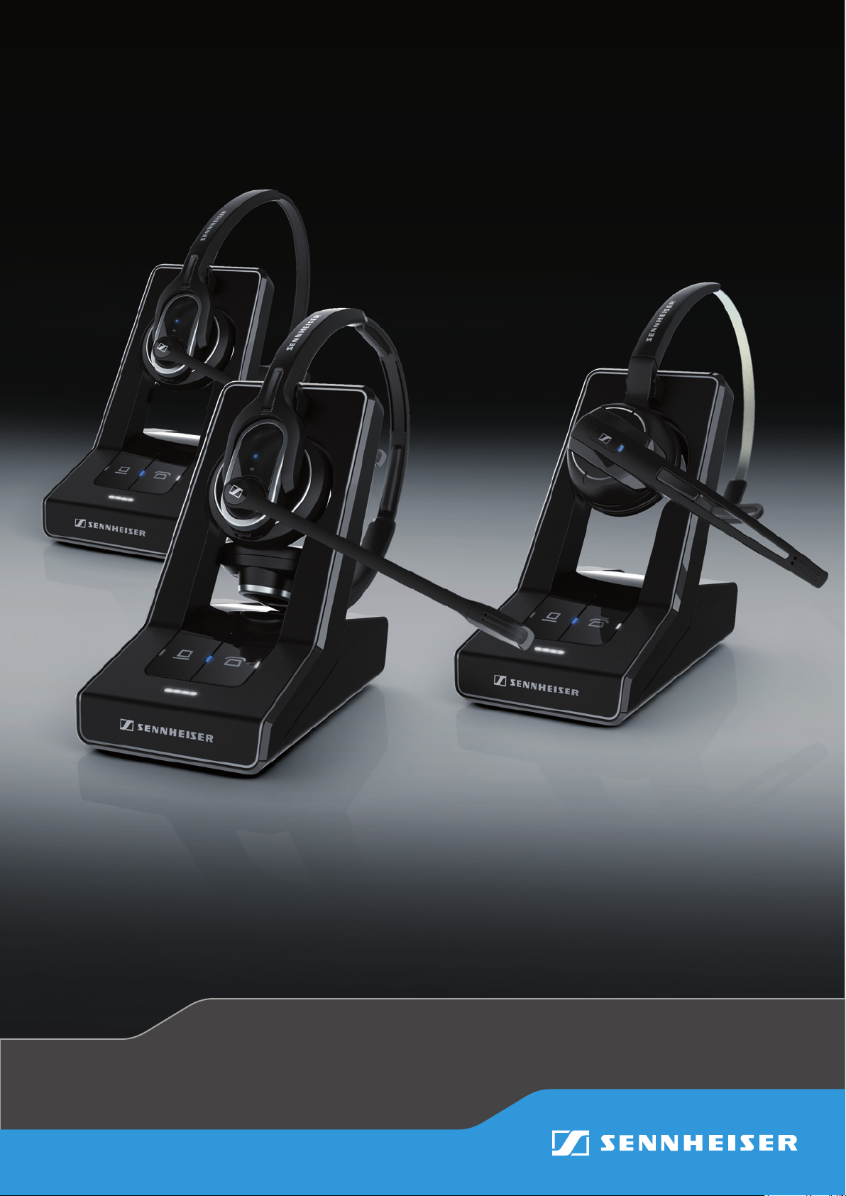
Sennheiser SD Pro1 HS, SD Pro2 HS binaural, SD Office HS, SD Office HS monaural, SD Pro2 HS User Manual
...Page 1
DECT
Comfort
call
UserGuide
SD Series
Instruction Manual
Page 2

Contents “User Guide”
Contents “User Guide”
Important safety information ....................................................................... 2
Scope of delivery and overview of the SD series ........................................ 4
Base stations with components ................................................................... 4
Headsets with components .......................................................................... 5
Product overview of the headsets ................................................................ 6
Overview of the SD Office – HS headset ....................................................6
Overview of the SD Pro1/Pro2 – HS headsets .......................................... 7
Overview of the buttons ............................................................................... 8
Overview of the LEDs ..................................................................................... 9
Individually adjusting the headset ............................................................11
Putting the headset on and adjusting it ..................................................11
Labeling the headset with a name plate .................................................14
Testing the headset system and the sound quality ................................ 15
Adjusting the headset system using the DIP switches .........................15
Pairing the headset and the base station ...............................................17
Adjusting the audio signal by means of the dial tone ..........................18
Adjusting the volume ..................................................................................19
Adjusting the automatic audio transmission “Auto Audio” ................19
Making calls using the headset ..................................................................20
Adjusting the volume ..................................................................................20
Muting the headset’s microphone ............................................................21
If you leave the DECT range ........................................................................22
Switching between Phone and PC mode ..................................................22
Calling via the fixed line phone using the headset ................................23
Calling via the computer using the headset ............................................25
Holding a conference call ............................................................................27
Charging the headset and storing the headset system .......................... 29
Charging the headset ...................................................................................29
Switching the headset system off during extended non-use .............31
Sharing a workplace .....................................................................................32
Cleaning and maintaining the headset system ........................................ 34
Replacing the ear pads ................................................................................35
Replacing the headset’s rechargeable battery .......................................36
If a problem occurs ....................................................................................... 39
Specifications ................................................................................................40
Manufacturer Declarations ..........................................................................42
SD Series - User Guide | 1
Page 3

Important safety information
Important safety information
왘 Please read this instruction manual carefully and completely before
using the product.
왘 Always include this instruction manual when passing the product on to
rd parties.
thi
왘 Do not use an obviously defective
product.
Preventing damage to he
왘 Do not listen at high volume levels for long periods of time to prevent
ing damage.
hear
왘 Always maintain a distance of at le
cups and the cardiac pacemaker or implanted defibrillator since the
product generates permanent magnetic fields.
왘 Keep the product, accessories and pac
dren and pets to prevent accidents and choking hazards.
왘 Do not use the product in situations which require special attention.
Preventing damage to the product and malfunctions
왘 Always keep the product dry and do not
tures (hairdryer, heater, extended exposure to sunlight, etc.) to avoid
corrosion or deformation.
왘 Only use attachments/accessories sup
heiser.
왘 Only clean the product with a soft, dry cloth.
왘 Unplug the power supply unit from the wa
connect the product from the mains power supply.
왘 Do not short-circuit the contacts of t
metal objects (e.g. paper clips, hair pins, earrings) come into contact
with the interfaces and contacts.
왘 Only use the base station for charging SD series headsets.
alth and accidents
ast 3.94” (10 cm) between the ear
kaging parts out of reach of chil-
expose it to extreme tempera-
plied or recommended by Senn-
ll socket to completely dis-
he product. Make sure that no
Intended use/Liability
The headset system can be used for cal
(VoIP) and/or a telephone – for audio input/output and is intended for
professional office or call center use.
It is considered improper use when this product is used for any application
not named in this instruction manual.
Sennheiser does not accept liability for damage arising from abuse or
misuse of this product and its attachments/accessories. The risk is to be
borne by the user.
Sennheiser is not liable for damages to USB devices that are not consistent
with the USB specifications.
Sennheiser is not liable for damages resulting from the loss of connection
due to flat or overaged rechargeable batteries or exceeding the DECT
transmission range.
The US base stations operate on special transmission frequencies whose
use is not authorized outside the United States.
왘 Do not use the SD BS US base station outside the United States.
ling and – together with a computer
2 | SD Series - User Guide
Page 4
Important safety information
Safety instructions for Lithium-P
In extreme cases, abuse or
WARNING
•explosion,
•
fire development,
• heat generation or
•smoke/gas development.
Switch rechargeable
battery-powered
products off after use.
Only charge
rechargeable
batteries at ambient
temperatures
between 10°C/50°F
and 40°C/104°F.
Dispose of defective
products with built-in
rechargeable batteries
at special collection
points or return them to
your specialist dealer.
misuse of rechargeable batteries can lead to:
olymer rechargeable batteries
Do not heat above 70°C/158°F,
e.g. do not expose to sunlight
or throw into a fire.
When not using rechargeable
batteries for extended periods
of time, charge them regularly
(about every 3 months).
Only use rechargeable batteries
recommended by Sennheiser
and the appropriate chargers.
SD Series - User Guide | 3
Page 5
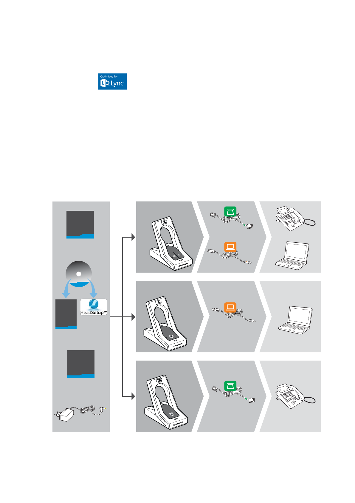
Scope of delivery and overview of the SD series
Safety
Guide
Quick
Guide
Manual
EU/UK/US/AU
Phone
USB
SD BS USB
SD BS USB ML
SD BS Phone
SD BS
SD BS ML
Phone
USB
Scope of delivery and overview of the
SD series
The SD series allows you to combine base stations (BS) and headsets (HS)
to meet your needs. The listed headsets and base stations are compatible
with each other. The SD series base stations marked with ML in their name
optimized for Microsoft
are
The scope of delivery includes – depending on the product purchased – a
base station and/or a headset with corresponding components.
Base stations with components
SD BS for fixed line phone and computer
SD BS ML for fixed line phone and computer, optimized for
SD BS USB for computer
SD BS USB ML for computer, optimized for Microsoft Lync
SD BS Phone for fixed line phone
Microsof
Lync™.
t Lync
4 | SD Series - User Guide
Page 6
Scope of delivery and overview of the SD series
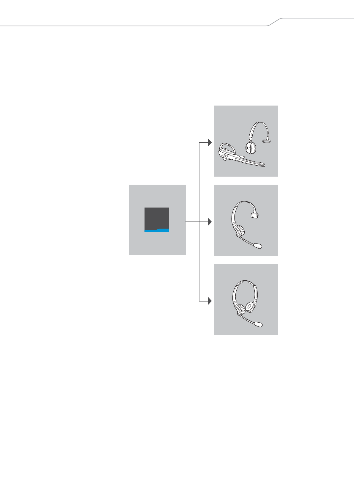
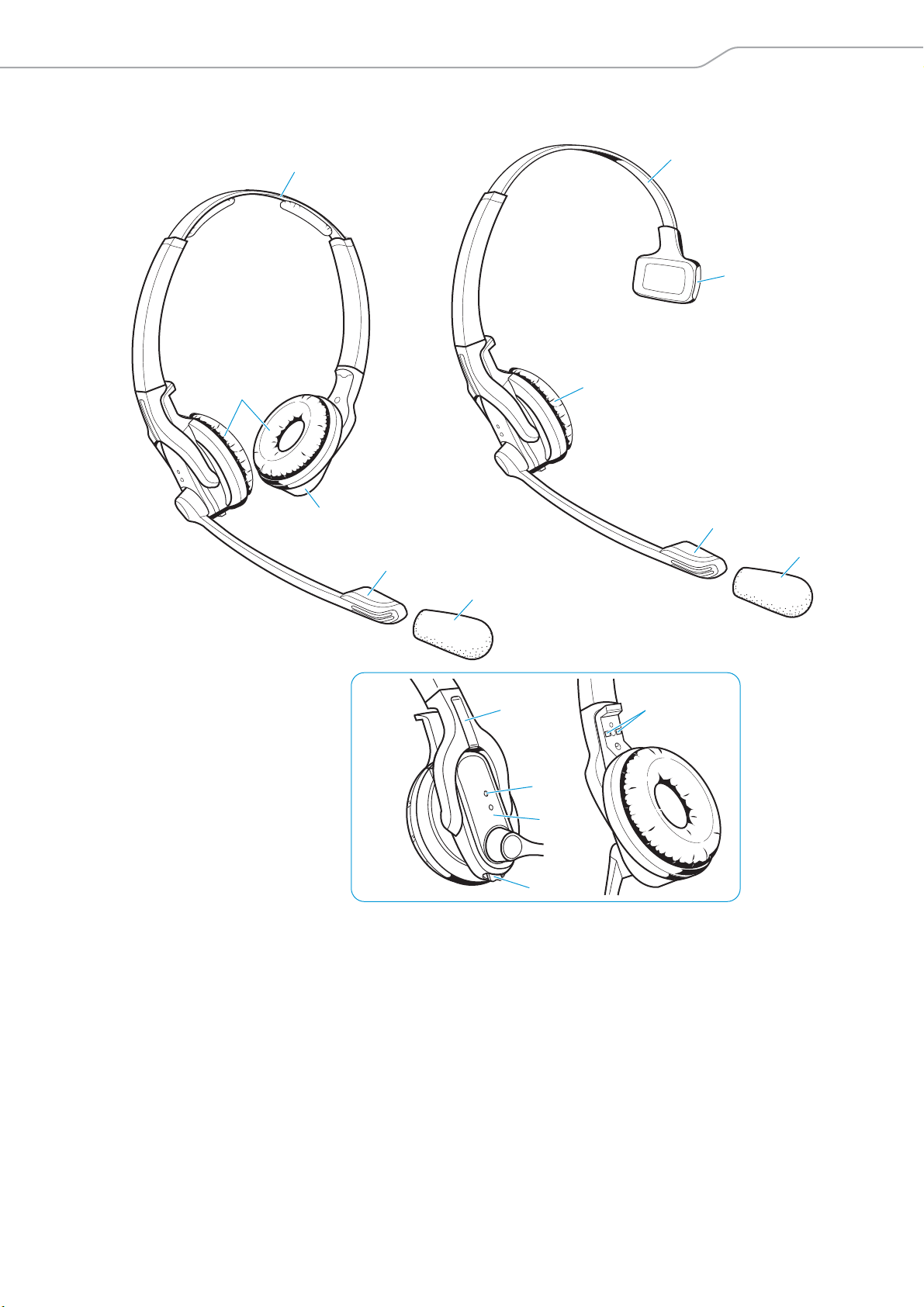
Headsets with components
SD Office – HS monaural, with different wearing styles
SD Pro1 – HS monaural, with headband
SD Pro2 – HS binaural, with headband
SD Office – HS
Quick
Guide
SD Pro1 – HS
SD Pro2 – HS
SD Series - User Guide | 5
Page 7
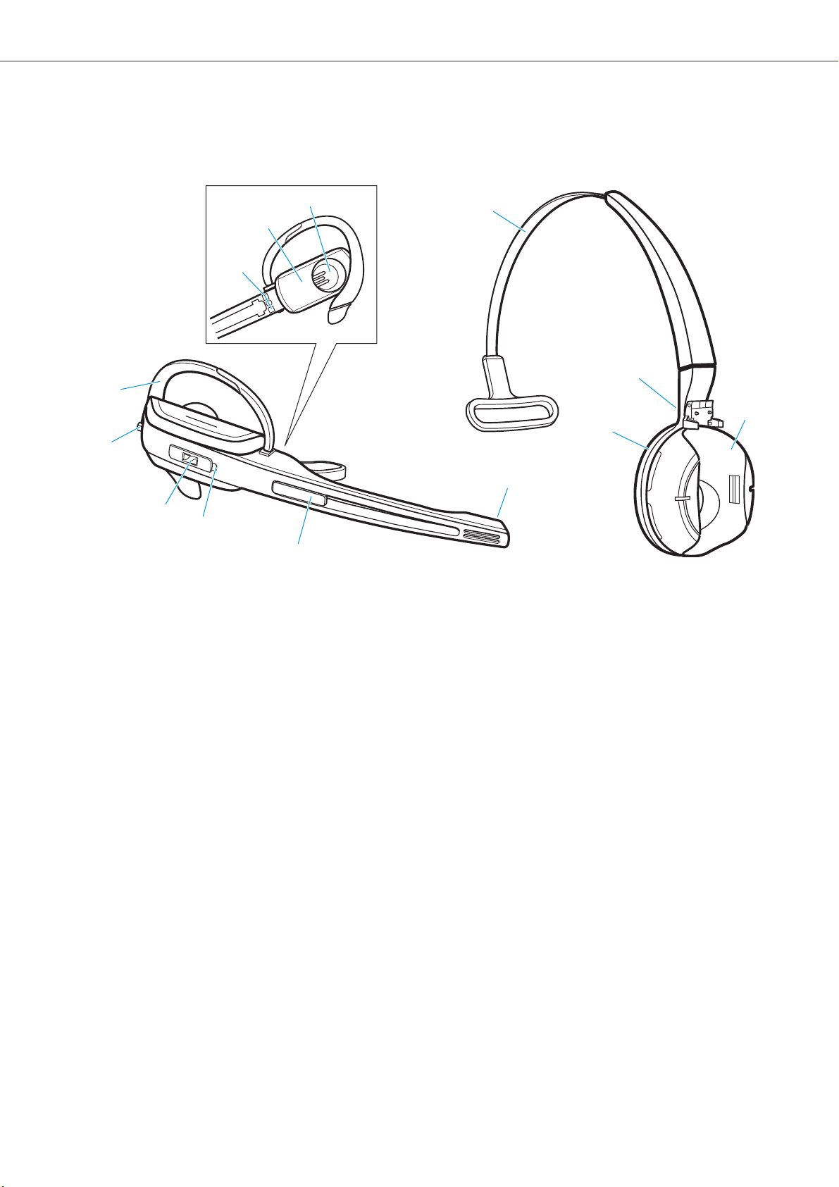
Product overview of the headsets
Product overview of the headsets
Overview of the SD Office – HS headset
9
0
8
7
A
B
C
6
1 Headband
2 Charging contacts
1
2
3
4
5
8 Link button
9 Audio button
3 Headset holder
4 Ear pad
5 Microphone
6 Name plate
7 Headset LED
0 Ear hook
A Charging contacts
B Battery compartment
C Ear piece
6 | SD Series - User Guide
Page 8
Product overview of the headsets
SD Pro1 – HS
4
5
9
8
7
6
0
SD Pro2 – HS
2
4
3
3
5
1
2
1
Overview of the SD Pro1/Pro2 – HS headsets
1 Windshield
2 Microphone
3 Battery compartment
4 Ear pad
6 Name plate
7 Headset LED
8 Link button
9 Audio button
5 Headband
0 Charging contacts
SD Series - User Guide | 7
Page 9
Product overview of the headsets
Overview of the buttons
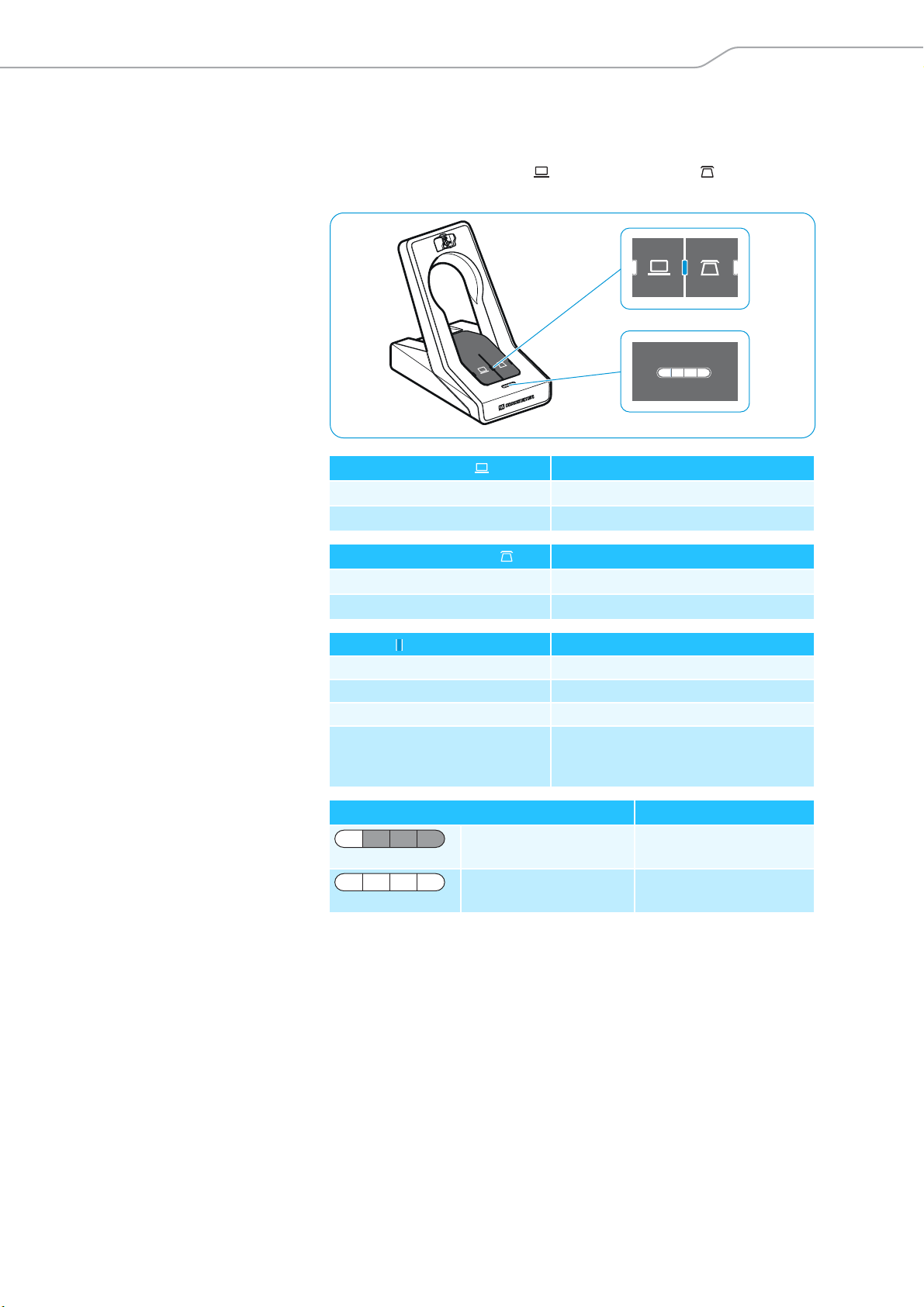
Overview of the buttons of the base station
SD BS
SD BS ML
Action Functions Page
왘 Press the Phone button Selects the Phone mode 23
왘 Press the PC button Selects the PC mode 25
Overview of the buttons of the headset
SD Office – Headset SD Pro1/Pro2 – Headset
SD BS USB
SD BS USB ML
Establishes/disconnects the link
between headset and base station
Accepts/ends a call 23
Establishes/disconnects the link
between headset and base station
Accepts/ends a call 25
SD BS Phone
17
17
8 | SD Series - User Guide
Action Functions Page
왘 Press the
Link button 8
왘 Press and hold the
Link button 8 for
econds
5s
왘 Push the
Audio button 9
pwards/downwards
u
왘 Press the
Audio button 9
왘 Press and hold the
Link button 8 and
he Audio button 9
t
seconds
for 5
Establishes/disconnects the link
between headset and base station
Accepts/ends a call 23/25
Switches the headset on/off 31
Adjusts the ring tone volume, the
volume of the acoustic signals or the
audio volume
Mutes the microphone/unmutes the
microphone
Changes the direction of the volume
up/down function of the Audio
button
Special pairing mode 33
17
20
21
21
Page 10
Product overview of the headsets
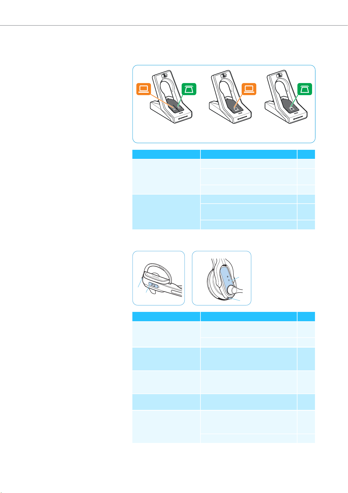
Overview of the LEDs
Overview of the LEDs of the base station
The LED icons of the PC button and
on the base station variant.
LED of the PC button Meaning
lights up PC mode
flashes Incoming PC call
the Phone button are dependent
LED of the Phone button Meaning
lights up Phone mode
flashes Incoming telephone call
Link LED Meaning
lights up blue Active link to the headset
lights up red No link to the headset
flashes red Headset is muted
is off Standby mode, headset is within the
range of the base station, but no audio
link
Charge status LED (white = lit) Meaning
LED segment 1 flashes Rechargeable battery
is almost flat
LED segments 1 – 4
are lit
Rechargeable battery
is charged
SD Series - User Guide | 9
Page 11
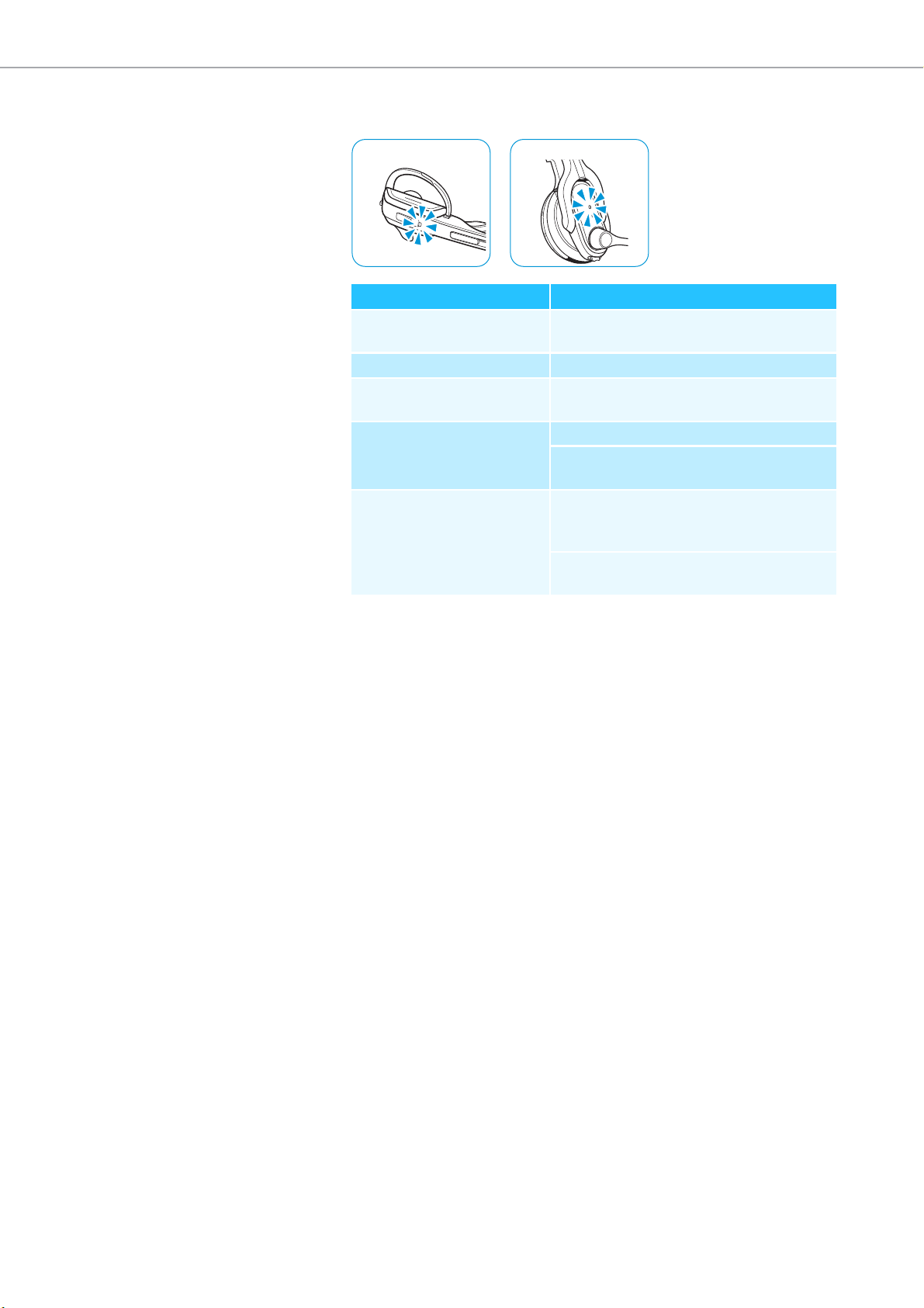
Product overview of the headsets
SD Office – HS SD Pro1/Pro2 – HS
O
verview of the LEDs of the headset
Headset LED Meaning
lights up blue Headset is being charged in the base
station
flashes blue slowly Active link to base station
flashes 3 times red
Rechargeable battery is almost flat
repeatedly
is off Standby mode or headset is switched off
Headset’s rechargeable battery is fully
charged
flashes blue/red Special pairing mode/direction of the
volume up/down function of the
Audio button is being changed
Pairing of an additional headset with the
base station/conference call
10 | SD Series - User Guide
Page 12
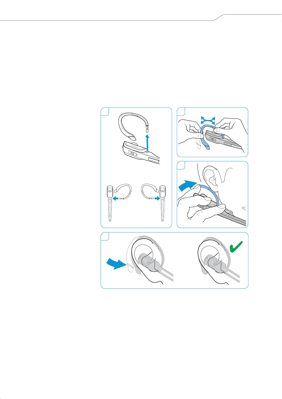
Individually adjusting the headset
1 2
3
4
Left
Right
Individually adjusting the headset
Putting the headset on and adjusting it
Using the SD Office – HS with the ear hook
1 Insert the ear hook into the ear hook slot.
2 Pre-shape the ear hook by bending it slightly.
3 Place the ear hook around your ear.
4 Bend the flexible ear hook so that the headset sits comfortably and
y on your ear.
securel
SD Series - User Guide | 11
Page 13
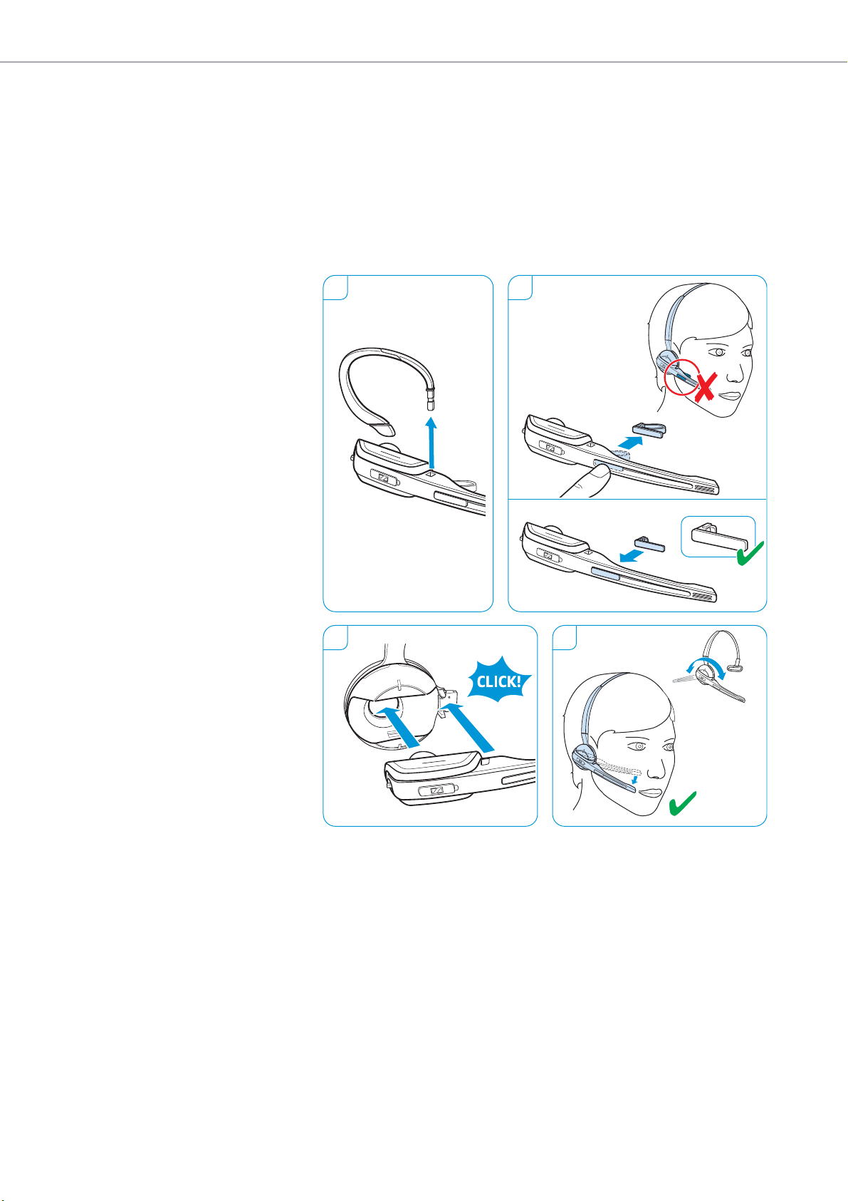
Individually adjusting the headset
1 2
3 4
Left
Right
U
sing the SD Office – HS with the headband
1 Remove the ear hook by carefully pulling it upwards.
2 Replace the name plate with cheek spac
er with the basic name plate.
This is necessary in order to be able to rotate the headset’s microphone
boom (see diagram 4).
3 Attach the headset to the headset holder of the headband.
4 Rotate the microphone boom and adjust the headset so that the ear
sts comfortably on your right or left ear.
pad re
12 | SD Series - User Guide
Page 14
Individually adjusting the headset
SD Pro1 – HS SD Pro2 – HS
2-3 cm
RightLeft
1 2
3 4
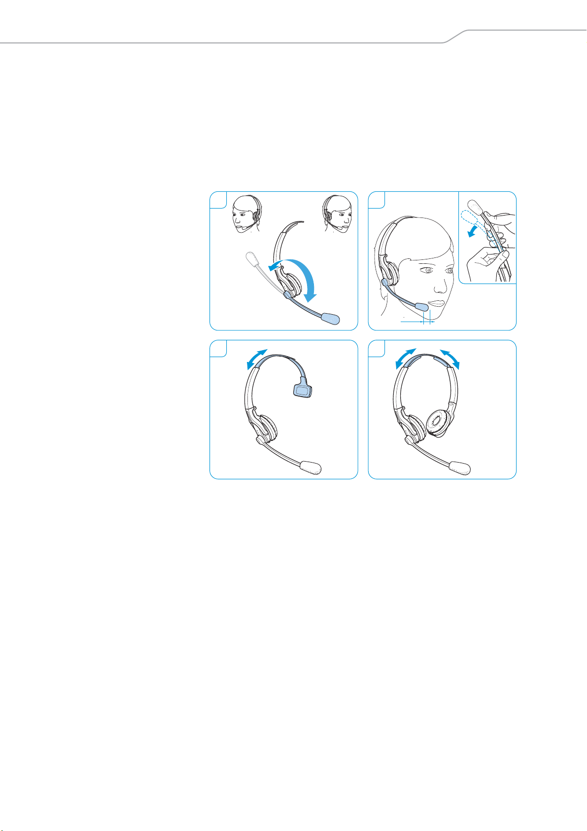
Using the SD Pro1/Pro2 – HS
1 Rotate the microphone boom.
2 Bend the microphone boom so that the microphone is about 0.8”
cm) from the corner of your mouth.
(2
3SD Pro1 – HS: Adjust the headset so that the ear pad rests comfortably
your right or left ear.
on
4SD Pro2 – HS: Adjust the headset so that the ear pads rest comfortably
your ears.
on
SD Series - User Guide | 13
Page 15

Individually adjusting the headset
Labeling the headset with a name plate
왘 Change the lettering of the name plate.
1. OPEN ”Name Plate Maker“
2. TYPE
3. PRINT
4. CUT
WWW
Instruction Manual
www.sennheiser.com/
name-plate-maker
DW Office – HS
DW Pro1 – HS
DW Pro2 – HS
14 | SD Series - User Guide
Page 16

Testing the headset system and the sound quality
Testing the headset system and the
sound quality
Adjusting the headset system using the DIP switches
1 Press the Link button on the headset to disconnect an existing wireless
link between base station and headset.
The LEDs on the headset and on the base
2 Use a pointed object (e.g. a ball pen) to set the DIP switches to the
red position.
desi
station go off.
1
2
Configuring the handset lifter/hook switch –
Extra
Settings
Handset Lifter
Auto Link OFF
Long Range
Wideband
1 2 3 4 5 6
DHSG
Fast Link
MSH
Short Range
Narrowband
Auto Link ON
Limiter
DIP switches 1 and 2
Standard
The DIP switches 1 and 2 are only assigned a
SD BS ML and SD BS Phone base stations.
Switch position Function
Manual operation
Lifts/hangs up the handset manually or using
the handset lifter (Sennheiser HSL 10).
Electronic hook switch (DHSG standard)
Call control via the headset system.
For faster link establishment, see Fast Link.
Electronic hook switch (MSH standard)
Call control via the headset system.
Fast Link for DHSG standard and HSL 10 handset
lifter
Recommended for frequent callers. Shorter battery
life. Fast link establishment without delay due to
hidden link to the base station.
SD Series - User Guide | 15
function on the SD BS,
Page 17

Testing the headset system and the sound quality
A
djusting the radio range – DIP switch 3
If many DECT systems are operated in a
occur. In this case, you should change the radio range.
Switch position Function
Automatically establishing the wireless link between headset and
base
station (Auto Link) – DIP switch 4
Switch position Function
Auto Link
SD Office – HS
SD Pro1 – HS
SD Pro2 – HS
confined space, interference can
Standard radio range
Reduced radio range
Use this setting in order to avoid interference with
other DECT systems
Range of approx. 10 m indoors
Manual link establishment
When taking the headset out of the base station,
you have to manually establish the wireless link
between headset and base station.
Automatic link establishment – Auto Link
When taking the headset out of the base station,
a wireless link is automatically established between
headset and base station.
Switching between wideband and narrowband audio transmission –
DIP switch 5
Switch position Function
Wideband audio transmission
Automatic frequency adjustment of wideband and
narrowband calls. Wideband audio transmission is
e.g. supported by Skype and gives high speech
quality.
Battery life: 8 hours
Narrowband audio transmission
Battery life: 12 hours
Limiting the volume – DIP switch 6
Switch position Function
Standard limitation
Limited volume (country specific)
•AU version:
in compliance with Directive AS/ACIF G616:2006
• EU and US version:
in compliance with Directive 2003/10/EC
16 | SD Series - User Guide
Page 18

Testing the headset system and the sound quality
3x
Pairing the headset and the base station
Upon delivery, the headset and the base station are already paired. You
only have to pair the headset with the base station if you have purchased
the headset and base station separately or if you want to hold a conference call.
“easy pairing” – Pairing the headset and the base station
왘 Place the headset into the magnetic hol
The Headset LED alternately flashes red and blue. If pairing is successful, the Headset LED flashes 3 times blue and then lights up continuously, indicating that the base station and the headset are paired.
If the Headset LED flashes 3 times red and then goes off, start a new
pairing attempt by placing the headset again into the magnetic holder of
the base station.
Establishing a wireless link
왘 Press the Link button on the headset or press
PC or Phone ) on the base station. The link is established. The Link
LED on the base station lights up blue and the Headset LED flashes
blue slowly.
der of the base station.
the backlit button (either
Disconnecting a wireless link
왘 Press the Link button on the headset or press
PC or Phone ) on the base station. The link is disconnected. The
Link LED on the base station and the Headset LED go off. The headset
is in standby mode.
If your telephone has a built-in electronic hook switch supporting
the MSH standard, you can only disconnect the wireless link between
headset and base station by placing the headset into the base
station.
the backlit button (either
SD Series - User Guide | 17
Page 19

Testing the headset system and the sound quality
Adjusting the audio signal by means of the dial tone
1 Put on the headset and press the Phone button on the base station.
2 Press the Link button on the headset. The Link LED on the base
tation lights up blue.
s
3 Lift the handset. You hear a dial tone.
4 Set the ABC switch to the position A, B or C so that you can hear a clear
al tone in the headset.
di
1 2
43
18 | SD Series - User Guide
Page 20

Testing the headset system and the sound quality
Adjusting the volume
Adjusting the microphone volume of the call transmission
By default, the microphone volume control is set to position 4. This setting
is
suitable for most telephones.
왘 Make a call to someone who will help you find the correct sensitivity
ing for your microphone.
sett
왘 Turn the microphone volume control so that the other party can hear
u at a comfortable level.
yo
Adjusting the microphone volume of the USB transmission
Some softphones adjust the microphone sensit
왘 Activate this function in order to be able to optimally use the micro-
phone and,
tivity so that the other party can hear you at a comfortable level (see
the Help function of your operating system).
via your operating system, adjust the microphone sensi-
ivity automatically.
Adjusting the automatic audio transmission “Auto Audio”
With the “Auto Audio” function activated and in the case of a USB connection, the audio signals – e.g. from Windows
are automatically transmitted to the headset.
When you receive a call or when a connection to Skype™ is established, the
audio transmission stops and you hear for example the ring tone. The
“Auto Audio” function is activated by default.
Activating the “Auto Audio” function
왘 Use a pointed object to press the Set button for approx. 5 seconds. The
nk LED rapidly flashes blue several times.
Li
Deactivating the “Auto Audio” function:
왘 Use a pointed object to press the Set button for approx. 5 seconds. The
nk LED rapidly flashes red several times.
Li
Media Player or iTunes –
5s
SD Series - User Guide | 19
Page 21

Making calls using the headset
SD Pro1 – HS
SD Pro2 – HS
SD Office – HS
Making calls using the headset
Adjusting the volume
WARNING
Hearing damage due to high volumes!
Listening at high volume levels for long periods can lead to permanent hearing defects.
왘 Set the volume to a low level b
왘 Do not continuously expose yourself to high volumes.
You can adjust the ring tone volume, the volume of the acoustic signals
and of the audio signal using the Audio button. With base stations connected to a computer, you can also adjust the volume of the audio signal
by using the volume control of your operating system.
Adjusting the ring tone volume and the volume of the acoustic signals
왘 Make sure that the headset is in standby mode (the Link LED on the
base station is off).
왘 To adjust the volume, move the Audio button as shown in the diagram.
en the minimum or maximum volume is reached, you hear a double
Wh
beep in the headset.
If necessary, press the Link button on the headset.
efore putting on the headset.
Adjusting the volume of the audio signal
You can adjust the volume of the audio signal by means of the dial tone or
ing a call.
dur
왘 Make sure that a link is established between headset and base station
the Link LED on the base station lights up blue). If necessary, press
(
the Link button on the headset.
왘 To adjust the volume, move the Audio button as shown in the diagram.
en the minimum or maximum volume is reached, you hear a double
Wh
beep in the headset.
SD Office – HS
SD Pro1 – HS
SD Pro2 – HS
20 | SD Series - User Guide
Page 22

Making calls using the headset
Changing the direction of the volume up/down function
왘 On the Audio button, check which direction is assigned “volume down”.
왘 Simultaneously press and hold the Li
nk button and the Audio button
for 5 seconds.
The Headset LED alternately flashes blue/red.
SD Office – HS
5 s
SD Pro1 – HS
SD Pro2 – HS
5 s
왘 Push the Audio button in the direction “volume down” until the
H
eadset LED goes off. The direction of the volume up/down function of
the Audio button is changed. The headset switches to standby mode.
SD Office – HS
SD Pro1 – HS
SD Pro2 – HS
Muting the headset’s microphone
왘 Press the Audio button.
The microphone is muted. While the microphone is muted, the
Link LED on the base station flashes red.
SD Office – HS
Unmuting the headset’s microphone
왘 Press the Audio button.
ou hear a beep in the headset. The muting is canceled and the
Y
Link LED on the base station lights up blue.
SD Pro1 – HS
SD Pro2 – HS
SD Series - User Guide | 21
Page 23

Making calls using the headset
55 m
If you leave the DECT range
In normal office buildings, the range between headset and base station is
up to 55 m. If, during a call, the audio quality deteriorates or the link breaks
down completely, you hear a descending sequence of beeps in the headset.
The Link LED on the base station lights up red.
왘 Re-enter the DECT range of the base station within 60 seconds.
hear a ring tone in the headset.
You
왘 Press the Link button on the headset to resume the call.
softphone supports call control, the call will automatically be
If your
ended 60 seconds after leaving the DECT range.
Switching between Phone and PC mode
왘 Press the PC button or the Phone button on the base station to
select the desired mode.
The button pressed (PC or Phone ) is backlit in white, indicating the
selected mode.
22 | SD Series - User Guide
Page 24

Making calls using the headset
Calling via the fixed line phone using the headset
If you want to use the headset to accept, make or end calls, you have to
establish a wireless link between headset and base station. You can choose
between manual and automatic link establishment (see “Auto Link” on
page 16):
Switch position Function
Manual link establishment
When taking the headset out of the base station,
you have to manually establish the wireless link
between headset and base station.
Automatic link establishment – Auto Link
When taking the headset out of the base station,
a wireless link is automatically established between
headset and base station.
Managing calls without using a call control functi
Accepting a call:
왘 Press the Link button on the headset.
왘 Lift the handset or press the “accept call” button on your fixed line
ne.
pho
Making a call:
왘 Press the Link button on the headset to esta
station and headset.
왘 Lift the handset and dial the desired number.
hone connection is established.
The p
You hear the ring tone of the fixed line phone.
onality
blish a link between base
Ending a call:
왘 Hang up the handset or press the “end call” button on your fixed line
ne.
pho
SD Series - User Guide | 23
Page 25

Making calls using the headset
Managing calls using a call control
Accepting a call:
왘 Press the Link button on the headset to accept the call.
The handse
Making a call:
왘 Dial the desired number.
왘 Press the Link button on the headset to establish a link between base
tation and headset.
s
The phone connection is established automatically.
Ending a call:
왘 Press the Link button. If the other
your headset become automatically ready to receive the next call.
You hear a ring tone in the headset.
t lifter/electronic hook switch lifts the handset.
functionality (EHS, HSL 10)
party hangs up, your telephone and
Frequent callers who use an electronic hook switch with DHSG capability
are recommended to activate the “Fast Link” function for faster link establishment (see page 15):
Switch position Function
Fast Link (only when DHSG standard is used)
Recommended for frequent callers. Shorter battery
life. Fast link establishment without delay due to
hidden link to the base station.
Switching a call between head
왘 Press the Link button on the headset
handset of the fixed line phone during an ongoing call.
In case of a fixed line phone with a handset lifter/an electronic hook
switch, this switching can only be done on the fixed line phone.
set and fixed line phone
to switch between headset and
24 | SD Series - User Guide
Page 26

Making calls using the headset
Calling via the computer using the headset
If you want to use the headset to accept, make or end calls, you have to
establish a wireless link between headset and base station. You can choose
between manual and automatic link establishment (see “Auto Link” on
page 16):
Switch position Function
Manual link establishment
When taking the headset out of the base station,
you have to manually establish the wireless link
between headset and base station.
Automatic link establishment – Auto Link
When taking the headset out of the base station,
a wireless link is automatically established between
headset and base station.
Managing calls without using the “HeadSetup” call control functionality
Accepting a call:
hear a ring tone in the headset.
왘 Click on “Accept call” on your softphone.
king a call:
Ma
왘 Press the Link button on the headset to esta
station and headset. If the “Auto Audio” function is activated, this step
is not necessary (see page 19).
왘 Start the call using your softphone.
ding a call:
En
왘 End the call using your softphone.
The softphone signals that you are receiving a call. You
blish a link between base
SD Series - User Guide | 25
Page 27

Making calls using the headset
Managing calls using the
Accepting a call:
hear a ring tone in the headset.
왘 Press the Link button on the headset to accept the call.
aking a call:
M
왘 Start the call using your softphone, the audio s
transmitted to the headset.
Ending a call:
The softphone signals that you are receiving a call. You
“HeadSetup” call control functionality
ignal is automatically
왘 Press the Link button. If the other par
your headset become automatically ready to receive the next call.
ty hangs up, your softphone and
26 | SD Series - User Guide
Page 28

Making calls using the headset
MASTER
GUEST 1
GUEST 3
GUEST 2
MASTER
New
3x
or
SD Office – HS SD Pro1 – HS
SD Pro2 – HS
Holding a conference call
The headset system allows you to make a conference call with up to
4 SD series headsets. The first headset paired (master) is used control
the call establishment and end of conversation.
Pairing the MASTER headset with the base station
The Link LED on the base station is
lights up red (no headset paired).
왘 Place the master headset into the base station.
The Headset
LED alternately flashes blue/red until a link to the base
station is established. The Headset LED flashes blue 3 times.
왘 Take the headset out of the base station and press the Link button to
onnect the headset with the base station.
c
The Link LED on the base station lights up blue.
off (headset is disconnected) or
SD Series - User Guide | 27
Page 29

Making calls using the headset
Press & hold the mute button
& insert the headset
into the charging
cradle.
MASTER
SD Pro1 – HS
SD Pro2 – HS
SD Office – HS
GUEST 1-3
or
Accept the
GUEST headset.
3x
3x on
A
dding a GUEST headset to a conference call
왘 Press and hold the Audio button while
placing the guest headset into
the base station of the master headset.
The Headset LED alternately flashes blue/red until a link to the base
station is established. The Headset LED flashes blue 3 times.
왘 Take the guest headset out of the base st
ation. You hear a beep in the
master headset.
왘 To add the guest headset to the confe
rence call, press the Link button
on the master headset within 15 seconds.
왘 Repeat this procedure to add additional guest headsets to the
confere
nce call.
28 | SD Series - User Guide
왘 Call the other party.
The Link
Dropping a GUEST headset from th
왘 Press the Link button on the guest headset.
LED on the base station flashes blue.
e conference call
The guest headset is
dropped from the conference call.
“easy pairing”
To subsequently use the guest headset with other base stations,
place the guest
headsets into the other base stations. The
Headset LED alternately flashes blue/red until a link is established.
Ending a conference call
왘 Place the master headset into the magnetic holder of the base station
end the conference call and to drop the guest headsets from the
to
conference call.
Page 30

Charging the headset and storing the headset system
SD Pro2 – HSSD Office – HS SD Pro1 – HS
100%75%25% 50%
Charging the headset and storing the
headset system
Charging the headset
Always store the headset in the base station to ensure that it is fully
charged when needed. The intelligent battery charging technology prevents over-charging.
왘 Place the headset into the magnetic hol
The Headset LED lights up blue and the rechargeable battery is being
charged. The Charge status LED on the base station indicates the
charge status:
LED segment
(white = lit up)
Shortly before the rechargeable battery is about to run flat, only one LED
segment lights up weakly. The Headset LED flashes red and you hear three
beeps. You have several minutes of battery reserve. When the rechargeable battery is flat, the headset switches off.
Required
charging time
approx. 10 min. approx. 2 hrs approx. 3 hrs
approx. 20 min. approx. 4 hrs approx. 6 hrs
approx. 40 min. approx. 6 hrs approx. 9 hrs
approx. 60 min. approx. 8 hrs approx. 12 hrs
der of the base station.
Corresponds to a talk time of
Wideband Narrowband
SD Series - User Guide | 29
Page 31

Charging the headset and storing the headset system
the headset is outside the range of the base station, it will switch
If
off after 30 minutes in order to conserve battery power.
C
harging the headset using the optional CH 10 headset charger
The CH 10 headset charger is an opti
Sennheiser partner. The CH 10 allows you to charge additional SD series
headsets, e.g. for sharing the same base station when working shifts.
onal accessory available from your
SD Office – HS
SD Pro1 – HS
SD Pro2 – HS
왘 Refer to the instruction manual of the CH 10 for more information.
30 | SD Series - User Guide
Page 32

Charging the headset and storing the headset system
P
C
DC IN
H
eadset
A
CC
PC
D
C
IN
H
e
ads
et
A
CC
Switching the headset system off during extended non-use
You can switch off the headset system (1) or the headset (2) when not
using the products for extended periods of time (e.g. when you are on
holiday).
Switching the headset system off
1 Disconnect the base station from the mains power s
upply. The base
station switches off immediately, the headset switches off about
30 minutes later.
2 Press and hold the Link button for 5 seconds to switch off the headset
ediately. The Headset LED flashes 3 times red, the headset is
imm
switched off completely.
The Link LED on the base station lights up red after a short time, the
Charge status LED on the base station goes off.
1
2 2
SD Office – HS
5 s
SD Pro1 – HS
SD Pro2 – HS
3x
3x
5 s
Switching the headset system on and pairing the components
왘 Plug the power supply unit into a wall socket. The base station is
switched on.
왘 Place the headset into the magnetic holder o
f the base station. The
Headset LED flashes 3 times blue and then lights up blue. The base
station and the headset are paired.
SD Series - User Guide | 31
Page 33

Sharing a workplace
SD Pro2 – HS
SD Office – HS
SD Pro1 – HS
3x
Sharing a workplace
The headsets and base stations of the SD series are compatible with each
other. If, for example, you share a workplace, you can use one base station
with different headsets. The last headset paired with the base station can
be used without more ado.
왘 Place the headset to be used into the m
station.
The Headset LED alternately flashes blue/red until the headset is successfully paired with the base station. The Headset LED flashes 3 times
blue and then goes off. You can now use the newly paired headset.
If pairing has failed, the Link LED on the base station lights up red or is
off. Repeat the procedure.
agnetic holder of the base
32 | SD Series - User Guide
Page 34

Sharing a workplace
5 s
5 s
SD Pro1 – HS
SD Pro2 – HS
SD Office – HS
Using the headset with a third party base station
(DECT-GAP telephone)
왘 Place the headset at a maximum distance of 1 m from the third party
base station.
왘 Simultaneously press and hold t
Audio button for 5 seconds.
The headset switches to a special pairing mode and the Headset LED
alternately flashes blue/red.
왘 Set the third party base station to a special pairing mode (see the
nstruction manual of the third party base station). The default code
i
for the headset is “0000”.
The head
cessful, the Headset LED goes off.
set pairs with the third party base station. If pairing is suc-
he headset’s Link button and
If pairing is not successful within 60 seconds, the headset switches back to
standby mode.
Pairing the headset again with a SD series base station
왘 Simultaneously press and hold t
Audio button for 5 seconds.
The headset switches to a special pairing mode and the Headset LED
alternately flashes blue/red.
왘 Place the headset into the magnetic holder o
Headset LED flashes 3 times blue and then lights up blue. The base
station and the headset are paired.
he headset’s Link button and
f the base station. The
SD Series - User Guide | 33
Page 35

Cleaning and maintaining the headset system
SD Office – HS SD Pro1 – HS
SD Pro2 – HS
Cleaning and maintaining the
headset system
CAUTION
Liquids can damage the electronics of the product!
Liquids entering the housing of the product can short-circuit the electronics.
왘 Keep all liquids far away from the product.
왘 Do not use any solvents or cleansing agents.
왘 Before cleaning, disconnect the base station from the mains power
supply.
왘 Only use a dry and soft cloth to clean the product.
왘 Clean the charging contacts of the ba
tacts of the headset from time to time using e.g. a cotton swab.
se station and the charging con-
34 | SD Series - User Guide
Page 36

Cleaning and maintaining the headset system
1
3
2
A
B
Replacing the ear pads
For reasons of hygiene, you should replace the ear pads from time to time.
Spare ear pads are available from your Sennheiser partner.
SD Office – HS
1 Carefully remove the old ear pad from the ear cup. Make sure that the
astening ring of the old ear pad is also removed from the ear cup.
f
2 Pull the collar B of the ear pad over the notch A of the headband.
3 Turn the ear pad counter-clockwise over the notch until the collar com-
letely surrounds the ear cup.
p
SD Pro1/Pro2 – HS
1 Carefully remove the old ear pad from the ear cup.
2 Attach the new ear pad to the ear cup by pressing firmly
pad.
1 2
SD Series - User Guide | 35
around the ear
Page 37

Cleaning and maintaining the headset system
1
Replacing the headset’s rechargeable battery
CAUTION
Damage to the product due to improper handling
The cables can be kinked or damaged if you open the battery compartment
too jerkily.
왘 Carefully open the battery compartment and loosen th
of the rechargeable battery.
Spare rechargeable batteries are available from your Sennheiser partner.
Only use spare rechargeable batteries recommended by Sennheiser.
SD Office – HS
e connector plug
1 Remove the earhook or the headband (see page 11)
battery compartment.
2 Carefully move the battery compartment cover in the direction of the
a
rrow until you overcome a slight resistance. Remove the rechargeable
battery and carefully loosen the connector plug of the rechargeable
battery.
3 Insert the connector plug of the new rechargeable battery into the con-
n socket. Observe correct orientation of the connector plug.
nectio
4 Close the battery compartment.
2 3
and open the
4
36 | SD Series - User Guide
Page 38

Cleaning and maintaining the headset system
SD Pro1 – HS
1 Open the battery compartment cover.
2 Remove the rechargeable battery and
plug of the rechargeable battery.
3 Insert the connector plug of the new rechargeable battery into the con-
nection
4 Replace the battery compartment cover.
1 2
carefully loosen the connector
socket. Observe correct orientation of the connector plug.
3 4
SD Series - User Guide | 37
Page 39

Cleaning and maintaining the headset system
SD
Pro2 – HS
1 Carefully remove the ear pad from the ear cup where the battery com-
partment is located.
2 Open the battery compartment.
1 2
3 Remove the rechargeable battery and c
plug of the rechargeable battery.
4 Insert the connector plug of the new rechargeable battery into the con-
n socket. Observe correct orientation of the connector plug.
nectio
5 Replace the battery compartment cover.
6 Reattach the ear pad to the ear cup by pressing fir
pad.
arefully loosen the connector
mly around the ear
3 4
5 6
38 | SD Series - User Guide
Page 40

If a problem occurs
If a problem occurs
For causes and solutions that are mainly related to the base station, refer to the chapter “If a problem occurs ...”
in the “Setup Guide”.
Problem Possible cause Possible solution Page
Headset is placed into the base
station but the Charge status
LED if off
Link between headset
and base station
cannot be established
Bad radio link between
headset and base station
Noise interference and
connection loss
Rechargeable battery cannot
be charged
Rechargeable battery is
quickly depleted even after
charging
Bad audio quality, the other
party sounds too low or too
loud
Sound from the fixed line
phone is distorted and
disturbed
Rechargeable battery is deep
discharged
Wrong operating mode
(Phone/PC)
Headset is not paired with the
base station, the Link LED
lights up red
Transmission range is
exceeded
Microphone rubs on the cheek
or perhaps the beard
Too many DECT systems within
the radio range
Distance between base station
and fixed line phone is so small
that interference occurs
Charging contacts of the
headset or the base station are
dirty
Rechargeable battery is
defective
Headset is not properly placed
into the magnetic holder of the
base station
Overaged rechargeable battery Replace the overaged rechargeable
Microphone sensitivity is not
correctly adjusted
Base station is not adjusted to
the fixed line phone.
Wait several minutes until the
Charge status LED lights up.
For quick-charging the headset:
Briefly press the Set button at the
bottom of the base station.
Press the PC button or the
Phone button to select the correct
operating mode.
Place the headset into the base
station.
Reduce the distance between
headset and base station.
Adjust the radio range. 16
Bend the microphone boom so
that the microphone is about
0.8 - 1.2” (2 - 3 cm) from the
corner of your mouth.
Reduce the radio range. 16
Set the base station to
narrowband transmission.
Increase the distance between
base station and fixed line phone.
Clean the charging contacts on
the headset and on the base
station.
Replace the defective
rechargeable battery with a new
one.
Check if the headset is properly
placed into the magnetic holder.
battery with a new one.
Adjust the microphone sensitivity. 19
Use the ABC switch to adjust the
base station to your fixed line
phone.
29
–
22
17
–
13
16
–
34
36
29
36
19
For more information and an FAQ list, please visit our website at www.sennheiser.com/cco.
If a problem occurs that is not listed in the above table or if the problem cannot be solved with the proposed
solutions, please contact your local Sennheiser partner for assistance.
To find a Sennheiser partner in your country, search at www.sennheiser.com/cco/support.
SD Series - User Guide | 39
Page 41

Specifications
Specifications
Base station
SD BS/SD BS ML
Dimensions 83 x 127 x 121 mm (W x H x D)
Weight
Operating temperature range +5°C to +45°C (+41°F to +113°F)
Storage temperature range –20°C to +70 °C (–4°F to +158°F)
SD BS USB/SD BS USB ML/SD BS Phone
Dimensions 83 x 127 x 121 mm (W x H x D)
Weight approx. 309 g
Operating temperature range +5°C to +45°C (+41°F to +113°F)
Storage temperature range –20°C to +70°C (–4°F to +158°F)
Headset
approx. 337 g
SD Office – HS
Dimensions 140 x 24 x 22 mm (W x H x D)
Weight with ear hook: approx. 22 g
with headband: approx. 50 g
Talk time narrowband: up to 12 hours
wideband: up to 8 hours
Charging time 50%: approx. 20 min
100%: approx. 1 hour
Range
(environment dependent)
Speaker type dynamic, neodymium magnet
Microphone type electret microphone, noise canceling
Operating temperature range +5°C to +45°C (+41°F to +113°F)
Storage temperature range –20°C to +70°C (–4°F to +158°F)
SD Pro1/Pro2 – HS (SD 10)
Dimensions 170 x 175 x 55 mm (W x H x D)
Weight Pro1: approx. 65 g
Talk time narrowband: up to 12 hours
Charging time 50%: approx. 20 min
Range
(environment dependent)
Speaker type dynamic, neodymium magnet
Microphone type electret microphone, ultra noise canceling
Operating temperature range +5°C to +45°C (+41°F to +113°F)
Storage temperature range –20°C to +70°C (–4°F to +158°F)
free line of sight: up to 180 m
in office buildings: up to 55 m
Pro2: approx. 85 g
wideband: up to 8 hours
100%: approx. 1 hour
free line of sight: up to 180 m
in office buildings: up to 55 m
40 | SD Series - User Guide
Page 42

Specifications
Power supply unit
Nominal input voltage 100 – 240 V~
Nominal input current max. 0.2 A
Mains frequency 50 – 60 Hz
Nominal output voltage 5.9 V
Nominal output current max. 850 mA
Operating temperature range +5°C to +45°C (+41°F to +113°F)
Storage temperature range –20°C to +70°C (–4°F to +158°F)
Relative humidity operation: 20 to 85%
storage: 20 to 95%
Weight approx. 75 g
DECT
EU, UK, AU:
CAT IQ 1.0
Transmission frequency 1,880 to 1,900 MHz 1,920 to 1,930 MHz
SAR value of SD Office – HS 0.196 W/kg
(max. 10 g SAR)
SAR value of SD Pro1 – HS 0.069 W/kg
(max. 10 g SAR)
SAR value of SD Pro2 – HS 0.058 W/kg
(max. 10 g SAR)
US version: DECT 6.0
0.093 W/kg
(max. 1 g SAR)
0.044 W/kg
(max. 1 g SAR)
0.025 W/kg
(max. 1 g SAR)
SD Series - User Guide | 41
Page 43

Manufacturer Declarations
Manufacturer Declarations
Warranty
Sennheiser Communications A/S gives a warranty of 24 months on this
p
roduct. For the current warranty conditions, please visit our website at
www.sennheiser.com or contact your Sennheiser partner.
In compliance with the following requirements
• WEEE Directive (2012/19/EU)
dispose of this product at the end of its operational lifetime
Please
by taking it to your local collection point or recycling center for such
equipment.
• Battery Directive (2013/56/EU)
The product’s built-in rechargeable batteries can be recycled. In order
to protect the environment, please dispose of defective products with
their rechargeable batteries as special waste or return them to your
specialist dealer.
CE Conformity
• R&TTE Directive (1999/5/EC)
EMC Directive (2014/30/EU)
•
• Low Voltage Directive (2014/35/EU)
• ErP Directive (2009/125/EC)
• RoHS Directive (2011/65/EU)
The declaration is available at www.sennheiser.com. Before putting the
product into operation, please observe the respective country-specific
regulations!
42 | SD Series - User Guide
Page 44

Sennheiser Communications A/S
Industriparken 27, DK-2750 Ballerup, Denmark
www.sennheiser.com
Printed in China, Publ. 10/13, A02
 Loading...