

Page 1
Software
SDC 8200 SYS
Software Manual
SDC 8200 SYS-M
Page 2

Thank you for choosing Sennheiser!
We have designed these products to give you reliable operation over many
years. Over half a century of accumulated expertise in the design and
manufacture of high-quality electro-acoustic equipment have made
Sennheiser a world-leading company in this field.
Please take a few moments to read these instructions carefully, as we want
you to enjoy your new Sennheiser products quickly and to the fullest.
2
Page 3

Contents
Important information on this manual ...................................................... 7
Safety instructions ........................................................................................ 7
Danger of material damage through loss of or damage to the
dongle! ............................................................................................................. 7
Warning against data loss! .......................................................................... 7
If PCs in your SDC 8200 system are equipped with access to the
Internet: ........................................................................................................... 7
Delivery includes ............................................................................................ 8
Getting to know the software ...................................................................... 8
Important features of the software ................................................................. 8
The software modules ........................................................................................ 9
The SDC 8200 SYS-M software .......................................................................... 9
The SDC 8200 SYS software ............................................................................ 10
The licenses ......................................................................................................... 11
The dongle ........................................................................................................... 11
The two passwords ............................................................................................ 12
System requirements .................................................................................. 13
Hardware required ............................................................................................. 13
The operating system required ....................................................................... 14
The network ........................................................................................................ 14
Preparing the conference system for use ................................................ 15
Connecting the PC to the central unit ............................................................ 15
Installing the software ..................................................................................... 16
Removing the software .................................................................................... 17
Starting the “Confsys”program for the first time .................................. 18
Connecting the dongle ...................................................................................... 18
Setting the correct starting options .............................................................. 19
Starting the program in demo mode ............................................................. 20
Adjusting important basic settings .......................................................... 21
Changing the passwords of the “Confsys” program .................................. 21
Changing the menu language of the “Confsys” program ......................... 21
Configuring the conference system .......................................................... 22
Creating a synoptic view of the conference ................................................. 23
Creating a synoptic view file ..................................................................... 23
Positioning new conference console icons ............................................. 30
Editing all conference console icons simultaneously ............................ 31
Hiding conference console icons ............................................................... 32
Creating an icon label .................................................................................. 33
Defining the console icon for the chairman unit ................................... 33
3
Page 4

Defining groups ........................................................................................... 34
Adding a conference console to a group ................................................ 35
Removing a conference console from a group ...................................... 35
Displaying the overview of groups .......................................................... 36
Configuring VIP units .................................................................................. 36
Initializing the conference consoles ............................................................... 37
Changing an assigned microphone number ........................................... 38
Checking an initialization ........................................................................... 39
Selecting the conference options ................................................................... 40
The “Confsys” tab ........................................................................................ 40
The “CU” tab ................................................................................................. 41
The “Maintenance“ tab .............................................................................. 42
Configuring the saving options ................................................................ 42
Configuring the voting settings ............................................................... 42
Configuring the startup options ............................................................... 43
Configuring the menu language of the software .................................. 44
Configuring the PC in a network ............................................................... 44
Configuring acoustic signals ...................................................................... 45
Labelling conference console icons automatically ................................ 46
Configuring the maximum speaking time .............................................. 46
Configuring the log files ............................................................................. 47
Selecting the folders for saving the voting results, safety copies and log
files ................................................................................................................. 48
Deleting log databases ............................................................................... 48
Configuring the conference mode ............................................................ 48
Configuring the speaker limit .................................................................... 49
Configuring communication with the central unit ................................ 49
Configuring the COM port .......................................................................... 49
Saving the conference options ....................................................................... 50
Managing delegate data ............................................................................. 51
Entering delegate data ..................................................................................... 51
Creating or opening a delegate database .............................................. 51
Adding new delegate data ........................................................................ 52
Changing delegate data ............................................................................. 52
Deleting data from the delegate database ............................................ 53
Searching for data in the delegate database ........................................ 53
Moving data within the delegate database ........................................... 53
Importing delegate data .................................................................................. 54
Printing a delegate list ..................................................................................... 55
Using chip cards ................................................................................................. 55
Writing data to chip cards ......................................................................... 56
Reading chip cards ...................................................................................... 57
Reading a single chip card ......................................................................... 57
Planning and managing votes (Agenda) ................................................. 58
Entering voting data ......................................................................................... 58
Creating or opening an agenda file .......................................................... 58
Adding new voting items to the agenda file ......................................... 59
Changing voting items in the agenda file .............................................. 59
Changing the quorum in the agenda file ................................................ 59
Changing the majority ratio in the agenda file ..................................... 60
Deleting voting items from the agenda file ........................................... 61
Searching for voting items in the agenda file ....................................... 61
Moving voting items within the agenda file .......................................... 62
4
Page 5

Importing voting items ..................................................................................... 62
Printing an agenda file ..................................................................................... 63
Viewing, exporting and printing log files ...................................................... 64
Monitoring and controlling a conference ................................................. 66
Starting a conference ........................................................................................ 66
Monitoring and controlling a conference via the control palette ............ 67
The displays on the control palette ......................................................... 67
Deactivating all consoles ............................................................................ 68
Reactivating the last active console ........................................................ 69
Using the “Single Delegate” option button in the “Speech Timer”
box .................................................................................................................. 69
Using the “Global” option button in the “Speech Timer” box ............ 69
Monitoring the conference via the synoptic view ....................................... 70
Monitoring the conference console icons in the synoptic view .......... 70
Monitoring conference operation via the delegate list .............................. 70
Monitoring the name boxes in the delegate list ................................... 70
Intervening in the conference ......................................................................... 71
Activating a console .................................................................................... 71
Deactivating a conference console ........................................................... 71
Granting a request to speak to a delegate ............................................. 72
Rejecting requests to speak ...................................................................... 72
Printing a list of all requests to speak ..................................................... 73
Configuring the chairman unit during a conference ............................ 73
Changing the speaker limit during a conference ................................... 73
Changing the volume of the consoles’ built-in loudspeakers ............. 74
Turning the central unit’s audio inputs and outputs on and off during a
conference ..................................................................................................... 74
Changing the configuration of the audio inputs and outputs during a
conference ..................................................................................................... 74
Configuring the VIP mode .......................................................................... 76
Displaying the group assignment of a conference console during a
conference ..................................................................................................... 76
Displaying the overview of groups during a conference ..................... 76
Changing the audio settings during a conference ................................ 77
Changing the conference mode during a conference ........................... 78
Saving or printing the data of all inserted chip cards .......................... 78
Testing the loudspeakers of the conference consoles ......................... 79
Creating a text message ............................................................................. 79
Triggering acoustic signals ........................................................................ 80
Voting ............................................................................................................ 81
Loading the agenda file .................................................................................... 81
Changing the agenda ........................................................................................ 82
Selecting the voting settings .......................................................................... 83
Choosing the voting groups ...................................................................... 83
Taking votes with or without chip cards ................................................. 83
Taking secret or public votes ..................................................................... 83
Selecting the voting mode ......................................................................... 84
Automatically printing the voting results .............................................. 84
Displaying how votes are cast .................................................................. 84
Specifying the voting time ........................................................................ 85
Configuring the display of the voting results on the video PC ........... 85
5
Page 6

Taking votes ....................................................................................................... 87
Starting a vote ............................................................................................. 87
Ending a vote ................................................................................................ 88
Assigning the votes cast to the delegates ............................................. 88
Printing voting results ................................................................................ 89
Repeating a vote ......................................................................................... 89
Automatically proceeding to the next voting item .............................. 89
Ending the “Confsys” program .................................................................. 90
Configuring the interpretation system ..................................................... 91
Creating an interpretation configuration ..................................................... 92
Opening an interpretation configuration ..................................................... 93
Deleting an interpretation configuration ..................................................... 94
Assigning languages to the interpreter booths .......................................... 94
Editing the language table ........................................................................ 95
Assigning an interpreter booth its main target language
(A-channel) ................................................................................................... 95
Preconfiguring the languages for the B-channel of an interpreter
console ........................................................................................................... 96
COM port, menu language and password ..................................................... 99
Configuring the COM port .......................................................................... 99
Configuring the menu language ............................................................... 99
Changing the password .......................................................................... 100
Locking the Interpreter Manangement software ..................................... 100
Initializing the interpreter consoles ............................................................ 101
Changing the options later on ...................................................................... 103
Displaying the serial numbers of all connected interpreter consoles .. 103
Intervening in the interpretation system .............................................. 104
Sending text messages to the interpreter consoles ................................ 104
Monitoring the status of all interpreter consoles .................................... 106
Changing the language for the B-channel of an interpreter console during
the conference ................................................................................................. 107
Upgrading the software license ............................................................... 108
Folders and file types ................................................................................ 109
Folders ............................................................................................................... 109
File types .......................................................................................................... 109
If problems occur... ..................................................................................... 110
The conference and interpretation system does not react on the
software ..................................................................................................... 110
Some consoles do not work .................................................................... 110
Accessories .................................................................................................. 111
Software for PC controlling the SDC 8200 CU central unit ............... 111
Licenses for expanding the SDC 8200 CU central unit ...................... 111
Software for PC controlling the SDC 8200 CU-M central unit .......... 111
Index ............................................................................................................ 112
6
Page 7

Important information on this manual
Important information on this manual
This manual describes five different software modules which work closely
together. The words and pictures in this manual refer to the entire range
of functions offered by all five software modules. If you do not have
licenses for all five software modules, some of the functions described here
and some of the buttons, menus etc. shown here will be missing from your
software. You then cannot use these functions.
For information on the different conference modes and the selectable
modes between or within interpreter booths as well as the SDC 8200
consoles, please refer to the SDC 8200 system manual.
Safety instructions
Danger of material damage through loss of or damage to the dongle!
If you lose or damage your dongle, you can no longer set up, monitor and
control conferences. The dongle cannot be repaired or replaced and you
will have to buy the necessary licenses again! For this reason, set up the
Master PC with the dongle in a safe place and restrict access to the Master
PC to persons you can trust completely. Be sure to remove the dongle while
installing or de-installing software of any kind on the Master PC. Keep
liquids away from the dongle.
Warning against data loss!
PC files can be destroyed by defective hardware (e.g. hard disk crash,
defective boot sectors), by software (e.g. PC viruses, hard disk partitioning
programs etc.) or by magnetic fields (e.g. from unscreened loudspeakers)!
Persons not trained in handling PCs can change, make unuseable or delete
PC files by mistake.
Restrict access to your SDC 8200 system PCs to absolutely trustworthy
persons who know how to handle them! Install trustworthy software only
or check software with an up-to-date virus scan program before installing
it! Before installing the software, make a backup of all your hard disk data!
If PCs in your SDC 8200 system are equipped with access to the Internet:
Protect these PCs via a firewall and a virus scan program! Have an expert
set the parameters of the firewall to the highest security level! Have the
firewall and its settings checked from time to time and have it adapted to
new situations! Update your virus scan program as often as possible!
Note:
Make a backup of all data in your SDC 8200 installation on removable
storage media (e.g. floppy disk) whenever you create or change an
installation! Keep the removable storage media in a safe and protected
place!
7
Page 8

Delivery includes
Delivery includes
y 1 SDC 8200 SYS software on CD
y 1 dongle
y 1 software manual as PDF on CD
In addition, you require one or two zero modem cables.
Getting to know the software
Important features of the software
The SDC 8200 SYS software makes your SDC 8200 conference and
interpretation system more convenient to operate and adds additional
functions according to your requirements. The software:
y allows you to quickly and easily configure the conference system:
All parameters of your conference consoles can be easily configured
from a central point.
y allows you to adapt the configuration even during a conference:
You can change certain parameters without interrupting the conference.
y gives you a better overview of your conference:
You – and all delegates if you so wish – can see at a glance which
consoles are currently active.
y is a powerful tool for managing your delegate data.
You can access delegate data at any time.
y gives your conference a personal touch:
You – and all delegates if you so wish – can see the name of the current
speaker.
y allows you to directly control all consoles:
You can activate or deactivate the microphones by a mouse click.
y makes it especially easy to take votes and display the results, for
example using a projector or a large screen.
y improves voting security:
You can use the chip cards to authenticate the delegates.
y makes the interpretation system easy to configure:
All parameters of your interpreter consoles can be easily configured
from a central point.
y allows you to adapt the configuration of the interpretation system even
during a conference:
You can change modes between or within interpreter booths, Autofloor
and other parameters at any time without interrupting the conference.
y allows you to monitor the status of the interpreter consoles during the
conference.
Different licenses for the software modules providing the functions you
require are available from Sennheiser electronic.
8
Page 9

Getting to know the software
The software modules
Sennheiser provides two different software packages which add different
functionalities to the SDC 8200 conference and interpretation system:
1. An SDC 8200 conference and interpretation system consisting of one
SDC 8200 CU-M central unit with up to 50 conference consoles is only
partly configurable. The interpretation capacity of the SDC 8200 CU-M
central unit is four languages.
For PC controlling this system, you require the SCD 8200 SYS-M
software. Additional software modules or licenses to expand the
functionality are not available.
2. An SDC 8200 conference and interpretation system consisting of one
or several interconnected SDC 8200 CU central units and up to 1024
conference consoles is fully configurable. The interpretation capacity of
the SDC 8200 CU central unit is 28 languages.
For PC controlling this system, you require the modular SCD 8200 SYS
software package which can be expanded with different SDC 8200 S
software modules (see “Accessories” on page 111).
Please note that the SDC 8200 SYS software cannot be used with the
SDC 8200 CU-M central unit, and that the SCD 8200 SYS-M software
cannot be used with the SDC 8200 CU central unit.
For information on the two central units, see “Features of the central
units” on page 118 of the SDC 8200 system manual.
The SDC 8200 SYS-M software
The SDC 8200 SYS-M software only works with the SDC 8200 CU-M central
unit.
This SDC 8200 SYS-M software does not have all the functions descibed in
this manual but is otherwise identical to the SDC 8200 SYS software, which
is described in the following chapter.
The SDC 8200 SYS-M has the following restrictions:
y The synoptic view can only comprise a maximum of 50 initialized
conference console icons.
y The voting mode “1 of 5” is not available. You can only use the voting
mode “1 of 3”.
y The following chip card functions cannot be used:
y Data from the delegate database cannot be written to the chip cards.
y Chip cards cannot be read.
y You cannot limit voting to owners of a chip card.
y The interpretation system can manage up to four languages.
y The interpretation system can only be configured for two interpreters
per interpreter booth.
y For network operation, you can configure one master, one slave and one
video PC.
9
Page 10

Getting to know the software
The SDC 8200 SYS software
The SDC 8200 SYS software only works with the SDC 8200 CU central unit.
The software consists of two programs:
y “Confsys” for controlling the conference system and
y “IntSys” for controlling the interpretation system.
The “Confsys” program consists of up to four different software modules
(S-MM, S-DM, S-VM, S-VD) which work closely together; the “IntSys”
program consists of one single software module (S-IM).
Each module provides a number of interrelated functions and adds
buttons, menus and windows to the program. You need a separate license
for each software module. This means that, if you do not need some of the
modules and have not licensed them, a number of the buttons, menus etc.
described in this manual will be missing from your software.
Program S-CM \ Confsys S-IM \ IntSys
for controlling the
conference system
Software
module
Overview of the five software modules
The S-MM (Microphone Management) software module
The S-MM software module is the basic software you require in order to
configure, monitor and control the conference system from your PC. With
the S-MM software module, you can:
y create a synoptic view of the conference room,
y assign a real microphone to each conference console icon in the synoptic
view,
y activate and decative the microphones by a mouse click,
y monitor the status of the consoles (request to speak, faulty connection,
active microphone),
y configure all parameters of the conference system.
The S-DM (Delegate Management) software module
S-MM S-DM S-VM S-VD S-IM
for controlling the
interpretation system
10
The S-DM software module allows you to manage the delegate data and
display the names of the delegates during the conference. You can activate
or deactivate the microphone of a certain delegate by clicking his name
with the mouse.
For this, you also need the S-MM software module.
The S-VM (Voting Management) software module
The S-VM software module allows you to take votes and program and read
the chip cards.
For this, you also need the S-MM software module.
Page 11
Getting to know the software
The S-VD (Voting Display) software module
The S-VD software module allows you to display voting results as bar or pie
diagrams, for example using a projector or several large screens in the
conference room.
For this, you also need the S-MM and S-VM software modules.
The IM (Interpreter Management) software module
The IM software module is the software you require in order to configure,
monitor and control the interpretation system from your PC. With the
IM software module, you can:
y configure all parameters of the interpretation system,
y operate the interpretation system and monitor the status of the
interpreter consoles,
y send short text messages to the interpreters.
The licenses
When purchasing the software, you also purchase licenses for one or
several software modules. All licensed software modules are activated
automatically when you install the software.
You can upgrade your license(s) at any time to include additional software
modules (see “Upgrading the software license” on page 108).
Note:
If you license additional software modules, the corresponding menus
and buttons appear automatically. Please note that the menus and
buttons of all software modules are shown in this manual – including
those for which you have possibly no license.
The dongle
When purchasing the software, you also receive a dongle (hardware
license key). This dongle releases all licensed software modules for use on
all PCs in your network and must therefore be inserted into a free USB port
(or parallel port) of the master PC.
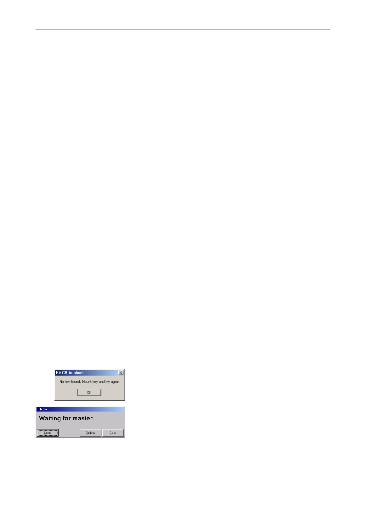
If the dongle is not inserted at startup, the “Hit CR to abort:” dialog box
opens (see “Starting the “Confsys”program for the first time” on
page 18).
If the dongle is inserted but cannot be detected due to the program
configuration, the “Waiting for master...” dialog box opens (see “Setting
the correct starting options” on page 19).
11
Page 12

Getting to know the software
Password 1 On delivery of the software, password 1 is: “123”.
Password 2 Password 2 is: “456”.
The two passwords
There are two passwords which limit the access to the software and the
configurations. Password 1 is required for changing the configuration.
Password 2 is required for initializating the conference consoles.
Note:
In order to ensure that only authorized persons can access the settings
of your conference and interpretation system, these passwords must
be changed as soon as possible (see “Changing the passwords of the
“Confsys” program” on page 21)!
12
Page 13

System requirements
System requirements
Hardware required
Processor: Intel Pentium 4 or AMD Athlon XP, 2 GHz or more
RAM: 256 MB min. (512 MB recommended)
Hard disk: min. 30 MB free hard disk memory
Drives: CD ROM or DVD ROM drive
drive for data backup (e.g. floppy disk drive,
CD recorder or ZIP drive)
Interfaces: at least one free RS 232 interface (see note below)
Sound card: quality stereo sound card
Screen resolution: exactly 1024
Network: optional 10/100/1000 Base Ethernet
Note on the RS 232 interfaces:
You only require one free RS 232 interface per PC if:
y you only control conference consoles via the software and not
interpreter consoles (you have not licensed the S-IM software
module),
y you use two different PCs to control the conference and
interpretation system (each PC has an RS 232 interface of its own),
y you use only one PC to control both the conference system and the
interpretation system and have to change the interface via which the
PC is connected to the central unit (the COM 3 interface of the central
unit to control the conference system and the COM 1 interface to
control the interpretation system).
You require two free RS 232 interfaces if:
y you want to use only one PC to control both the conference system
and the interpretation system without having to constantly change
the interface via which the PC is connected to the central unit.
Note on the screen resolution:
We recommend setting your screen resolution to exactly 1024
pixels!
× 768 pixels (see note below)
× 768
13
Page 14
System requirements
The operating system required
The SDC 8200 software requires Windows 2000 or Windows XP.
Note:
Both programs (“Confsys” to control the conference system and
“IntSys” to control the interpretation system) require one free COM
port each (RS 232 interface)! The SDC 8200 software therefore does
not function on PCs which do not have at least one free COM port not
assigned to another software – e.g. Hotsync (software for data transfer
between a PC and a Palm PDA)!
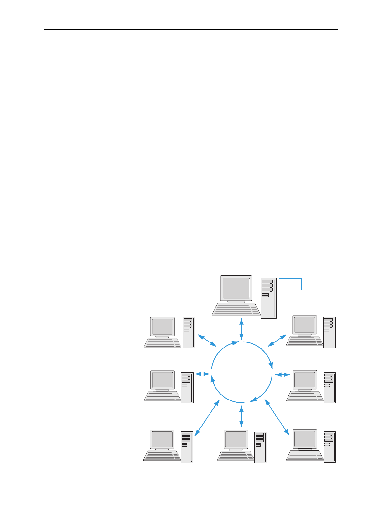
The network
You can install the software on up to eight PCs in a network. One of these
PCs must be configured as the “master” (see “Configuring the PC in a
network” on page 44). The master PC gives you access to all functions of
the conference and interpretation system. The dongle must be inserted
into a free USB port of the master PC.
Up to two PCs can be configured as “slaves” (see “Configuring the PC in a
network” on page 44). A slave PC also gives you access to all functions. The
slave PCs do not require a dongle.
Up to five PCs can be configured as “video PCs” (see “Configuring the PC in
a network” on page 44). A video PC does not give you access to the
functions of the conference and interpretation system. Projectors or
monitors connected to the video PCs are only for displaying data to the
delegates or guests. The video PCs do not require a dongle either.
Master
Slave
Dongle
Slave
LAN
Video
Video
14
Video
Video
Video
Page 15
Preparing the conference system for use
Preparing the conference system for use
Connecting the PC to the central unit
Please note that the program for controlling the conference system and
the program for controlling the interpretation system require a separate
RS 232 interface each.
The conference and interpretation system can be controlled using either
two PCs with one free RS 232 interface respectively or using one PC with
two free RS 232 interfaces.
You can connect additional Slave and Video PCs via a local area network
(LAN).
You must install the software on all the PCs.
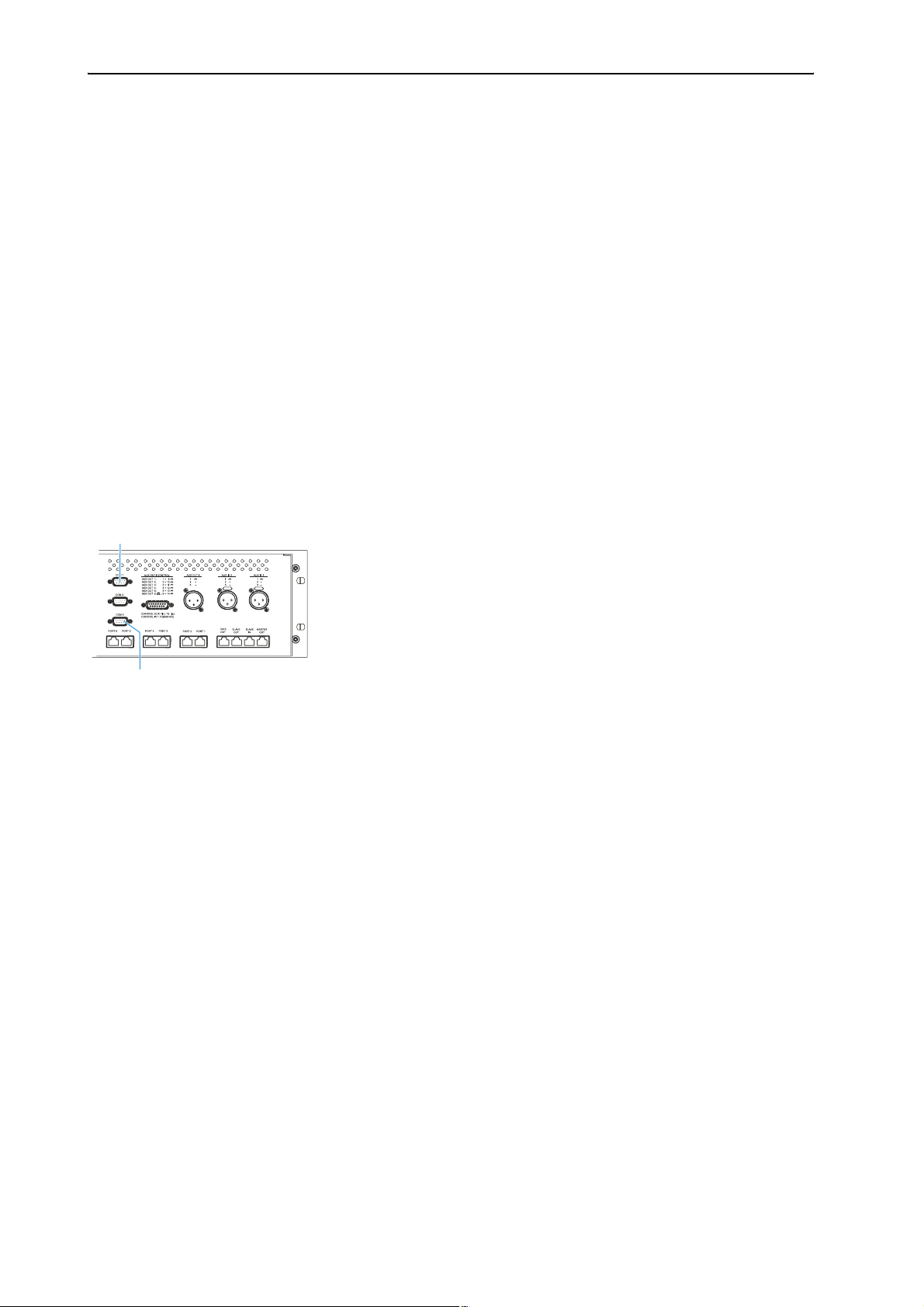
To connect PCs to the central unit:
왘 Make sure that the required serial interfaces are available and free. The
required interfaces must appear in the Windows Device Manager under
“Ports (COM & LPT)”. These interfaces must not be used by any other
software.
쐇
왘 Use one zero modem cable to connect the serial interface of the PC via
which the conference system is to be controlled to the COM 3
interface 쐇 of the central unit.
왘 Use the second zero modem cable to connect the serial interface of the
PC via which the interpretation system is to be controlled to the COM 1
interface 쐃 of the central unit.
Caution!
After you have connected the PC to the central unit, your conference
and interpretation system can be controlled via both the PC and the
central unit!
In order to avoid inconsistencies, please make sure that no parameters
are changed on the central unit!
15
Page 16
Preparing the conference system for use
Installing the software
To install the software on your PC or on different PCs in your network,
proceed as follows:
Attention! To avoid data loss, faulty installations and damage to the
dongle:
왘 Before installing the software, make a backup of all
your hard disk data!
왘 Remove all dongles from the PC, including those
required for other programs!
왘 Before installing a newer version of the software, first
de-install the older version as described on page 15!
왘 Make sure that your Windows user account has administrator
privileges.
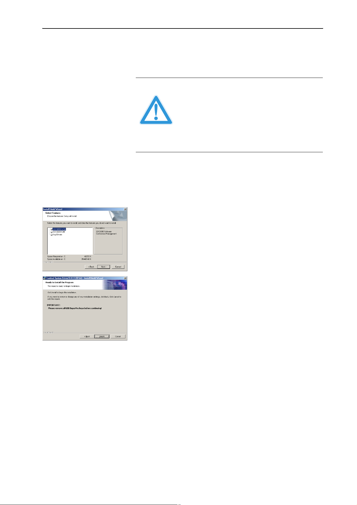
왘 Insert the software CD into the CD ROM drive of your PC and click the
“setup.exe” icon.
The Wizard starts and guides you through the installation process.
왘 Follow the instructions of the wizard and enter the installation path for
the programs. The rest of the installation is done automatically.
왘 After you have entered all information requested and started the
installation by clicking “Finish”, the desired software is installed on the
PC.
왘 When the software is installed, the dongle driver (Rainbow
Technologies Sentinel System Driver) is installed automatically. For
this, however, it is vital that no dongle is connected to the PC!
Note:
During the installation of the dongle driver, you can select either
“Complete” (all components including the help file) or “Custom”
(optionally without help file). We recommend selecting “Complete”.
After the installation is successfully completed, the newly installed
“SDC 8200” program group appears under “Start/Programs”. In the
“S_CM” subgroup, you will find the “Confsys” program for controlling
the conference system (see “Preparing the conference system for use”
on page 15); in the “S_IM” subgroup, you will find the “IntSys”
program for controlling the interpretation system (see “Configuring
the interpretation system” on page 91). In addition, you will find the
“Field Exchange Utility” utility program for upgrading your license (see
“Upgrading the software license” on page 108).
16
Page 17

Preparing the conference system for use
Removing the software
To remove the software from the hard disk of a PC:
왘 In the “Control Panel” window, click the “Add/Remove Programs” icon.
The “Add/Remove Programs” dialog box opens.
왘 On the left-hand side of the dialog box, click “Change or Remove
Programs”.
왘 Select “SDC8200” in the list and click the “Change/Remove” button.
A warning appears. Confirm the warning with “Yes”. The software is
removed from the PC.
왘 Select “Sentinel System Driver” in the list and click the “Change/
Remove” button.
A warning appears. Confirm the warning with “Yes”. The dongle driver
is removed from the PC.
17
Page 18
Starting the “Confsys”program for the first time
Starting the “Confsys”program for the
first time
When you start the “Confsys” program for the first time, the necessary
options for your PC or your network are not yet set.
왘 Make sure that your Windows user account has administrator
privileges.
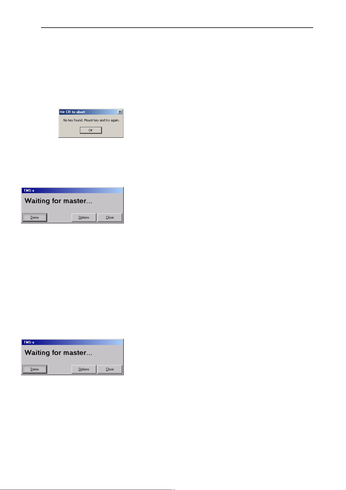
If the dongle is not inserted at startup or if it is removed during operation,
the “Hit CR to abort:” dialog box opens.
왘 In the “Hit CR to abort:” dialog box, click “OK”.
The “Waiting for master...” dialog box opens.
Note:
If the PC is configured as a video PC or slave PC and does not detect the
dongle at startup (because the master PC is turned off or the dongle is
not inserted into a free USB port of the master PC), the “Waiting for
master...” dialog box also opens.
The “Waiting for master...” dialog box offers you the following options:
1. You can close the “Waiting for master...” dialog box, insert the dongle
and restart the program (see “Connecting the dongle” on page 18).
2. You can click the “Options” button (password required!) and configure
the PC as a video PC or slave PC (see “Setting the correct starting
options” on page 19). To do so, you have to enter the TCP/IP address of
the master PC.
You then have to restart the program. The program searches for the
master PC with the inserted dongle. If the dongle is inserted into a free
USB port of the master PC and the master PC is turned on and the
program is running on the master PC, the program starts with the
selected configuration (video PC or slave PC).
3. You can start the program in demo mode (see “Starting the program in
demo mode” on page 20).
Connecting the dongle
To close the “Waiting for master...” dialog box:
왘 Click the “Close” button.
The “Waiting for master...” dialog box closes.
왘 Insert the dongle into a free USB port of the master PC.
18
왘 Restart the program.
Page 19

Starting the “Confsys”program for the first time
Setting the correct starting options
When you start the program for the first time, the “Waiting for master...”
dialog box appears and you have to decide whether the PC is to be
configured as a master PC, slave PC or video PC.
To do so, proceed as follows:
왘 Make sure that all PCs on which you have installed the software are
turned on and that the dongle is inserted into a free USB port of the
master PC.
왘 Make sure that “Full Control” is enabled for the installation folder (e.g.
C:\Programs\SDC8200) of the master PC
왘 In the “Waiting for master...” dialog box, click the “Options” button.
The “Options” window opens.
왘 On the “Confsys” tab, configure the PC as a master PC, slave PC or video
PC as required (see “Configuring the PC in a network” on page 44). On
the master PC and on all other PCs in the network, enter the correct IP
addresses of all PCs involved in the control of your conference and
interpretation system.
왘 If you only use one PC to control the conference and interpretation
system, configure this one as the master PC. In this case, you do not
require any IP addresses.
왘 On the “CU” tab, set the correct COM port (see “Configuring the COM
port” on page 49).
왘 In the “Options” window, click the ”Save and Exit” button. The
“Options” window closes.
왘 In the “Waiting for master...” dialog box, click the close “Close” button.
The dialog box closes.
왘 Restart the program. If you want to configure additional slave or video
PCs, proceed in the same way.
If the “Waiting for master...” dialog box appears when the program is
started for the second time (or later), this means that no connection can
be established with the master PC because:
y the master PC is not turned on or
y the “Confsys” program is not running on the master PC or
y “Full Control” is not enabled for the installation folder (e.g.
C:\Programs\SDC8200) of the master PC or
y the wrong IP address for the master PC was specified on the video or
slave PC or
y the wrong IP address for the video or slave PC was specified on the
master PC.
See also “If problems occur...” on page 110.
19
Page 20

Starting the “Confsys”program for the first time
Starting the program in demo mode
To start the Confsys program without a dongle:
왘 In the “Waiting for master...” dialog box, click the “Demo” button.
The program starts in demo mode.
Note:
Demo mode is started automatically when the dongle is removed
during operation.
In demo mode, your conference system is restricted to five delegates
and your interpretation system is restricted to two languages with only
one interpreter per language, this means in detail:
y You can configure conferences with more than five conference
y You can open conference configurations with more than five
y During a conference, only the first five conference consoles are
y You can only configure two interpreter booths with one interpreter
y You can open interpretation configurations with more than two
y When transmitting the interpretation configuration to the central
consoles, but only the first five conference consoles are stored.
conference consoles, but only the first five conference consoles are
displayed.
displayed.
console each.
interpreter booths and more than one interpreter console per booth,
but only the first two booths with their respective first interpreter
console are displayed.
unit, only the first two interpreter booths with their respective first
interpreter console are taken into account.
20
Page 21
Adjusting important basic settings
Adjusting important basic settings
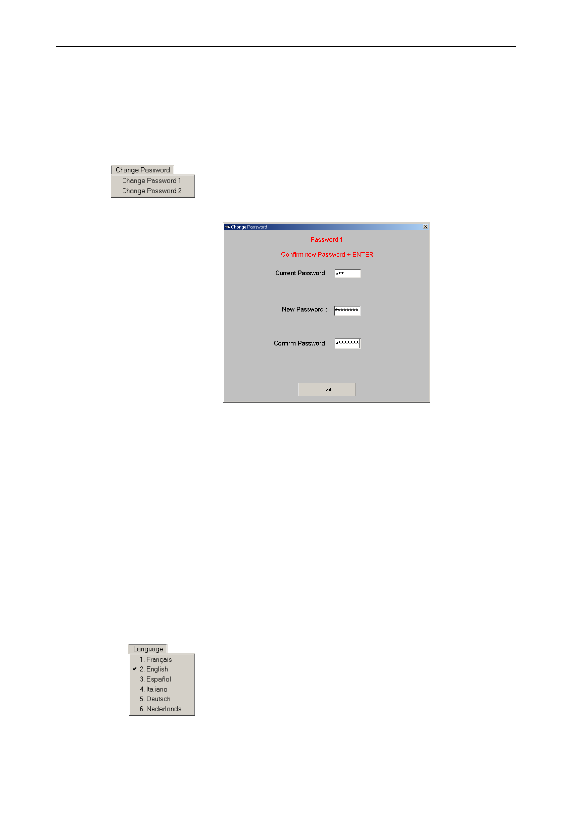
Changing the passwords of the “Confsys” program
To change the passwords:
왘 From the “Change Password” menu, choose “Change Password 1” to
change the password 1 or choose “Change Password 2” to change the
password 2.
The “Change Password” dialog box opens.
왘 In the “Current Password” box, enter the current password (see “The
two passwords” on page 12) and press the “Enter” key.
The “New Password” box appears.
왘 In the “New Password” box, enter the new password (eight characters
max.) and press the “Enter” key.
The “Confirm Password” box appears.
왘 In the “Confirm Password” box, re-enter the new password and press
the “Enter” key.
The “Save” and “Cancel” buttons appear.
왘 Click the “Save” button to save the new password; click the “Cancel”,
button to keep the current password.
Changing the menu language of the “Confsys” program
To change the menu language:
왘 From the “Language” menu, choose the desired language.
The menu language is changed immediately.
21
Page 22
Configuring the conference system
Configuring the conference system
This chapter provides information on how to quickly and easily configure
the consoles of your conference system (but not the consoles of the
interpretation system) using the software.
For configuring the conference system, you require the S-MM (Microphone
Management) software module which is started as follows:
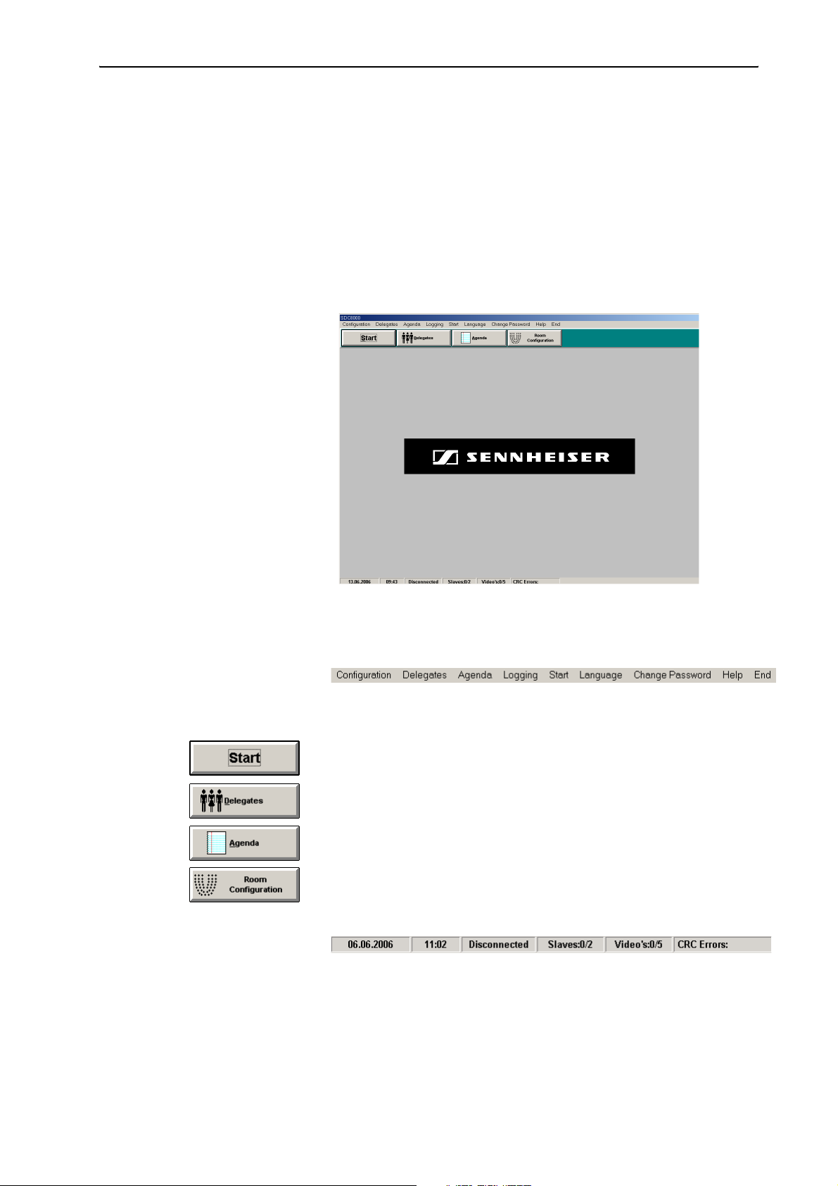
왘 Click “Start” and select “Programs”, “SDC 8200” and “S_CM” one after
the other. Then click “Confsys”.
The “SDC 8200” window opens.
The “SDC 8200” window consists of:
y the menu bar
If you have not licensed all of the software modules, some of the menus
will not be available in your software.
y the “Start” button
for starting an already existing conference configuration
y the “Delegates” button
for opening an editing the delegate database,
y the “Agenda” button
for opening and editing the agenda,
y the “Room Configuration” button
for opening and editing the synoptic view
y the status bar
which shows the current date, the current time and the state of the COM
connection to the central unit (“Connected” or “Disconnected”). In
addition, the number of slave and video PCs connected to the master PC
and the communication errors between the SDC 8200 CU central unit and
the master PC are displayed.
22
Page 23
Configuring the conference system
Creating a synoptic view of the conference
For monitoring a conference as well as for intervening in a conference at
any time, you require a synoptic view of the conference room. In this
synoptic view, each conference console is represented by an icon.
This synoptic view can be “wallpapered” with a background picture (e.g. a
picture of the conference room). If you then position the conference
console icons exactly where the delegates are seated, you obtain an
intuitively operable conference system.
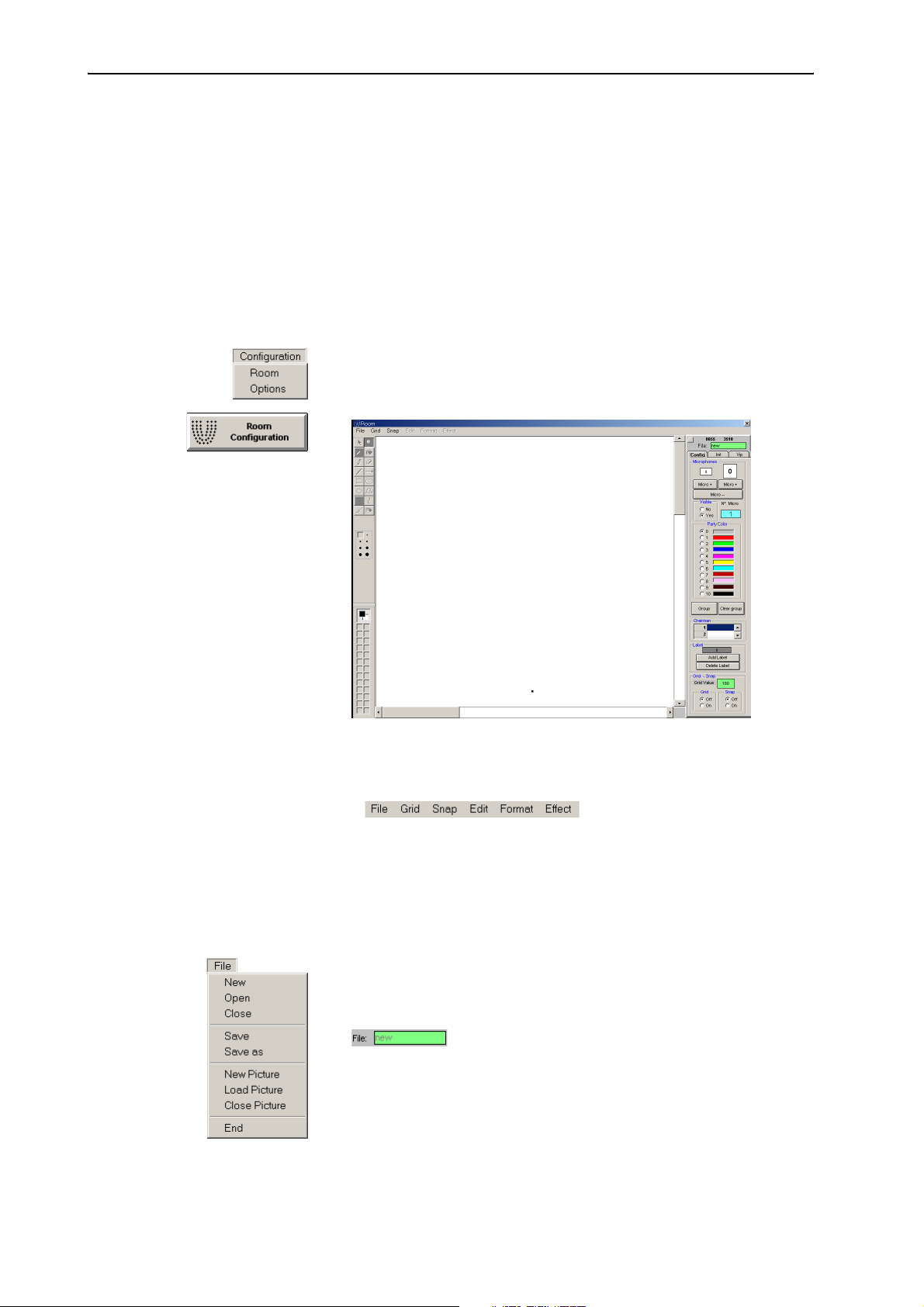
Creating a synoptic view file
왘 From the “Configuration” menu, choose “Room” or click the “Room
Configuration” button in the “SDC 8200” window.
The “Room” window opens.
The “Room” window consists of:
y the menu bar,
y the “Config”, “Init” and “Vip” tabs on the right-hand side of the
window
y the canvas for displaying and editing the synoptic view
y the display of the current mouse pointer coordinates on the canvas
as well as the green “File” box for the file name (above the tabs)
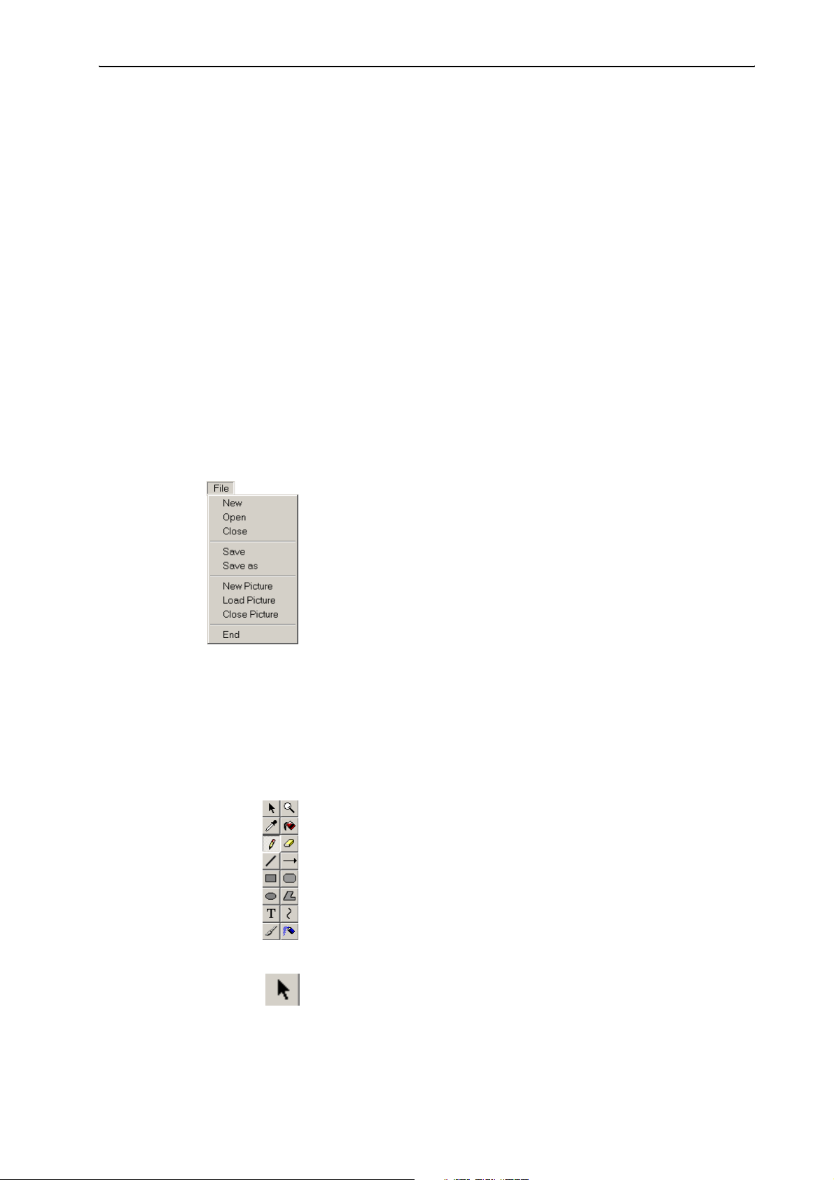
왘 From the “File” menu, choose “New”.
The main window turns white and the “Config”, “Init” and “Vip” tabs
become active. “new” is displayed in the green “File” box.
The drawing palette is not active. The drawing palette becomes active
when you have added a background picture to the synoptic view (see
“To create a new background picture for a synoptic view:” on page 24
or “To open an existing background picture for a synoptic view:” on
page 24).
23
Page 24
Configuring the conference system
You can now
y create a synoptic view (see “Positioning new conference console icons”
on page 30).
y add a background picture to an existing synopic view. We recommend
that you first add the background picture of the conference room and
then position the conference console icons.
To save a synoptic view file:
왘 From the “File” menu, choose “Save” or choose “Save as” to save the
synoptic view under a new name or in a different folder.
To open a previously created and saved synoptic view file:
왘 From the “File” menu, choose “Open” and select the desired *.tec file.
The selected synoptic view appears in the main window and the file
name is displayed in the green “File” box.
To close a synoptic view file without saving it:
왘 From the “File” menu, choose “Close”.
The file is closed.
To create a new background picture for a synoptic view:
왘 From the “File” menu, choose “New Picure”.
An empty background picture opens and you can add the drawing
objects to the picture.
To open an existing background picture for a synoptic view:
왘 From the “File” menu, choose “Load Picture” and choose the desired
backgound picture (format: *.jpg, *.bmp, *.gif or *.fig).
The background picture opens and you can add the drawing objects to
the picture.
To close the background picture:
왘 From the “File” menu, choose “Close Picture”.
The background picture is closed. The added conference console icons
and icon labels are retained in the synoptic view.
Editing the background picture To add drawing objects to the background picture:
왘 Create a new background picture
or open an existing background picture.
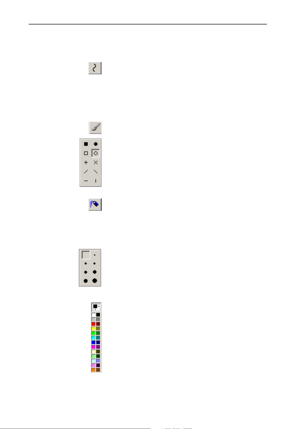
왘 Use the drawing palette.
The drawing palette works like a simple drawing program.
24
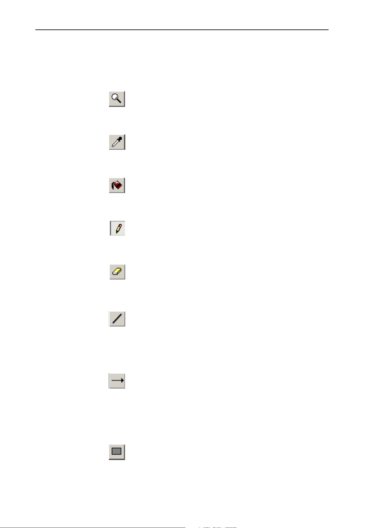
To select an object or area:
왘 In the drawing palette, click the “Select Area” icon.
왘 Position the mouse pointer on the starting point of the selection
rectangle, then click and hold down the left mouse button.
Page 25
Configuring the conference system
왘 Drag the mouse pointer to the desired size of the selection rectangle
and release the mouse button.
The selected object or area can be moved with the mouse or copied
using th“copy” command.
To enlarge the background picture:
왘 In the drawing palette, click the “Zoom” icon.
왘 Click the picture.
The picture is enlarged.
To pick a new foreground color:
왘 In the drawing palette, click the “Pick color” icon.
왘 Click the mouse pointer in the desired foreground color.
The color is picked as the new foreground color.
To fill an object/area with color:
왘 In the drawing palette, click the “Fill” icon.
왘 Click the object/area you want to fill with the selected foreground color.
The object/area is filled with the selected foreground color.
To draw with the freeform pencil tool:
왘 In the drawing palette, click the “Pencil” icon.
왘 Use the mouse pointer to draw as if you were drawing with a pencil on
paper.
To erase objects or areas:
왘 In the drawing palette, click the “Eraser” icon.
왘 Click and hold down the left mouse button.
왘 Move the mouse pointer over the objects or areas you want to erase.
To draw a straight line:
왘 In the drawing palette, click the “Line” icon.
왘 Position the mouse pointer where you want to begin to draw the line,
then click and hold down the left mouse button.
왘 Drag the mouse pointer to the desired endpoint of the line and release
the mouse button.
To draw an arrow:
왘 In the drawing palette, click the “Arrow” icon.
The arrow head appears where you release the mouse button.
왘 Position the mouse pointer where you want to begin to draw an arrow,
then click and hold down the left mouse button.
왘 Drag the mouse pointer to the desired endpoint of the arrow and
release the mouse button.
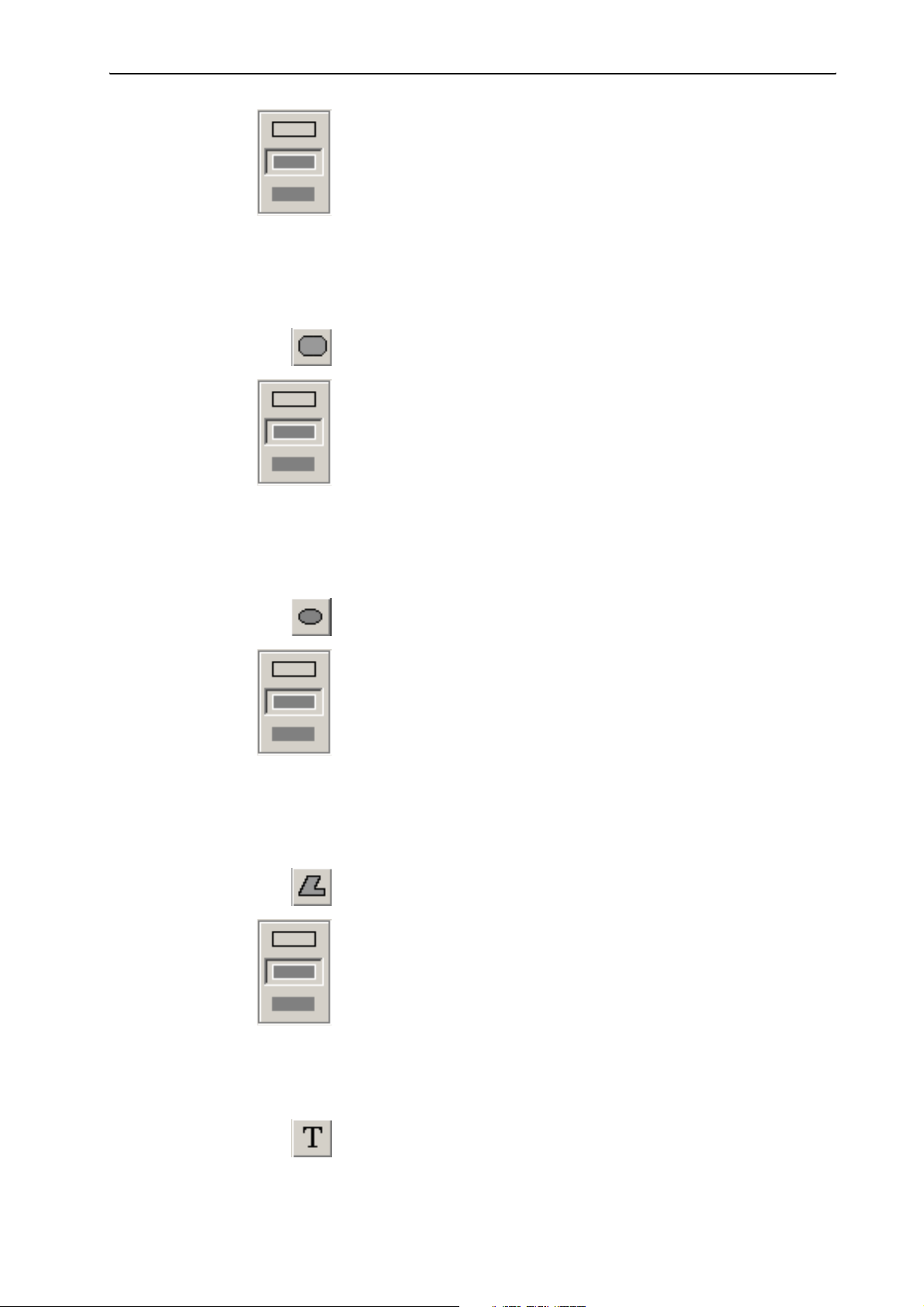
To draw a rectangle:
왘 In the drawing palette, click the “Rectangle” icon.
왘 Select the desired fill style.
25
Page 26
Configuring the conference system
y Border: foreground color; interior: colorless
y Border: foreground color; interior: background color
y Border: colorless; interior: background color
왘 Position the mouse pointer on the starting point of the rectangle, then
click and hold down the left mouse button.
To draw a square, hold down SHIFT key while drawing.
왘 Drag the mouse pointer to the desired size of the rectangle and release
the mouse button.
To draw a rounded rectangle:
왘 In the drawing palette, click the “Rounded Rectangle” icon.
왘 Select the desired fill style.
y Border: foreground color; interior: colorless
y Border: foreground color; interior: background color
y Border: colorless; interior: background color
왘 Position the mouse pointer on the starting point of the rounded
rectangle, then click and hold down the left mouse button.
To draw a rounded square, hold down SHIFT key while drawing.
왘 Drag the mouse pointer to the desired size of the rounded rectangle
and release the mouse button.
To draw an ellipse or a circle:
왘 In the drawing palette, click the “Ellipse” icon.
왘 Select the desired fill style.
y Border: foreground color; interior: colorless
y Border: foreground color; interior: background color
y Border: colorless; interior: background color
왘 Position the mouse pointer on the starting point of the ellipse, then
click and hold down the left mouse button.
To draw a cicle, hold down SHIFT key while drawing.
왘 Drag the mouse pointer to the desired size of the ellipse and release the
mouse button.
To draw a polygon:
왘 In the drawing palette, click the “Polygon” icon.
왘 Select the desired fill style.
y Border: foreground color; interior: colorless
y Border: foreground color; interior: background color
y Border: colorless; interior: background color
26
왘 Position the mouse pointer on the starting point of the polygon, then
click and hold down the left mouse button.
왘 Click the next points of the polygon and double-click to close the
polygon.
To enter text:
왘 In the drawing palette, click the “Text” icon.
왘 Select the desired font for the text.
Page 27
Configuring the conference system
왘 Click the desired starting point of the text.
You can only enter one line of text.
To draw a curve:
왘 In the drawing palette, click the “Curve” icon.
왘 Click the canvas.
A curve is drawn.
왘 Move the starting and endpoint of the curve.
왘 Move the little squares.
The slope of the curve is changed.
To paint with the brush:
왘 In the drawing palette, click the “Brush” icon.
왘 Select the desired brush stroke width.
왘 Select the desired brush tip shape.
왘 Position the mouse pointer on the canvas, then click and hold down the
left mouse button.
왘 Drag the mouse pointer to paint with the brush and release the mouse
button.
To paint with the airbrush:
왘 In the drawing palette, click the “Airbrush” icon.
왘 Position the mouse pointer on the canvas, then click and hold down the
left mouse button.
왘 Drag the mouse pointer to paint with the airbrush and release the
mouse button.
To select the stroke width:
왘 In the “Stroke width” palette, click the desired stroke width.
Note:
The “Stroke width” palette only appears after you have click a certain
icon (e.g. “Select Area“ or “Zoom“) on the drawing palette.
To assign colors:
The two uppermost color boxes on the color palette display the foreground
and the background color.
To change the foreground color:
왘 If the foreground color box is selected, select a new foreground color
from the color palette.
The foreground color is changed.
Or:
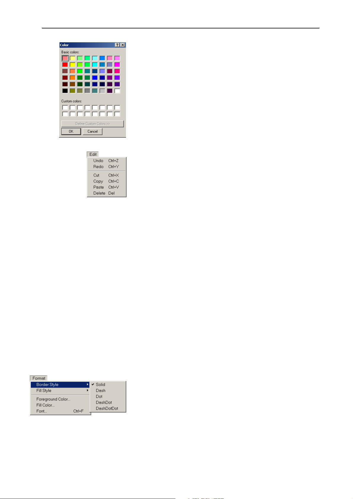
왘 In the color palette, double-click the foreground color box (shown in
black in the example screenshot).
The “Color” window opens.
27
Page 28
Configuring the conference system
왘 In the “Color” window, click the desired color or define your own color.
The foreground color is changed.
To change the background color:
왘 In the color palette, double-click the background color box (shown in
white in the example screenshot).
The “Color” window opens.
왘 In the “Color” window, click the desired color or define your own color.
The background color is changed.
To undo the last drawing operation:
왘 From the “Edit” menu, choose “Undo“
or press the key combination Ctrl + Z .
The last drawing operation is undone.
To redo the last undone drawing operation:
왘 From the “Edit” menu, choose “Redo“
or press the key combination Ctrl + Y.
The last undone drawing operation is redone.
To cut a selected area:
왘 From the “Edit” menu, choose “Cut“
or press the key combination Ctrl + X.
The selected area is cut and saved on the clipboard.
To copy the selected area to the clipboard:
왘 From the “Edit” menu, choose “Copy“
or press the key combination Ctrl + C.
The selected area is copied to the clipboard.
To paste the cut or copied area from the clipboard onto the canvas:
왘 From the “Edit” menu, choose “Paste“
or press the key combination Ctrl + “V”.
The cut or copied area is pasted to the upper left corner of the canvas.
To delete the selected area:
왘 From the “Edit” menu, choose “Delete“
or press the “Del” key.
The selected area is deleted.
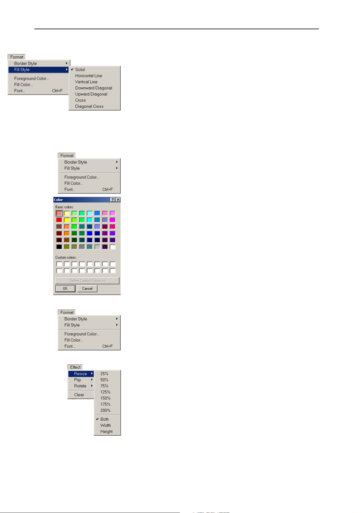
To set the border style for a drawing object:
왘 From the “Format” menu, choose “Border Style”.
Set the border style of a drawing object.
y Solid: solid line
y Dash: dashed line
y Dot: dotted line
y DashDot: dashdot line
y DashDotDot: dashdotdot line
28
Page 29
Configuring the conference system
To set the fill style for a drawing object:
왘 From the “Format” menu, choose “Fill Style”.
Set the fill style of a drawing object.
y Solid: solid fill
y Horizontal Line: horiziontal lines
y Vertical Line: vertical lines
y Downward Diagonal: downward diagonal lines
y Upward Diagonal: upward diagonal lines
y Cross: horizontal and vertical cross lines
y Diagonal Cross: diagonally crossed lines
To set a foreground color for drawing objects:
왘 From the “Format” menu, choose “Foreground Color”.
The color palette opens.
왘 Set the foreground color for drawing objects by clicking the desired
color on the color palette or define your own color.
To set a fill color for drawing objects:
왘 From the “Format” menu, choose “Fill Color”.
The color palette opens.
왘 Set the fill color for drawing objects by clicking the desired color on the
color palette or define your own color.
To select the font type for a text object:
왘 From the “Format” menu, choose “Font”.
A window for selecting the font type appears.
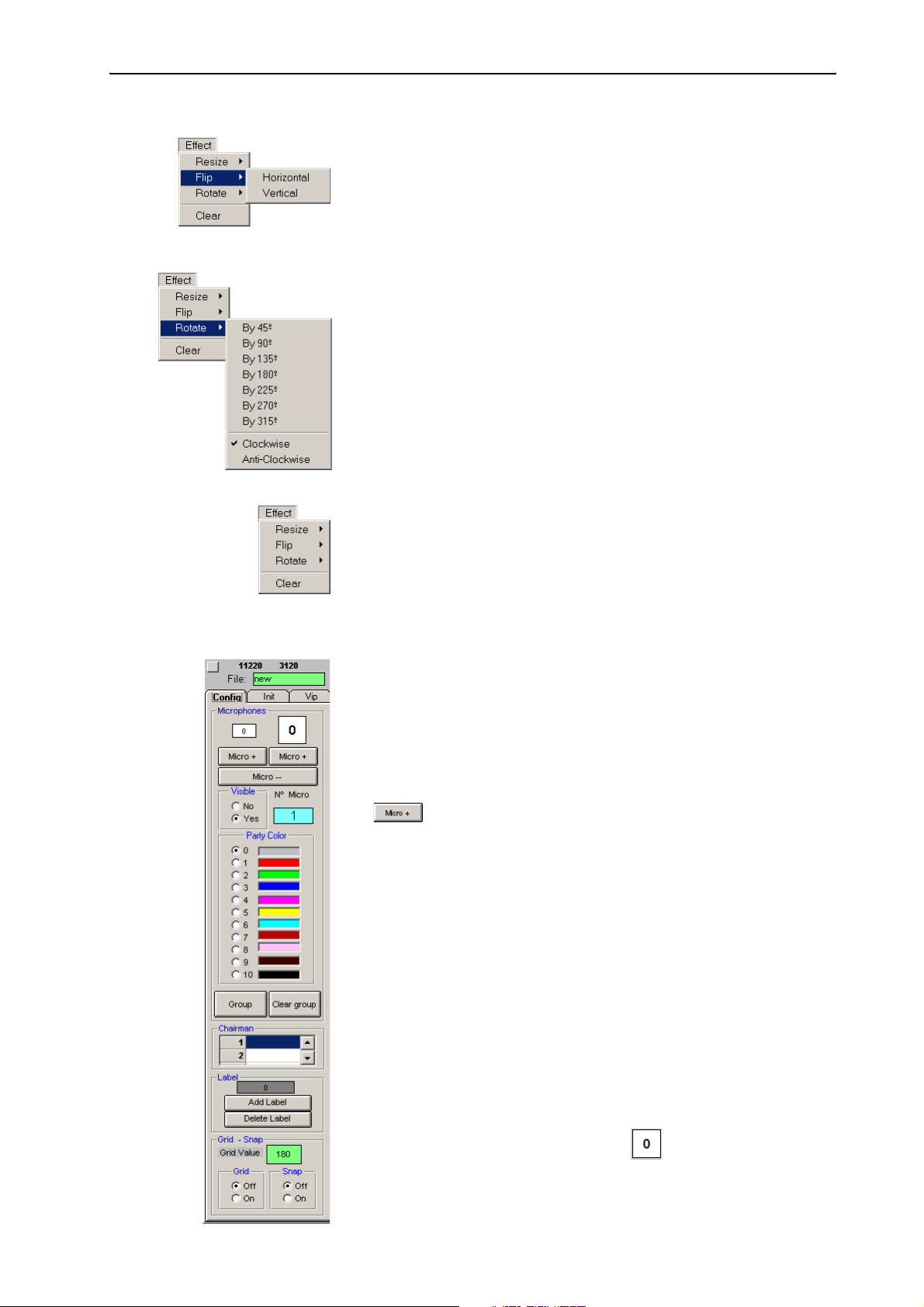
To resize the background picture:
왘 From the “Effect” menu, choose “Resize”.
왘 Select the scaling type.
y Both: the aspect ratio is kept constant
y Width: scales the width of the picture
y Height: scales the height of the picture
왘 Select the desired scaling factor (in percent).
The background picture is resized and the drawing object are either
streched or compressed.
29
Page 30
Configuring the conference system
To flip the background picture:
왘 From the “Effect” menu, choose “Flip”.
왘 Select the desired flipping axis.
y Horizontal: flips the picture horizontally, along the vertical axis
y Vertical: flips the picture vertically, along the horizontal axis
To rotate the background picture:
왘 From the “Effect” menu, choose “Rotate”.
왘 Select the rotating direction.
y Clockwise: rotates the picture clockwise
y Anti-Clockwise: rotates the picture anti-clockwise
왘 Select the desired rotation angle.
The background picture is rotated by the selected angle.
To delete the background picture and the drawing objects:
왘 From the “Effect” menu, choose “Clear”.
The background picture and the drawing objects are deleted.
The synoptic view remains unchanged.
Positioning new conference console icons
To add a conference console icon:
왘 In the “Party Color” box on the “Config” tab, click the color for the
conference console icon.
You can change this color at any time by clicking the conference console
icon and then clicking another color in the “Party Color” box.
왘 Click one of the two “Micro +” buttons.
Clicking the left “Micro +” button adds a small icon, clicking the right
“Micro +” button adds a large icon.
The icon appears in the upper left corner of the window. If you click one
of the two “Micro +” buttons several times in succession, the icons
appear side-by-side in the upper left corner of the window.
The conference console icons are automatically assigned a provisional
microphone number which is displayed both on the icon and in the
“N° Micro” field. The icon with the provisional microphone number “1”
is configured as the chairman unit. You can, however, configure any
other conference console as the chairman unit at any time, i.e. before
(see “Defining the console icon for the chairman unit” on page 33) or
during a conference (see “Configuring the chairman unit during a
conference” on page 73).
30
Or:
왘 Drag the conference console icon, e.g. , from the “Config” tab to
the desired location.
The provisional microphone number is assigned.
Page 31

Configuring the conference system
To move conference console icons to a new location:
왘 Click the icon to be moved and hold down the left mouse button. While
you are still holding down the mouse button, move the icon to the
desired location.
To exactly align conference console icons with the grid:
왘 In the “Grid” box on the “Config” tab, click the “On” option button or
choose “Grid on” from the “Grid” menu.
The grid is displayed.
왘 Click the green “Grid Value” field, enter the desired distance between
the grid lines and press the “Enter” key.
The distance between the grid lines is changed.
The distance between the grid lines should be large enough to allow a
console icon to fit comfortably between them (“Grid Value” approx.
“750” to “1750”).
왘 In the “Snap” box on the “Config” tab, click the “On” option button or
choose “Snap On” from the “Snap” menu.
왘 Move an icon close to a grid line intersection. When releasing the mouse
button, the icon will automatically snap to the grid line intersection.
The icons are also aligned with the grid when the grid itself is hidden
but the “Snap” option is activated.
To delete a conference console icon:
왘 Click the “Micro --” button.
The last icon added is deleted.
If you click the “Micro --” button several times in succession, the last
icons added are deleted one after the other.
To enlarge/reduce the size of a conference console icon:
왘 Press the “Ctrl” key and keep it pressed.
왘 Click the conference console icon (several times).
The size of the conference console icon is changed. Each click changes
the size from small via medium to large.
Editing all conference console icons simultaneously
You can edit all conference console icons simultaneously, e.g. you can
y move them to a new location,
y enlarge/reduce their size,
y change the spacing between them or,
y flip them horizontally or vertically.
To simultaneously edit all conference console icons:
왘 Click the empty square button at the left above the “Config” tab.
31
Page 32

Configuring the conference system
The dialog box shown on the left opens.
To move all conference console icons to a new location:
왘 In the “X (Hor)” field, enter the number of pixels by which all
conference console icons are to be moved horizontally. Negative values
will move the icons to the left, positive values will move all icons to the
right.
왘 In the “Y (Vert)” field, enter the number of pixels by which all
conference console icons are to be moved vertically.
왘 Click the “Apply” button next to the “X (Hor)” and “Y (Vert)” fields.
All icons are moved by the number of pixels entered.
To change the size of all conference console icons:
왘 In the “Microphone size” box, click the “Normal”, “Big” or “Extra big”
option button.
왘 Click the “Apply” button next to the “Normal”, “Big” and “Extra big”
options buttons.
The size of all icons is changed. Please note, however, that the spacing
between the icons is NOT changed.
To move all conference console icons by flipping them horizontally or
vertically:
왘 In the “X-ax (Hor)” field, enter the position of the horizontal axis along
which the icons are to be flipped. At a value of 8200, the axis runs
horizontally through the center of the image.
왘 Click the “Apply” button next to the “X-ax (Hor)” field.
All icons are flipped along the selected axis.
왘 In the “Y-ax (Vert)” field, enter the position of the vertical axis along
which the icons are to be flipped. At a value of 8200, the axis runs
vertically through the center of the image.
왘 Click the “Apply” button next to the “Y-ax (Vert)” field.
All icons are flipped along the selected axis.
To change the spacing between the conference console icons:
왘 In the “Scale %” field, enter the value for the desired distance between
the icons. Values above 100% will increase the distance, values below
100% will reduce the distance.
왘 Click the “Apply” button next to the “Scale %” field.
The distance between the icons is changed.
To exit the dialog box without editing the conference console icons:
왘 Click “Cancel”.
The dialog box closes.
32
Hiding conference console icons
If a certain conference console is not being used during a conference, you
can hide the corresponding icon as follows:
왘 Click the icon to be hidden.
Page 33

Configuring the conference system
왘 In the “Visible” box on the “Config” tab, click the “No” option button.
The icon turns orange (exception: the icon of the chairman unit is
always pink). When you start the conference, this icon is invisible.
To make a hidden icon visible again:
왘 In the “Visible” box on the “Config” tab, click the “Yes” option button.
The original color of the icon is restored. When you start the
conference, this icon is visible again.
Creating an icon label
To add a short label to the conference console icon:
왘 In the “Label” box on the “Config” tab, click the “Add Label” button .
The label appears in the upper left corner of the window. If you click the
“Add Label” button several times in succession, the labels appear one
above the other and you can only edit the uppermost label.
Or:
왘 Drag the icon label from the “Config” tab to the desired
location.
왘 Enter the desired text.
You can enter a maximum of nine characters.
You can automatically add the icon labels (see “Labelling conference
console icons automatically” on page46). For this, you must have a
delegate list (see “Entering delegate data” on page 51).
To move and align an icon label:
왘 Proceed as described for the console icons.
To delete an icon label:
왘 Click the “Delete Label” button.
The last icon label added is deleted.
If you click the “Delete Label” button several times in succession, the
last icon labels added are deleted one after the other.
Defining the console icon for the chairman unit
Chairman units provide you with certain rights and privileges:
y If the chairman presses the microphone key 씊, he can take the floor
immediately without first having to make a request to speak.
y If the chairman presses the priority key 쐈, all active conference con-
soles – except for the VIP units – are turned off.
y If the chairman presses the NEXT key 씌, he assigns the “speaking
right” to the next participant who has made a request to speak (only in
“With Request” or “With Req. No Clear” mode).
To define a certain console icon as the icon for the chairman unit:
왘 In the “Chairman” box on the “Config” tab, click one of the rows in the
table of chairman units.
The button for opening the drop down list appears.
33
Page 34

Configuring the conference system
왘 Click the drop down list and select the provisional microphone number
of the chairman unit. You can configure as many chairman units as you
want.
The console icon with the corresponding number turns pink. When you
start the conference, this conference console is configured as the
chairman unit.
You can change this configuration at any time during the conference
(see “Configuring the chairman unit during a conference” on page 73).
Note:
Make sure that only conference consoles which feature a priority
key 쐈 (SDC 8200 C, SDC 8200 CC or SDC 8200 CV) are configured as
a chairman unit!
Defining groups
The software for the SDC 8200 conference system allows you to combine
certain conference consoles in groups. There are two types of groups:
y Audio groups allow you to preselect different audio settings for different
participant groups. You can, for example, set the volume of the built-in
loudspeakers of all conference consoles assigned to a certain group
higher or lower than the volume of the built-in loudspeakers of the other
conference consoles.
y Voting groups allow you to restrict the participation in votes to certain
participant groups.
Notes!
You can define a maximum of 20 groups. One group can comprise a
minimum of one and a maximum of all conference consoles. Delegate
units, VIP units and chairman units can be arbitrarily mixed in one
group.
Each conference console can only be assigned to a single audio group
and a single voting group at a time, i.e. one conference console cannot
be assigned simultaneously to several audio groups or voting groups.
To define an audio group:
왘 Press the “Ctrl” key and keep it pressed.
왘 Right-click the first conference console which is to be added to the
audio group.
The dialog box for editing groups opens.
왘 From the “Audio Group” drop down list, choose the number to be
assigned to the audio group. This number must be higher than “01“!
왘 In the “Description” field, enter an unambiguous description of the
audio group.
왘 Click the “Change” button next to the “Description” field and choose a
group color for the audio group from the color palette.
왘 Click “OK”.
An audio group with the selected number and description is created
and the conference console is added to the newly created audio group.
In addition, a standard audio group “01” is created automatically. All
conference console which are not added to an audio group with a
number higher than “01” are automatically added to the standard
audio group “01”.
34
Page 35

Configuring the conference system
To define a voting group:
왘 Press the “Ctrl” key and keep it pressed.
왘 Right-click the first conference console which is to be added to the
voting group.
The dialog box for editing groups opens.
왘 From the “Vote Group” drop down list, choose the number to be
assigned to the voting group. This number must be higher than “01“!
왘 In the “Description” field, enter an unambiguous description of the
voting group.
왘 Click the “Change” button next to the “Description” field and choose a
group color for the voting group from the color palette.
왘 Click “OK”.
A voting group with the selected number and description is created and
the conference console is added to the newly created voting group.
In addition, a standard voting group “01” is created automatically. All
conference console which are not added to a voting group with a
number higher than “01” are automatically added to the standard
voting group “01”.
Adding a conference console to a group
To add a conference console to an existing group:
왘 Press the “Ctrl” key and keep it pressed.
왘 Right-click the conference console which is to be added to a group.
The dialog box for editing groups opens.
왘 From the “Audio Group” drop down list, choose the number of the
audio group to which the conference console is to be added and/or
from the “Vote Group” drop down list, choose the number of the voting
group to which the conference console is to be added.
The description of the selected group and the group color are displayed.
(You can edit the description and the group color as described under
“Defining groups” on page 34.)
왘 Click “OK”.
The conference console is added to the group.
Removing a conference console from a group
To remove a conference console from an exisitng group:
왘 Press the “Ctrl” key and keep it pressed.
왘 Right-click the conference console which is to be removed from a group.
The dialog box for editing groups opens. The number, the description
and the group color of the assigned audio group and voting group are
displayed. (You can edit the description and the group color as
described under “Defining groups” on page 34.)
왘 To remove a conference console from an audio group, choose the
number “01” from the “Audio Group” drop down list; to remove a
conference console from a voting group, choose the “01” from the
“Vote Group” drop down list.
왘 Click “OK”.
The conference console is removed from the group.
35
Page 36

Configuring the conference system
Displaying the overview of groups
To display to assignment of a conference console to an audio group or a
voting group:
왘 On the “Config” tab, click the “Group” button.
The “Group Overview” dialog box opens.
왘 From one of the two drop down lists “Audio Group” or “Vote Group”,
choose the number of the group to be displayed.
The description of the selected group and the group color are displayed.
(You cannot edit the description and the group color in this dialog box.)
In addition, the provisional microphone numbers of all conference
consoles assigned to the selected group are displayed in the
“Members” list.
왘 Click the “Show” button.
In the “Room” window, all conference consoles assigned to the selected
group are highlighted in the group color of the group.
To return to the normal display:
왘 In the “Group Overview” dialog box, click the “Close” button.
All conference consoles are displayed in their original color instead of
the group color.
Configuring VIP units
VIP units are delegate units with special “rights” and privileges:
y With a VIP unit, you can take the floor at any time by pressing the
microphone key 씊, regardless of the conference mode and without
first having to be assigned the “speaking right”.
y If the chairman presses the priority key 쐈, all active conference
consoles – except for the VIP units – are turned off. The chairman cannot
withdraw the “speaking right” from you.
To assign the VIP status to a conference console:
왘 Make sure that the “VIP enabled” check box on the “Vip” tab shows a
tick.
왘 On the “Vip” tab, click one of the rows in the table of VIP units.
The button for opening the drop down list appears.
왘 Click the drop down list and select the provisional microphone number
of the VIP unit. You can configureup to ten VIP units.
During a conference, VIP units are marked with a blue square in the upper
left corner of the conference console icon. During a conference, these blue
squares can be displayed or hidden by clicking the “VIP: ON” button in the
tool palette.
36
To withdraw the VIP status from a conference console:
왘 On the “Vip” tab, click the row with the VIP unit to be removed in the
table of VIP units.
The button for opening the drop down list appears.
왘 Press the DELETE key.
The VIP unit is removed from the table.
Page 37
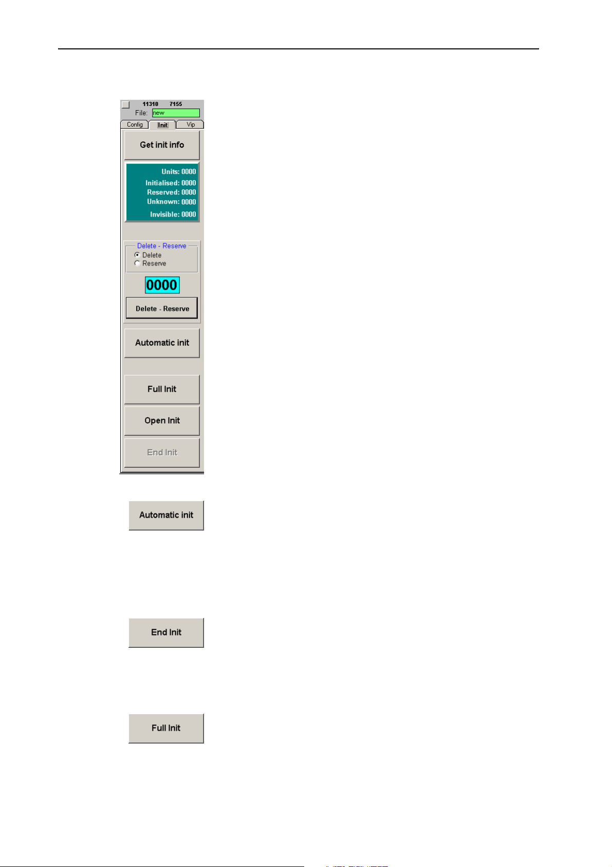
Configuring the conference system
Initializing the conference consoles
After you have created a synoptic view of the conference, you have to
assign a real conference console to each console icon of the synoptic view.
To do so, you have to either automatically or manually initialize the
conference consoles:
y When performing an automatic initialization, the microphone numbers
are assigned in an arbitrary order.
y When performing a manual initialization, the microphone numbers are
assigned in a certain order. If your synoptic view comprises icon labels
showing the names of the delegates, you should perform a manual
initalization.
Before starting the initialization:
왘 Make sure that
y an icon is created for each conference console,
y all conference consoles are connected correctly and
y the central unit is turned on.
To initialize the conference consoles:
왘 Click the “Init” tab.
The “Init” tab appears in front of the “Room” window.
To automatically initialize the conference consoles:
왘 On the “Init” tab, click the “Automatic Init” button. In the “Start
Initialisation?” dialog box that opens, click “Yes”.
All conference consoles are initialized automatically. The icons of
correctly initialized conference consoles are displayed in green in the
synoptic view. Please note that “invisible” conference console icons are
also assigned a microphone number.
All consoles with a display panel display the microphone number which
does not correspond to the provisional microphone number displayed
on the conference console icon!
왘 When all icons in the synoptic view are displayed in green and “0”
appears behind “Unknown” in the green Info box, click the “End Init”
button.
왘 Save this configuration by choosing “Save” from the “File” menu.
Your conference system is now ready for operation.
To manually initialize the conference consoles:
왘 On the “Init” tab, click the “Full Init” button. In the “Start
Initialisation?” dialog box that opens, click “Yes”.
The signal lights rings of all connected conference consoles start
flashing.
37
Page 38

Configuring the conference system
왘 One after the other, press the microphone key 씊 on all conference
consoles in exactly the order in which the conference console icons in
the synoptic view are numbered!
The signal light ring goes off and the conference console icon is
displayed in green. The conference consoles are assigned sequential
microphone numbers in exactly the order in which you press the
microphone key 씊.
왘 When all icons in the synoptic view are displayed in green and “0”
appears behind “Unknown” in the green Info box, click the “End Init”
button.
왘 Save this configuration by choosing “Save” from the “File” menu.
Your conference system is now ready for operation.
Changing an assigned microphone number
If some conference consoles were not initialized in the desired order, the
synoptic view does not agree with the real configuration. However, you
can assign a certain conference console a new microphone number by first
deleting the current microphone number and then assigning a new one.
To delete an assigned microphone number:
왘 On the “Init” tab, click the “Open Init” button. In the “Start
Initialisation?” dialog box that opens, click “Yes”.
왘 In the “Delete – Reserve” box, click the “Delete” option button.
왘 Click the “0000” field and enter the four-digit microphone number you
want to delete.
왘 Click the “Delete – Reserve” button.
The conference console icon with the previously entered microphone
number turns light-blue and the signal light ring of the corresponding
conference console starts flashing.
You can assign this conference console a new microphone number by
pressing the microphone key 씊.
왘 Click the “End Init” button.
The conference console with the previously entered microphone
number is deinitialized. If this consoles has a display panel, the text
“Init refused” is displayed. You then cannot use this conference console
during the conference.
To assign a different microphone number:
왘 On the “Init” tab, click the “Open Init” button. In the “Start
Initialisation?” dialog box that opens, click “Yes”.
38
왘 In the “Delete – Reserve” box, click the “Reserve” option button.
왘 Click the “0000” field and enter the four-digit microphone number you
want to assign.
왘 Click the “Delete – Reserve” button.
The conference console icon with the previously entered microphone
number turns magenta.
Page 39
Configuring the conference system
왘 Click the “End Init” button.
The previously entered microphone number is deleted.
왘 On the “Init” tab, click the “Open Init” button. In the “Start
Initialisation?” dialog box that opens, click “Yes”.
The signal light ring of the corresponding conference console starts
flashing.
You can now assign this conference console a new microphone number
by pressing the microphone key 씊.
왘 Click the “End Init” button.
The new microphone number of the conference console is saved.
Checking an initialization
왘 On the “Init” tab, click the “Get Init Info”.
The status of each conference console icon is displayed:
y Green conference console icon:
The conference console is initialized correctly.
y Light-blue conference console icon:
The conference console’s microphone number is deleted.
y Magenta conference console icon:
The conference console’s microphone number is reserved.
y Gray conference console icon:
The conference console is not initialized correctly.
y White conference console icon:
The conference console is initialized correctly and a chip card is
inserted.
39
Page 40

Configuring the conference system
Selecting the conference options
Many features which determine the character of your conference, e.g. the
conference mode, the speaker limit or the maximum speaking time, are
configured in the “Options” menu.
To get into the “Options” menu:
왘 Close the “Room” window by clicking “End” on the menu bar.
왘 From the “Configuration” menu, choose “Options”.
The “Options” window opens. This window contains the “Confsys” tab,
the “CU” tab and the “Maintenance” tab.
The “Confsys” tab
40
Autosave y Automatic saving of the configuration when exiting the program (see
“Configuring the saving options” on page 42)
Vote Mode: 1 of ...
Presence
Vote Correction
Logo1
Logo2
Microphone Logging
Badge Logging
Chronological Logging
Vote Logging
Votetext
Language y Menu language of the software (see “Configuring the menu language of
Automatic Label y Automatic labelling of the conference conole icons in the synoptic view
y Voting options as well as file paths and names of the logos in the voting
window (see “Configuring the menu language of the software” on
page 44)
y Protocol functions (see “Configuring the log files” on page 47)
y Text that is automatically added to the log databases as a heading
the software” on page 44)
(see “Labelling conference console icons automatically” on page 46)
Page 41
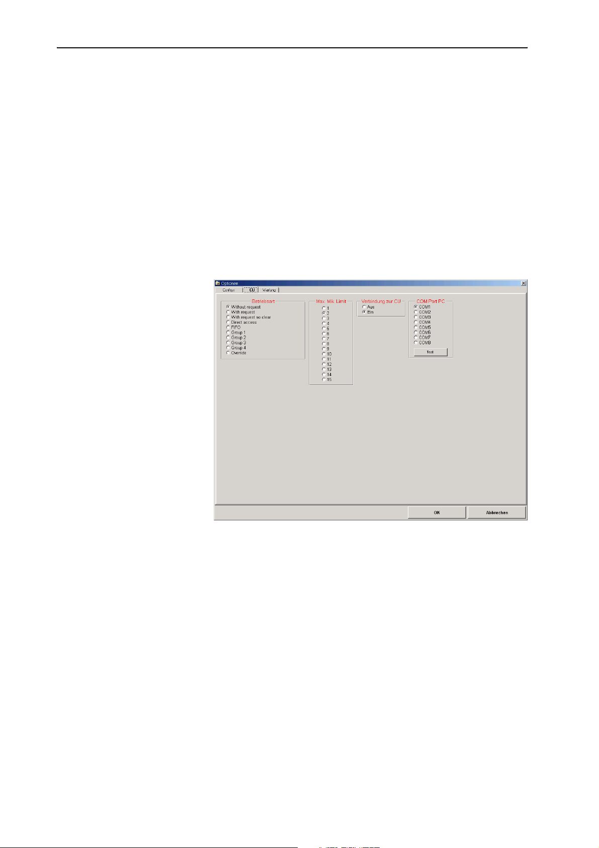
Configuring the conference system
Speech Timer y Automatic limiting of the speaking time (see “Configuring the speaker
limit” on page 49)
Program
TCP/IP address
Autostart y Autostart configuration and file paths of the synopic view and the
Path voting
Path copy
Path data
Sound y File paths of the sound files (see “Configuring acoustic signals” on
y Configuration of the network PCs as master, slave or video PC (see
“Configuring the PC in a network” on page 44)
delegate database (see “Configuring the startup options” on page 43)
y File paths of the log and safety files (see “Configuring the log files” on
page 47)
page 45)
The “CU” tab
Mode y Configuration of the conference mode (see “Configuring the conference
mode” on page 48)
Max. Micro ON y Max. number of simultaneously active consoles (see “Configuring the
speaker limit” on page 49)
Connection to CU y Connection to the central unit (on or off)
COM Port PC y Configuration and test of the connection between the central unit and
the PC (see “Configuring the COM port” on page 49)
41
Page 42
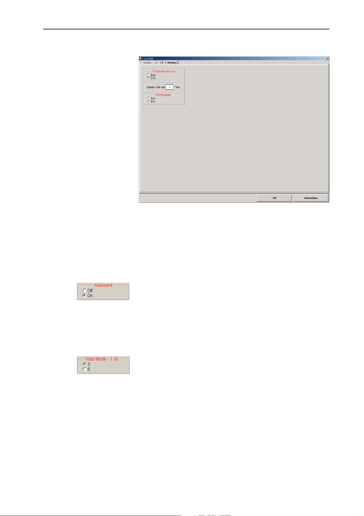
Configuring the conference system
The “Maintenance“ tab
Cleanup log file y Deletion of the log databases (see “Deleting log databases” on page 48)
Configuring the saving options
To set the program behaviour on exit:
왘 In the “Autosave” box on the “Confsys” tab, click the desired option
button.
y If you click the “Off” option button, a dialog box asks you to save your
changes before you exit the program. You can either save or not save
the changes.
y If you click the “On” option button, your changes are saved
automatically when you exit the program.
Configuring the voting settings
To preset the voting mode:
왘 In the “Vote mode – 1 of...” box on the “Confsys” tab, click the desired
option button.
y If you click the “3” option button, voting automatically starts in “1 of
3” mode.
y If you click the “5” option button, voting automatically starts in “1 of
5” mode (only if the SDC 8200 SYS software is being used).
42
Note:
You can change the selected voting mode at any time (see “Selecting
the voting mode” on page 84).
Page 43

Configuring the conference system
To allow/prevent changing the vote cast:
왘 In the “Vote Correction” box on the “Confsys” tab, click the desired
option button.
y If you click the “OFF” option button, a delegate cannot change the
vote cast.
y If you click the “ON” option button, a delegate can change the vote
cast until the voting time is over.
To configure the printouts of voting results:
왘 In the “Presences” box on the “Confsys” tab, click the desired option
button.
y If you click the “Name” option button:
In the printout, the voting results are assigned to the names in the
delegate database. For this the S-DM software module is required.
y If you click the “Micros” option button:
In the printout, the voting results are assigned to the microphone
numbers.
To add a heading to the printouts and log files of the voting results, the
delegate list and the agenda:
왘 In the “Votetext” box on the “Confsys” tab, click the desired option
button.
We recommend entering the title of your conference. Via this title, it
will later be possible to clearly assign all printouts to a certain
conference.
To add up to two logos to the voting window:
왘 In the “Logo1” or “Logo2” box on the “Confsys” tab, specify the file
path and the *.bmp file of the logos.
The logos then appear one above the another on the top right of the
voting window (see “Loading the agenda file” on page 81).
Configuring the startup options
To set the program behaviour on startup:
왘 In the “Autostart” box on the “Confsys” tab, click the desired option
button and specify the desired files under “Room file” and “Delegate
file”.
y If you click the “OFF” option button, no configuration is loaded when
the program is started and the empty “SDC 8200” window appears.
This setting is recommended for conference systems with a
frequently changing configuration and changing delegates.
y If you click the “ON” option button, the synoptic view of the
conference room preset under “Room file” and the delegate data
selected under “Delegate file” are loaded automatically.
43
Page 44
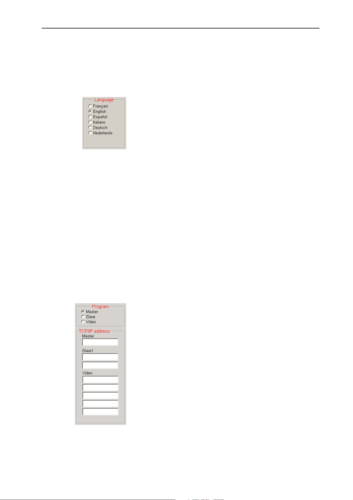
Configuring the conference system
This setting is recommended for conference systems with an
unchanging configuration.
Configuring the menu language of the software
To display the menus and buttons of the software in a different language
immediately after program startup:
왘 In the “Language” box on the “Confsys” tab, click the desired option
button.
Note:
You can change the menu language at any time (see “Changing the
menu language of the “Confsys” program” on page 21).
Configuring the PC in a network
If you have installed the software in parallel on several PCs, it is necessary
to specify the tasks of the PCs in the network:
y Master:
Control of the conference system and/or control of the interpretation
system, access control (dongle)
y Slave:
Control of the conference system and/or control of the interpretation
system
y Video:
Display of the synoptic view of the conference room, the delegate names
and the voting results (e.g. via a projector)
Note:
Your network administrator will give you the required TCP/IP addresses
of your PCs.
If the PC is to be configured as the master PC:
왘 In the “Program” box on the “Confsys” tab, click the “Master” option
button.
왘 Enter the TCP/IP addresses of the corresponding PCs in the “Master”,
“Slave1” and “Video” boxes of the “TCP/IP address” box.
This PC is now configured as the master PC.
44
Page 45
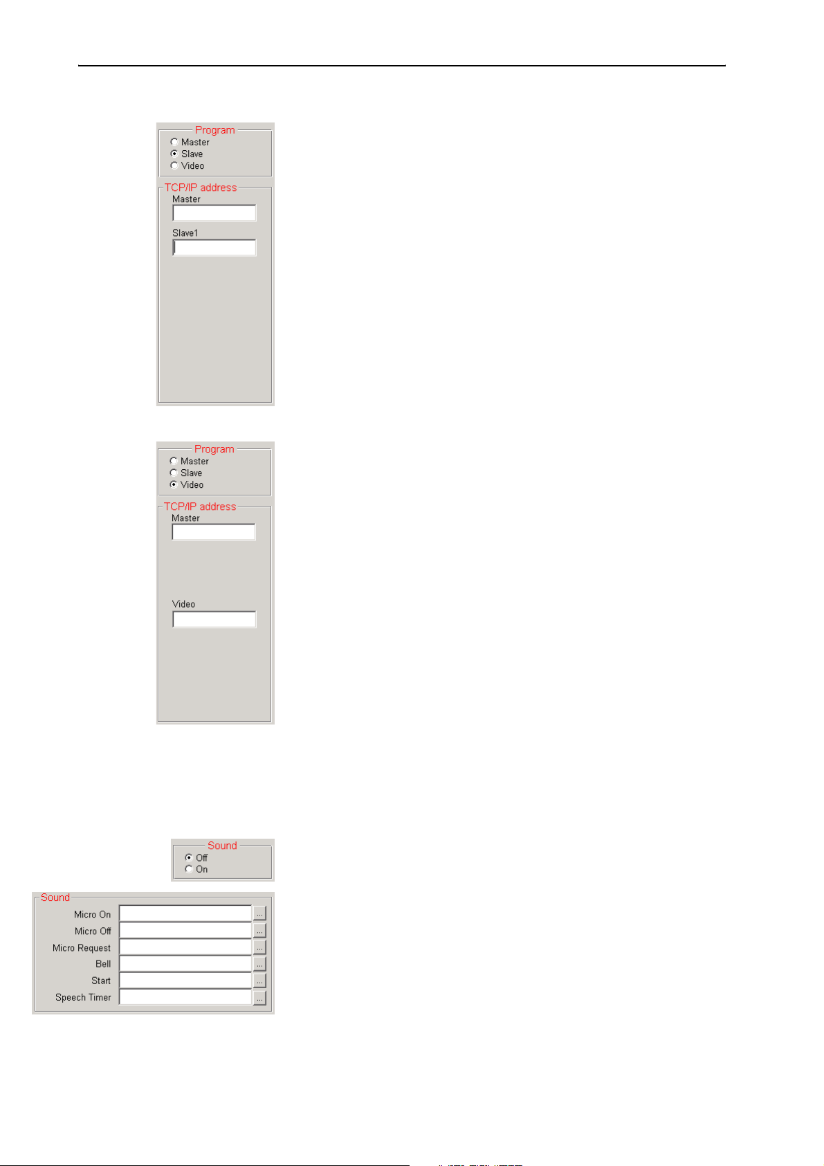
Configuring the conference system
If the PC is to be configured as a slave PC:
왘 In the “Program” box on the “Confsys” tab, click the “Slave” option
button.
왘 Enter the TCP/IP address of the master PC in the “Master” box of the
“TCP/IP address” box.
왘 Enter the TCP/IP address of the first slave PC in the “Slave1” box of the
“TCP/IP address” box.
This PC is now configured as a slave PC.
If the PC is to be configured as a video PC:
왘 In the “Program” box on the “Confsys” tab, click the “Video” option
button.
왘 Enter the TCP/IP address of the master PC in the “Master” box of the
“TCP/IP address” box.
왘 Enter the TCP/IP address of the video PC in the “Video” box of the “TCP/
IP address” box.
This PC is now configured as a video PC.
To prevent the video PC, at which no-one is working because it is used for
display purposes only, from starting the screensaver:
왘 Make sure that the screensaver of the video PC is deactivated.
Configuring acoustic signals
You can couple different system events with an acoustic signal. The
acoustic signal is output via the sound card of the master PC (not via the
conference consoles’ built-in loudspeakers).
왘 In the “Sound” box on the “Confsys” tab, click the “On” option button.
왘 Specify *.wav files for the different system events.
y If you enter a *.wav file in the “Micro On” box, it will be played each
time a microphone is activated.
y If you enter a *.wav file in the “Micro Off” box, it will be played each
time a microphone is deactivated.
y If you enter a *.wav file in the “Micro Request” box, it will be played
each time a delegate makes a request to speak.
45
Page 46
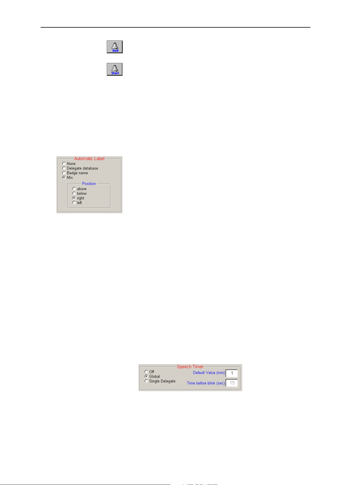
Configuring the conference system
y If you enter a *.wav file in the “Bell” box, it will be played each time
you click the “Bell” button (see “Triggering acoustic signals” on
page 80).
y If you enter a *.wav file in the “Start” box, it will be played each time
you click the “Start” button (if you enter a *.wav file in the “Speech
Timer” box, it will be played each time the preset max. speaking time
is reached (see “Using the “Global” option button in the “Speech
Timer” box” on page 69).
Note:
Some suitable *.wav files can be found in the folder “C:\Programs\
SDC8200\S_CM”.
Labelling conference console icons automatically
To configure the automatic labelling of the conference console icons:
왘 In the “Automatic Label” box on the “Confsys” tab, click the desired
option button.
y If you click the “None” option button, no icon label is automatically
added to the conference console icon.
y If you click the “Delegate database” option button, an icon label with
the name of the delegate is automatically added to the conference
console icon.
y If you click the “Badge name” option button, an icon label with the
name read from the chip card is automatically added to the
conference console icon (only if the SDC 8200 SYS software is being
used). If no chip card is inserted, no name will be displayed.
y If you click the “Mix” option button, an icon label with the name read
from the chip card is automatically added to the conference console
icon. If no chip card is inserted, the name from the delegate database
will be displayed.
왘 Choose the position where the icon label is to be added:
y above: the icon label is added above the console icon
y below: the icon label is added below the console icon
y right: the icon label is added at the right of the console icon
y left: the icon label is added at the left of the console icon
Configuring the maximum speaking time
To configure the maximum speaking time:
왘 In the “Speech Timer” box on the “Confsys” tab, click the desired option
button.
y If you click the “Off” option button, all delegates can speak for an
unlimited time.
y If you click the “Global” option button, you can start the speaking
time countdown at any time (see “The displays on the control palette” on page 67). After the maximum speaking time has been
reached, all microphones are deactivated automatically.
46
Page 47
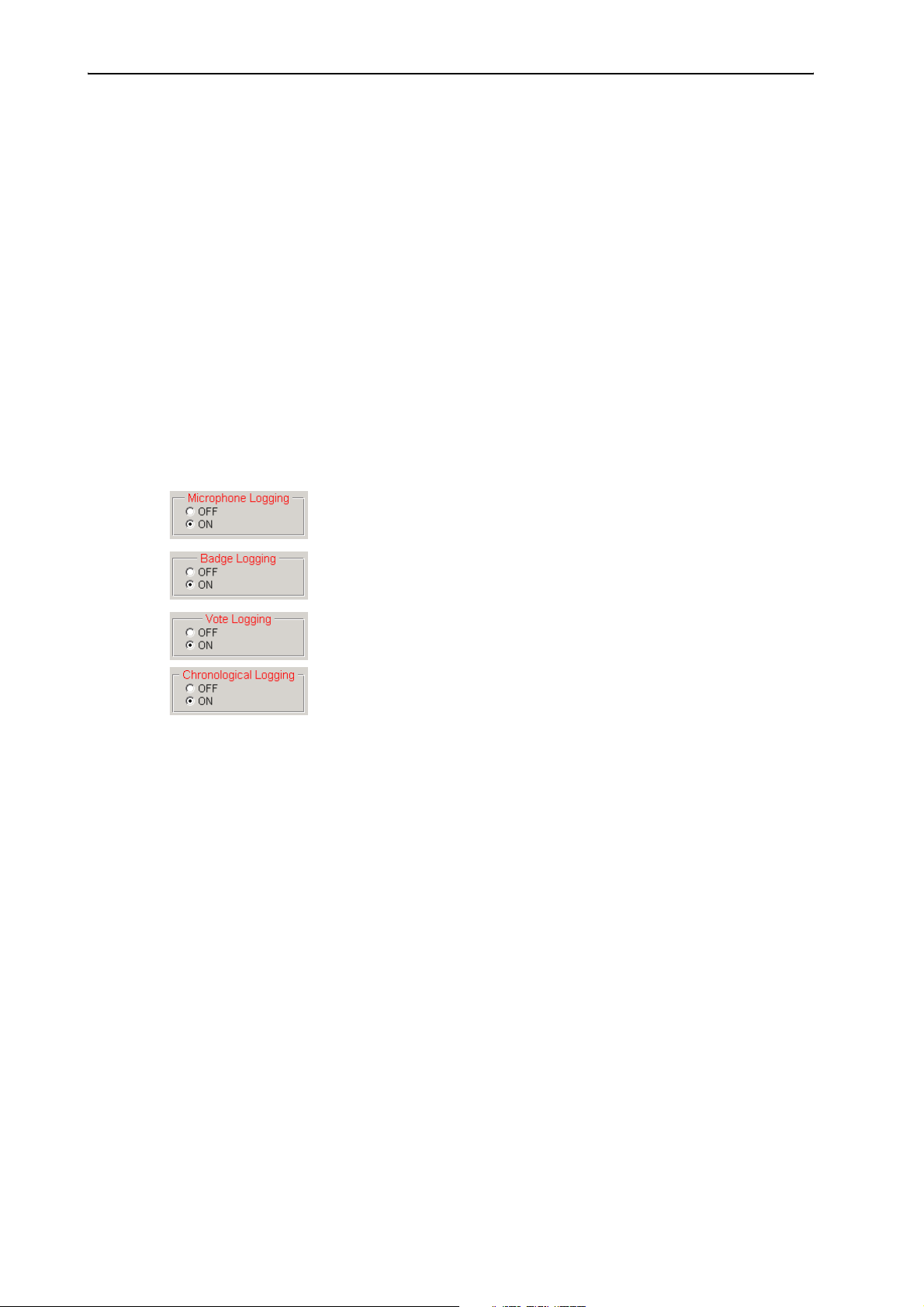
Configuring the conference system
y If you click the “Single Delegate” option button, an individual
speaking time countdown is started for each speaker. After the
maximum speaking time has been reached, the speaker’s microphone is deactivated automatically. You can interrupt or cancel the
countdown at any time (see “Using the “Global” option button in the
“Speech Timer” box” on page 69). The red signal light ring starts
flashing before the maximum speaking time is reached. The “Global”
option can be used in parallel.
왘 In the “Default Value (min)” field, enter the maximum speaking time in
minutes.
The maximum speaking time can be set from 1 to 200 minutes.
왘 In the “Time before blink (sec)” field, enter the duration of the flashing
of the red signal light ring in seconds.
A flashing red signal light ring indicates that the speaking time will
soon be over.
Configuring the log files
To configure the log files for different system events:
y “Microphone Logging”
Whenever a console is activated/deactivated, the microphone number,
the data of the delegate and the date and time are saved in a log file.
y “Badge logging”
Whenever a chip card is inserted into or removed from the chip card slot
of a console, this is saved in a log file.
y “Vote Logging”
All voting items are saved in individual log files.
y “Chronological Logging”
All system events are saved in a log file:
y Start/end of a conference + name of the conference,
y Activation/deactivation of a microphone + name of the delegate,
y Insertion/removal of a chip card + name of the delegate,
y Opening/closing the agenda + name of the delegate,
y Starting time/ending time of a voting item + description.
All log files of a conference are managed by a database. After the
conference, these databases are automatically saved in a folder to be
specified in the “Path data” box (see “Selecting the folders for saving the
voting results, safety copies and log files” on page 48). The format of the
name of a database is as follows:
LOG_year_month_day_hourminutesseconds.mdb
Example: LOG_2006_10_03_123031.mdb
After the conference, the log files can be printed or saved as described
under “Viewing, exporting and printing log files” on page 64.
To configure the log files:
왘 In one of the boxes “Microphone Logging”, “Badge Logging”, “Vote
Logging” and “Chronological Logging” on the “Confsys” tab, click the
desired option button.
y If you click the “On” option button, the desired log file is
automatically created after the conference. The log file is saved in the
database.
47
Page 48
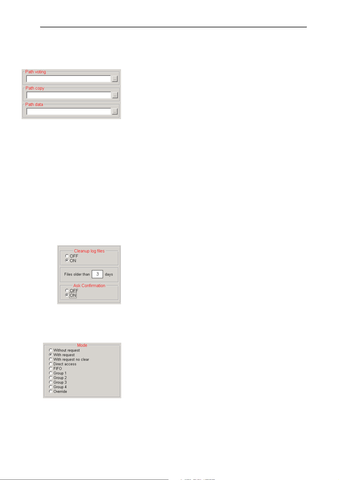
Configuring the conference system
Selecting the folders for saving the voting results, safety copies and log files
To select the folder for saving the different system files:
왘 In the boxes “Path voting”, “Path copy” and “Path data” on the
“Confsys” tab, select the folders in which the files are to be saved.
y Files with voting results are saved in a folder to be specified in the
“Path voting” box.
y All files are additionally saved in a folder to be specified in the “Path
copy” box.
y Log databases are saved in a folder to be specified in the “Path data”
box.
Note:
If you use several PCs (video, slave), it is absolutely necessary to ensure
y that the same folder is set on the same network drive of all PCs,
y that this folder is shared so that other PCs can access it (refer to the
Windows Help for full details on sharing folders) and
y that the PC with this network drive is turned on during the
conference!
We therefore urgently recommend selecting a folder on the master PC
for saving the log databases!
Deleting log databases
You can manually delete the log databases or set a deadline after which
the log databases are automatically deleted:
왘 In the “Cleanup log file” box on the “Maintenance” tab, click the “On”
option button.
왘 In the white field, enter the deadline (in days) after which the log
databases are to be automatically deleted.
왘 In the “Ask confirmation” box, choose whether or not the log databases
are to be deleted without asking for confirmation.
y Off: the log databases are deleted without asking for confirmation.
y On: the log databases are only deleted after your confirmation.
Configuring the conference mode
To preset a conference mode:
왘 In the “Mode” box on the “CU” tab, click the desired option button.
y For information on the ten different conference modes, see
“Operating the delegate units” on page 28 of the SDC 8200 system
manual.
y You can also change the conference mode at any time during a
conference (see “Changing the conference mode during a
conference” on page 78) – however, this causes all consoles to turn
off automatically.
48
Page 49
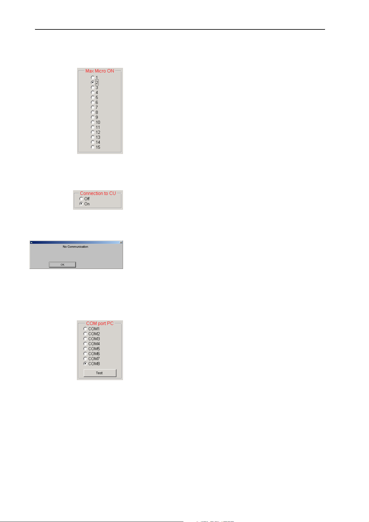
Configuring the conference system
Configuring the speaker limit
To limit the number of simultaneously active consoles:
왘 In the “Max Micro ON” box on the “CU” tab, click the desired option
button.
Note:
This only concerns the conference modes “Request”, “Direct Access”
and “Override”. In all other conference modes, the speaker limit is automatically set to the corresponding value.
Configuring communication with the central unit
To activate or deactivate communication with the central unit:
왘 In the “Connection to CU” box on the “CU” tab, click the desired option
button.
y If you click the “On” option button, the software tries to
communicate with the SDC 8200 CU central unit on startup. The “On”
option button must be active for the PC control of the conference
system to function correctly!
y If you click the “Off” option button, you cannot control your
conference system via the software!
If you wish to create a configuration even though no consoles are
connected, the “Off” option allows you to avoid the constant display
of the “No communication” dialog box.
Configuring the COM port
To configure the COM port of the PC for communication with the central
unit:
왘 Connect the central unit to the RS 232 interface of your PC as described
under “Connecting the PC to the central unit” on page 15.
왘 Turn on the central unit.
왘 Make sure that the “On” option button in the “Connection to CU” box
on the “CU” tab is clicked.
왘 In the “COM port PC” box on the “CU” tab, click the correct COM port.
This COM port must correspond to the serial RS 232 interface of the PC
to which the SDC 8200 central unit is connected.
If you click a COM port which is not available on your PC, a dialog box
with the message “COMx not available” appears (“x” corresponds to
the COM port number).
If you do not know the correct COM port, try the different options one after
the other:
왘 In the “COM port PC” box, first click a COM port and then click the “Test”
button.
y If a dialog box with the message “Test is successful on COMx”
appears, the PC can communicate with the central unit via the
49
Page 50

Configuring the conference system
selected COM port. Your conference system is now ready for
operation.
y If a dialog box with the message “Test failed on COMx” appears, you
have to try a different COM port.
Note:
Most desktop PCs have only one COM port (“COM1”) or two (“COM1”
and “COM2”). Only very rarely do PCs have more than two COM ports.
The COM ports of your PC are listed under “Ports (COM & LPT)” in the
Windows Device Manager.
However, in contrast to standard desktop PCs, on a number of laptops
the infrared interface (IrDa) and not the serial RS 232 interface is
preconfigured as “COM1”. In such a PC, the serial RS 232 interface
corresponds to “COM2”.
왘 Restart the program.
Saving the conference options
To save the selected options:
왘 Click the “Save and Exit” button.
The “Options” window closes and all selected options become active
when the program is restarted.
To reject the selected options and keep the previous options:
왘 Click the “Cancel and Exit” button.
The “Options” window closes and all previous options are kept.
50
Page 51

Managing delegate data
Managing delegate data
This chapter provides information on how to enter and use delegate data.
Entering delegate data
You can manually enter delegate data or import data from a file.
Note:
If you initialize the conference consoles after you created a delegate
database, the microphone numbers are fixedly assigned to the
delegate names. Therefore, the delegates always have to use the same
conference consoles in order to ensure that the correct name is
displayed in the list on the left-hand side of the “Delegates” window!
If you use chip cards, the microphone numbers are not fixedly assigned
to the delegate names. In this case, you do not have to enter any
delegate data. Instead, the delegate names stored on the chip cards are
automatically displayed in the delegate list (only if the SDC 8200 SYS
software is being used).
Creating or opening a delegate database
To create a delegate database:
왘 From the “Delegates” menu, choose “Administration” or click the
“Delegates” button in the “SDC 8200” window.
The “Delegates” window opens.
The buttons for chip card management at the bottom part of the
“Delegates” window are not available in the SDC 8200 SYS-M software.
To create a new delegate database:
왘 From the “File” menu, choose “New”.
A new empty input mask is created.
51
Page 52

Managing delegate data
To open an existing delegate database:
왘 From the “File” menu, choose “Open”.
The file selection box opens.
왘 Specify the folder and name of the delegate list to be opened and click
the “OK” button.
All delgate names entered up to now are displayed in the list on the
left-hand side of the window. The buttons on the right-hand side of the
window become active.
The delgate names in the list are sorted by microphones numbers. The
middle part of the window contains the input mask and the buttons on
the right-hand side are for editing the data records.
Adding new delegate data
To add new delegate data to the dalegate database:
왘 In the “Delegates” window, click the “Add” button.
The insertion point appears in the “Micro” field.
왘 Enter the data into the different fields one after the other. Please note:
The microphone number (“Micro” box) and the name (“Name” box)
must be entered.
왘 Click the “Save” button.
The new data are added to the delegate database and the microphone
number, the last name and the first name of the delegate are displayed
in the list.
Changing delegate data
To change delegate data:
왘 In the list of the “Delegates” window, click the name of the delegate
whose data you want to change.
The data are displayed in the input mask.
52
왘 Click the “Change” button.
왘 Change the data.
왘 Click the “Save” button.
The changed data record replaces the previous record in the database.
Page 53

Managing delegate data
Deleting data from the delegate database
To delete data from the delegate database:
왘 In list of the “Delegates” window, click the name of the delegate whose
data you want to delete.
The data are displayed in the input mask.
왘 Click the “Delete” button.
The “Delete Record” dialog box opens.
왘 In the dialog box, click the “OK” button.
The data record is deleted from the database.
Searching for data in the delegate database
To search for specific data in the delegate database:
왘 In the “Delegates” window, click the “Search” button.
The “Micro”, “Delegate ID”, “Name”, “District”, “Birthdate” and “Party”
boxes turn red.
왘 Click a red box, enter the search term and press the “Enter” key.
If the entered search term is found, the corresponding delegate name
is highlighted in the delegate list and the data are displayed in the
input mask.
To scroll through the delegate database:
왘 In the “Delegates” window, click one of the arrow buttons.
The previous or the next entry of the corresponding box is displayed in
the input mask and the corresponding delegate name is highlighted in
the list.
Note:
If the arrow buttons are not active, click any button on the right-hand
side of the window and then interrupt the starting process by clicking
the “Cancel” button.
Moving data within the delegate database
To move delegate data to a new microphone number:
왘 In delegate list of the “Delegates” window, click the name of the
delegate whose data you want to move.
The data are displayed in the input mask.
왘 Click the “Move” button.
A green field appears next to the “Micro” box.
왘 Enter the desired microphone number – which must not yet be
assigned! – into the green field and press the “Enter” key.
The data of the selected delegate is moved to the new microphone
number. The entry in the delegate list is moved correspondingly.
53
Page 54

Managing delegate data
Importing delegate data
Instead of manually entering delegate data, you can import them from a
text file. The text file must have the extension .txt. All delegate records
must be separated by carriage returns and all fields within each record
must be separated by semicolons.
The order of the data in the text file:
Data Field Max. number of characters
y Microphone number (Micro) 4
y ID (ID) 13
y Chip card number (Badge Number) 4
y Last name (Name) 40
y First name (First name) 20
y Street: (Street) 30
y ZIP code (ZIP code) 4
y City (City) 20
y Organization (Party) 15
y District (District) 30
Example: “Delegates.txt“
0001; Luthi; Maria; Rämistr. 10; 8092; Zürich; CH; Switzerland
0002; Becker; Martin; Goethestr. 12; 1026; Vienna; A; Austria
0003; Richter; Andreas;Hofplatz 7; 1001; Vaduz; FL; Liechtenstein
To import delegate data:
왘 From the “Delegates” menu, choose “Import Delegates”.
The “Import Delegates” window opens.
54
왘 Click the “Select import file” button, select a *.txt file and confirm
your selection by clicking the “OK” button.
The path and the file name are displayed in the field below “Import file
name”.
Page 55

Managing delegate data
왘 Click the “Select destination file” button, specify the folder and name
of the new delegate database to be created and confirm your selection
by clicking the “OK” button.
The path and the file name are displayed in the field below “Destination
file name”.
왘 Click the “Start import” button.
The delegate data are displayed in the lower part of the window and
the “Clear” button appears. A delegate database containing the
delegate records of the text file is automatically created and saved.
To import more delegate data:
왘 Click the “Clear” button.
The fields are cleared and additional delegate data can be imported.
Printing a delegate list
You can print lists containing the microphone number, last name, first
name and organization of each delegate. These lists can be sorted by
microphone number, last name or by organization.
To print a delegate list:
왘 From the “Delegates” menu, choose either “Print sorted by
microphone”, “Print sorted by name” or “Print sorted by party”.
The file selection box opens.
왘 Select the delegate list to be printed and confirm your selection by
clicking the “OK” button.
The “Start Printing?” dialog box opens.
왘 Click the “OK” button.
The selected delegate list is printed.
Note:
To automatically add a heading to the printout, see “Configuring the
voting settings” on page 42.
Using chip cards
Chip cards allow you to give your conference a more personal and flexible
touch while making it more convenient. And it makes voting safer. In order
to be able to use the functionality of the chip cards, you require the
SDC 8200 SYS software:
y You do not need to enter any data into the delegate list. Instead, the
delegate list is updated automatically with the names stored on the chip
card as soon as a delegate inserts his chip card into the chip card slot of
his console.
The delegates can thus sit down at any desired console or swap places
with someone else whenever they want and the correct name is still
displayed next to the current microphone number. Absent delegates do
not appear on the delegate list.
If you have entered names into the delegate list nevertheless, these are
overwritten by the names on the chip cards as soon as a chip card is
55
Page 56

Managing delegate data
inserted into the chip card slot of a console. If the chip card is removed
again, a name is no longer assigned to this console
y If a delegate inserts his chip card into the chip card slot of any desired
console, his last name appears on the display of the console instead of
the microphone number.
y You can ensure that only authorized delegates participate in voting
sessions (see “Taking votes with or without chip cards” on page 83).
y You can – e.g. as a presence check – record which delegates have
inserted their chip card into the chip card slot of their console (see
“Saving or printing the data of all inserted chip cards” on page 78).
y You can use printed chip cards (e.g. bearing the logo of your conference
or conference center) and thus give your conference a personal,
individual touch.
For this, you require the S-MM, S-DM and S-VM software modules as well
as consoles with a chip card slot (SDC 8200 CV or SDC 8200 DV).
Writing data to chip cards
In order to write personal data of the delegates to chip cards, you require
the SDC 8200 SYS software.
왘 From the “Delegates” menu, choose “Administration” or click the
“Delegates” button in the “SDC 8200” window.
The “Delegates” window opens.
The buttons for chip card management at the bottom part of the
“Delegates” window are not available in the SDC 8200 SYS-M software.
왘 Insert a chip card into the slot of each of the consoles. The chip must
point downwards and to the left.
The green LED on the chip card icon of the corresponding consoles
lights up. The consoles with a chip card inserted into their chip card slot
are displayed in white in the synoptic view.
56
왘 Make sure that all consoles with inserted chip cards are displayed in
white in the synoptic view.
Page 57

Managing delegate data
왘 Click the “Write all” button.
The delegate data from the delegate list are written the the chip cards.
This takes several seconds. The delegate’s last name then appears on
the display of the console – provided that the console has a display.
To write data to a single chip card:
왘 Open a delegate list.
왘 Select the desired delegate.
왘 Insert a chip card into the slot of the delegate’s conference console.
왘 Click the “Write” button.
The data of the selected delegate are writen to the chip card.
Reading chip cards
To read the personal data of the delegates on the chip cards, you require
the SDC 8200 SYS software.
왘 Insert a chip card into the chip card slot of each conference console. The
chip must point downwards and to the left.
The green LED on the chip card icon of the conference consoles lights up
and the consoles are displayed in white in the synoptic view.
왘 Click the “Read All” button.
The data on all chip cards are read.
Reading a single chip card
To read the personal data of a delegate on a single chip card, you require
the SDC 8200 SYS software.
왘 In the field next to the “Read” button, enter the four-digit microphone
number of the conference console whose inserted chip card you want
to read.
The data on the chip card are read into the delegate database.
57
Page 58

Planning and managing votes (Agenda)
Planning and managing votes (Agenda)
In order to be a ble to quick ly and easil y take votes durin g a con feren ce, yo u
should create an agenda including all items to be voted on.
Entering voting data
Creating or opening an agenda file
왘 From the “Agenda” menu, choose “Administration” or click the
“Agenda” button in the “SDC 8200” window.
왘 The “Agenda Items” window opens.
The upper part of the window contains the input mask, the lower part
displays the agenda and the buttons on the right-hand side of the
window are for editing the agenda.
To create an agenda file:
왘 From the “File” menu, choose “New”.
A new empty input mask is created.
To open an existing agenda file:
왘 From the “File” menu, choose “Open”.
The file selection box opens.
왘 Specify the folder and name of the agenda file to be opened and click
the “OK” button.
58
Page 59

Planning and managing votes (Agenda)
All voting items entered up to now are displayed in the agenda. The
buttons on the right-hand side of the window become active.
Adding new voting items to the agenda file
To add a voting item to the agenda file:
왘 In the “Agenda Items” window, click the “Add” button.
The insertion point appears in the “Item” field.
왘 Enter the data into the different fields one after the other.
왘 Click the “Save” button.
The new voting item is added to the agenda file and is displayed in the
agenda.
Changing voting items in the agenda file
To change a voting item in the agenda file:
왘 In the agenda of the “Agenda Items” window, click the voting item you
want to change.
The data are displayed in the input mask.
3 왘 Click the “Change” button.
왘 Change the data.
왘 Click the “Save” button.
The changed voting item replaces the previous one in the agenda file.
Changing the quorum in the agenda file
“Quorum” is the minimum number (in percent) of delegates necessary to
be present for a vote.
To change the quorum for a single voting item:
왘 In the “Agenda Items” window, click the voting item which is to be
assigned a different quorum.
왘 In the “Quorum” field, enter the desired percent value.
59
Page 60
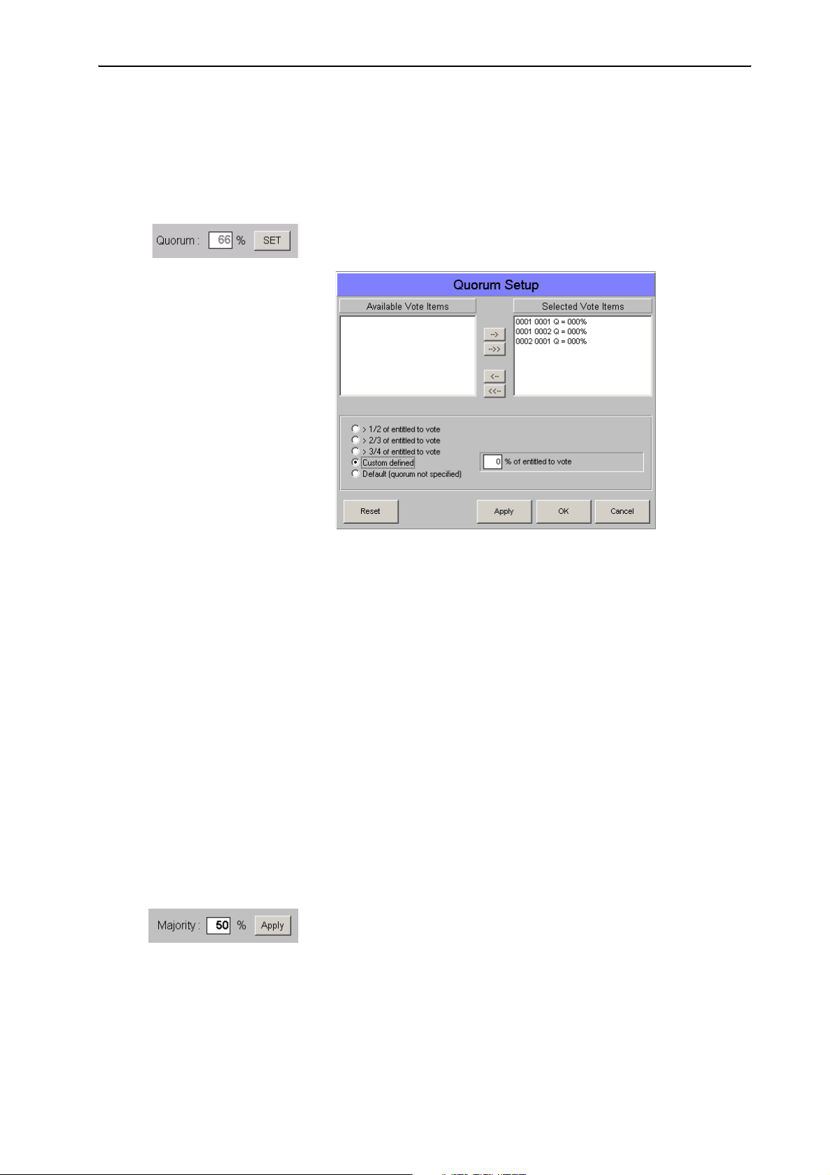
Planning and managing votes (Agenda)
왘 Click the “OK” button.
The changed quorum is saved in the database as soon as you save the
database file or close the “Agenda Items” window.
To change the quorum for several voting items at the same time:
왘 In the “Agenda Items” window, use Ctrl-click or Shift-click to select all
voting items which are to be assigned a different quorum.
왘 Click the “SET” button next to the “Quorum” field.
The “Quorum Setup” window opens.
The selected voting items are listed in the “Selected Vote Items” field.
You can click individual voting items and move them from one field to
the other by using the “arrow” buttons.
왘 Click the option button next to the desired quorum.
If you click “Custom defined”, a box opens where you can enter any
number from 0 to 100.
왘 Click the “Apply” button.
The selected quorum is assigned to all voting items listed in the
“Selected Vote Items” field. All voting items are moved back to the
“Available Vote Items” field.
왘 Click the “OK” button.
Changing the majority ratio in the agenda file
“Majority” is the minimum number (in percent) of delegates necessary to
vote in favour of a voting item in order for that voting item to be passed.
To change the majority ratio for a single voting item:
왘 In the “Agenda Items” window, click the voting item which is to be
assigned a different majority ratio.
왘 In the “Majority” field, enter the desired percent value.
왘 Click the “OK” button.
The changed quorum is saved in the database as soon as you save the
database file or close the “Agenda Items” window.
60
To change the majority ratio for several voting items at the same time:
왘 In the “Agenda Items” window, use Ctrl-click or Shift-click to select all
voting items which are to be assigned a different majority ratio.
Page 61
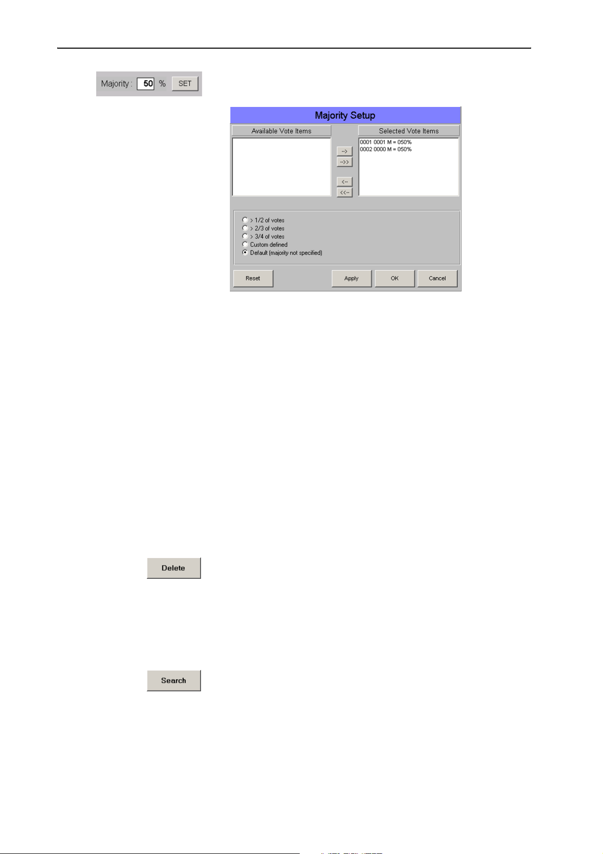
Planning and managing votes (Agenda)
왘 Click the “SET” button next to the “Majority” field.
The “Majority Setup” window opens.
The selected voting items are listed in the “Selected Vote Items” field.
You can click individual voting items and move them from one field to
the other by using the “arrow” buttons.
왘 Click the option button next to the desired majority ratio.
If you click “Custom defined”, a box opens where you can enter any
number from 0 to 100.
왘 Click the “Apply” button.
The selected majority ratio is assigned to all voting items listed in the
“Selected Vote Items” field. All voting items are moved back to the
“Available Vote Items” field.
왘 Click the “OK” button.
Deleting voting items from the agenda file
To delete a voting item from the agenda file:
왘 In the agenda of the “Agenda Items” window, click the name of the
voting item you want to delete.
The data are displayed in the input mask.
왘 Click the “Delete” button.
The “Delete Record?” dialog box opens.
왘 In the dialog box, click the “OK” button.
The voting item is deleted from the agenda file.
Searching for voting items in the agenda file
To search for a voting item in the agenda file:
왘 In the “Agenda Items” window, click the “Search” button.
The “Item” box turns red.
왘 Click the red “Item” box, enter the number of the searched voting item
and press the “Enter” key.
If the number is found, the corresponding voting item is highlighted in
the agenda and its data are displayed in the input mask.
61
Page 62

Planning and managing votes (Agenda)
To scroll through the agenda file:
왘 In the “Agenda Items” window, click one of the arrow buttons behind
the “Item” box.
The previous or the next entry is displayed in the input mask and the
corresponding voting item is highlighted in the agenda.
Moving voting items within the agenda file
To move a voting item to a new item number:
왘 In agenda of the “Agenda Items” window, click the voting item you
want to move.
The data are displayed in the input mask.
왘 Click the “Move” button.
A green field appears next to the “Item” box.
왘 Enter the desired item number – which must not yet be assigned! – into
the green field and press the “Enter” key.
The selected voting item is moved to the new item number in the
agenda file. The entry in the agenda is moved correspondingly.
Importing voting items
Instead of manually entering voting items, you can import them from a
text file. The text file must have the extension .txt. All voting items must
be separated by carriage returns and all fields must be separated by
semicolons.
The order of the data in the text file:
Data Field Max. number of characters
y Number of voting item (Item) 3
y Number of amendment (Amendment) 2
y Description (Description) 30
y Voting option (Index 1) 3
y Voting option 2 (Index 2) 3
y Voting option 3 (Index 3) 3
y Quorum (Quorum) 3
y Majority (Majority) 3
Example: “Agenda.txt“
001; 01; Election of the chairman; Arc; Bec; Mil 50; 66;
001; 02; Election of the vice chairman; Arc; Bec; Mil 50; 50;
003; 00; Finances; Op1; Op2; Op3 100; 50;
62
To import voting items:
왘 From the “Agenda” menu, choose “Import Agenda”.
Page 63

Planning and managing votes (Agenda)
The “Import Agenda” window opens.
왘 Click the “Select import file” button, select a *.txt file and confirm
your selection by clicking the “OK” button.
The path and the file name are displayed in the field below “Import file
name”.
왘 Click the “Select destination file” button, specify the folder and name
of the new agenda file to be created and confirm your selection by
clicking the “OK” button.
The path and the file name are displayed in the field below “Destination
file name”.
왘 Click the “Start import” button.
The voting items are displayed in the lower part of the window. An
agenda file containing the data of the text file is automatically created
and saved.
Printing an agenda file
To print an agenda file:
왘 From the “Agenda” menu, choose “Print”.
The file selection box opens.
왘 Select the agenda file to be printed and confirm your selection by
clicking the “OK” button.
The “Start Printing?” dialog box opens.
왘 Click the “OK” button.
The selected agenda file is printed.
Note:
To automatically add a heading to the printout, see “Configuring the
voting settings” on page 42.
63
Page 64
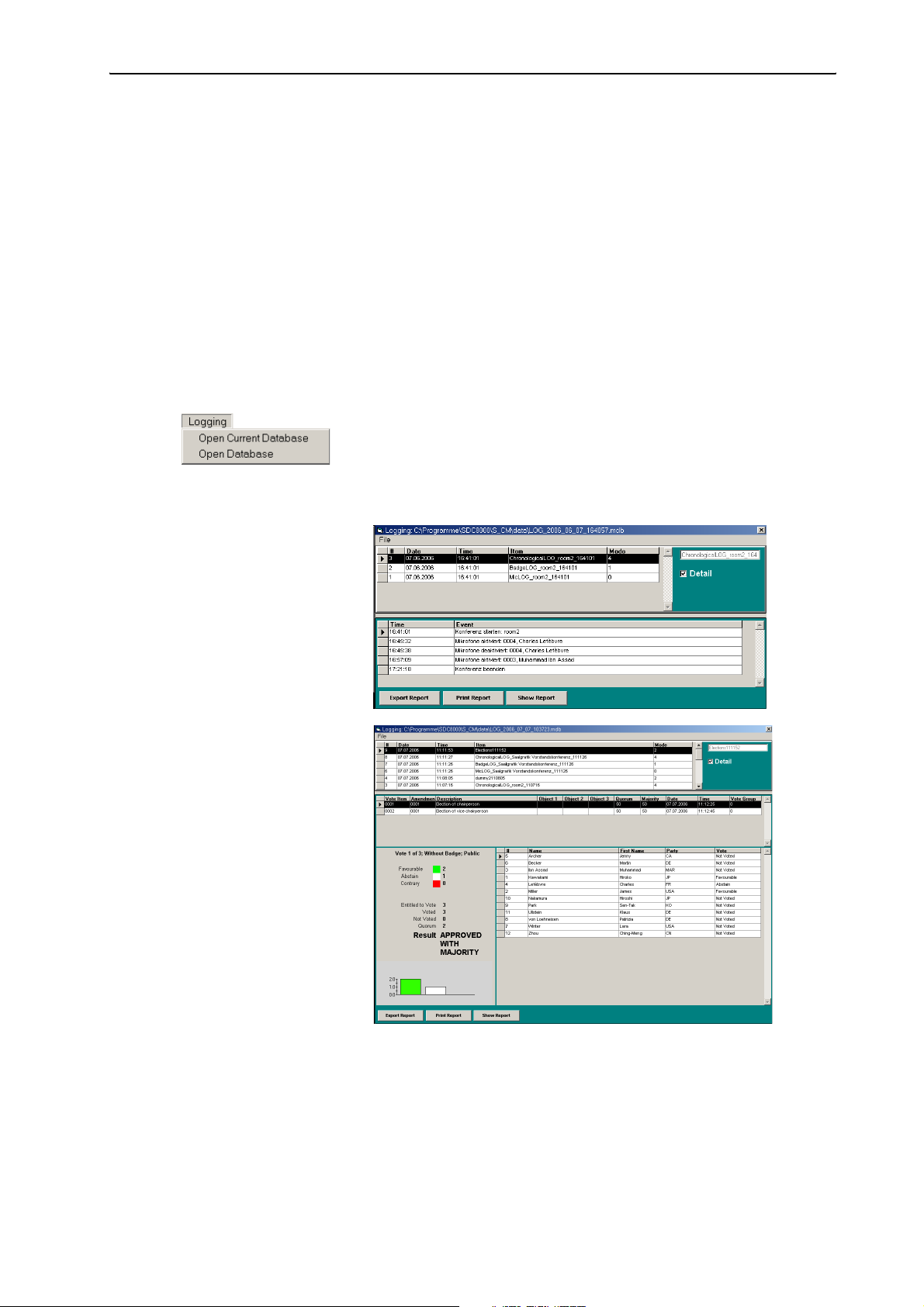
Planning and managing votes (Agenda)
Viewing, exporting and printing log files
You can create log files for different system events during a conference
(see “Configuring the log files” on page 47).
All log files are saved in a Microsoft Access database (file extension
*.mdb). For each conference, the software automatically creates an mdb
file which is saved in a folder to be specified in the “Path data” box (see
“Selecting the folders for saving the voting results, safety copies and log
files” on page 48). The format of the name of a database is as follows:
LOG_year_month_day_hourminutesseconds.mdb
Example: LOG_2006_10_03_123031.mdb
To export or print the log files of a database:
To open the database of the current conference:
왘 From the “Logging” menu, choose “Open Current Database”.
To open a different database:
왘 Click “Open Database” and then select the desired database.
The database opens.
Log database with
chronological log file
Log database with
vote log file
왘
64
The upper table displays all log files created during the conference. (For
how to specify the log files to be created during a conference, see
“Configuring the log files” on page 47.)
The lower table displays all events recorded in the selected log file. In
the case of a vote log file, the voting result is also displayed. You can
display or hide these events by clicking or unclicking the “Details”
check box.
Page 65

Planning and managing votes (Agenda)
왘 In the upper table, click the desired log file.
To view a log file:
왘 Click the “Show Report” button.
The log file is displayed. You can scroll through the log file using the
buttons on the menu bar, and you can scale and print the log file.
To print a log file:
왘 Click the “Print Report” button.
The printer driver window opens. Print the file as usual.
To export a log file:
왘 Click the “Export Report” button.
The “Export Report” window opens.
왘 In the white field, enter the name to be assigned to the files to be
exported.
왘 In the “Format” box, click the check boxes of the file formats to be
created.
You can export several formats at the same time.
왘 Click “OK”.
The log file is saved in a folder to be specified in the “Path data” box
(see “Selecting the folders for saving the voting results, safety copies
and log files” on page 48).
Note:
If you export log files in the HTML format, the software automatically
creates a folder named “X_Files” (where “X” corresponds to the file
name chosen by you). If you pass on the HTML files, you have to pass
on the “X_Files” folder too. Alternatively, the “X_Files” folder must be
available online.
65
Page 66
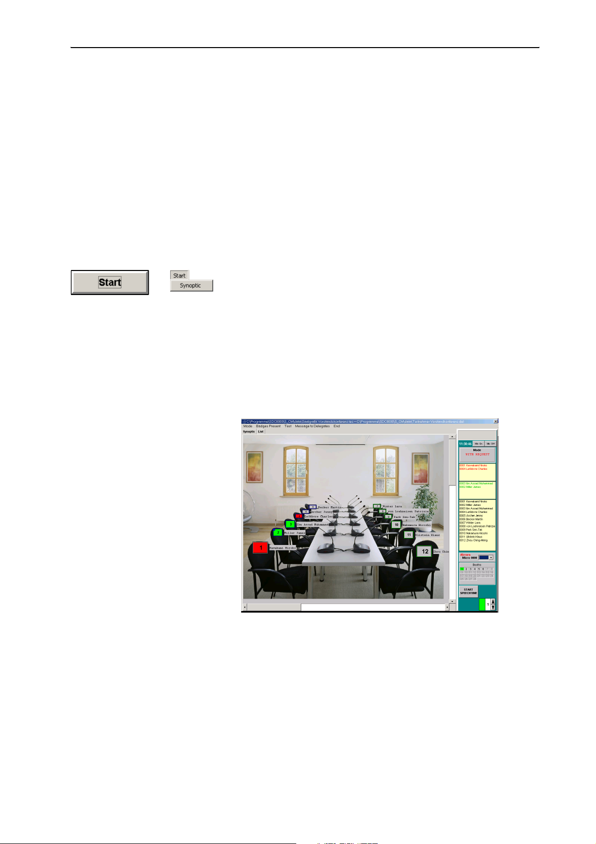
Monitoring and controlling a conference
Monitoring and controlling a conference
This chapter provides information on how to monitor a conference, how to
intervene in a conference and how to take votes.
Starting a conference
To start a conference:
왘 Make sure that all components are connected correctly and that the
central unit is turned on.
The configuration must be error-free (see “Configuring the conference
system” on page 22) and the conference consoles must be initialized
(see “Initializing the conference consoles” on page 37).
왘 From the “Start” menu, choose “Synoptic” or click the “Start” button.
The file selection box opens.
왘 First select the *.tec file containing the synoptic view of your
conference and confirm your selection by clicking the “OK” button.
A second file selection box opens.
왘 Select the *.del file containing the names of the delegates and
confirm your selection by clicking the “OK” button.
If you have not licensed the S-DM software module and thus have no
delegate data, click “Cancel”.
The synoptic view opens and the conference can start immediately.
The synoptic view shows the console icons.
66
Page 67
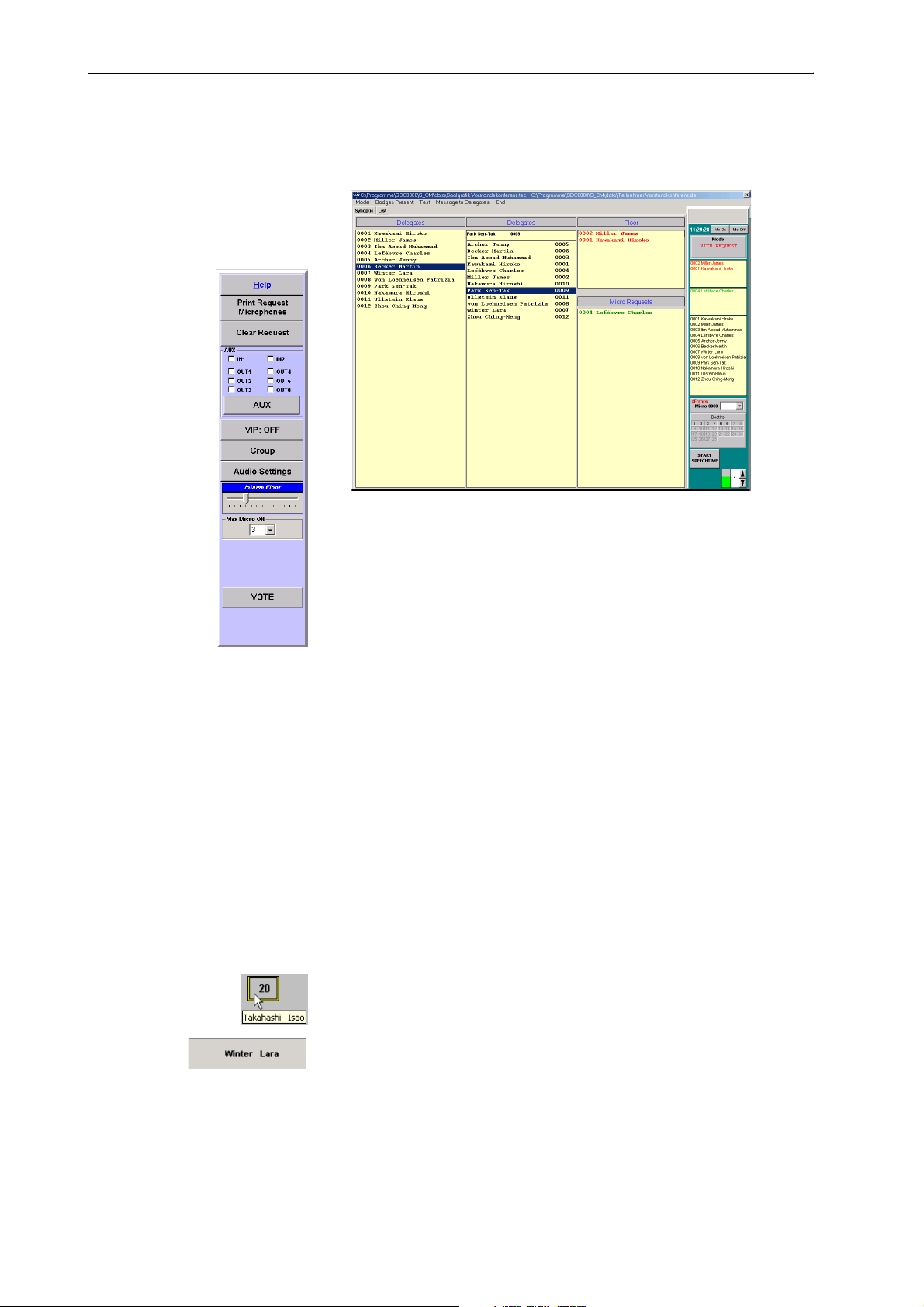
To change to the delegate list:
왘 Click the “List” tab.
The delegate list opens.
Monitoring and controlling a conference
The delegate list shows the names of the delegates.
The synoptic view and the delegate list display the control palette on the
right-hand margin of the screen.
If you move the mouse pointer to the left-hand margin of the screen in the
synoptic view or the delegate list, the tool palette shown on the left is
displayed.
Monitoring and controlling a conference via the control palette
When a delegate makes a request to speak or a request to speak is
granted, the name of the delegate is displayed in the corresponding boxes
of the control palette – provided you have licensed the S-DM software
module.
The displays on the control palette
To display the name of any desired delegate:
왘 In the synoptic view, position the mouse pointer on the console icon of
the delegate whose name you want to display.
The name of the delegate is temporarily displayed next to the console
icon.
The name of the delegate also appears running across the gray field at
the top of the control palette.
If you have clicked one of the option buttons “Delegate
database“,“Badge name” or “Mix” in the “Automatic Label” box on the
“Confsys” tab (see “Labelling conference console icons automatically”
on page 46), icon labels with the names of the delegates are displayed
next to the conference console icons – even if you do not position the
mouse pointer on the console icon.
67
Page 68

Monitoring and controlling a conference
The current time is displayed next to the “Mic On” and “Mic Off” buttons
on the control palette (see “Deactivating all consoles” on page 68 and
“Reactivating the last active console” on page 69).
The conference mode is displayed in the “Mode” box.
In order to view the names of the delegates as described in the following,
you require the S-DM software module.
y The names of all current speakers and their microphone numbers are
automatically displayed in red in the upper yellow box (“Active
Speakers” box).
y The names of all delegates who have made a request to speak and their
microphone numbers are automatically displayed in green in the lower
yellow box (“Requests” box).
y The names of all delegates and their microphone numbers are displayed
in black in the “All delegates” box.
y Inoperable (i.e. wrongly connected or defective) consoles are displayed
in the “#Errors” box. The microphone numbers of the inoperable
consoles are displayed in the drop down list box.
The inoperable consoles are also displayed in yellow in the synoptic view
(see “Monitoring the conference console icons in the synoptic view” on
page 70).
y The operating states of the interpreter booths are displayed in the
“Booths” box – even if you do not have a license for the S-IM software
module or it is currently not in operation.
Each interpreter booth is represented by a booth icon displaying the
booth number. The booth number corresponds to the channel number of
the main target language configured. If someone is interpreting via one
of the consoles in an interpreter booth, the booth icon is displayed in
green; if a console in a booth is not active, the booth icon is displayed in
gray.
y If you have specified a maximum speaking time for the “Global” option
in the “Speech Timer” box on the “Confsys” tab (see “Configuring the
maximum speaking time” on page 46), different displays and buttons
for limiting and monitoring the speaking time appear in the lower part
of the control palette (see “Using the “Global” option button in the
“Speech Timer” box” on page 69).
y If you have specified a maximum speaking time for the “Single
Delegate” option in the “Speech Timer” box on the “Confsys” tab (see
“Configuring the maximum speaking time” on page 46), a window
containing different displays and buttons for limiting and monitoring
the speaking time appears in the synoptic view (see “Using the “Single
Delegate” option button in the “Speech Timer” box” on page 69).
68
Deactivating all consoles
To deactivate all active consoles:
왘 Click the “Mic Off” button on the control palette.
All active consoles are deactivated. At the same time, all requests to
speak are cancelled.
Page 69

Monitoring and controlling a conference
Reactivating the last active console
This function is e.g. for the quick reactivation of the console of a delegate
whose speaking time is over.
To reactivate the last active console:
왘 Click the “Mic On” button on the control palette.
The last deactivated console is reactivated.
Using the “Single Delegate” option button in the “Speech Timer” box
The green bar shows the countdown of the speaking time. You can control
this speaking time as follows:
To temporarily interrupt the countdown:
왘 Click the “HOLD” button.
The speaker can continue to speak while the countdown is temporarily
interrupted.
To continue the countdown:
왘 Click the “Proceed” button.
To stop the countdown:
왘 Click the “STOP” button.
The countdown stops and the “speaking right” is withdrawn from the
speaker.
Using the “Global” option button in the “Speech Timer” box
To change the preset maximum speaking time:
왘 Click one of the arrows in the “Max. speaking time” box in the lower
part of the control palette.
You can set speaking times of between 1 and 200 minutes.
To start the countdown:
왘 Click the “START SPEECHTIME” button.
The countdown starts. The green bar shows the countdown of the
speaking time. The clock is displayed and shows the countdown in
seconds.
To temporarily interrupt the countdown:
왘 Click the “HOLD” button.
The countdown is interrupted.
To continue the countdown:
왘 Click the “CONTINUE” button.
The countdown continues.
To stop the countdown:
왘 Click the “STOP SPEECHTIME” button.
The countdown stops. The clock and the “Max. speaking time” box are
no longer displayed.
The system is now ready to start a new countdown.
69
Page 70

Monitoring and controlling a conference
Defective
Chairman
Chip card inserted
Request to speak made
Inactive
Request to speak granted
Monitoring the conference via the synoptic view
To work with the synoptic view:
왘 Click the “Synoptic” tab.
The synoptic view opens.
Monitoring the conference console icons in the synoptic view
The different colors of the conference console icons in the synoptic view
have the following meanings:
y The border color (here: blue) of a conference console icon is selected
when the synoptic view is created – e.g. in order to distinguish different
delegate groups.
y Yellow conference console (2):
The corresponding conference console is defective or not connected
correctly.
Pink conference console icon (3):
y
The corresponding conference console is configured as the chairman unit.
y White conference console icon (4):
A chip card is inserted into the chip card slot of the corresponding
conference console.
y Green conference console icon (5):
The delegate has made a request to speak by pressing the microphone
key 씊.
y Red conference console icon (6):
The delegate has been granted the request to speak.
y Gray conference console icon (7):
The conference console is currently inactive.
Monitoring conference operation via the delegate list
To work with the delegate list:
왘 Click the “List” tab.
The delegate list is displayed.
Monitoring the name boxes in the delegate list
You can also monitor the conference via the delegate list instead of the
synoptic view. The names are displayed in the following boxes:
y The left-hand “Delegates” box lists all delegate names in the order of
their microphone numbers. If you click this box and rapidly enter a fourdigit microphone number, the name of the delegate seated at the
console with this microphone number is highlighted.
y The right-hand “Delegates” box lists all delegate names in alphabetical
order. If you click this box and enter a letter, the first name in the list to
begin with this letter is highlighted.
70
Page 71

Monitoring and controlling a conference
y The names of all delegates who are currently speaking are listed in red
in the “Floor” box.
y In the “With request” and “With request no clear” conference modes,
the names of all delegates who have made a request to speak are listed
in green in the “Micro Requests” box.
Intervening in the conference
Activating a console
Once you have activated a console, the following happens:
y In the synoptic view, the icon of the deactivated console turns red.
y The name of the delegate at the activated console appears in the “Floor”
box of the delegate list.
y The name of the delegate at the activated console appears in the “Active
Speakers” box of the control palette.
y The signal light ring and the “Microphone active” LED of the activated
console light up. The delegate can speak immediately.
Depending on the conference mode, you can activate several consoles in
succession – until the speaker limit set in the options is reached.
To activate a console in the synoptic view:
왘 Click the gray console icon of the console you want to activate.
To activate a console in the delegate list:
왘 In one of the two “Delegates” boxes, click the name of the delegate
whose console you want to activate.
To activate a console on the control palette:
왘 In the “All delegates” box, click the name of the delegate whose console
you want to activate.
Deactivating a conference console
Once you have deactivated a conference console, the following happens:
y In the synoptic view, the icon of the deactivated console turns gray.
y The name of the delegate at the deactivated console disappears from
the “Floor” box of the delegate list.
y The name of the delegate at the deactivated console disappears from
the “Active Speakers” box of the control palette.
y The signal light ring and the “Microphone active” LED of the deactivated
console go off. The delegate can no longer speak.
71
Page 72

Monitoring and controlling a conference
To deactivate a console in the synoptic view:
왘 Click the red console icon of the active console you want to deactivate.
To deactivate a console in the delegate list:
왘 In one of the two “Delegates” boxes, click the name of the delegate
whose console you want to deactivate or, in the “Floor” box, click the
name (shown in red) of the delegate whose console you want to
deactivate.
To deactivate a console on the control palette:
왘 In the “Active Speakers” box, click the name (shown in red) of the
delegate whose console you want to deactivate.
Granting a request to speak to a delegate
If a delegate makes a request to speak:
y In the synoptic view, the corresponding console icon turns green.
y The name of the delegate appears in green in the “Micro Requests” box
of the delegate list.
y The name of the delegate appears in green in the “Requests” box of the
control palette.
y The green “Request to speak” LED on the console starts flashing.
To grant a request to speak in the synoptic view:
왘 Click the green console icon in the synoptic view.
The activated console turns red.
To grant a request to speak in the delegate list:
왘 In the “Micro Requests” box, click the name of the delegate (shown in
green).
The name of the delegate at the activated console moves to the “Floor”
box.
To grant a request to speak on the control palette
왘 In the “Requests” box, click the name of the delegate (shown in green).
The name of the delegate at the activated console moves to the “Active
Speakers” box.
Rejecting requests to speak
If a delegate has made a request to speak, you can either grant it to him
(see previous section) or reject his request.
To reject the request to speak of an individual delegate:
왘 Change to the synoptic view by clicking the “Synoptic” tab.
72
왘 In the synoptic view, right-click the green console icon of the delegate
whose request to speak you want to reject.
The green console icon turns gray. The name of the corresponding
delegate disappears from the “Micro Requests” box in the delegate list
and from the “Requests” box of the control palette.
Page 73

Monitoring and controlling a conference
To reject all requests to speak:
왘 Move the mouse pointer to the left-hand margin of the screen.
The tool palette opens
왘 Click the “Clear Requests” button.
All green console icons turn gray. All names disappear from the “Micro
Requests” box of the delegate list and from the “Requests” box of the
control palette.
Printing a list of all requests to speak
To print a list of all current resquests to speak:
왘 Move the mouse pointer to the left-hand margin of the screen.
The tool palette opens.
왘 Click the “Print Request Microphones” button, select the printer and
start printing.
The list is printed.
Configuring the chairman unit during a conference
If one of the chairmen changes places during the conference or if another
person becomes chairman:
왘 Activate the synoptic view.
왘 Press the “Ctrl” key and keep it pressed.
왘 At the same time, click the console icon to be configured as the
chairman unit.
The console icon turns pink. The corresponding console is now
configured as the chairman unit.
If you click the console icon of a chairman unit, its color changes from
pink to grey and the corresponding console becomes a normal delegate
unit.
Note:
In order for the chairman to benefit from all possibilities offered by his
status, his console must have the priority key 쐈. For this reason,
pl ease m ake su re tha t only conference consoles which feature a priority
key (SDC 8200 C, SDC 8200 CC or SDC 8200 CV) are configured as a
chairman unit!
Changing the speaker limit during a conference
You have set the speaker limit in the “Max Micro ON” box on the “CU” tab
(see “Configuring the speaker limit” on page 49). To change the speaker
limit during the conference, proceed as follows:
왘 Move the mouse pointer to the left-hand margin of the screen.
The tool palette opens.
왘 From the “Max Micro ON” drop-down list, choose the desired speaker
limit (from 1 to 15).
Note:
In the “FIFO” an “group 1” to “group 4” conference modes, the speaker
limit is preset and cannot be changed.
73
Page 74

Monitoring and controlling a conference
Changing the volume of the consoles’ built-in loudspeakers
To change the volume of the consoles’ built-in loudspeakers:
왘 Move the mouse pointer to the left-hand margin of the screen.
The tool palette opens.
왘 Move the slider in the “Volume Floor” box.
The volume changes as soon as you release the slider.
Turning the central unit’s audio inputs and outputs on and off during a conference
To turn the audio input and outputs of the central unit on and off:
왘 Move the mouse pointer to the left-hand margin of the screen.
The tool palette opens.
왘 In the “AUX” box, click the check boxes of the audio inputs and output
you want to turn on.
To turn an audio input or output on, a tick must appear in the
corresponding check box. To turn an audio input or output off, NO tick
must appear in the corresponding check box.
Note:
You can also turn the audio inputs and outputs on and off as described
in the following section.
Changing the configuration of the audio inputs and outputs during a conference
To change the configuration of the audio inputs and outputs during a
conference:
왘 Move the mouse pointer to the left-hand margin of the screen.
The tool palette opens.
왘 In the tool palette, click the “AUX” button.
The “AUX IN/OUT” dialog box opens.
74
Page 75

Monitoring and controlling a conference
왘 Change the configuration of the audio inputs and outputs as desired.
You configure the same settings as in the “
AUX-In/Out” menu of the
central unit (see “Configuring the audio inputs and outputs” on
page 105 of the SDC 8200 system manual).
y Use the volume sliders to set the volume of the audio signal available
at the corresponding audio output.
y Click the “Off” option button in the “Status” box to turn the
corresponding audio input or output off.
y Click the “On” option button to turn the corresponding audio input or
output on.
Note:
You can also turn the audio inputs and outputs on and off as described
in the previous section.
y From the “Channel” drop down list, choose the number of the
interpretation channel that is to be assigned to the corresponding
audio output. If you choose “0”, the floor channel is assigned.
y Click the “On” option button in the “Distance Conferencing” box to
prevent echo during remote conferencing (see “Setting up remote
conferences” on page 57 of the SDC 8200 system manual).
y Use the level sliders to set the input level of the corresponding audio
input.
y Click the “Off” option button in the “Status” box to turn the
corresponding audio input or output off.
Click the “On” option button to turn the corresponding audio input or
output on.
y Click the “Low” option button in the “Sensitivity” box to set a low
sensitivity for the corresponding audio input.
Click the “High” option button to set a high sensitivity for the
corresponding audio input.
왘 Change the configuration for an external equalizer as desired.
y Click the “On” option button in the “External Equalizer” box if an
external equalizer is connected to the central unit.
Caution!
If the “On” option button in the “External Equalizer” box is activated,
the central unit outputs the audio signals of the consoles’ microphones
via the audio output and not via the consoles’ built-in loudspeakers.
However, if no external equalizer is connected, no audio signals can be
heard through the consoles’ built-in loudspeakers.
왘 Click the “Close” button.
The configuration of the audio inputs and outputs is changed. All
changes are also displayed in the central unit’s operating menu.
Note:
If you change the configuration of the audio inputs and outputs via the
central unit’s operating menu, this is automatically detected by the
software and immediately displayed in the “AUX IN/OUT” dialog box.
75
Page 76
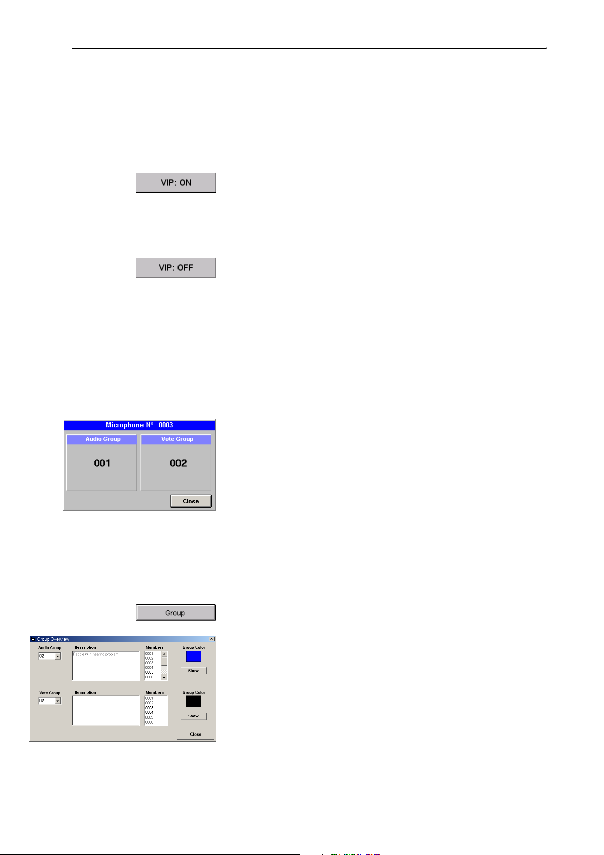
Monitoring and controlling a conference
Configuring the VIP mode
VIP units are marked with a little blue square in the upper left corner of the
conference console icon.
To switch the VIP mode off:
왘 Move the mouse pointer to the left-hand margin of the screen.
The tool palette opens.
왘 In the tool palette, click the “VIP: ON” button.
The little blue squares disappear from the conference console icons. All
conference consoles configured as VIP units (see “Configuring VIP
units” on page 36) loose the VIP rights. The button changes to “VIP:
OFF”.
To switch the VIP mode on:
왘 In the tool palette, click the “VIP: OFF” button.
The blue squares are displayed on the confernce console icons. All
conference consoles configured as VIP units (see “Configuring VIP
units” on page 36) obtain the VIP rights.The button changes to “VIP:
ON”.
Displaying the group assignment of a conference console during a conference
To display the audio group and voting group assignment of a conference
console during a conference:
왘 Press the “Ctrl” key and keep it pressed.
왘 Right-click the conference console whose group assignments you want
to display.
The dialog box for displaying groups opens. The numbers of the audio
group and the voting group to which the conference console is assigned
are displayed.
To close this dialog box:
왘 Click the “Close” button.
Displaying the overview of groups during a conference
To display the overview of groups during a conference:
왘 Move the mouse pointer to the left-hand margin of the screen.
The tool palette opens.
왘 In the tool palette, click the “Group” button.
The “Group Overview” dialog box opens.
76
왘 From one of the two drop down lists “Audio Group” or “Vote Group”,
choose the number of the group to be displayed.
The description of the selected group and the group color are displayed.
(You cannot edit the description and the group color in this dialog box.)
In addition, the microphone numbers of all conference consoles
assigned to the selected group are displayed in the “Members” list.
왘 Click the “Show” button.
In the synoptic view, all conference consoles assigned to the selected
group are highlighted in the group color of the group.
To return to the normal display:
Page 77

Monitoring and controlling a conference
왘 In the “Group Overview” dialog box, click the “Close” button.
All conference consoles are displayed in their original color instead of
the group color.
Changing the audio settings during a conference
To change the audio settings during a conference:
왘 Move the mouse pointer to the left-hand margin of the screen.
The tool palette opens.
왘 In the tool palette, click the “Audio Settings” button.
The “Audio Settings” dialog box opens.
왘 If you have created audio groups:
From the “Group” drop down list, choose the number of the audio
group whose audio settings you want to change.
The group color is displayed in the field below the “Group” drop down
list and the description of the group is displayed in the field below the
group color field.
To change the audio setting of all conference console icons, choose
“All” from the “Group” drop down list.
In this case, the group color field and the field displaying the
description of the group remain empty.
왘 In the “Loudspeaker” box, adjust the audio settings for the consoles’
built-in loudspeakers. Here you adjust the same settings as in the
Loudspeaker” menu of the central unit (see “Adjusting the audio
“
settings for the consoles’ built-in loudspeakers” on page 90 of the
SDC 8200 system manual).
왘 In the “Microphone” box, adjust the audio settings for the consoles’
microphones. Here you adjust the same settings as in the
Microphone” menu of the central unit (see “Adjusting the audio
“
settings for the consoles’ microphones” on page 91 of the SDC 8200
system manual).
y The “Volume” slider in the “Loudspeaker” box allows you to set the
volume of the consoles’ built-in loudspeakers.
77
Page 78
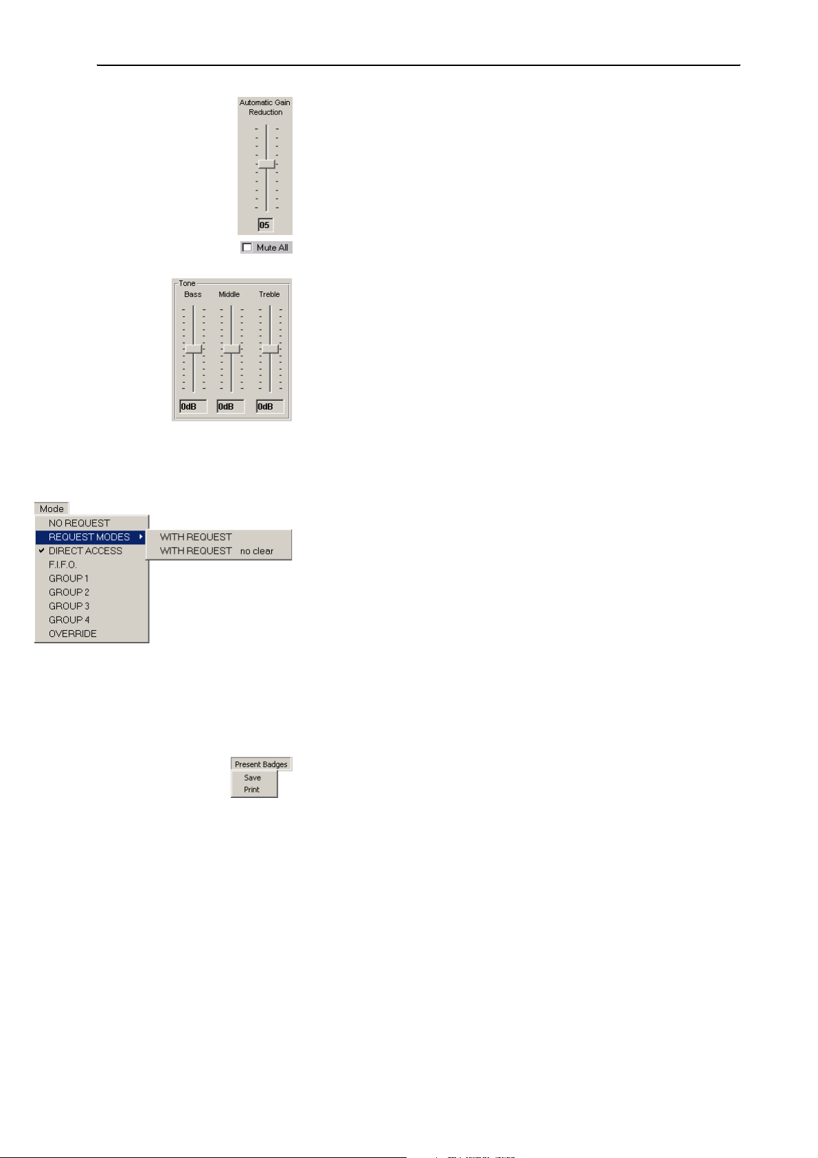
Monitoring and controlling a conference
y The “Automatic Gain reduction” slider in the “Microphone” box
allows you to set the automatic gain reduction of the consoles’ microphones.
y The “Mute All” check box allows you to mute the conference consoles
of all audio groups.
y The “Low”, “Middle”, and “Treble” sliders in the “Tone” boxes allow
you to adjust the bass, middle and treble response of the consoles’
built-in loudspeakers and microphones.
Note:
If you change the audio settings via the central unit’s operating menu,
this is automatically detected by the software and immediately
displayed in the “Audio Settings” dialog box.
Changing the conference mode during a conference
To change the conference mode during a conference:
왘 Make sure that no-one is currently speaking.
When changing the conference mode, all microphones are turned off
automatically!
왘 From the “Mode” menu, choose the desired conference mode.
The setting becomes effective immediately. The new conference mode
is displayed in the “Mode” box of the control palette.
Saving or printing the data of all inserted chip cards
To save the data of all inserted chip cards in a file (e.g. in order to
document the presence of the delegates), you require the SDC 8200 SYS
software:
왘 From the “Present Badges” menu, choose “Save”.
The file selection box opens.
왘 Select a folder, the file name and the extension “mdb” and confirm your
selection by clicking the “OK” button.
All inserted chip cards are read and the data are saved in a database file
in the order of the microphone numbers.
78
Example:
"C:\Programs\SDC8200\S_CM\Data\File.mbd","200401-01","12:00:00",""
"Micro", "Badge", "Name", "Party"
4, 1, "Archer", "USA"
5, 2, "Becker", "GER"
6, 3, "Miller", "CAN"
Page 79

Monitoring and controlling a conference
To print the data of all inserted chip cards:
왘 From the “Present Badges” menu, choose “Print”.
All inserted chip cards are read and the data are printed in the order of
the microphone numbers.
Testing the loudspeakers of the conference consoles
To test the loudspeakers of the connected conference consoles:
왘 From the “Test” menu, choose “Test Generator ON”.
왘 The “Test Generator ON” button is displayed. All active consoles are
deactivated automatically. The central unit transmits a test tone which
is reproduced by all operational conference consoles.
To end the loudspeaker test:
왘 From the “Test” menu, choose “Testgenerator OFF” or click the “Test
Generator ON” button.
The “Test Generator ON” button disappears and the test tone stops.
To test the microphones of the connected conference consoles:
왘 From the “Test” menu, choose “Test all Microphones”.
The “Test all Microphones” button is displayed.
All active consoles are deactivated automatically. All operational
consoles are activated for approx. 1 second each. The microphone
number of the currently active console is displayed on the “Test all
Microphones” button and the signal light ring on the currently active
console lights up.
To end the microphone test:
왘 From the “Test” menu, choose “End Test all Microphones” or click the
“Test all Microphones” button.
The “Test all Microphones” button disappears and the microphone test
is ended.
Creating a text message
To create a text message and display it on the displays of the conference
consoles:
왘 Click the “Message to Delegates” menu.
The “Message to Delegates” window opens.
79
Page 80

Monitoring and controlling a conference
왘 Enter the message in the “Message” box.
You can enter a maximum of 40 characters.
Note:
Special characters such as accents and umlauts are not displayed
correctly on the displays.
To send the message to all delegates:
왘 Click the “All delegates” option button.
왘
Click the “Send message” button.
The message is sent to the displays of all connected conference consoles.
To send the message to a certain delegate:
왘 Click the “Delegate N°” option button and enter the microphone
number in the field on the right of the option button or select the name
of the delegate from the drop down list box.
왘 Click the “Send message” button.
The message is sent to the display of the selected conference console.
왘 Select the next delegate to receive this message and click the “Send
message” button again.
To clear the message from the “Message” box:
왘 Click the “Clear message” button.
The message is cleared from the “Message” box.
Triggering acoustic signals
You can use two different acoustic signals, e.g. to announce the beginning
of the conference or the start of the voting session. You can select the
signal via the options (see “Configuring acoustic signals” on page 45).
To trigger an acoustic signal:
왘 In the voting window, click one of the buttons “Bell” or “Start”.
The signal is output via the sound card of the PC.
80
Page 81
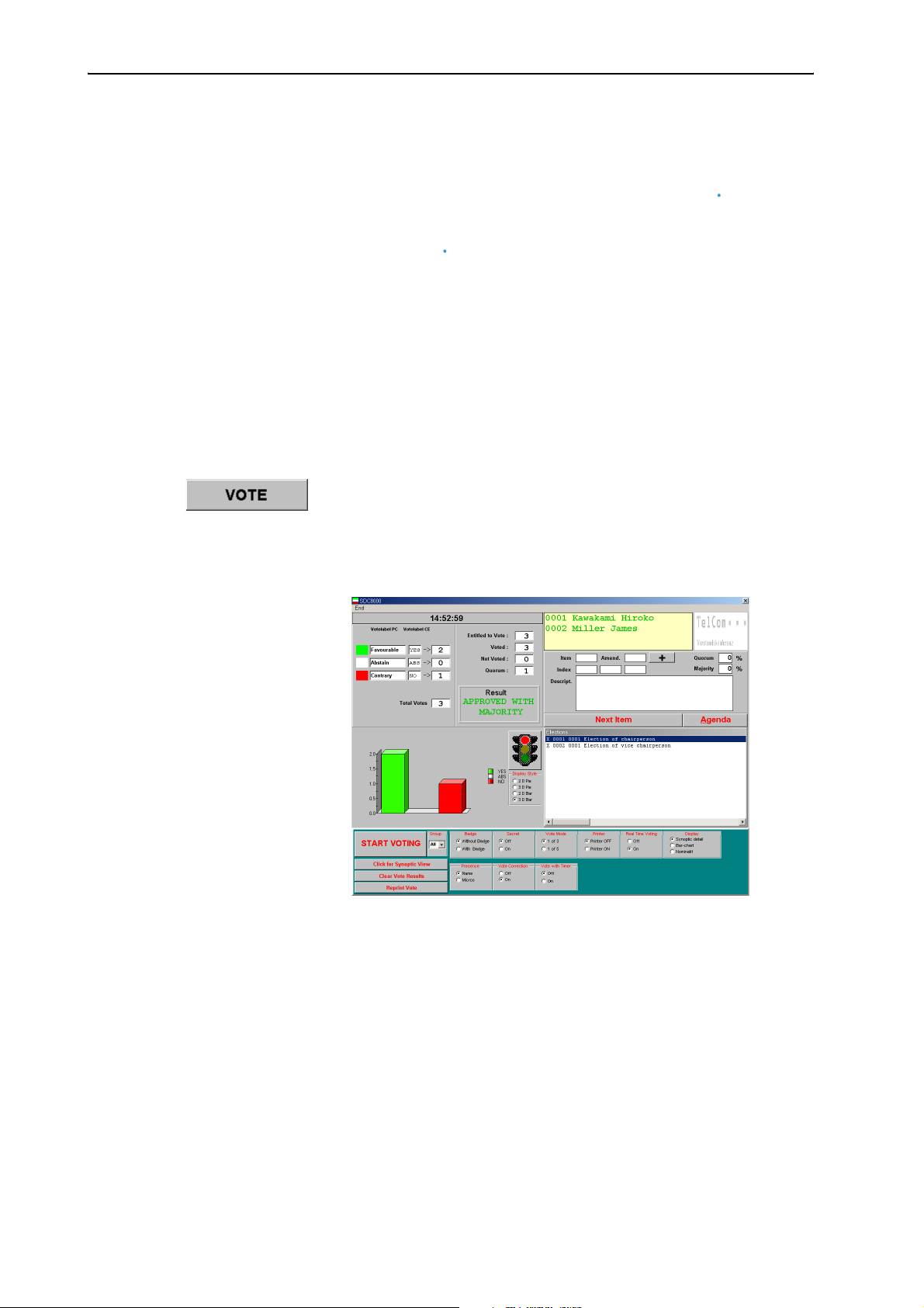
Voting
Note:
All conference consoles have at least three voting keys , allowing you
to take votes in “1 of 3” mode.
The SDC 8200 CV and SDC 8200 DV conference consoles have five
voting keys ,, allowing you to take votes in “1 of 3” and “1 of 5”
mode.
In order to be able to take votes in “1 of 5” mode, you require the
SDC 8200 SYS software.
쏹
쏹
Loading the agenda file
To start a vote or a series of votes:
왘 Move the mouse pointer to the left-hand margin of the screen.
The tools palette opens.
왘 Click the “VOTE” button.
The file selection box opens.
쏹
쏹
Voting
왘 Select an agenda file and confirm your selection by clicking the “OK”
button.
The voting window opens.
The left-hand side of the window shows:
y the current time of the current voting item,
y the name of the three or five voting options (colors/abbreviations on
the displays of the conference consoles) and the voting result in
numbers,
y a graphic representation of the voting result (circle or bar graph).
81
Page 82

Voting
The right-hand side of the window shows:
y a yellow box in which the names of the delegates who make a request
to speak are shown in green (if you click one of the names with the
left mouse button, the corresponding delegate is assigned the
“speaking right”),
y if specified – two logos which appear one above the another (on the
top right) (see “Configuring the voting settings” on page 42),
y the “Next Item” and the “Agenda” buttons and
y the loaded agenda file (Agenda).
The lower part of the window shows:
y the buttons for starting and ending the votes (on the left) and
y the voting settings (on the right).
Changing the agenda
You can change the agenda until shortly before the vote starts:
왘 Click the “Agenda” button.
The agenda opens.
82
Page 83

Voting
Selecting the voting settings
Choosing the voting groups
To restrict votes to certain conference participants, you first have to define
voting groups as described under “Defining groups” on page 34.
왘 From the “Group” drop down list, choose the number of the voting
group which is to participate in the vote.
To allow all participants to participate in the vote, choose “All” from the
“Group” drop down list.
Taking votes with or without chip cards
To restrict votes to conference participants owning a chip card, you require
the SDC 8200 SYS software.
To take votes without chip cards:
왘 In the “Badge” box, click the “Without Badge” option button.
The delegates can cast their vote without a chip card.
To take votes with chip cards:
왘 In the “Badge” box, click the “With Badge” option button.
The delegates can only cast their vote when their chip cards are
inserted into the chip card slots of their conference consoles and the
green LED on the chip card icon lights up.
Taking secret or public votes
To take a secret vote:
왘 In the “Secret” box, click the “ON” option button.
y If you click the “Synoptic detail” option button, the selected voting
option (YES, ABS, NO or 1, 2, 3, 4, 5) is not displayed in the synoptic
view.
y After a delegate has cast his or her vote, all LEDs on his or her console
light up so that no one can see how he or she has voted.
y If you automatically print the voting results (see “Automatically
printing the voting results” on page 84), the printout does not
contain information on the delegates.
y The voting protocol files (which are automatically saved in the folder
“C:\Programs\SDC8200\S_CM”) do not contain information on
the voting behaviour of the individual delegates.
To take a public vote:
왘 In the “Secret” box, click the “OFF” option button.
y If you click the “Synoptic detail” option button, the selected voting
option (YES, ABS, NO or 1, 2, 3, 4, 5) is displayed by color in the
synoptic view.
y After a delegate has cast his or her vote, the LED corresponding to the
voting option lights up on his or her console so that everyone can see
how he or she has voted.
83
Page 84

Voting
y If you automatically print the voting results (see “Automatically
printing the voting results” on page 84), the selected voting option
(YES, ABS, NO or 1, 2, 3, 4, 5) appears next to the name of the
delegate on the printout.
y The vote log files (which are automatically saved in the folder
“C:\Programs\SDC8200\S_CM”) contain information on the
voting behaviour of the individual delegates.
Selecting the voting mode
To select the voting mode “1 of 3”:
왘 In the “Vote Mode” box, click the “1 of 3” option button.
The delegates can vote “Yes” or “No” or abstain.
To select the voting mode “1 of 5”:
Note:
In order to be able to take votes in “1 of 5” mode, all conference
consoles used must have five voting keys (SDC 8200 CV or
SDC 8200 DV). In addition, you require the SDC 8200 SYS software.
쏹
쏹
왘 In the “Vote Mode” box, click the “1 of 5” option button.
The delegates have the choice of five options.
Automatically printing the voting results
To automatically print all voting results:
왘 Make sure that the printer is connected and configured correctly and
turned on.
왘 In the “Printer” box, click the “ON” option button.
After the vote is completed, the voting result is printed automatically.
To suppress the automatic printing of the voting results:
왘 In the “Printer” box, click the “OFF” option button.
After the vote is completed, the voting result is not printed. However,
you can seperately print the voting result of any vote at any time (see
“Printing voting results” on page 89).
Displaying how votes are cast
To display how votes are cast:
왘 In the “Real Time Voting” box, click the “ON” option button.
The display of the votes already cast is continuously updated until
voting ends. If the delegates can see this display (e.g. via the video PC),
this could influence their voting behaviour.
84
To prevent that the votes already cast are displayed during voting:
왘 In the “Real Time Voting” box. click the “OFF” option button.
Page 85
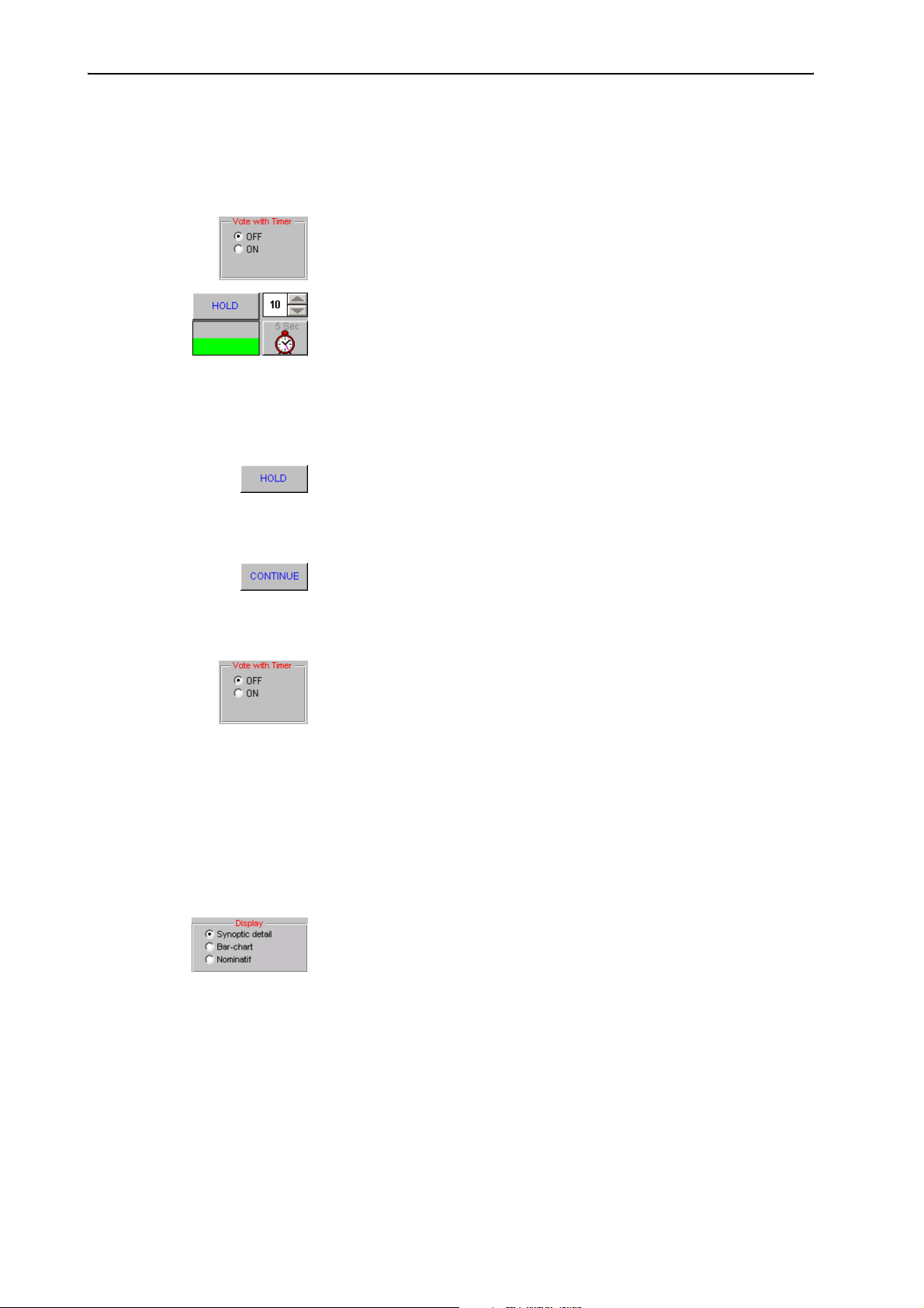
Specifying the voting time
You can specify a fixed voting time. If delegates do not vote during this
time, their votes become invalid.
To specify a fixed voting time:
왘 In the “Vote with Timer” box, click the “ON” option button.
The “Max. voting time” list box and the clock are displayed.
왘 Click one of the arrows in the “Max. voting time” list box to specify the
voting time (in seconds).
왘 Start the vote (see “Taking votes” on page 87).
The countdown begins. The green bar turns gray one section at a time.
The clock is displayed and the countdown is shown in seconds.
To temporarily stop the countdown:
왘 Click the “HOLD” button.
The countdown is stopped. The delegates can also cast their votes
while the countdown is on hold.
Voting
To continue the countdown:
왘 Click the “CONTINUE” button.
The countdown continues. Votes cast after completion of the voting
time are invalid.
To not limit the voting time:
왘 In the “Vote with Timer” box, click the “OFF” option button.
Voting does not end until you click the “STOP VOTING” button.
Configuring the display of the voting results on the video PC
To configure the display style on the video PC:
왘 Start the vote (see “Taking votes” on page 87).
During voting, a bar chart always appears on the monitor, large screen
display or projector connected to the video PC. The bar chart is only
continuously updated during voting if the “ON” option button in the
“Real Time Voting” box is selected.
왘 After the vote is completed, click the desired option button in the
“Display” box.
85
Page 86

Voting
y If you select “Synoptic detail”, the synoptic view of the conference is
shown on the video PC. Each console icon is marked with a color
symbolizing the vote cast. A palette on the right-hand margin shows
what the colors mean.
y If you select “Bar-chart”, the voting result is shown as a bar or circle
chart on the video PC. The votes cast for one option and the total
votes cast are also displayed as a number.
86
Page 87
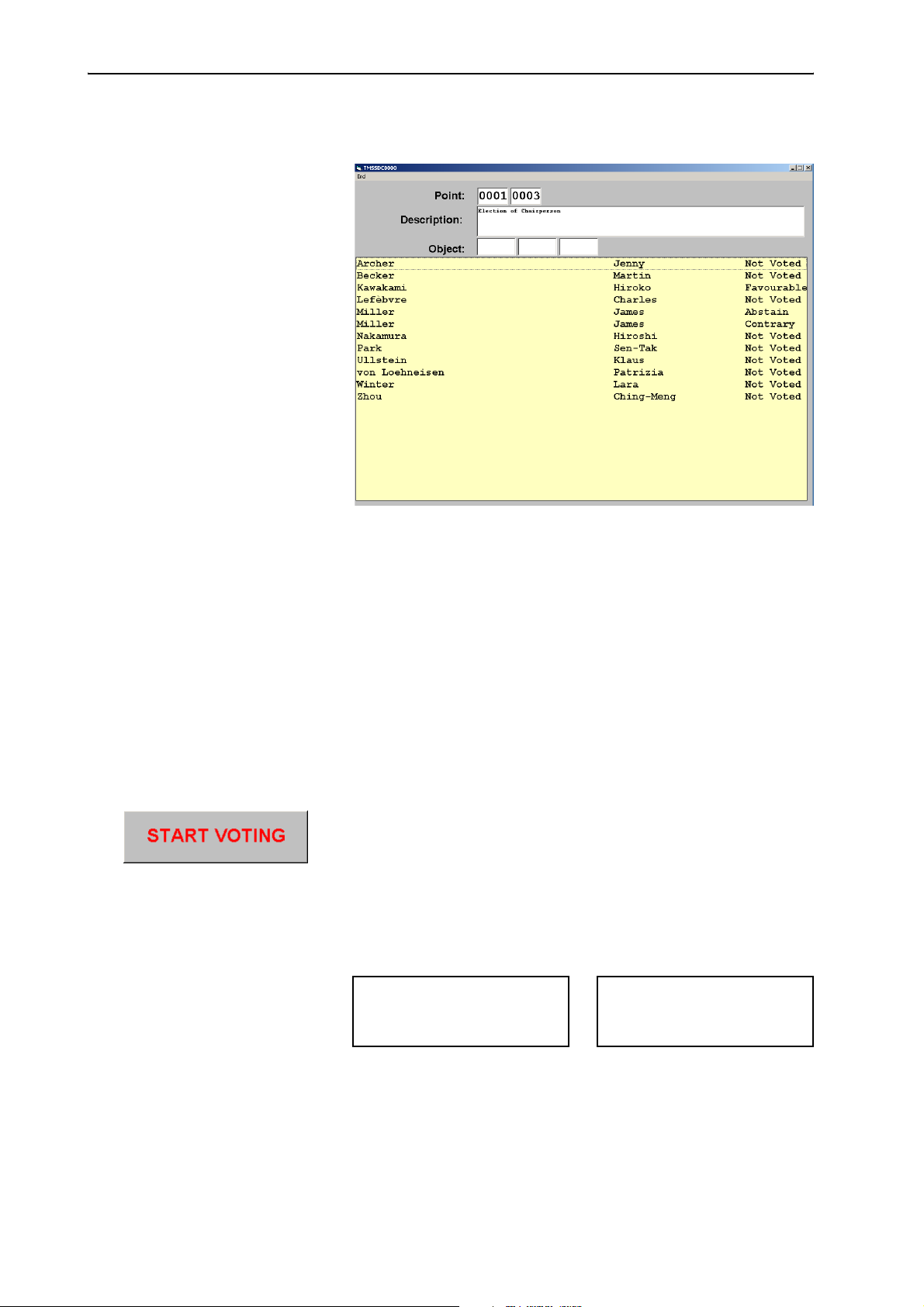
Voting
y If you select “Nominatif”, the names of all delegates and the votes
they cast are displayed in clear text.
Taking votes
Starting a vote
To start a vote:
왘 Load the desired agenda file (see “Loading the agenda file” on
page 81).
왘 Make sure that all options are configured correctly (see “Selecting the
voting settings” on page 83).
왘 In the agenda, click the vote to be started.
왘 Click the “START VOTING” button.
The signal light in the “summary” area turns green. If a video PC is
connected, the signal light turns green here too as a signal to the
delegates that they are now expected to vote (see “Configuring the
display of the voting results on the video PC” on page 85).
The displays of the consoles with voting function display the voting
modes “Vote 1 of 3” or “Vote 1 of 5“:
Mic N.: 1024
VOTE 1 OF 3
YES ABS NO
Mic N.: 1024
VOTE 1 OF 5
12345
If the “Vote with timer ON” option is selected, the countdown begins
(see “Using the “Global” option button in the “Speech Timer” box” on
page 69).
As long as voting is still in progress, the delegates can change their vote
whenever they want!
87
Page 88

Voting
Ending a vote
A vote is ended:
y automatically when the countdown is over,
y manually if you click the “STOP VOTING” button.
After the vote is completed:
y the agenda displays an “x” in front of the voting item which has just
stopped and the latter automatically moves to the end of the agenda,
y the summary shows the votes cast for all available options as well as the
total votes cast,
y the voting window displays a chart which illustrates the voting result
(you can change the style of this chart at any time by selecting a
different option in the “Display Style” area),
y the voting result is displayed on a video PC (if connected),
y the displays of the consoles display the votes cast for the available
options (see “Configuring the display of the voting results on the video
PC” on page 85),
y the voting result is printed automatically if the “Printer ON” option is
selected (see “Automatically printing the voting results” on page 84),
y the safety folder (see “Configuring the log files” on page 47) saves two
protocol files which contain all voting details – including the voting
result.
To delete the display of the voting result on the master PC and all
connected video or slave PCs:
왘 Click the “Clear Vote Results” button.
All that is deleted is the display of the voting results. The saved
protocol files with the voting results are not deleted. The system is now
ready for voting again.
Assigning the votes cast to the delegates
To see which vote a certain delegate cast:
Note:
It is only possible to assign the votes cast to the delegates if the “Secret
OFF” option button is selected (see “Taking secret or public votes” on
page 83).
왘 Click the “Click for Synoptic View” button.
The synoptic view is displayed. The console icons appear in the color
which corresponds to the vote cast (see also the color legend in the
summary).
Note:
You can display further details on a connected video PC (see
“Configuring the display of the voting results on the video PC” on
page 85).
88
Page 89

Voting
Printing voting results
To exceptionally print a voting result from a series of votes:
왘 Click the “Reprint Vote” button.
The file selection box opens.
왘 Select the voting results to be printed and confirm your selection by
clicking the “OK” button.
The selected voting results are printed.
To automatically print each voting result:
왘 Click the “Printer ON” option button (see “Automatically printing the
voting results” on page 84).
The voting result is automatically printed after the vote is completed.
Repeating a vote
To repeat a vote:
왘 In the agenda, click the vote which has already been taken and which
you want to repeat.
왘 Press the “Del” key.
The “x” in front of the vote which has already been taken disappears.
왘 Click the “START VOTING” button again.
The vote is repeated.
Automatically proceeding to the next voting item
Once you have completed a vote from the agenda, you can automatically
proceed to the next voting item on the agenda using the “Next Item”
button.
왘 Click the “Next Item” button.
The subject and details of the voting item at the very top of the agenda
are displayed in the status area on the top left of the voting window.
You can start this vote immediately by clicking the “START VOTING”
button.
89
Page 90

Ending the “Confsys” program
Ending the “Confsys” program
To end the “Confsys” program:
왘 Click “End” on the menu bar.
The program is ended. If consoles are active when you exit the program,
they remain active. The conference is not interrupted, but is now
controlled via the central unit only.
90
Page 91
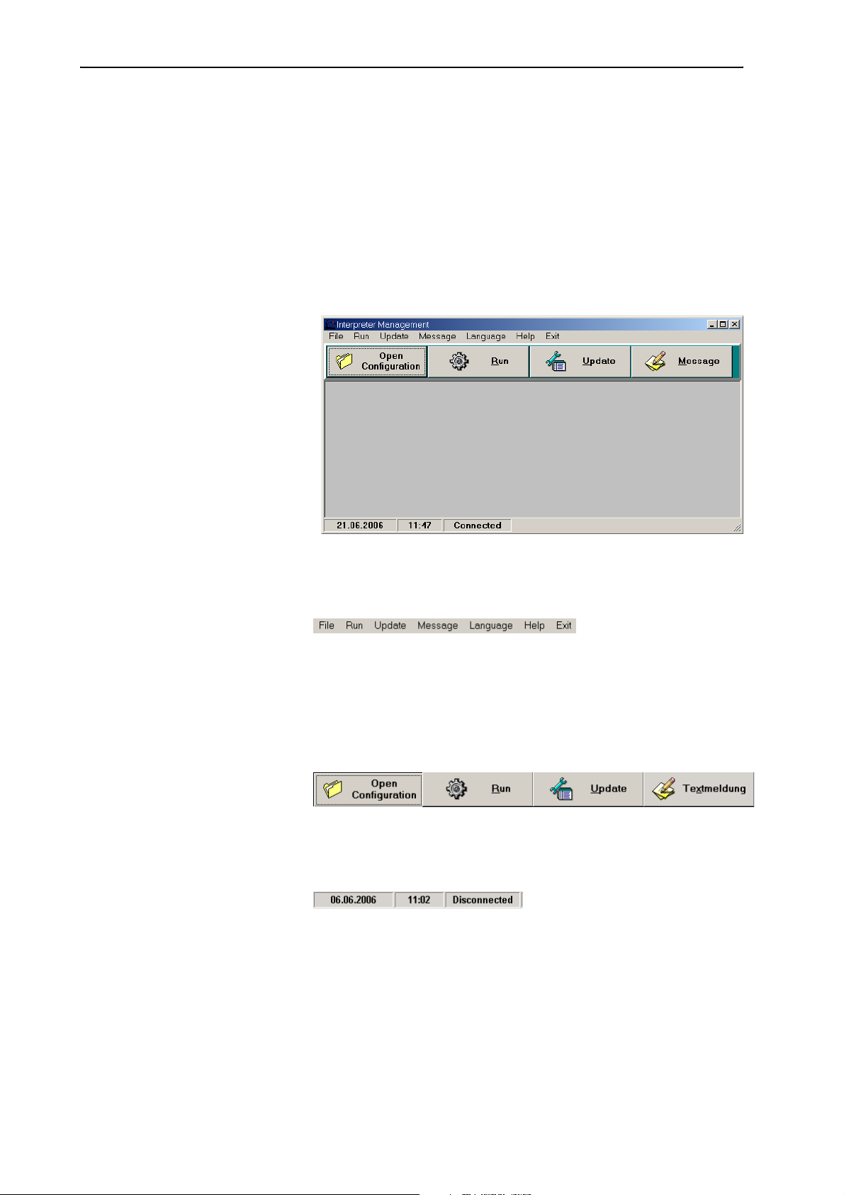
Configuring the interpretation system
Configuring the interpretation system
This chapter provides information on how to quickly and easily configure
the consoles of your interpretation system (but not the consoles of the
conference system) using the software.
For configuring the interpretation system, you require the S-IM
(Interpreter Management) software module which is started as follows:
왘 Click “Start” and select “Programs”, “SDC 8200” and “S_IM” one after
the other. The click “Intsys”.
The “Interpreter Management” window opens.
The “Interpreter Management” window consists of:
y the menu bar
y the buttons
To open an
interpretation
configuration:
To monitor the
status of the
interpreter
consoles during
the conference:
To change the
language for the
B-channel:
To send text
messages to
displays of the
interpreter consoles:
y the status bar
(displays the date, the time and the status of the COM connection)
91
Page 92
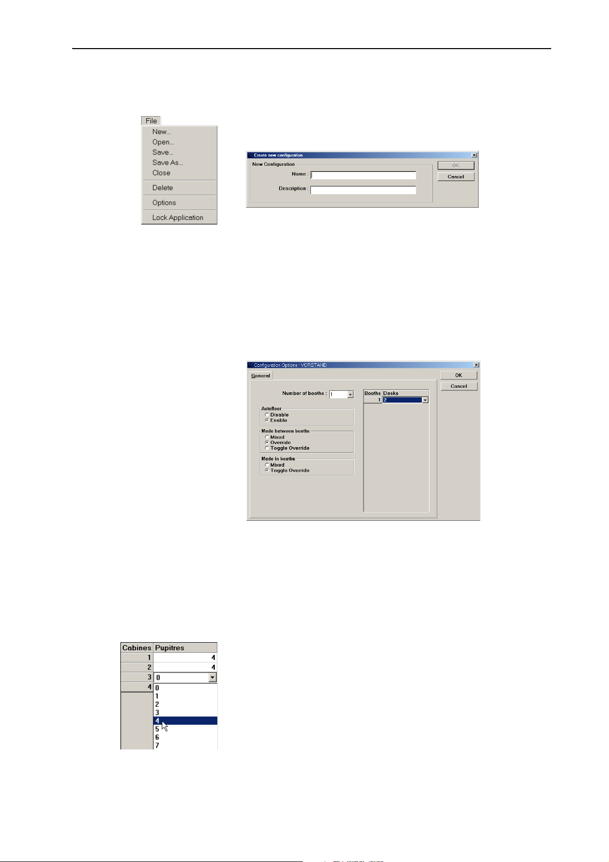
Configuring the interpretation system
Creating an interpretation configuration
To create a new interpretation configuration:
왘 From the “File” menu, choose “New...”.
The “Create new configuration” window opens.
왘 In the “Name” field, enter the name of the interpretation configuration
to be created (eight characters max.).
왘 In the “Description” field, enter a description of the interpretation
configuration to be created.
왘 Click the “OK” button.
A subfolder with the name of the interpretation configuration is
created in the folder “C:\Programs\SDC8200\S_IM” and all data
of the configuration are saved in this subfolder.
The “Configuration Options” window opens.
92
왘 From the “Number of booths” drop down list box, select the total
number of interpreter booths in your configuration:
y If you are using the SDC 8200 SYS software, you can manage up to 28
languages.
y If you are using the SDC 8200 SYS-M software, you can only manage
four languages.
For each booth, a row is added to the table on the right.
왘 In each row of the table, click the “Desks” column.
The “Desks” drop down list box opens.
왘 From each “Desks” drop down list box, select the number of interpreter
consoles installed in the corresponding booth.
y If you are using the SDC 8200 SYS software, you can configure up to
28 interpreter consoles per booth.
y If you are using the SDC 8200 SYS-M software, you can only configure
up to two interpreter consoles per booth.
Page 93

Configuring the interpretation system
왘 Configure the following options according to your conference
requirements:
y Autofloor
y Mode between booths
y Mode in booths
Note:
For information on the auto-floor function, see “Enabling the autorelay interpretation function (Auto-floor)” on page 101 of the
SDC 8200 system manual; for information on the operating modes
between or within the interpreter booths, see “Configuring the
operating mode between booths” on page 98 and “Configuring the
operating mode within a booth” on page 99 of the SDC 8200 system
manual.
왘 Click the “OK” button.
The “Desk Language Assignment” window opens (see “Assigning
languages to the interpreter booths” on page 94).
Opening an interpretation configuration
To open an existing interpretation configuration:
왘 From the “File” menu, choose “Open...” or click the “Open
Configuration” button in the “Interpreter Management” window.
The “Open Configuration” window opens.
왘 Click the configuration you want to open and confirm your selection by
clicking the “OK” button.
The “Desk Language Assignment” window opens (see “Assigning
languages to the interpreter booths” on page 94).
93
Page 94

Configuring the interpretation system
Deleting an interpretation configuration
To delete an existing interpretation configuration:
왘 From the “File” menu, choose “Delete”.
The “Delete Configuration” window opens.
왘 Click the configuration you want to delete and click the “Delete”
button.
A dialog box opens.
왘 Confirm the deletion of the selected configuration by clicking the “OK”
button.
The subfolder with the name of the interpretation configuration is
deleted from the folder “C:\Programs\SDC8200\S_IM” and all
parameters of the configuration are deleted.
Assigning languages to the interpreter booths
After you have created or opened an interpretation configuration, the
“Desk Language Assignment” window opens.
The “Desk Language Assignment” window contains:
y the language table (on the left),
y the booth table,
y the interpreter console boxes (“Desk 1”, “Desk 2”, etc.) and
y the “Send”, “Reset”, “Deskinit”, “Options” and “Serial Numbers”
buttons (on the right).
94
Page 95

Configuring the interpretation system
Editing the language table
The language table contains the languages and their assigned
abbreviations. After initialization, the abbreviations are displayed on the
displays of the interpreter consoles. You can edit the language table.
Note:
The abbreviations and names of the languages comply with ISO 639.2.
To add languages and abbreviations to the language table:
왘 Click an empty row at the bottom of the table.
왘 In the “Abbr.” field, enter the abbreviation for the language (three
characters max.) which is to be displayed on the consoles’ displays.
왘 In the “Language” field, enter the name of the language (ten
characters max.).
The language is added to the language table.
To change a language or abbreviation in the language table:
왘 Click the row you want to change.
The abbreviation and the name of the selected language appear in the
“Abbr.” and “Language” fields.
왘 Change the abbreviation and the name of the language in the “Abbr.”
and “Language” fields.
To delete a language or abbreviation from the language table:
왘 Click the row you want to delete.
The abbreviation and the name of the selected language appear in the
“Abbr.” and “Language” fields.
왘 Click the “Delete” button.
The language is deleted from the language table of this configuration.
Assigning an interpreter booth its main target language (A-channel)
To assign an interpreter booth its main target language (A-channel):
왘 In the booth table, click the booth to which you want to assign its main
target language.
The channel number of the selected booth is displayed in the “Channel”
field. A drop down arrow for selecting the language appears in the
“Language” column.
왘 Click the drop-down arrow in the “Language” column and select the
language you want to assign to the selected booth.
The selected main target language is displayed in the “Language” field
and in the “Language” column of the booth table.
The channel number and the abbreviation for the language are
displayed in the upper right corner of the interpreter console display
next to the channel key “A”.
To change the language assignment for the A-channel:
왘 In the booth table, click the booth whose main target language you
want to change.
The channel number of the selected booth is displayed in the “Channel”
field and the language is displayed in the “Language” field. The drop
95
Page 96

Configuring the interpretation system
down arrow for selecting the language appears in the “Language”
column.
왘 Click the drop down arrow in the “Language” column and select the
new main target language you want to assign to the selected booth.
The selected language is displayed in the “Language” box.
To delete the language assignment for the A-channel:
왘 In the booth table, click the booth whose main target language you
want to delete.
The channel number of the selected booth is displayed in the “Channel”
field and the language is displayed in the “Language” field. The drop
down arrow for selecting the language appears in the “Language”
column.
왘 Click the “Delete” button.
The language assignment is deleted and the selected booth is no longer
assigned any language.
Preconfiguring the languages for the B-channel of an interpreter console
Apart from the main target language (A-channel), you can preconfigure a
second target language (B-channel). The interpreters can change the
configuration of the B-channel at any time during the conference (see
“Configuring the B-channel of an interpreter console” on page 38 of the
SDC 8200 system manual). You can also change the preconfiguration of
the B-channel during the conference (see “Changing the language for the
B-channel of an interpreter console during the conference” on page 107).
To preconfigure the second target language (B-channel) of an interpreter
console:
왘 In the booth table, click the booth whose interpreter consoles you want
to assign a specific language for the B-channel.
The interpreter console boxes of the interpreter consoles installed in
this booth are displayed.
왘 In the desired interpreter console box, click the “B channel” box.
The “B channel” dialog box opens.
The “B channel” dialog box contains the “B channel” box on the left, the
“Channel” and “B channel” lists and – on the right – the check boxes for
activating the other interpreter consoles installed in this booth. The
arrow buttons in the middle allow you to move the languages from one
list to the other:
96
y Click the button to move the first language from the “Channel” list
to the “B channel” list.
Page 97

Configuring the interpretation system
y Click the button to move all languages from the “Channel” list to
the “B channel” list.
y Click the button to move the first language from the “B channel”
list back to the “Channel” list.
y Click the button to move all languages from the “B channel” list
back to the “Channel” list.
To assign an interpreter console one or several languages for the Bchannel, add the desired languages to the “B channel” list:
왘 In the “B channel” box, click the “Some” option button.
왘 In the “Channel” list, click the languages you want to add to the
“B channel” list one after the other or click one of the buttons or .
The selected languages are moved to the “B channel” list. The selection
is displayed in the corresponding interpreter console box.
Via the interpreter console, the interpreter can now select a language
for the B-channel from the “B channel” list (see “Configuring the Bchannel of an interpreter console” on page 38 of the SDC 8200 system
manual).
Languages which are not in the “B channel” list cannot be selected for
the B-channel.
If you only add a single language to the “B channel” list, the interpreter
can only select this language for the B-channel.
To remove languages from the “B channel” list:
왘 In the “B channel” list, click the languages you want to remove one
after the other or click one of the buttons or .
The selected languages are moved back to the “Channel” list.
To assign an interpreter console all available languages for the B-channel:
왘 In the “B channel” box, click the “All” option button.
All languages are moved to the “B channel” list and are displayed in
grey.
The interpreter can now select any of these languages for the Bchannel via the interpreter console (see “Configuring the B-channel of
an interpreter console” on page 38 of the SDC 8200 system manual).
To prevent that the interpreter interprets into a second language, you can
block the B-channel:
왘 In the “B channel” box, click the “None” option button.
All languages are moved to the “Channel” list and are displayed in grey.
The interpreter can no longer select a language for the B-channel via
the interpreter console. He can only interpret into the main target
language (A-channel).
97
Page 98
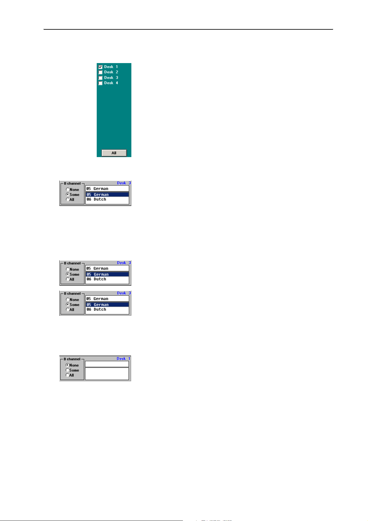
Configuring the interpretation system
To assign the selection made to several interpreter consoles of the selected
booth:
왘 In the right hand part of the “B channel” dialog box, click the check
boxes of the interpreter consoles to which the selection made is to be
assigned. To assign the selection made to all interpreter consoles of the
booth, click the “All” button.
To specifically assign an interpreter console a single language for the Bchannel:
왘 In the corresponding interpreter console box, click the “All” option
button.
The list box for selecting the language is displayed.
왘 In the list box, click the language you want to assign to the B-channel
of the selected interpreter console.
The language is displayed in the box above the list box and is assigned
to the B-channel of the selected interpreter console.
To prevent that the interpreter selects a different language for the Bchannel:
왘 In the corresponding interpreter console box, click the “All” option
button.
The list box for selecting the language is displayed.
왘 In the interpreter console box, click the “Some” option button.
왘 In the list box, click the language whose selection you want to prevent
and click the “Delete” button. Repeat for additional languages if
necessary.
The languages are deleted and can no longer be selected by the
interpreter.
To completely deactivate the B-channel:
왘 In the corresponding interpreter console box, click the “None” option
button.
The selection of a language for the B-channel via this console is no
longer possible.
98
Page 99

Configuring the interpretation system
COM port, menu language and password
To configure the COM port and the menu language or to change the
password:
왘 From the “File” menu, choose “Options”.
The “Options” window opens.
Configuring the COM port
To configure the COM port of the PC connected to the SDC 8200 CU central
unit:
왘 From the “COM” drop down list box in the “Serial Communications
Port” box, select the COM port of the PC connected to the COM 3
interface of the central unit.
If you click a COM port which is not available on your PC, a dialog box
with the message “COMx not available” appears (“x” corresponds to
the COM port number).
If you do not know the correct COM port, try the different options one after
the other:
왘 Then click the “Test” button.
y If a dialog box with the message “Test is successful on COMx”
appears, the PC can communicate with the central unit via the
selected COM port. Your conference system is now ready for
operation.
y If a dialog box with the message “Test failed on COMx” appears, you
have to try a different COM port.
Configuring the menu language
To change the menu language of the IM software module:
왘 From the drop down list box in the “Language” box, select the desired
menu language.
99
Page 100

Configuring the interpretation system
Changing the password
To change the password:
왘 Click the “Change Password” button.
The “Change Password” dialog box opens.
왘 In the “Old Password” box, enter the current password (see “The two
passwords” on page 12).
왘 In the “New Password” box, enter the new password.
왘 In the “Confirm Password” box, re-enter the new password.
왘 Click the “OK” button to save the new password; click the “Cancel”,
button to keep the current password.
Locking the Interpreter Manangement software
If you need to leave your PC during a conference, you can secure your
interpretation configuration and prevent unauthorized use by locking the
software:
왘 From the “File” menu, choose “Lock Application”.
The password dialog box opens.
왘 Enter the password and click the “OK” button.
The Interpreter Management software is locked.
To unlock the Interpreter Management software:
왘 From the “File” menu, choose “Lock Application”.
The password dialog box opens.
왘 Enter the password and click the “OK” button.
The Interpreter Management software is unlocked.
100
 Loading...