

Sennheiser SDC 8000 User Manual
S
C 8000
System Manual
Conference System
D

Thank you for choosing Sennheiser!
We have designed these products to give you reliable operation over many
years. Over half a century of accumulated expertise in the design and
manufacture of high-quality electro-acoustic equipment have made
Sennheiser a world-leading company in this field.
Please take a few moments to read these instructions carefully, as we want
you to enjoy your new Sennheiser products quickly and to the fullest.
2

Contents
Contents
Safety information ........................................................................................................................................................ 8
SDC 8000 – the digital conference and interpretation system ............................................................................... 9
Overview of the components of the
SDC 8000 system ......................................................................................................................................................... 10
The conference consoles ...................................................................................................................................................... 10
The interpreter consoles ...................................................................................................................................................... 11
The central unit ..................................................................................................................................................................... 11
The system cables ................................................................................................................................................................. 11
The software control ............................................................................................................................................................ 11
The technology used ............................................................................................................................................................ 12
The components of the SDC 8000 system in detail ................................................................................................ 13
The consoles ........................................................................................................................................................................... 13
SDC 8000 D conference unit ......................................................................................................................................... 15
SDC 8000 C chairman unit ............................................................................................................................................. 16
SDC 8000 DC conference unit ....................................................................................................................................... 17
SDC 8000 CC chairman unit ........................................................................................................................................... 18
SDC 8000 DV conference unit ....................................................................................................................................... 19
SDC 8000 CV chairman unit .......................................................................................................................................... 20
SDC 8000 ID interpreter console .................................................................................................................................. 21
The SDC 8000 CU central unit ............................................................................................................................................. 22
The SDC 8000 AO analog output unit (optional) ........................................................................................................... 23
The system cables ................................................................................................................................................................. 24
Operating the components of the
SDC 8000 system ......................................................................................................................................................... 25
Operating the delegate units .............................................................................................................................................. 25
Taking the floor / Making a request to speak ........................................................................................................... 25
Turning off the microphone / Cancelling a request to speak ................................................................................. 28
Adjusting the volume of the headphones connected to a conference console .................................................. 29
Selecting an interpretation channel ............................................................................................................................ 29
Voting ................................................................................................................................................................................ 29
Using the chip card slot of a conference console ...................................................................................................... 30
Operating the VIP units ........................................................................................................................................................ 30
Operating the chairman unit .............................................................................................................................................. 30
Turning all active conference consoles off (priority) ............................................................................................... 30
Starting a voting session ............................................................................................................................................... 31
Assigning a participant the “speaking right” ........................................................................................................... 31
Showing the request-to-speak list on the displays of the conference consoles ................................................ 32
Operating the interpreter consoles ................................................................................................................................... 33
Adjusting the volume and the middle and treble response of the headphones connected to the interpreter
console .............................................................................................................................................................................. 33
Adjusting the volume of the interpreter consoles’ built-in loudspeakers .......................................................... 33
Configuring the B-channel of an interpreter console .............................................................................................. 33
Setting the channel to be output via the interpreter console’s built-in loudspeaker ...................................... 34
Selecting an interpretation channel ............................................................................................................................ 34
Using the interpreter console ....................................................................................................................................... 34
Switching between the A-channel and the B-channel ............................................................................................ 35
Muting the microphone of the interpreter console .................................................................................................. 35
Displaying text messages on the interpreter console’s display ............................................................................ 35
3

Contents
Operating the central unit ................................................................................................................................................... 35
Adjusting the volume of the consoles’ built-in loudspeakers ............................................................................... 35
The F1, F2 and F3 menu keys ....................................................................................................................................... 36
The menu operating controls ....................................................................................................................................... 36
Working with the central unit’s operating menu ..................................................................................................... 37
Structuring the SDC 8000 system ............................................................................................................................. 38
Interconnecting the conference/interpreter consoles ............................................................................................. 38
Connecting cable strings to a central unit ................................................................................................................. 38
Interconnecting up to 10 central units ....................................................................................................................... 38
The three expansion stages ................................................................................................................................................ 38
Expansion stage (1): one central unit with up to 15 consoles .............................................................................. 39
Expansion stage (2): one central unit with up to 90 consoles .............................................................................. 39
Expansion stage (3): several central units with up to 900 consoles .................................................................... 40
Determining maximum cable lengths ............................................................................................................................... 40
Calculating the voltage drop on the system cables ................................................................................................. 41
Structuring an interpretation system ............................................................................................................................... 41
Selectable modes between or within interpreter booths ............................................................................................. 42
Mode between booths: “Mixed“ .................................................................................................................................. 42
Mode between booths: “Override” .............................................................................................................................. 42
Mode between booths: “Toggle Override” ................................................................................................................ 42
Mode in booths: “Mixed” ............................................................................................................................................... 43
Mode in booths: “Override” .......................................................................................................................................... 43
The “auto-floor” function ............................................................................................................................................. 43
Using external equipment ................................................................................................................................................... 45
Connecting external audio sources ............................................................................................................................. 45
Transmitting the floor channel and the interpretation channels to broadcasting and TV stations .............. 45
Transmitting the floor channel or an interpretation channel
via a PA system ............................................................................................................................................................... 46
Transmitting the floor channel and the interpretation channels via an infrared transmission link ............. 46
Setting up the SDC 8000 system ............................................................................................................................... 47
Preparing the SDC 8000 system components for set up .............................................................................................. 47
Conference and interpreter consoles .......................................................................................................................... 47
Central unit ...................................................................................................................................................................... 47
Fixing the cell transmitter feet .................................................................................................................................... 47
Rack-mounting several central units .......................................................................................................................... 47
Interconnecting the SDC 8000 system components ...................................................................................................... 48
Interconnecting the consoles ....................................................................................................................................... 48
Connecting a cable string to the central unit ............................................................................................................ 48
Interconnecting several central units ......................................................................................................................... 48
Turning the central units on and off ........................................................................................................................... 49
Connecting additional equipment ..................................................................................................................................... 49
Connecting external audio sources ............................................................................................................................. 50
Carrying out remote conferences ................................................................................................................................ 50
Connecting PA systems, recording units, etc. ........................................................................................................... 51
Pin assignment of the 9-pole sub-D socket (AUX OUT 2-3-4-5) .......................................................................... 51
Connecting an SDC 8000 AO analog output unit to the central unit ................................................................... 51
Daisy-chaining SDC 8000 AO analog output units ................................................................................................... 52
Connecting external equipment to the SDC 8000 AO’s phoenix connector ........................................................ 52
Connecting a PC to the central unit ............................................................................................................................. 53
Configuring the SDC 8000 system ............................................................................................................................. 54
Introduction to the central unit’s operating menu ........................................................................................................ 54
The start display ............................................................................................................................................................. 54
4

Contents
The six main menus ........................................................................................................................................................ 54
The submenus of the “Conference” menu (part 1 of 6) ......................................................................................... 56
The submenus of the “Conference” menu (part 2 of 6) ......................................................................................... 57
The submenus of the “Conference” menu (part 3 of 6) ......................................................................................... 58
The submenus of the “Conference” menu (part 4 of 6) ......................................................................................... 59
The submenus of the “Conference” menu (part 5 of 6) ......................................................................................... 60
The submenus of the “Conference” menu (part 6 of 6) ......................................................................................... 61
The submenus of the “Interpretation” menu (part 1 of 5) .................................................................................... 62
The submenus of the “Interpretation” menu (part 2 of 5) .................................................................................... 63
The submenus of the “Interpretation” menu (part 3 of 5) .................................................................................... 64
The submenus of the “Interpretation” menu (part 4 of 5) .................................................................................... 65
The submenus of the “Interpretation” menu (part 5 of 5) .................................................................................... 66
The submenus of the “Aux-In/Out” menu (part 1 of 6) ......................................................................................... 67
The submenus of the “Aux-In/Out” menu (part 2 of 6) ......................................................................................... 68
The submenus of the “Aux-In/Out” menu (part 3 of 6) ......................................................................................... 69
The submenus of the “Aux-In/Out” menu (part 4 of 6) ......................................................................................... 70
The submenus of the “Aux-In/Out” menu (part 5 of 6) ......................................................................................... 71
The submenus of the “Aux-In/Out” menu (part 6 of 6) ......................................................................................... 72
The submenus of the “System” menu (part 1 of 2) ................................................................................................ 73
The submenus of the “System” menu (part 2 of 2) ................................................................................................ 74
The submenus of the “Language” and the “License” menu (part 1 of 1) .......................................................... 75
Setting the volume of the consoles’ built-in loudspeakers .......................................................................................... 76
Configuring the conference system .................................................................................................................................. 76
Turning on the central unit for the first time ............................................................................................................ 76
Automatically initializing all conference consoles ................................................................................................... 76
Manually initializing all conference consoles ............................................................................................................ 77
Loading the factory-preset default configuration for the conference system .................................................. 77
Adding a conference console to an already existing configuration ..................................................................... 77
Removing a conference console from an already existing configuration ........................................................... 78
“Reserving” a microphone number ............................................................................................................................. 78
Selecting a conference mode ........................................................................................................................................ 79
Setting the speaker limit ............................................................................................................................................... 80
Adjusting the audio settings for the consoles’ built-in loudspeakers ................................................................. 80
Adjusting the audio settings for the consoles’ microphones ................................................................................ 81
Resetting the conference system ................................................................................................................................ 81
Testing the consoles’ built-in loudspeakers .............................................................................................................. 82
Testing the consoles’ microphones ............................................................................................................................. 82
Activating/deactivating the flashing of the signal light ring ................................................................................ 82
Configuring the display of the voting options .......................................................................................................... 83
Configuring the interpretation system ............................................................................................................................. 83
Working with the interpreter configuration ............................................................................................................. 83
Creating a new interpreter configuration .................................................................................................................. 84
Modifying the currently active interpreter configuration ...................................................................................... 85
Loading a previously saved interpreter configuration ............................................................................................ 85
Options .............................................................................................................................................................................. 86
Setting the max. number of interpreter booths/languages .................................................................................. 86
Setting the max. number of interpreter consoles per booth ................................................................................. 86
Configuring the operating mode between booths ................................................................................................... 87
Configuring the operating mode within a booth ...................................................................................................... 87
Configuring the language options for the interpreter booths ............................................................................... 88
Configuring the main target language (A-channel) of a booth ...................................................................
Configuring the second target language (B-channel) of a booth ......................................................................... 88
Enabling the auto-relay interpretation function (Auto-floor) .............................................................................. 89
Half-automatically initializing all interpreter consoles on the central unit ........................................................ 90
Manually assigning an interpreter console an individual booth number ............................................................ 90
Manually assigning an interpreter console an individual desk number (interpreter console number) ........ 91
......... 88
5

Contents
Displaying the booth and desk number of an interpreter console ....................................................................... 92
Adding interpreter consoles to an existing configuration ..................................................................................... 92
Loading the factory-preset default configuration for the interpretation system ............................................. 93
Resetting the interpretation system .......................................................................................................................... 93
Configuring the audio inputs and outputs ...................................................................................................................... 94
Choosing the audio inputs and outputs ..................................................................................................................... 94
Adjusting the volume of the audio outputs .............................................................................................................. 94
Assigning a channel to an audio output .................................................................................................................... 95
Turning the audio inputs or outputs on and off ....................................................................................................... 95
Configuring the audio outputs for remote conferencing ........................................................................................ 95
Adjusting the input level of an audio input .............................................................................................................. 96
Adjusting the input sensitivity of an audio input .................................................................................................... 96
Configuring the outputs of the SDC 8000 analog output unit .............................................................................. 96
Making a system diagnosis ................................................................................................................................................. 98
Displaying the number of consoles connected to the central unit ....................................................................... 98
Checking the communication within a cable string ................................................................................................. 98
Configuring connected additional components .............................................................................................................. 98
Camera control ................................................................................................................................................................ 98
Turning on a connected control panel ........................................................................................................................ 98
Configuring an “ambient sound” console .................................................................................................................. 99
Software, language and license ...................................................................................................................................... 100
Displaying the version number of the central unit’s software ........................................................................... 100
Choosing the language of the central unit’s operating menu ............................................................................ 100
Displaying the central unit’s serial number ............................................................................................................ 101
Displaying the license code of your conference and interpretation system .................................................... 101
Upgrading the license of your conference and interpretation system ............................................................. 101
If problems occur... .................................................................................................................................................... 102
Replacing a fuse ........................................................................................................................................................... 102
Conference/interpreter console does not work ..................................................................................................... 102
Only the microphone of the chairman unit can be activated ............................................................................. 102
Maintenance and care ............................................................................................................................................... 102
Accessories ................................................................................................................................................................. 103
System components .................................................................................................................................................... 103
Software ........................................................................................................................................................................ 103
System cables ............................................................................................................................................................... 103
Licenses .......................................................................................................................................................................... 103
Specifications ............................................................................................................................................................. 104
Consoles ............................................................................................................................................................................... 104
SDC 8000 D .................................................................................................................................................................... 104
SDC 8000 C .................................................................................................................................................................... 104
SDC 8000 DC ................................................................................................................................................................. 105
SDC 8000 CC .................................................................................................................................................................. 105
SDC 8000 DV ................................................................................................................................................................. 106
SDC 8000 CV .................................................................................................................................................................. 106
SDC 8000 ID .................................................................................................................................................................. 107
SDC 8000 CU central unit ................................................................................................................................................. 108
SDC 8000 AO analog output unit .................................................................................................................................... 109
RJ 45 cable ...................................................................................................................
........................................................ 109
6

Contents
Appendix A:
Camera control protocol ........................................................................................................................................... 110
Appendix B:
Control panel protocol .............................................................................................................................................. 112
Appendix C:
Repeater for the SDC 8000 system ......................................................................................................................... 114
7

Safety information
Safety information
The Sennheiser SDC 8000 conference and interpretation system is state of
the art and has been designed to meet the regulations in force.
Nevertheless, the individual components of the SDC 8000 conference and
interpretation system can cause danger for persons and material assets if:
y the system is not used as intended,
y the system is set up by personnel not familiar with the safety
regulations,
y the system is converted or altered incorrectly,
y the following safety instructions are not observed.
Warning!
If the components of the conference and interpretation system are set
up improperly, persons can stumble over cables, fall and suffer serious
injury! This can also cause severe damage to units and cables.
Place the components of the system on flat surfaces only. Lay the
cables in such a way that no-one can stumble over them.
Attention!
The central units generate heat! If the heat generated cannot dissipate,
the central units can be destroyed or combustible materials nearby can
catch fire.
Make sure that the air vents of the central units are not covered or
blocked. Keep combustible materials away from the central units.
Attention!
If liquids or small parts which conduct electricity find their way into the
interior or to the sockets or plug contacts of the units, this can cause a
short circuit which may damage the units!
Keep liquids and small parts which conduct electricity away from the
units! Before cleaning the units, disconnect all central units from the
mains by removing the plug. For cleaning the system components, only
use a slightly damp cloth. Do not use solvents as they can damage the
surfaces.
Attention!
If you connect defective or unsuitable accessories, the system
components can be destroyed!
Only use the connection cables available from Sennheiser electronic
GmbH (see “The system cables” on page 24). Sennheiser makes no
warranty as to cables not manufactured by Sennheiser.
Warning!
This is a class A product. In a domestic environment this product may
cause radio interference in which case the user may be required to take
adequate measures.
8

SDC 8000 – the digital conference and interpretation system
SDC 8000 – the digital conference and
interpretation system
The new SDC 8000 conference and interpretation system from Sennheiser
utilizes all advantages of digital communications technology and offers its
users a series of important features:
y Decentralized, clear sound reproduction
y Excellent speech intelligibility due to 16-bit audio transmission
y Easy installation and straight-forward operation
y Conference consoles are extremely easy to operate
y Delegate interaction (e.g. with voting sessions)
y Interpretation facility
y Extended functionality
y Possibility of connecting an infrared language distribution system
SDC stands for S
of mobile and expandable conference and interpretation equipment.
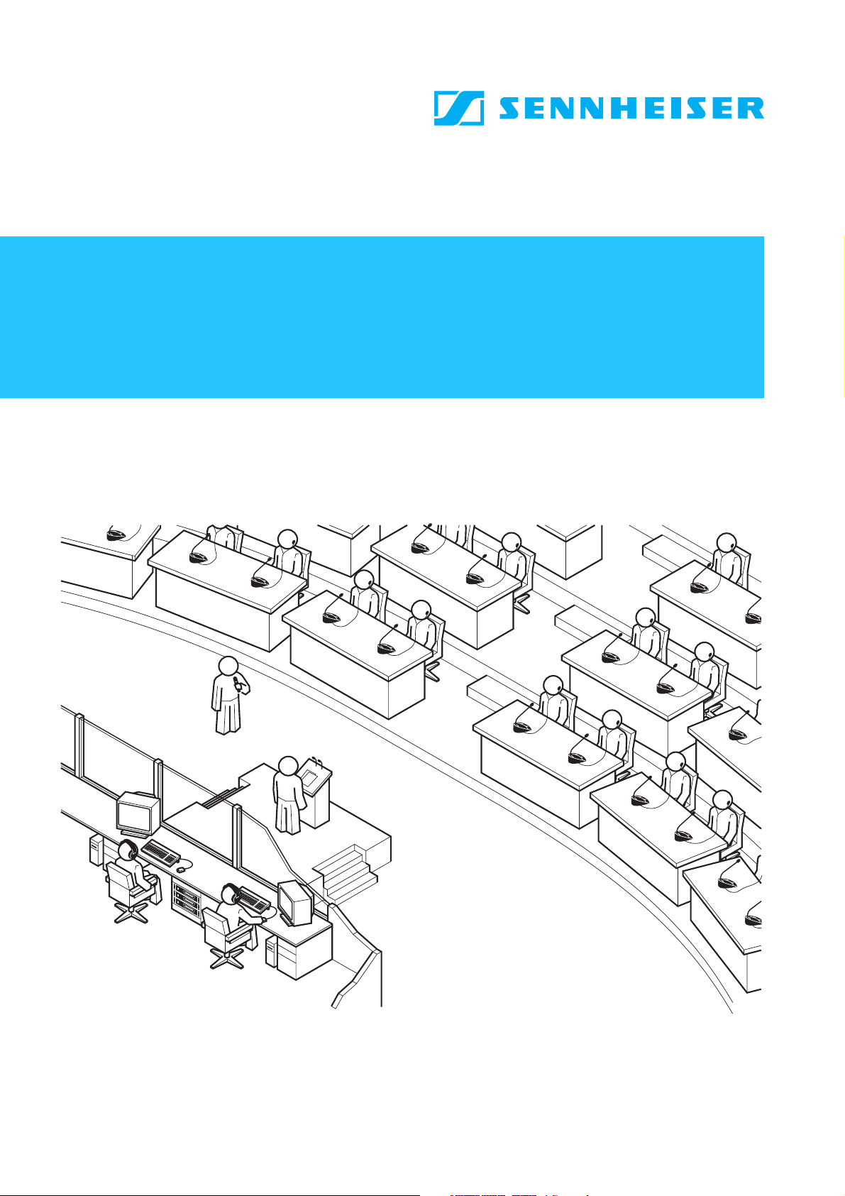
The SDC 8000 conference and interpretation system is an ideal choice for
both small seminars with up to 15 participants and large international
conferences with a maximum of 900 participants.
An important feature of the SDC 8000 conference and interpretation
system is its modular design. Even if, at first, the system is only required
for small conferences, you can later easily add conference consoles and a
software control program. In any case, the conference and interpretation
system can:
y be set up quickly, since all consoles are connected in series (single-cable
system),
y be adapted easily to any room and any number of participants.
ennheiser Digital Conference System – the new generation
9

Overview of the components of the SDC 8000 system
Overview of the components of the
SDC 8000 system
An SDC 8000 conference and interpretation system consists of the
following components:
y Conference consoles for delegates and chairmen
y Interpreter consoles
y Central units
y System cables
y If required, a software control for the conference and interpretation
system
The conference consoles
The conference console features a built-in loudspeaker, allowing the
participant to directly hear all audio information, e.g. speeches,
presentations or any other audio material. This decentralized
“loudspeaker system” ensures excellent sound quality at a pleasant
volume throughout the entire room.
The console’s electret microphone transmits every word in excellent audio
quality. The red signal light ring on the microphone serves as an indicator
of who is allowed to take the floor.
The conference consoles are available in six different versions with varying
levels of functions. Via special consoles with voting function, the
conference participants can participate in voting sessions from the
consoles.
The conference consoles are connected in series. One cable string can
comprise up to 15 conference consoles and up to six cable strings (i.e. up
to 90 conference consoles) can be connected to a single central unit. You
can, however, interconnect several central units to set up conference
systems with up to 900 consoles.
10
DkZgk^Zld[i]ZXdbedcZcihd[i]ZH98-%%%hnhiZb
I]Z^ciZgegZiZgXdchdaZh
I]Z^ciZgegZiZgXdchdaZ^cXdgedgViZhVaa[jcXi^dchd[VXdc[ZgZcXZXdchdaZ
Wjid[[ZghVYY^i^dcVa[ZVijgZhgZfj^gZYWni]Z^ciZgegZiZgh#
I]Z ^ciZgegZiZg XdchdaZh VgZ gZfj^gZY ^[h^bjaiVcZdjh ^ciZgegZiVi^dc ^h
d[[ZgZYViVXdc[ZgZcXZ#
I]ZXZcigVajc^i
I]ZXZcigVajc^i^hi]ZXdgZd[i]ZH98-%%%Xdc[ZgZcXZVcY^ciZgegZiVi^dc
hnhiZbVcY!Vii]ZhVbZi^bZ!hZgkZhVhVc^ciZg[VXZ[dgVYY^i^dcVaVjY^d
hnhiZbh#
K^Vi]ZXZcigVajc^i¼hdeZgVi^c\bZcj!i]ZXdc[ZgZcXZVcY^ciZgegZiVi^dc
hnhiZbXVcWZXdc[^\jgZY[dgVcngddb!VcncjbWZgd[eVgi^X^eVcihVcY
VcnXdc[ZgZcXZjhZ#
I]ZXZcigVajc^ihZgkZhidbVcV\Zi]ZZci^gZXdc[ZgZcXZVcY^ciZgegZiVi^dc
hnhiZb#
Dc i]Z XZcigVa jc^i! nd j XVc X]d dhZ WZilZZc c^cZ Xdc[ZgZcXZ bdYZh#
=dlZkZg!i]ZhZaZXi^dcd[hdbZd[i]ZXdc[ZgZcXZbdYZhdcanbV`ZhhZchZ
^[ndjgXdc[ZgZcXZVcY^ciZgegZiVi^dchnhiZb^hE8XdcigdaaZY#
I]Z XZcigVa jc^i ]Vh V Wj^ai"^c edlZg hjeean [dg edlZg^c\ je id .%
Xdc[ZgZcXZXdchdaZh#;dgaVg\ZgXdc[ZgZcXZhnhiZbh!jeid&%XZcigVajc^ih
XVcWZ^ciZgXdccZXiZY#
I]Z^ciZgegZiVi^dcXVeVX^in d[i]ZXZcigVajc^i^h '-aVc\jV\Zh#KVg^djh
a^XZchZhVgZVkV^aVWaZ[dg[djg!Z^\]i dg '- ^ciZgegZiVi^dc X]VccZah#I]Z
[addgX]VccZaVcYild ^ciZgegZiVi^dc X]VccZah XVc WZdeZgViZYa^XZchZ"
[gZZ#
I]ZhnhiZbXVWaZh
EdlZghjeeand[i]ZXdc[ZgZcXZXdchdaZh^hk^Vi]ZhnhiZbXVWaZhl]^X]
VahdigVchb^ii]ZY^\^iVaVjY^dVcYhiVijh^c[dgbVi^dc#
I]Zhd[ilVgZXdcigda
I]Zdei^dcVahd[ilVgZXdcigdaVaadlhVXdc[ZgZcXZbVcV\ZgidXdcigdai]Z
Zci^gZXdc[ZgZcXZk^VVE8#>cXdcigVhiidXdcigdaa^c\i]ZXdc[ZgZcXZk^Vi]Z
XZcigVajc^i!i]Zhd[ilVgZXdcigdaegdk^YZhhZkZgVaZmigV[jcXi^dch/
&&

Overview of the components of the SDC 8000 system
y Additional functions for controlling the microphones:
Via the computer screen, the conference manager can easily monitor
which participants have made a request to speak, which participants are
currently speaking, etc. All participants can be identified and displayed
by name. Individual conference consoles can be directly activated or
deactivated by clicking the mouse key.
y Display of voting results as diagrams:
The results of votings can be presented graphically and can, for example,
be displayed via a connected projector. In addition, it is possible to take
voting sessions with chip cards. Chip cards make sure that only those
who have a chip card have access to the voting function.
y Configuration of special conference consoles:
The conference manager can configure more than one chairman unit as
well as VIP units.
y Interpreter management software:
This software module allows the conference manager to quickly and
easily configure the interpreter booths and interpreter consoles (i.e.
assign a language to the A-channel and B-channel of an interpreter
console, choose the operating mode between and within the interpreter
booths, etc.).
y Delegate database:
The delegate database allows the conference manager to centrally
manage delegate information such as name, organization, etc. During
the conference, this information is displayed on the computer screen,
allowing the conference manager to identify the participants who are
currently speaking or those who wish to make a contribution by name.
It is also possible to use the information contained on the chip cards.
The technology used
Both the control and sound transmission of the SDC 8000 conference and
interpretation system are fully digital, resulting in excellent audio. The
language channels are transmitted within a frequency range of 100 Hz to
14 kHz at 16-bit resolution.
The conference consoles are connected to each other and to the central
unit by means of system cables.
12

The components of the SDC 8000 system in detail
The components of the SDC 8000 system in detail
The components described on the following pages are available for the
SDC 8000 conference and interpretation system. The components you
require depend on the desired size and use of the SDC 8000 system.
Your conference and interpretation system can comprise the following
consoles:
y two types of conferences consoles
y the delegate units for the conference participants
y the chairman unit for the chairman
y the interpreter consoles
In addition, your conference and interpretation system must comprise:
y at least one central unit
Optionally, you can connect the following components:
y an analog output unit
y a control panel
y a special “ambient sound” conference console
The consoles
Six conference console versions with varying levels of functions as well as
an interpreter console are available.
All consoles feature:
y a built-in loudspeaker via which the floor channel is output
y a MICRO key for activating the microphone
y a microphone – if the microphone is active, the red signal light ring and
the “Microphone active” LED light up permanently
y a headphone connection with headphone volume control
The chairman units (SDC 8000 C, SDC 8000 CC and SDC 8000 CV)
additionally feature:
y a PRIOR. key for turning off all active delegate units
y a NEXT key for assigning the “speaking right” to the next participant
who has made a request to speak (SDC 8000 C and SDC 8000 CC only).
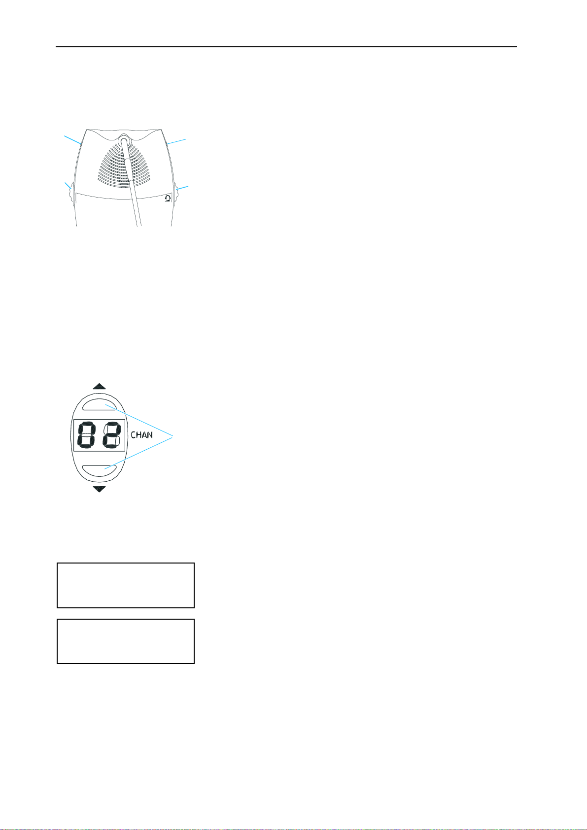
Conference consoles with channel selection keys (SDC 8000 DC, SDC 8000 CC,
SDC 8000 DV and SDC 8000 CV) feature:
y a 2-digit LED channel display for displaying the selected interpretation
channel and two channel selection keys (“CHAN. 왖” and “CHAN. 왔”) for
selecting the interpretation channel.
The selected interpretation channel is output via connected headphones.
Conference consoles with voting function (SDC 8000 CV and SDC 8000 DV)
feature:
y five voting keys with LEDs
13

The components of the SDC 8000 system in detail
y a dot matrix display (122 x 32 dots) for displaying voting options,
voting results and other important information
y a chip card slot for delegate identification
The interpreter console features:
y special “interpretation” functions
y a muting function (MUTE key)
y tone controls for volume, middle and treble of the headphones and a
volume control for the loudspeaker
y a chip card slot
The six conference console versions and the interpreter console are
illustrated in detail on the following pages.
14
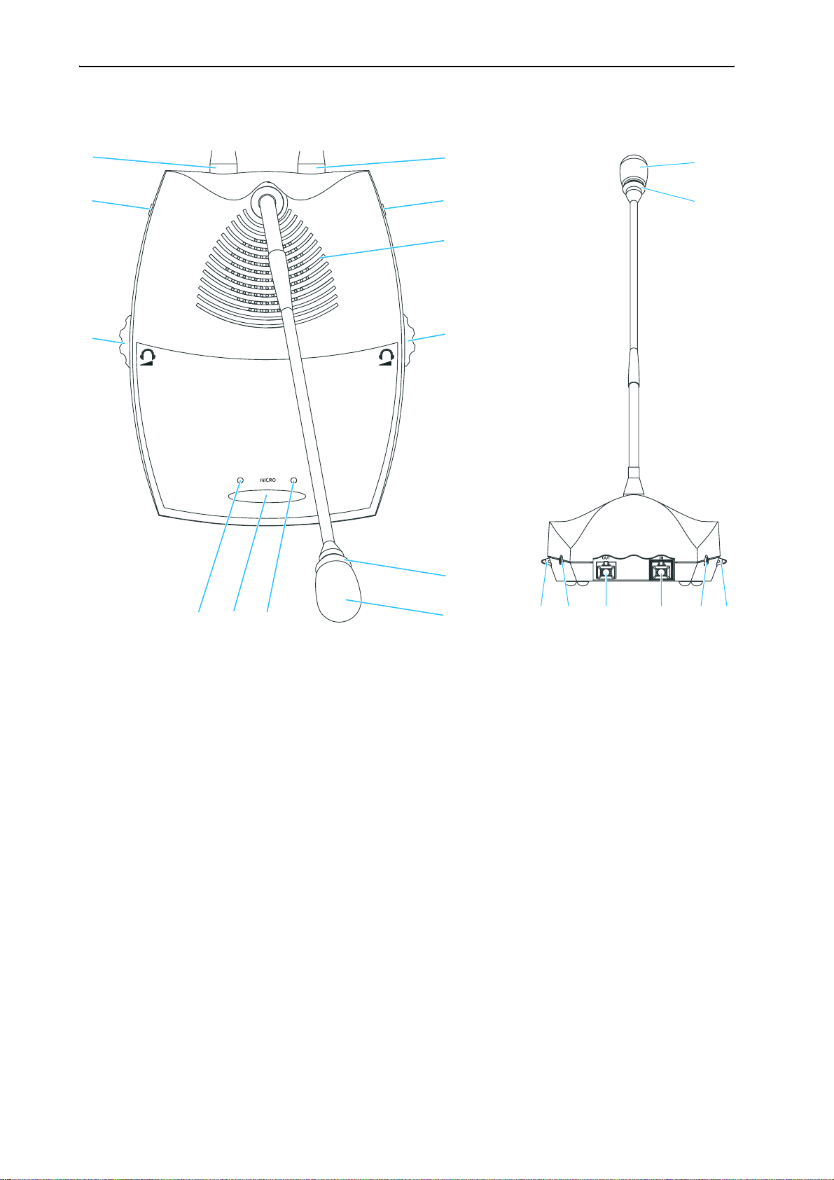
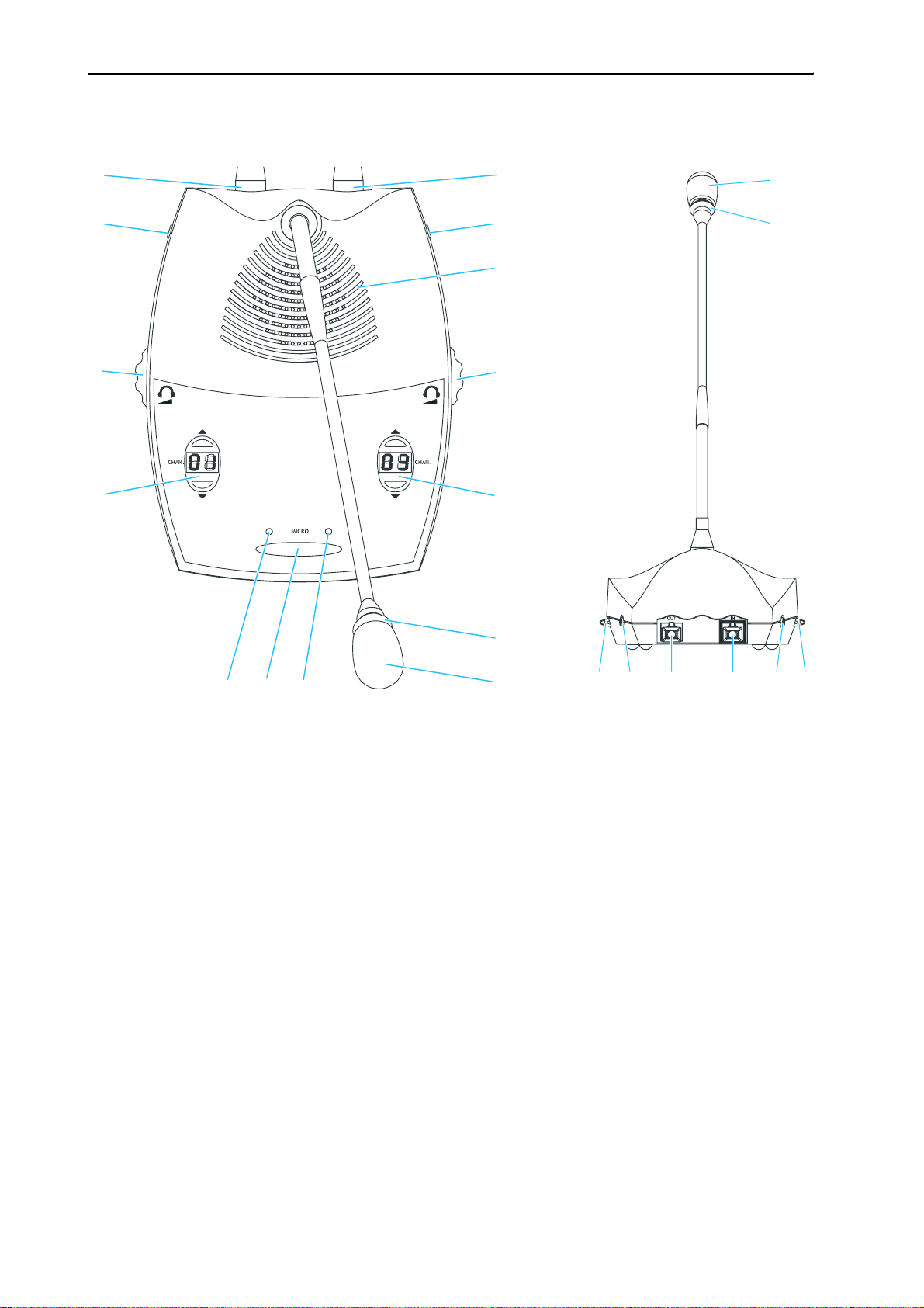
SDC 8000 D conference unit
The components of the SDC 8000 system in detail
22
IN socket (RJ 45)
OUT socket (RJ 45)
Headphone socket (3.5 mm jack)
Loudspeaker
Red signal light ring
Microphone
“Microphone active” LED
MICRO key
“Request to speak” LED
Headphone volume control for headphone socket
Headphone socket (3.5 mm jack)
Headphone volume control for headphone socket
22
15
The components of the SDC 8000 system in detail
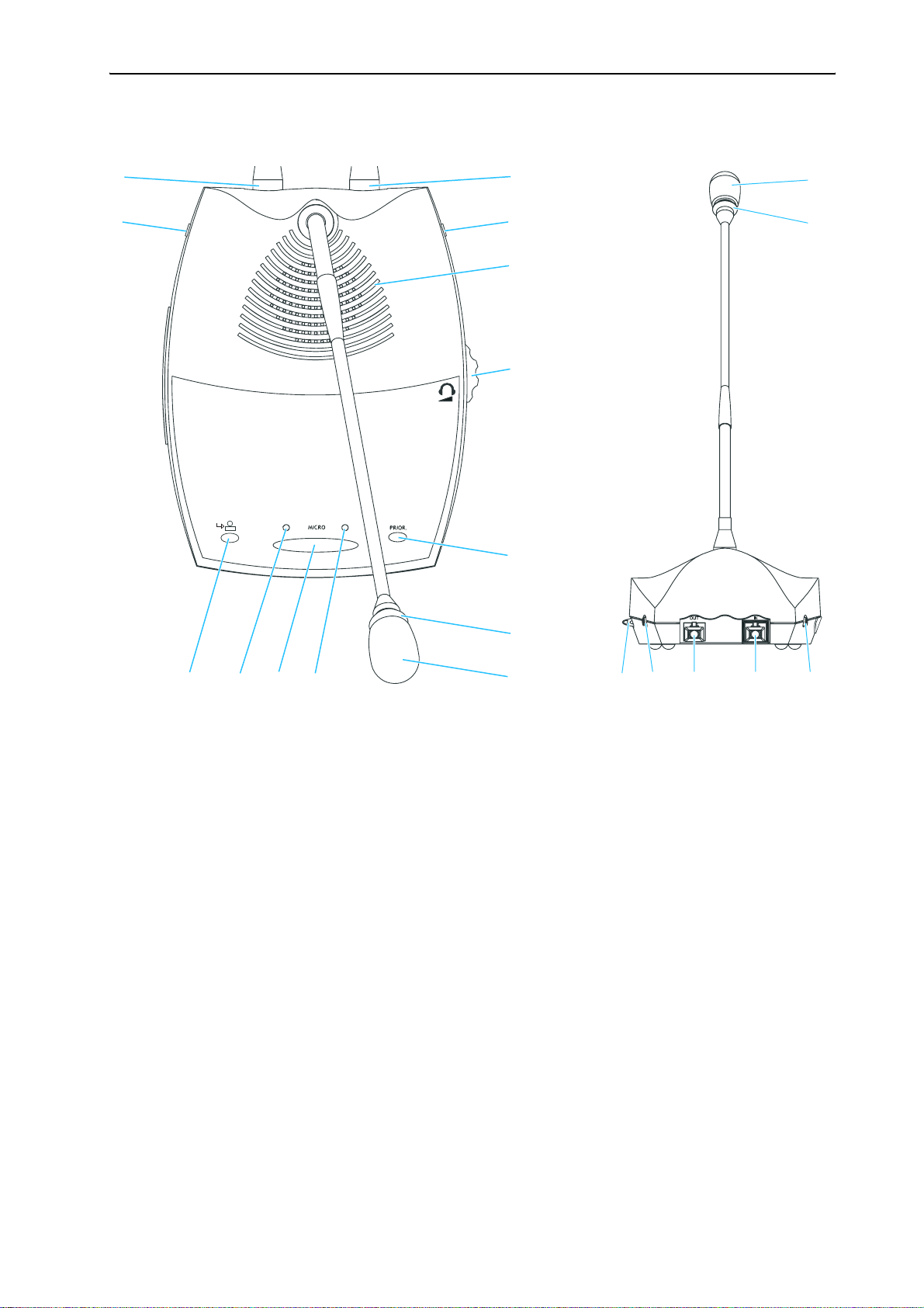
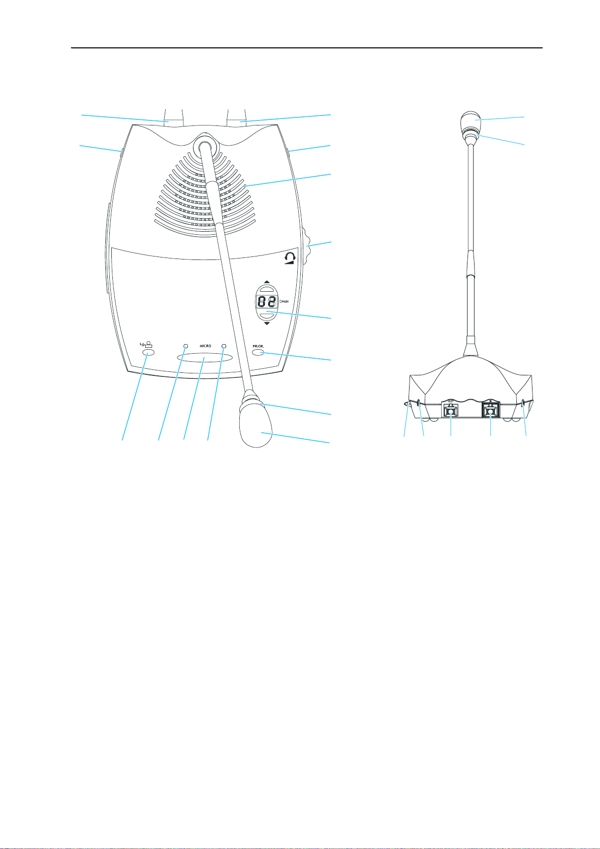
SDC 8000 C chairman unit
IN socket (RJ 45)
OUT socket (RJ 45)
Headphone socket (3.5 mm jack)
Loudspeaker
PRIOR. key
Red signal light ring
Microphone
“Microphone active” LED
MICRO key
“Request to speak” LED
NEXT key
Headphone socket (3.5 mm jack)
Headphone volume control for headphone sockets and
16
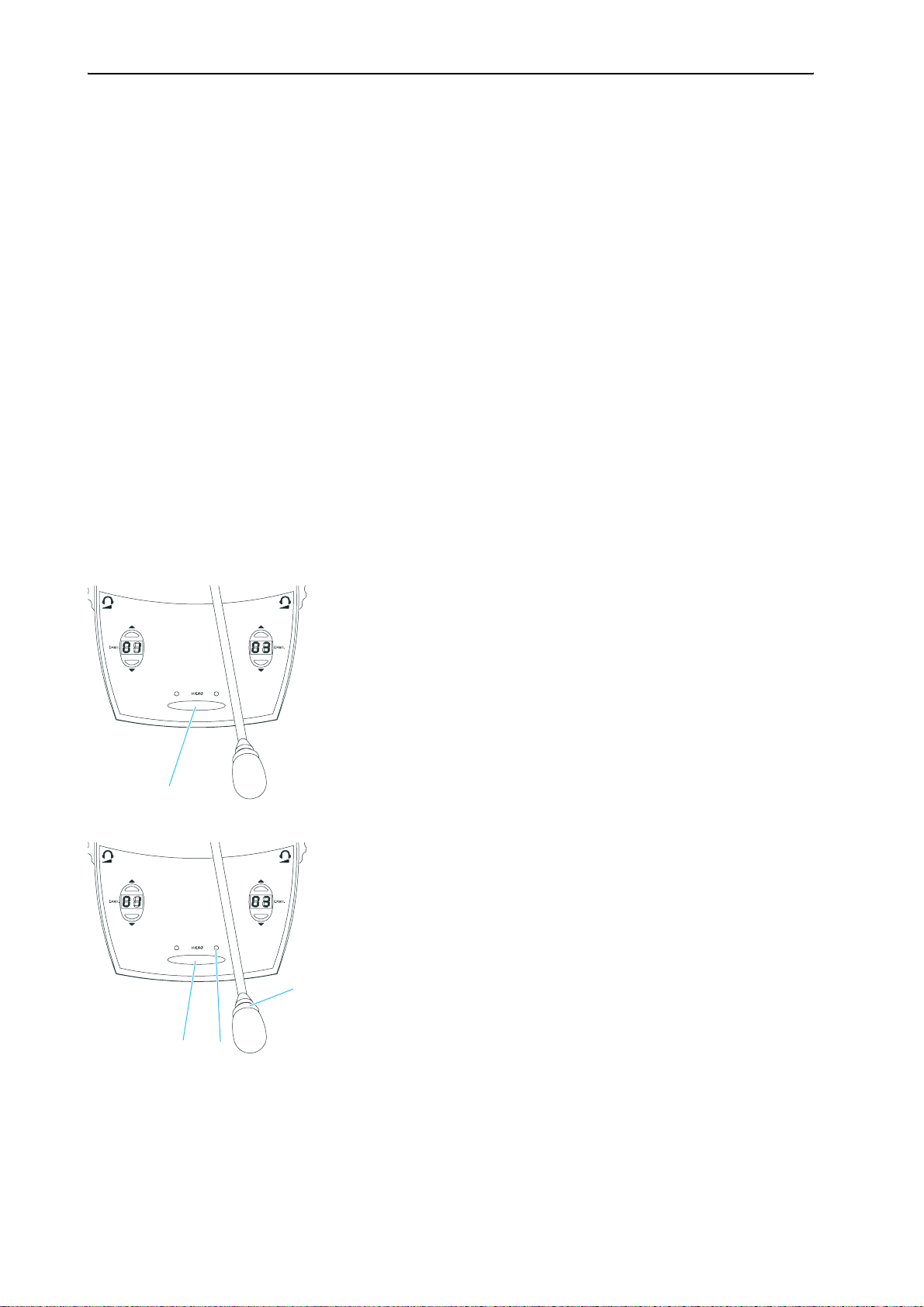
SDC 8000 DC conference unit
The components of the SDC 8000 system in detail
22
IN socket (RJ 45)
OUT socket (RJ 45)
Headphone socket (3.5 mm jack)
Loudspeaker
Red signal light ring
Microphone
“Microphone active” LED
MICRO key
“Request to speak” LED
Channel display with “CHAN. 왖” and “CHAN. 왔” channel selection keys
Headphone volume control for headphone socket
Headphone socket (3.5 mm jack)
Headphone volume control for headphone socket
22
17
The components of the SDC 8000 system in detail
SDC 8000 CC chairman unit
IN socket (RJ 45)
OUT socket (RJ 45)
Headphone socket (3.5 mm jack)
Loudspeaker
PRIOR. key
Red signal light ring
Microphone
“Microphone active” LED
MICRO key
“Request to speak” LED
NEXT key
Channel display with “CHAN. 왖” and “CHAN. 왔” channel selection keys
Headphone socket (3.5 mm jack)
18
Headphone volume control for headphone sockets and
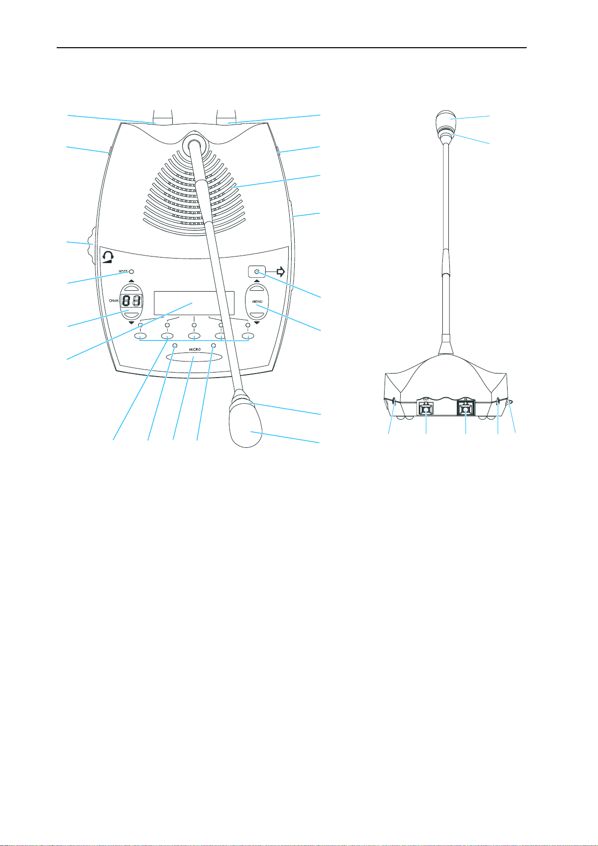
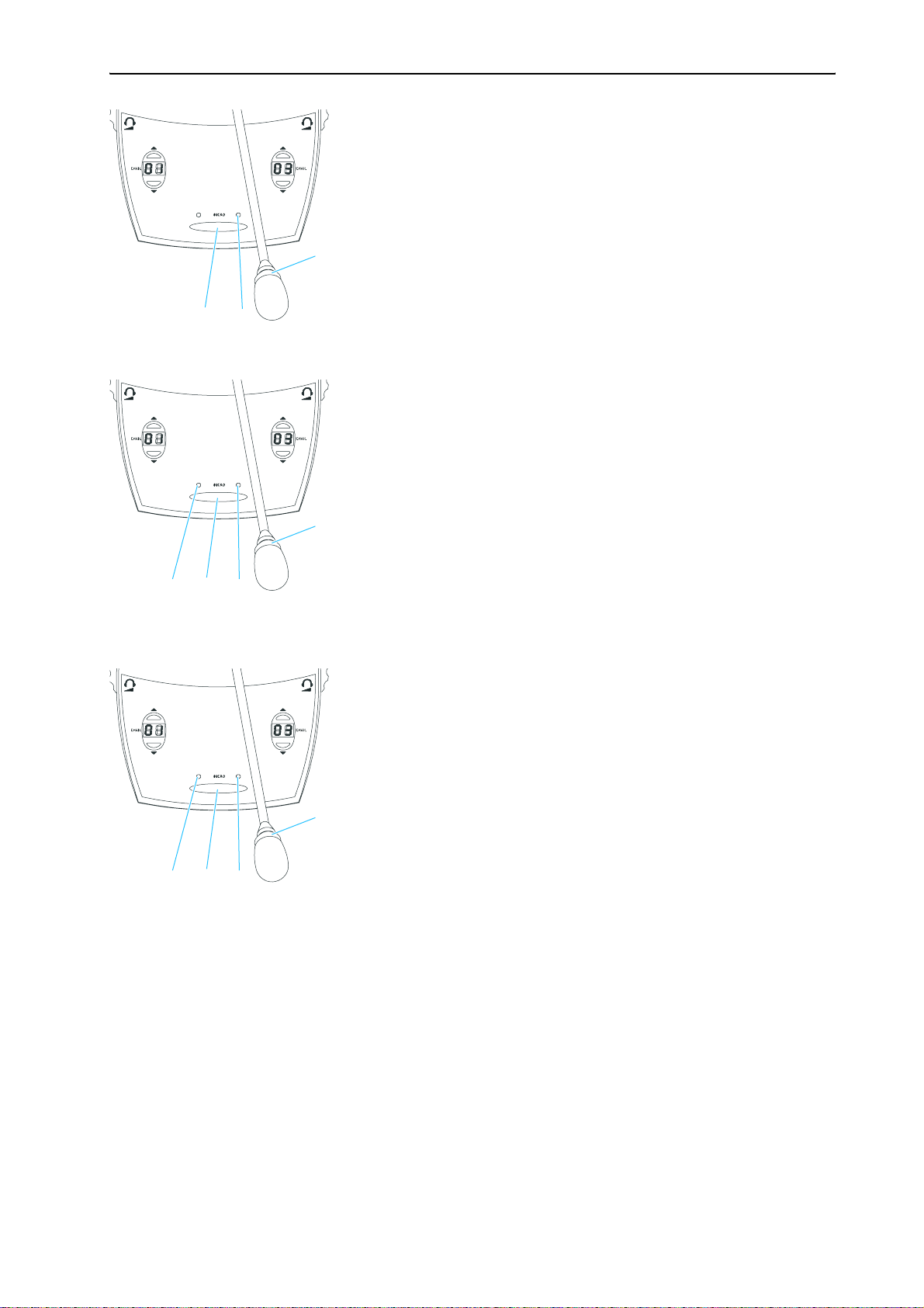
SDC 8000 DV conference unit
The components of the SDC 8000 system in detail
22
IN socket (RJ 45)
OUT socket (RJ 45)
Headphone socket (3.5 mm jack)
Loudspeaker
Chip card slot
“Chip card” LED
“MENU 왖” and “MENU 왔” menu selection keys
Red signal light ring
Microphone
“Microphone active” LED
MICRO key
“Request to speak” LED
Voting keys
Dot matrix display
Channel display with
“CHAN. 왖” and “CHAN. 왔” channel selection keys
VOTE LED
Headphone volume control for
headphone sockets and
Headphone socket (3.5 mm jack)
22
19
The components of the SDC 8000 system in detail
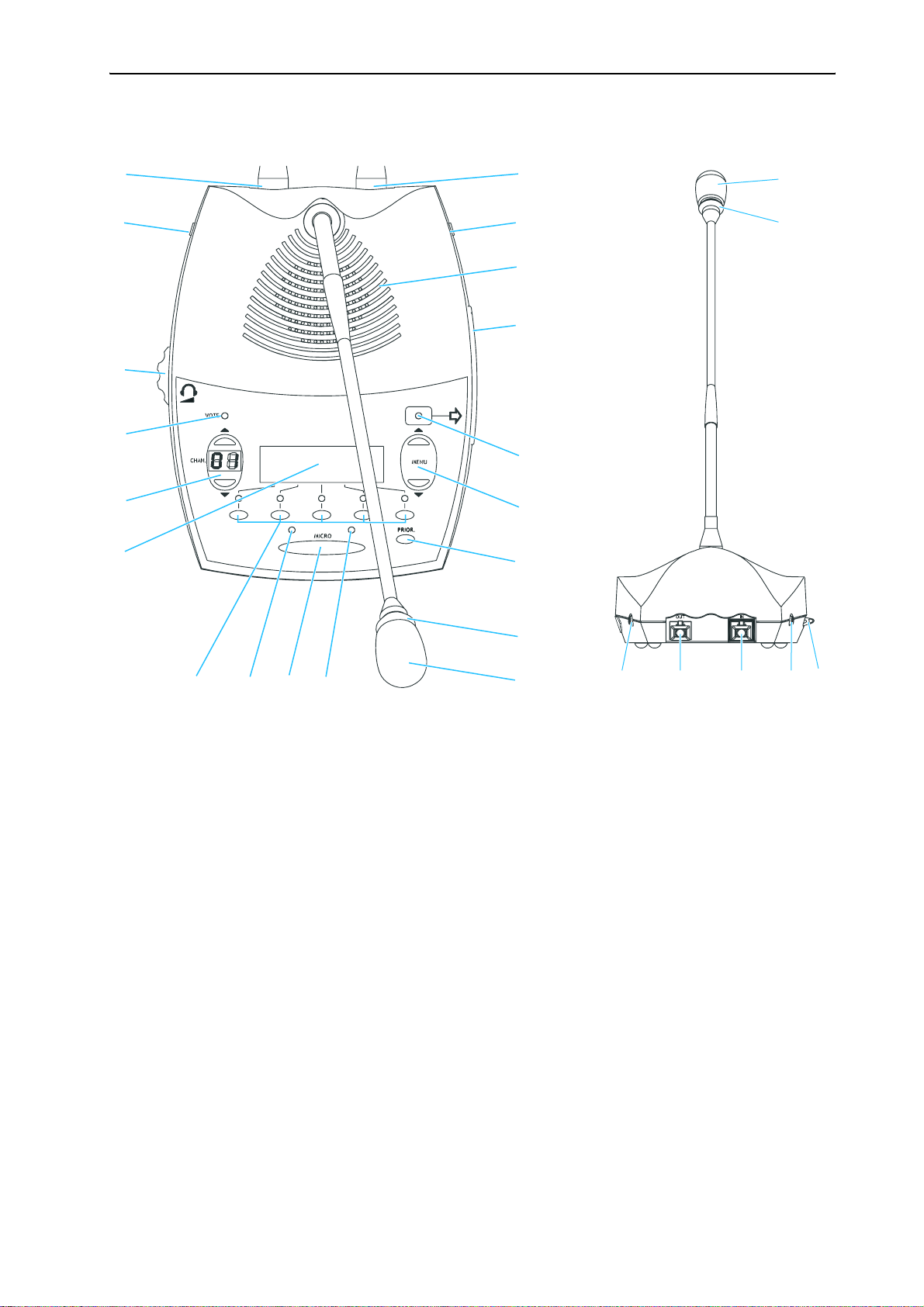
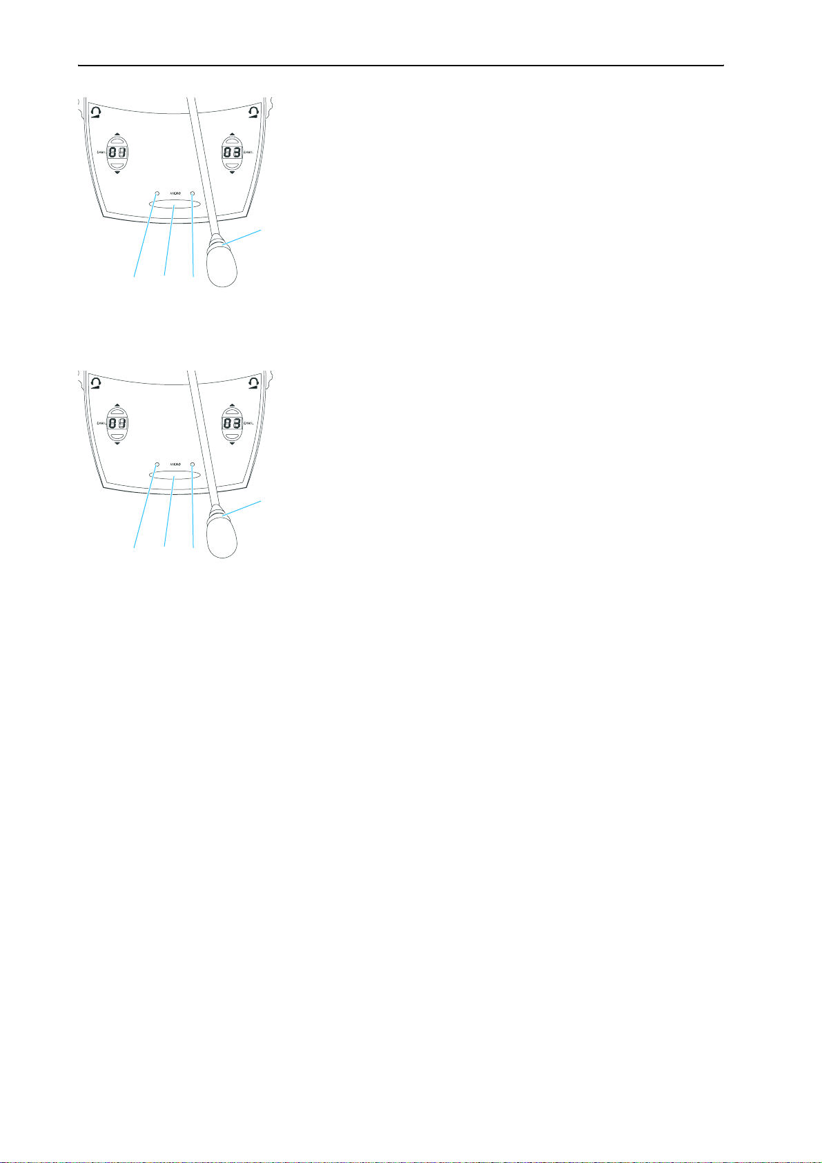
SDC 8000 CV chairman unit
22
IN socket (RJ 45)
OUT socket (RJ 45)
Headphone socket (3.5 mm jack)
Loudspeaker
Chip card slot
“Chip card” LED
“MENU 왖” and “MENU 왔” menu selection keys
PRIOR. key
Red signal light ring
Microphone
“Microphone active” LED
MICRO key
“Request to speak” LED
Voting keys
Dot matrix display
Channel display with
“CHAN. 왖” and “CHAN. 왔” channel selection keys
VOTE LED
Headphone volume control
for headphone sockets and
Headphone socket (3.5 mm jack)
22
20
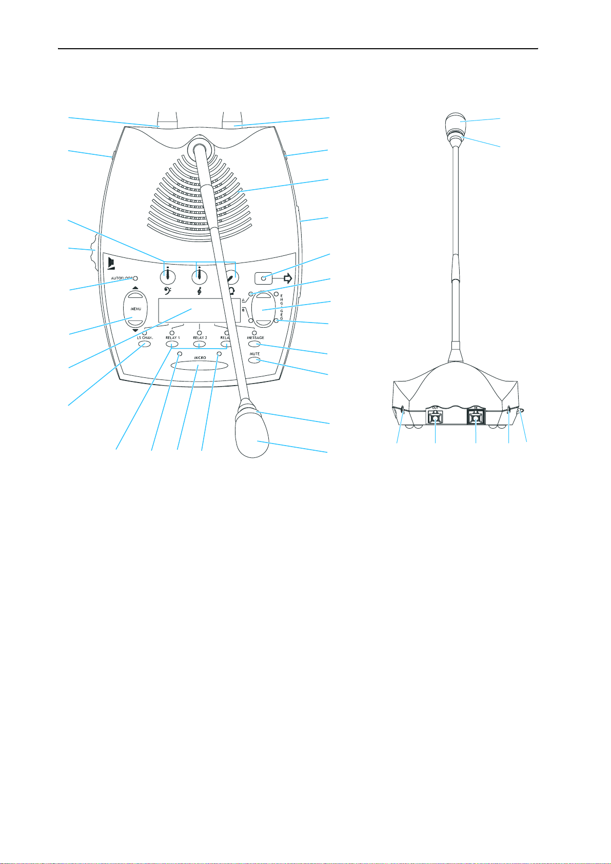
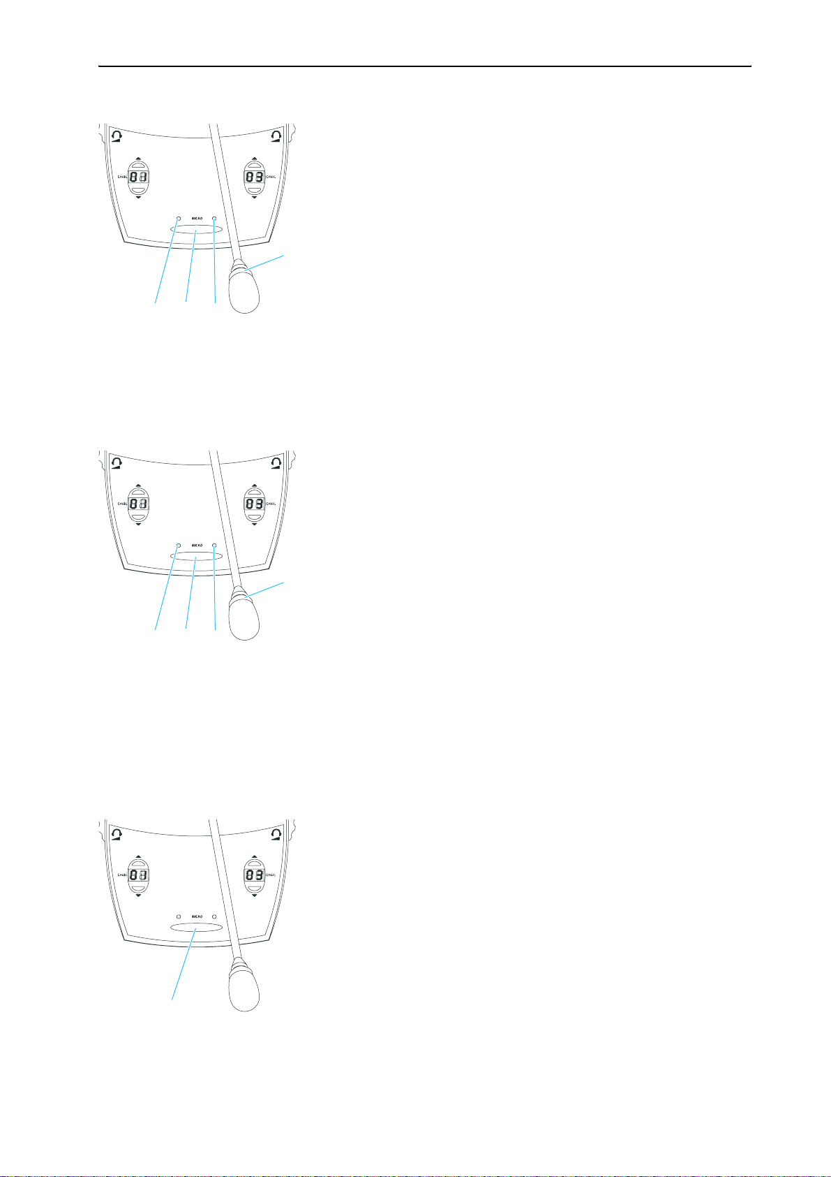
SDC 8000 ID interpreter console
The components of the SDC 8000 system in detail
22
IN socket (RJ 45)
OUT socket (RJ 45)
Headphone socket (3.5 mm jack)
Loudspeaker
Chip card slot
“Chip card” LED
“Channel” LEDs “A” and “B“
Channel keys “A” and “B“
ENGAGED LEDs “A” and “B“
MESSAGE key
MUTE key
Red signal light ring
Microphone
“Microphone active” LED
MICRO key
“Request to speak” LED
RELAY 1 to RELAY 3 keys
LS CHAN. key
Dot matrix display
“MENU 왖” and “MENU 왔” menu selection keys
AUTOFLOOR LED
Loudspeaker volume control
Tone controls (volume, middle and treble)
for headphone sockets and
Headphone socket (3.5 mm jack)
22
21
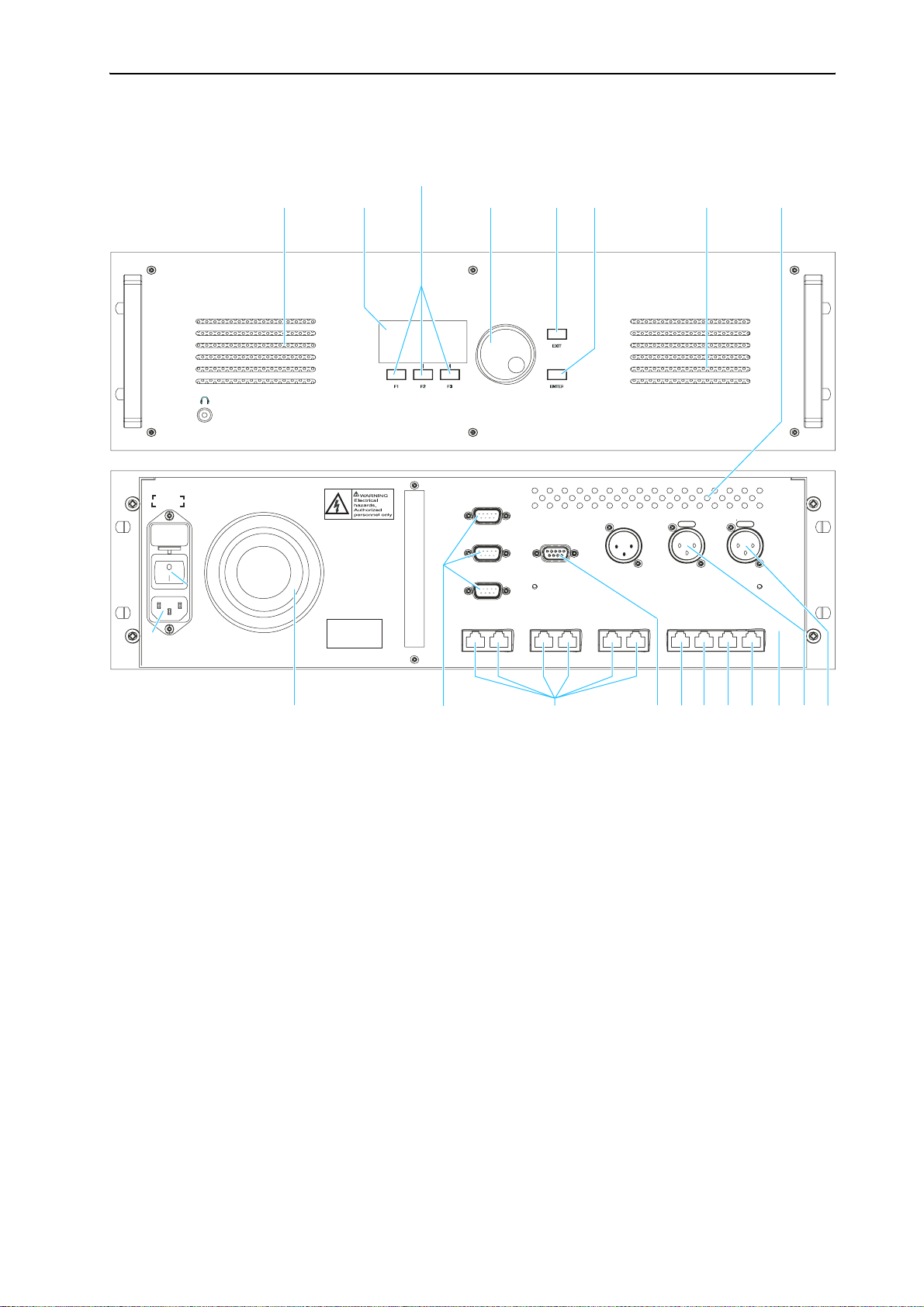
The components of the SDC 8000 system in detail
The SDC 8000 CU central unit
FUSE
(5x20 mm)
3.15A(T)
PORT 2
100-240 AC
50-60 Hz
CE
PORT 6 PORT 5
COM 1
COM 2
COM 3
AUX OUT 2 - 3 - 4 - 5
PORT 4 PORT 3
AUX OUT 1 AUX IN 2 AUX IN 1
DATA
SLAVE
PORT 2 PORT 1
OUT
OUT
SLAVEINMASTER
OUT
Headphone socket (3.5 mm jack)
Display
F1 to F3 menu keys
Jog wheel for selecting the menus
EXIT key
ENTER key
Air vents
AUX IN 1 audio input (XLR-3F)
AUX IN 2 audio input (XLR-3F)
AUX OUT 1 audio output (XLR-3M)
MASTER OUT socket (RJ 45)
SLAVE IN socket (RJ 45)
SLAVE OUT socket (RJ 45)
DATA OUT socket (RJ 45)
AUX OUT 2-3-4-5 audio outputs
(9-pole sub-D socket)
PORT 1 to PORT 6 sockets (RJ 45)
for connecting cable strings
COM 1 to COM 3 serial interfaces
Fan for integrated power supply
POWER switch
Socket for mains cable
22
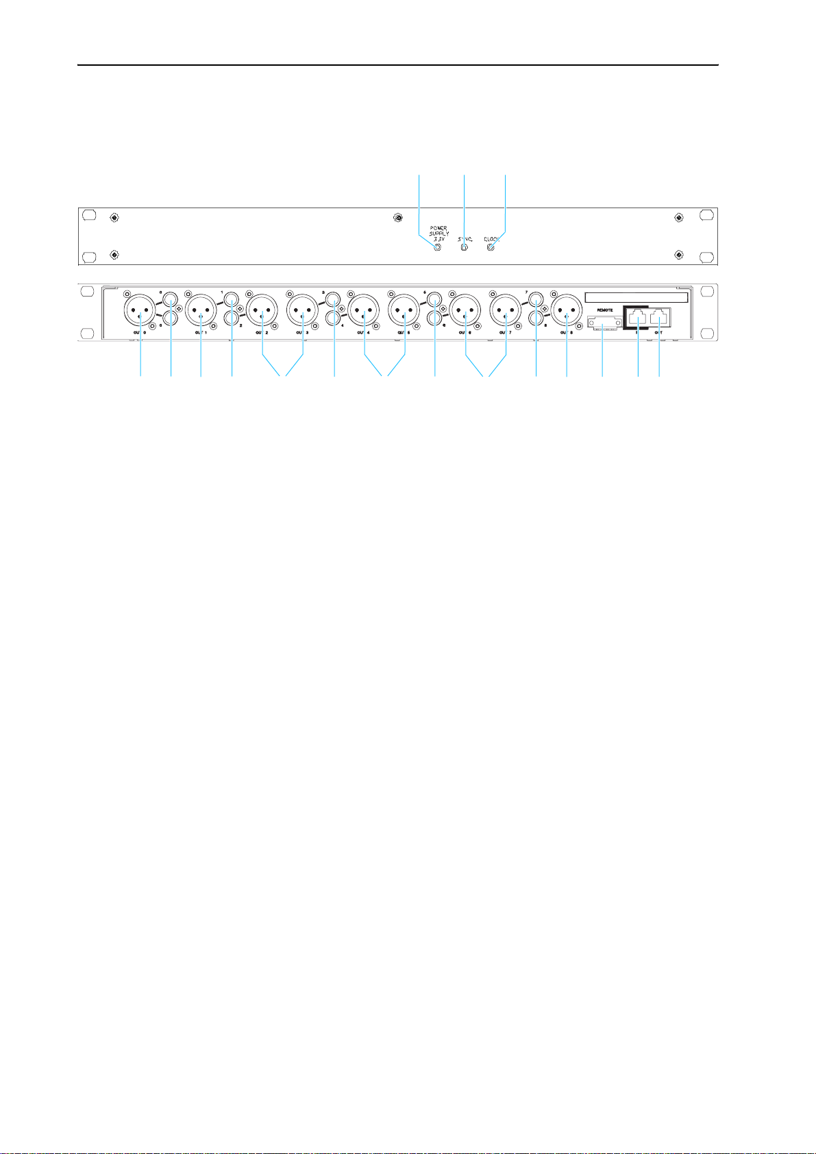
The components of the SDC 8000 system in detail
The SDC 8000 AO analog output unit (optional)
POWER SUPPLY LED (lights up, if power is supplied to the SDC 8000 AO)
SYNC. LED (lights up, if the data exchange between the central unit and
the SDC 8000 AO functions correctly)
FLOOR LED (lights up, if the floor channel is being used)
DIGITAL BUS OUT socket (RJ 45) for connecting an additional analog
output unit
DIGITAL BUS IN socket (RJ 45) for connection of the central unit
Phoenix connector (e.g. for turning on/off a recording unit via a
voltage-free contact)
Phono socket (unbalanced), 10x
XLR-3M audio output (transformer balanced), 9x
23
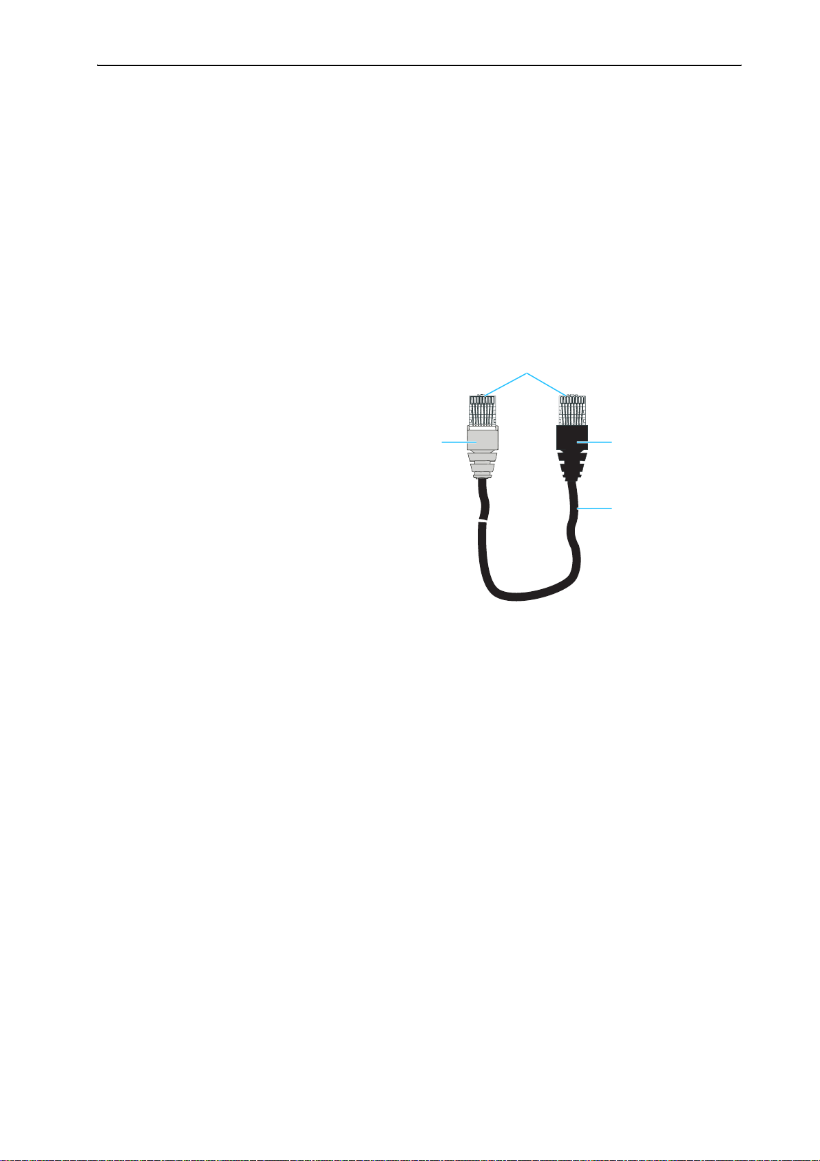
The components of the SDC 8000 system in detail
The system cables
The system cables required for your planned conference and
interpretation system must be ordered separately. The system cables are
available with lengths of 2 m, 3 m, 5 m, 10 m, 20 m and 50 m.
Via the system cables, you can:
y interconnect the conference and interpreter consoles,
y interconnect up to 10 central units for setting up a large conference and
interpretation system,
y connect an SDC 8000 AO analog output unit to the central unit,
y connect cable strings to the central unit.
The system cables must meet the following specifications:
Shielded RJ 45 modular plug, cat 5(e)
Black cable booth with clip protector
Round STP cable, cat 5(e), 24AWG
Grey cable booth with clip protector
24
Operating the components of the SDC 8000 system
Operating the components of the
SDC 8000 system
Depending on the type of delegate unit, conference participants can:
y listen, take the floor or make a request to speak,
y receive simultaneous interpretation,
y participate in voting sessions.
In addition to the functions and features of the delegate units, the
chairman unit allows to:
y start a voting session,
y turn off all active conference consoles (priority function).
The interpreter consoles are exclusively used by the interpreters.
The central unit is operated by the conference manager – either directly or
via an optional PC with software control.
Operating the delegate units
Taking the floor / Making a request to speak
In order to take the floor or make a request to speak, you have to press the
MICRO key . Depending on the conference mode chosen, you can either
take the floor immediately or you have to wait until your microphone is
turned on.
1. In “Direct Access” mode:
왘 Press the MICRO key .
If the speaker limit has not yet been reached, you can take the floor
immediately. The red signal light ring and the “Microphone active”
LED on your console light up permanently, indicating that you can
now take the floor.
If the speaker limit has been reached, you have to wait until one of the
current speakers has finished speaking and passes on the “speaking
right”. You then have to press the MICRO key again.
2. In “Fifo” mode:
In this mode, the speaker limit is 1.
25
Operating the components of the SDC 8000 system
왘 Press the MICRO key .
Pressing the MICRO key on your console will automatically turn off the
microphone of the previous speaker (“first-in-first-out” principle). The
red signal light ring and the “Microphone active” LED on your
console light up permanently, indicating that you can now take the
floor.
Note!
One delegate unit and the chairman unit can be simultaneously active.
3. In “Group 1” mode:
In this mode, the speaker limit is 1.
왘 Press the MICRO key .
If no other participant is currently speaking, you can take the floor
immediately. The red signal light ring and the “Microphone active”
LED on your console light up permanently, indicating that you can
now take the floor.
If the speaker limit has been reached, you will join the waiting list and
the green “Request to speak” LED on your console starts flashing. As
soon as the active microphone is turned off, the microphone of the first
participant from the request-to-speak list is turned on, and so on.
When it is your turn to speak, the red signal light ring and the
“Microphone active” LED on your console light up permanently.
4. In “Group 2” mode:
In this mode, the speaker limit is 2.
왘 Press the MICRO key .
If the speaker limit has not yet been reached, you can take the floor
immediately. The red signal light ring and the “Microphone active”
LED on your console light up permanently, indicating that you can
now take the floor.
If the speaker limit has been reached, you will join the waiting list and
the green “Request to speak” LED on your console starts flashing. As
soon as one of the active microphones is turned off, the microphone of
the first participant from the request-to-speak list is turned on, and so
on.
When it is your turn to speak, the red signal light ring and the
“Microphone active” LED on your console light up permanently.
5. In “Group 3” mode:
In this mode, the speaker limit is 3.
26
Operating the components of the SDC 8000 system
왘 Press the MICRO key .
If the speaker limit has not yet been reached, you can take the floor
immediately. The red signal light ring and the “Microphone active”
LED on your console light up permanently, indicating that you can
now take the floor.
If the speaker limit has been reached, you will join the waiting list and
the green “Request to speak” LED on your console starts flashing. As
soon as one of the active microphones is turned off, the microphone of
the first participant from the request-to-speak list is turned on, and so
on.
When it is your turn to speak, the red signal light ring and the
“Microphone active” LED on your console light up permanently.
6. In “Group 4” mode:
n this mode, the speaker limit is 4.
왘 Press the MICRO key .
If the speaker limit has not yet been reached, you can take the floor
immediately. The red signal light ring and the “Microphone active”
LED on your console light up permanently, indicating that you can
now take the floor.
If the speaker limit has been reached, you will join the waiting list and
the green “Request to speak” LED on your console starts flashing. As
soon as one of the active microphones is turned off, the microphone of
the first participant from the request-to-speak list is turned on, and so
on.
When it is your turn to speak, the red signal light ring and the
“Microphone active” LED on your console light up permanently.
7. In “No request” mode:
For this mode to function, the SDC 8000 system must be PC controlled.
In “No request” mode, you have to “apply” for a comment and wait until
the conference manager turns on your microphone. The conference
manager has total control of the microphones.
Note!
You cannot “apply” for a comment by pressing the MICRO key .
왘 Signal your intention to take the floor e.g. by raising your hand or
giving another sign.
The conference manager can either assign you the “speaking right” by
turning on your microphone or ignore your request to speak.
When the conference manager turns on you microphone, the red signal
light ring and the “Microphone active” LED on your console light
up permanently. When the conference manager withdraws the
“speaking right” from you, the red signal light ring and the
“Microphone active” LED on your console go off.
27
Operating the components of the SDC 8000 system
8. In “With request” mode:
For this mode to function, the SDC 8000 system must be PC controlled.
In “With request” mode, you have to “apply” for a comment and wait until
the conference manager turns on your microphone.
왘 Press the MICRO key to “apply” for a comment.
The green “Request to speak” LED on your console starts flashing.
The conference manager can either assign you the “speaking right” by
turning on your microphone or ignore your request to speak.
When the conference manager turns on your microphone, the red
signal light ring and the “Microphone active” LED on your console
light up permanently and the green “Request to speak” LED goes off.
Note!
You can cancel your request to speak by pressing the MICRO key once
more.
9. In “With Req. No clear” mode:
For this mode to function, the SDC 8000 system must be PC controlled.
In “With Req. No clear” mode, you have to “apply” for a comment and wait
until the conference manager turns on your microphone.
왘 Press the MICRO key to “apply” for a comment.
The green “Request to speak” LED on your console starts flashing.
The conference manager can either assign you the “speaking right” by
turning on your microphone or ignore your request to speak.
When the conference manager turns on your microphone, the red
signal light ring and the “Microphone active” LED on your console
light up permanently and the green “Request to speak” LED goes off.
Note!
You cannot cancel your request to speak by pressing the MICRO key
once more!
Turning off the microphone / Cancelling a request to speak
To turn off the microphone when you have finished speaking or to cancel
a request to speak:
왘 Press the MICRO key once more.
The red signal light ring and the “Microphone active” LED on your
console go off.
28
Operating the components of the SDC 8000 system
Adjusting the volume of the headphones connected to a conference console
To adjust the volume of the headphones connected to your conference
console:
왘 Connect Sennheiser mono headphones to the 3.5 mm jack socket (
22
and/or ).
왘 First, use the headphone volume control ( and/or ) to reduce the
headphone volume to the minimum.
왘 Put on the headphones and slowly set the volume to a medium level.
Warning!
When people use headphones, they tend to choose a higher volume
than with loudspeakers. Listening at high volume levels for long
periods can lead to permanent hearing defects. Please protect your
hearing, Sennheiser headphones have an excellent sound quality even
at low volumes.
Selecting an interpretation channel
If your console is equipped with channel selection keys (SDC 8000 DC,
SDC 8000 CC, SDC 8000 DV and SDC 8000 CV), you can choose between the
floor channel and the offered interpretation channels.
To select an interpretation channel:
왘 Connect Sennheiser mono headphones to your conference console.
왘 Press the “CHAN. 왖” or “CHAN. 왔” channel selection key .
The selected interpretation channel is output via your headphones.
Mic N.: 900
VOTE 1 OF 3
YES ABS NO
Mic N.: 900
VOTE 1 OF 5
12345
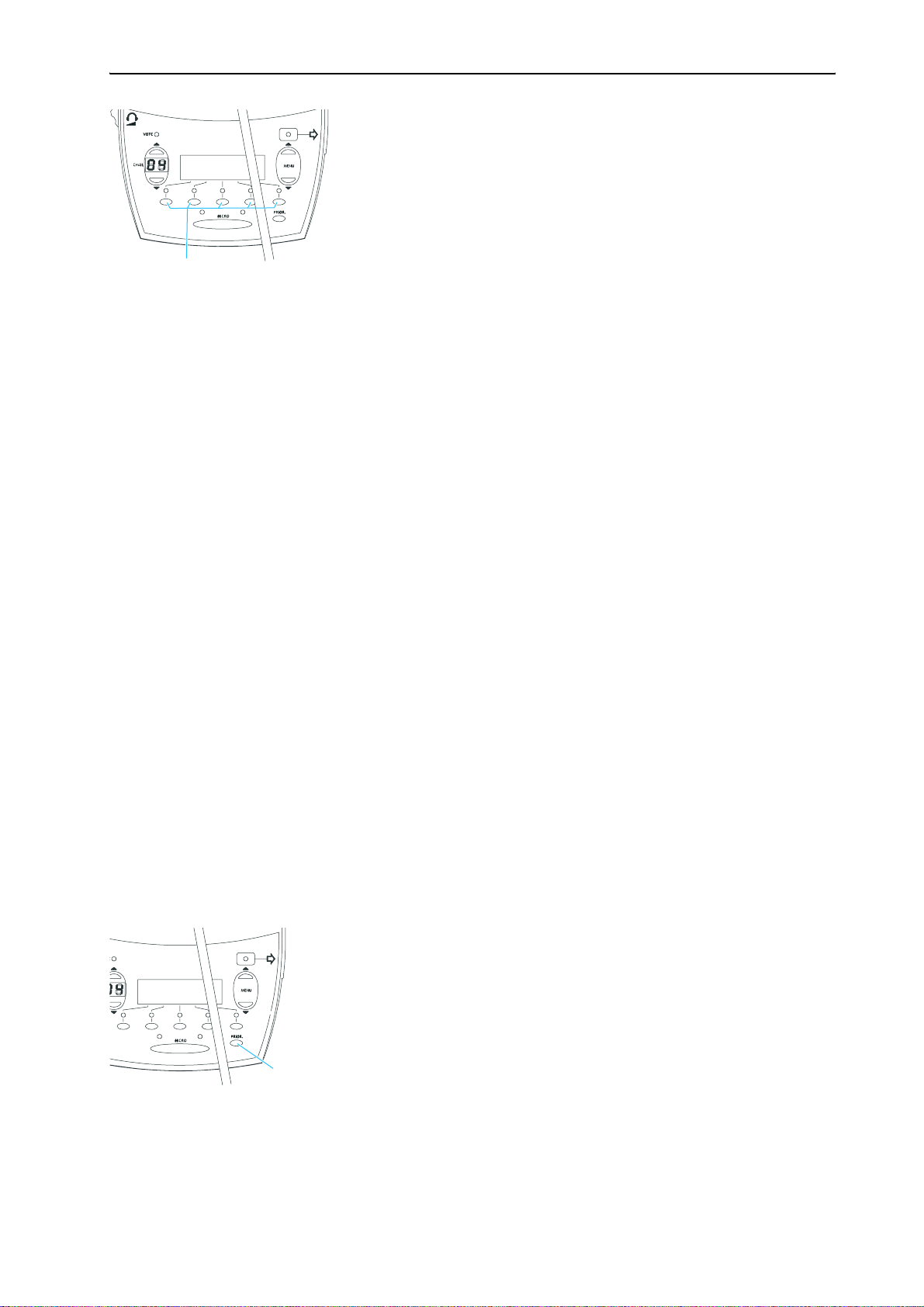
Voting
If your console is equipped with the voting function (only SDC 8000 DV and
SDC 8000 CV), you can participate in voting sessions. Please note that
voting sessions can only be started via the SDC 8000 CV chairman unit.
There are two voting modes (“Vote 1 of 3” and “Vote 1 of 5”) which offer
different voting options (depending on the voting mode chosen, your
display looks like one of the displays shown on the left).
In the “Vote 1 of 3” mode, you can vote “YES” or “NO” or abstain (“ABS”);
in the “Vote 1 of 5” mode, you have the choice of five options (1 to 5):
29
Operating the components of the SDC 8000 system
왘 To cast your vote, press the corresponding key below the display.
Your vote is counted. After the voting session, the result of the vote is
shown on the displays of the consoles.
Using the chip card slot of a conference console
If the conference consoles feature a chip card slot and if your system is PC
controlled, you can:
y make sure that only authorized delegates can participate in voting
sessions.
y take roll-call votes, i.e. you can see the name of each conference
participant and his or her voting position.
Operating the VIP units
VIP units are special delegate units which have the “rights” of a chairman
unit.
y With a VIP unit, you can take the floor at any time, regardless of the
conference mode and without first having to be assigned the “speaking
right”.
y If the chairperson presses the PRIOR. key, all active conference consoles
– except for the VIP units – are turned off. The chairperson cannot
withdraw the “speaking right” from you.
y The VIP units are operated in the same way as the elegate units.
Note:
In order to be able to configure VIP units, you require the software
control of the conference system.
Operating the chairman unit
Turning all active conference consoles off (priority)
All chairman units are equipped with a priority function, allowing the
chairman to stop a discussion any time. By using this function, all active
conference consoles are turned off.
30
To use the priority function:
왘 Press the PRIOR. key.
All active conference consoles – except for the VIP units – are turned
off.
 Loading...