

Sennheiser HME 46-3PTT-LA, HME 46-3PTT-6, HME 46-ATC, HME 46-3PTT-M, HME 46-31 Service Manual
...
Service manual
Product variants
500857 HME 46-3
500467 HME 46-3-6
500874 HME 46-3PTT-M
500468 HME 46-3PTT-6
500469 HME 46-3PTT-L
502172 HME 46-3PTT-LA
500851 HME 46-ATC
502484 HME 46-31
500849 HMD 46-3
500466 HMD 46-3-6
500873 HMD 46-3PTT-M
502483 HMD 46-31
502594 HMD 46-3(5)
Cable variants
500836 -6
502360 -7
502365 -L
500844 -PTT-6
502418 -PTT-6-1
500845 -PTT-L
502187 -PTT-LA
500930 -D-3PTT-M
500931 -E-3PTT-M
Revision
02/2008
Air Traffic Control
HME 46-3
HMD 46-3
SA 070401
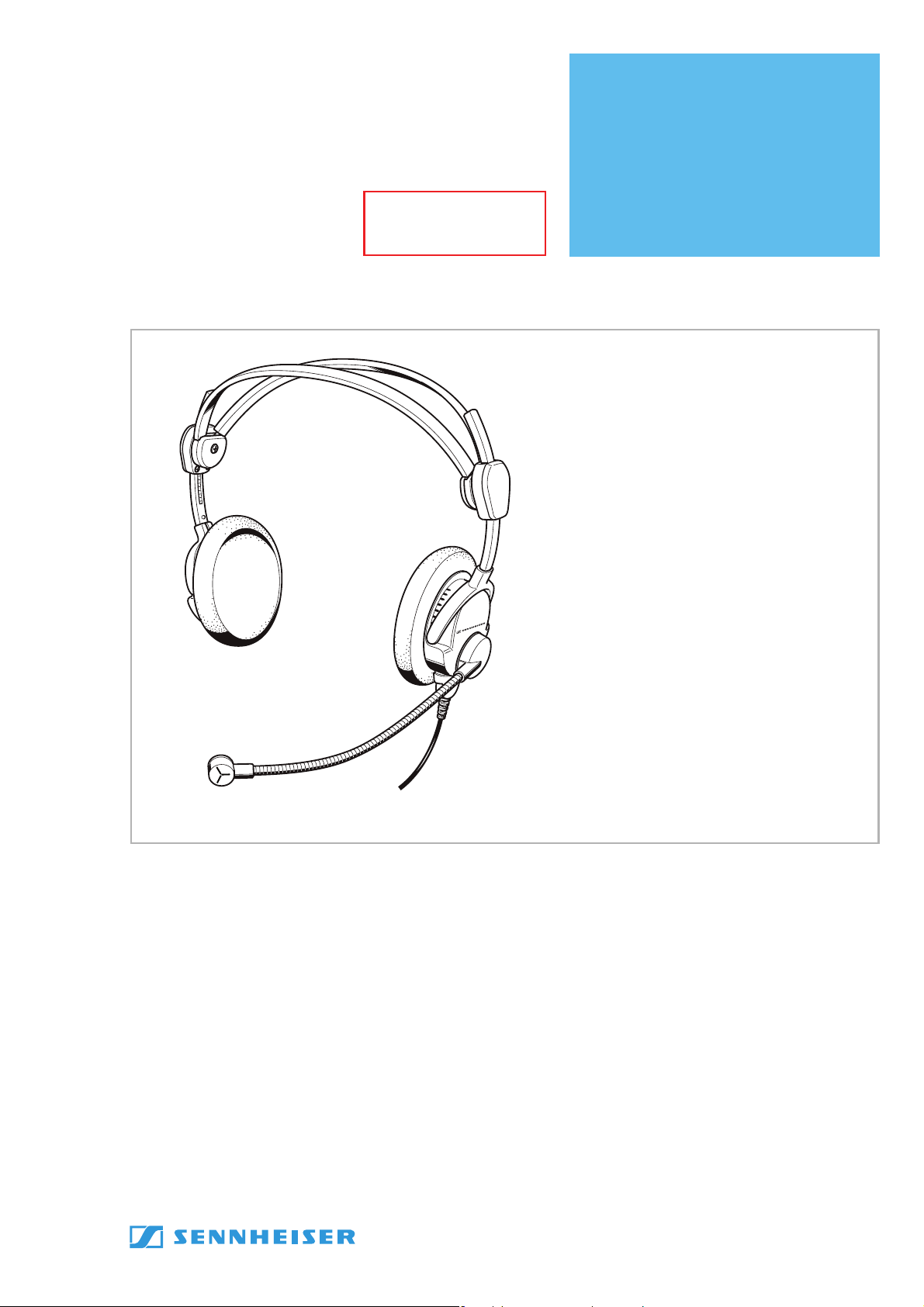
Short description
This headset features dynamic, open headphones. The noise-compensating
microphone ensures excellent speech transmission even in noisy
environments. Designed for air traffic control, intercom systems and other
communication purposes.
Features
• ActiveGard™ (not HME 46-31 and HMD 46-31)
• “Flip-away“ earcup
• Automatic two-piece headband
• Flexible microphone boom can be worn on either left or right-hand side
• Single-sided cable
• Comfortable wearing earpads
• PTT button integrated in the cable (HME/HMD 46-3PTT-x only)
Subject to alterations
Sennheiser electronic GmbH & Co. KG • 30900 Wedemark, Germany
Phone: +49 (5130) 600 0 • Fax: +49 (5130) 600 300 1/25

Safety requirements
Observe safety regulations.
Observe ESD instructions while handling electrostatically endangered components.
Only skilled perso
approved components according to the current spare parts list are allowed.
For safety and certification reasons it is forbidden to alt
authorization. Otherwise, the person who has
consequential damage.
repairs/exchanges The following instructions for overhaul and testing must
In case of unusual problems please contact yo
ns are allowed to alter and repa
ir. For repairs and exchanges only
altered the product is liable for any
ur Sennheiser distributor.
er the product without
be followed.
HME 46-3, HMD 46-3
2/25 02/2008

Contents
1 Outline dimension ..........................................................................................5
2 Technical Data.................................................................................................6
2.1 Headphones........................................................................................................... 6
2.2 Microphone of HMD 46-3.................................................................................... 6
2.3 Microphone of HMD 46-3(5) .............................................................................. 6
2.4 Microphone of HME 46-3 (with preamplifier) ................................................ 6
2.5 General data .......................................................................................................... 6
3 Disassembly ....................................................................................................7
3.1 Removal of the cable ........................................................................................... 7
3.2 Disassembly of the cap........................................................................................ 7
3.3 Disassembly of the cable .................................................................................... 7
3.4 Disassembly of the microphone arm ................................................................ 8
4 Assembly .........................................................................................................9
4.1 Assembly of the cap............................................................................................. 9
4.2 Assembly of the -PTT-x cable............................................................................. 9
4.3 Assembly of the cable to the headset............................................................10
4.4 Assembly of the microphone arm ...................................................................10
5 Testing and fault isolation......................................................................... 11
5.1 Tools and test equipment .................................................................................11
5.2 Operational test of the audio system............................................................. 11
5.2.1 Audio testing the headset with cable ............................................................11
5.2.2 Operational testing of the pre-polarized m
at the headset with cable (HME 46-3-x only) .............................................. 11
5.2.3 Testing of the dynamic microphone
a
t the headset with cable (HMD 46-3-x only)..............................................12
5.2.4 Operational testing of the headset cables .................................................... 12
Audio testing of the headset without cable .................................................12
5.2.5
5.2.6 Testing of the ActiveGard™ of the PCB (not HMD/E 46-31)...................... 13
icrophone
6 Wiring diagrams .......................................................................................... 15
6.1 Wiring diagram for cable -E-3PTT-M, -D-3PTT-M.........................................15
6.2 Wiring diagram for cable -PTT-L...................................................................... 16
6.3 Wiring diagram for cable -PTT-6..................................................................... 17
6.4 Wiring diagram for cable -PTT-LA................................................................... 18
6.5 Printed circuit boards ........................................................................................ 19
6.6 Block diagram......................................................................................................20
7 Exploded views with spare part lists........................................................ 21
7.1 Exploded view HME 46-3 / HMD 46-3 ............................................................ 21
7.2 Spare part list for HME 46................................................................................. 22
7.3 Spare part list for HMD 46 ................................................................................ 22
7.4 Exploded view of the system module ............................................................ 23
7.5 Spare part list of the system module
not microphone side (525764) .......................................................................23
7.6 S
7.7 E
7.8 Spare part list of the cap, microphone side...................................................24
7.9 Exploded view cable -PTT-x .............................................................................. 25
7.10 Spare part list for cable -PTT-x ........................................................................ 25
pare part list of the system module
microphone side (525763)............................................................................... 23
xploded view of the cap, microphone side ..................................................24
HME 46-3, HMD 46-3
02/2008 3/25
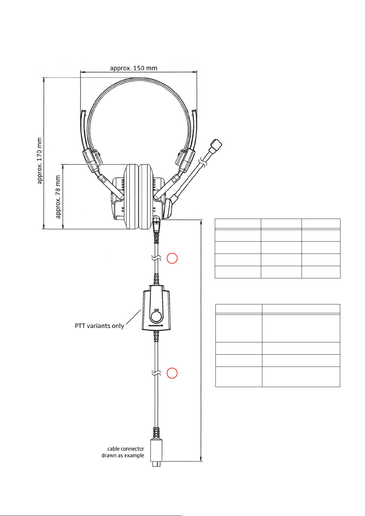
1 Outline dimension
1
2
Cable type Complete cable length
-PTT-6,
-PTT-6-1,
-PTT-L
1.85 m
-PTT-LA
2.30 m
-E/D-3PTT-M
2.45 m
-7,
-ATC / -L
2.00 m
Cable type
Length of
Length of
-E/D-3PTT-M 0.80 m
1.60 m
-PTT-LA 0.50 m
1.75 m
-PTT-L, -PTT-6 1.50 m
0.30 m
-PTT-6-1 0.80 m
1.00 m
HME 46-3, HMD 46-3
02/2008 5/25

2 Technical Data
2.1 Headphones
Transducer principle_______________________ dynamic, open
Ear coupling_____________________________ supra-aural
Frequency response _______________________ 20 to 14.000 Hz
Impedance _____________________________300 ohms per system
Sensitivity
HMD/E 46-3 _______________________ 95 dB/SPL at 1 kHz, 1 mW mono
83 dB/SPL at 1 kHz, 1 V
HMD/E 46-31 ______________________ 95 dB/SPL at 1 kHz, 1 mW mono
103 dB/SPL at 1 kHz, 1 V
THD
HMD/E 46-3 _______________________ < 1 % at 95 dB SPL (350 to 3.000 Hz)
HMD/E 46-31
Contact pressure _________________________aprx. 3.0 N
2.2 Microphone of HMD 46-3
Type _______________________________ MD 46-413
Transducer principle
Frequency response
Output voltage
Impedance
____________________________ 200 ohms
______________________< 1 % at 110 dB SPL (350 to 3.000 Hz)
_____________________ dynamic, noise compensating
______________________ 100 to 12.000 Hz
_________________________ 0.5 mV/Pa
2.3 Microphone of HMD 46-3(5)
Type _______________________________ MD 46-413_5 ohms
Transducer principle
Frequency response
Output voltage
Impedance
____________________________ 5 ohms
_____________________ dynamic, noise compensating
______________________ 100 to 12.000 Hz
_________________________ 0.125 mV/Pa
2.4 Microphone of HME 46-3 (with preamplifier)
Type _______________________________ MKE 46
Transducer principle
Frequency response
Output voltage
HME 46-3, -3-6, -3PTT-M,
-3PTT-6, -3PTT-L, HME 46-31
HME 46-3PTT-LA, -ATC adjustable from 17 to 215 mV/Pa,
Terminating impedance
Supply voltage
_____________________ pre-polarized condenser microphone, noise compensating
______________________ 350 to 6.000 Hz
__________ adjustable from 17 to 100 mV/Pa,
80 mV/Pa (factory pre-set) ≅ 800 mV at
152 mV/Pa (factory pre-set) ≅ 1520
___________________ 150 to 2.200 ohms
_________________________ 8 to 16 V DC
114 dB SPL
mV at
114 dB SPL
2.5 General data
Ambient temperature
operating mode ___________________ -15°C to 55°C
stocking
Weight, without cable
6/25 02/2008
_________________________ -55°C to 70°C
____________________ aprx. 150 g
HME 46-3, HMD 46-3

3 Disassembly
3.1 Removal of the cable
Reference:
• see “Exploded view HME 46-3 / HMD 46-3”, page 21.
1. Loosen the screws of the cable.
2. Remove the cable from the cable holder (110).
3.2 Disassembly of the cap
Reference: see “Exploded view HME 46-3 / HMD 46-3”, page 21.
1. Remove the earpad (90) from the relevant cap (20 or -25).
2. Lift the sides of the discs (80), now the screws (70) are visible
caps (20 or -25) completely if necessary.
3. Remove the screws (70).
4. Pull out the the resonator (60) with capsule.
5. Remove the center (50).
6. Remove the felt plate (40).
7. Unsolder the leads of the cable (TP1 to TP4) of t
see “Printed circuit boards”, page 19.
8. Unsolder the leads from the capsules (TP8, TP9), see “Printed circuit boards”, page 19 or see “Exploded view of the system module”, page 23.
9. Unsolder the cable from the microphone arm (100 or -105) (TP5 to TP7)*.
10.
Remove the cable holder (110) from the cap (20)*.
11. Remove the cap (20 or -25) from the split headband (10).
he split headband (10) from the PCB,
or remove the discs (80) from the
3.3 Disassembly of the cable
Reference: see “Exploded view cable -PTT-x”, page 25.
1. Remove the four screws (40) of the housing (10).
2. Open the housing (10, 30).
3. Remove the inserts (50).
4. Take out the PCB (60) and the cables (90, 100) of the
5. Desolder the cables (90, 100) from the PCB (60).
housing (10).
* Only microphone side.
HME 46-3, HMD 46-3
02/2008 7/25
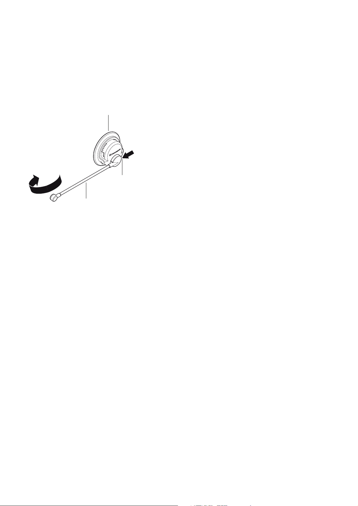
3.4 Disassembly of the microphone arm
100
20
10 (of the cap module)
Reference: see “Exploded view HME 46-3 / HMD 46-3”, page 21 or see “Exploded view of the cap, microphone
side”, page 24.
1. Rotate the microphone arm (100 or
-105) to the side position if necessary
(see figure below).
2. Screw the threaded pin (10 of the cap module) completely into the microphone arm fixing
3. Disassemble the microphone arm (100 or -105) from the cap (20) by
moving the microphone down
towards to the other cap (-25) of the headset .
.
HME 46-3, HMD 46-3
8/25 02/2008

4 Assembly
4.1 Assembly of the cap
Reference:
• see “Exploded view HME 46-3 / HMD 46-3”, page 21.
1. Attach the relevant cap (20 or -25) to the headband (10).
2. Solder the relevant leads of the split headband cable to the PCBs (TP1 to TP4), see “Printed circuit boards”, page 19 and see “Block diagram”, page 20.
3. Solder the microphone cable (TP5 to TP7) at the microp
and see “Block diagram”, page 20.
4. Put the center (50) over the resonator (60) and solder
(TP8 and TP9) to the PCB , see “Printed circuit boards”, page 19 and see “Block diagram”, page 20.
5. Install the felt plate (40) on the PCBs
6. Turn the center (50) into the cap (20 or -25).
7. Set the capsule with resonator (60)
8. Install the screws (70) with a torque of 25 Ncm
9. Install the label (120) on the cap (-25), if applicable.
10. Install the disc (80) on the resonator (60) if necessary.
11. Install the earpad (90) over the disc (80) on the cap (20 or -25).
(20 of the system module).
into the cap (20 or -25).
±3 Ncm.
4.2 Assembly of the -PTT-x cable
hone arm PCB, see “Printed circuit boards”, page 19
the orange and brown leads at the relevant pins
Reference: see “Exploded view cable -PTT-x”, page 25
1. Solder the cables (90, 100) at the PCB (60), see “Wiring diagrams”, page 15 et sqq.
2. Install the PCB (60) with the cables (90, 100) into the housing (10).
3. Close the housing (10) with the cover (30).
4. Install the inserts (50) at the top of the housing (10).
5. Fasten the screws (40) of the housing (10) with a torque of 25
Ncm ±3 Ncm.
* Only for microphone side.
HME 46-3, HMD 46-3
02/2008 9/25

4.3 Assembly of the cable to the headset
PCB
PCB cable (inside)
20
100
10 (of the cap module)
Reference:
• see “Exploded view HME 46-3 / HMD 46-3”, page 21.
1. Set the connector of the system cable into the cable
2. Fasten the screws of the system cable with a torque of 25 Ncm
holder (110)*.
±3 Ncm.
4.4 Assembly of the microphone arm
Reference: see “Exploded view HME 46-3 / HMD 46-3”, page 21.
1. At the inside of the microphone arm fixing is a latch . Fi
position of the cap (20).
2. Hook
3. Fix the
the microphone arm (100 or -105) into the cap (20).
microphone arm (100 or -105) with the threaded pin (10 of the cap module) to outside.
threaded pin (10 of the cap module) out to exceed in the assembled condition 0.1 to 0.3 mm over the
surface of the microphone arm fixing.
rstly set this latch at the right socket
Turn the
* Only for microphone side.
HME 46-3, HMD 46-3
10/25 02/2008

5 Testing and fault isolation
5.1 Tools and test equipment
Description Specification / Type Source
Power supply U: 0-30V DC adjustable
I: ≥500 mA
Hum: <1%
Sine wave generator AF Level adjustable Commercial
Multimeter U: 0-30V DC
I: ≥50
Resolution ≤ 0.1 V
Oscilloscope - Commercial
Intercom
Audio amplifier
-
Any audio amplifier with
hi
impedance micro
gh
input
0 mA
eff
eff
5.2 Operational test of the audio system
References
• see “Cable connector´s pin alignment”, page 14.
• see “Wiring diagrams”, page 15 et sqq.
• see “Printed circuit boards”, page 19.
Commercial
Commercial
Commercial
Commercial
5.2.1 Audio testing the headset with cable
1. Connect the sine wave generator with the negative and the positive line at the relevant pins of the connector, see “Cable connector´s pin alignment”, page 14 or see “Wiring diagrams”, page 15 et sqq.
2. Set the sine wave generator to 300 mV eff ± 5 mV with a signal of 1
3. A clear signal without any distortion must
be audible in both capsules.
kHz and switch the generator on.
5.2.2 Operational testing of the pre-polarized microphone at the headset with cable (HME 46-3-x only)
A. Audio testing, see “Cable connector´s pin alignment”, page 14 and see “Wiring diagrams”, page 15 et sqq.
1. Connect the headset with the cable
2. Put on the headset, adjust the microphone to the correct position and talk into the microphone.
3. Listen to the audio output signal. No distortion should be
B. Visual testing
1. For detailed visual testing please use the ossiloscope, see “Microphone test setup according to RTCA/DO214”, page 14.
connectors into the intercom.
audible.
HME 46-3, HMD 46-3
02/2008 11/25

5.2.3 Testing of the dynamic microphone at the headset with cable (HMD 46-3-x only)
Reference: See fig. 1 “Operational test of the dynamic microphone” page 13
A. Operational testing
1. Connect the microphone connector of the headset wi
audio amplifier input, see “Cable connector´s pin alignment”, page 14 or see “Wiring diagrams”, page 15
et sqq.
2. Connect the headphone connector of the headset with th
fier output, see “Cable connector´s pin alignment”, page 14 or see “Wiring diagrams”, page 15 et sqq.
3. Connect the oscilloscope into a free amplifier output, see “Operational test of the dynamic m
page 13
4. Speak into the microphone of the headset:
- The speaker´s voice will be audible without any distortion in both
- The amplified audio signal of the speaker´s voic
B. Testing of the capsule via resistor measurement
1. Set the multimeter into resistor measurement mode.
2. Connect the multimeter at the relevant pins of the cable connector, see “Cable connector´s pin alignment”,
page 14 or see “Wiring diagrams”, page 15 et sqq. Result: The multimeter displays 20
correct connection of the cable and the capsule. There is no failure
th the negative and positve line into the
e negative and positve line into the audio ampli-
icrophone”,
capsules of the headset.
e will be displayed via oscilloscope.
0 ohms ± 10 % for
or breaking in the cables.
5.2.4 Operational testing of the headset cables
References
• see “Cable connector´s pin alignment”, page 14.
• see “Wiring diagrams”, page 15 et sqq.
A. Conductivity test:
Set the multimeter into the conductivity mode and check each cable
connector for conductivity.
B. Operational test of the PTT-button:
The contactivity is available when the PTT-button is pressed.
For the following testing procedures disassemblin
g of the headset is necessary.
from the connector to the system
5.2.5 Audio testing of the headset without cable
A. Testing audio via PCB at the PCB socket P1, see “Printed circuit boards”, page 19.
1. Supply 1 kHz signal at the PCB socket P1.
2. In the headphones, the 1 kHz tone must be audible.
B. Testing of the acoustic transducer.
1. Set the sine wave generator to 100 mVeff ± 5 mV with a signal of 1 kH
and TP9 (-), see “Printed circuit boards”, page 19.
2. In the headphones, the 1 kHz tone must be audible.
z to the PCB. Set a signal to TP8 (+)
HME 46-3, HMD 46-3
12/25 02/2008

5.2.6 Testing of the ActiveGard™ of the PCB (not HMD/E 46-31)
Speaker´s voice
Audio amplifier
output
Headphone
connector
input
Microphone
connector
output
Oscilloscope
1. Connect the sine wave generator with the negative and the positive line at TP3 (+) and TP4 (-), see “Printed circuit boards”, page 19.
2. Measure the output signal at TP8 (+) and TP9 (-), see “Printed circuit boards”, page 19.
3. The following table show you the input levels of the signal generator and the c
measurement results:
orresponding
Input signal of 1 kHz
at TP3 (+) and TP4 (-)
Output level at TP8 (+) and TP9 (-):
Audible via loudspeaker
of the PCB
300 mV
±5 mV Output level is reduced about
eff
min. 8 dBV. The PCB with
1 V
±5 mV 30 to 40 mV
eff
loudspeaker works correctly.
Output level at TP8 (+) and TP9 (-):
Damaged loudspeaker or open
cable connection
290 to 310 mV
eff
eff
HME 46-3, HMD 46-3
02/2008 13/25
Figure 1
Operational test of the dynamic microphone

Oscilloscope
Multimeter
Power supply
8-16V DC
Sine wave
generator
Artificial
mouth
Microphone Hi
Microphone Lo
Nearfield sensitivity
25 µF
220 ohms
470 ohms
SPL = 94 dB
6 mm (0.24 inch)
Connector cable -L (also cable HME 46-ATC)
149
8
5
10
6
7
2
3
bridge
orange
blue
redbrown
greenn. c.
white
screen
Solder side
Connector system cable
Audio Hi right
Audio Lo right
not connected
Screen
Audio Hi left
Audio Lo left
Microphone Hi
Microphone Lo
Bridge to pin 10
Bridge to pin 9
1
2
3
4
5
6
7
8
9
10
orange
brown
green
yellow
red
blue
screen
Audio Hi left
Audio Hi right
Audio Lo left
Audio Lo right
not connected
Microphone Hi
Microphone Lo
Screen
white
Cable -6
orange
brown
green
yellow
red
blue
screen
Audio Hi left
Audio Hi right
Audio Lo left
Audio Lo right
not connected
Microphone Hi
Microphone Lo
Screen
white
Figure 2
Microphone test setup according to RTCA/DO-214
14/25 02/2008
Figure 3
ble connector´s pin alignment
Ca
HME 46-3, HMD 46-3

6 Wiring diagrams
System cable
white / orange
not connected
brown / green
not connected
yellow
screen
red
blue
white
not connected
brown
green
not connected
not connected
screen
E-3PTT-M: red or
D-3PTT-M: orange
blue
white
orange
green
screen
blue
red
brown
soldering side
System cable
white / orange
not connected
brown / green
not connected
yellow
screen
red
blue
white
not connected
brown
not connected
green
screen
bridge
blue
E-3PTT-M: red or
D-3PTT-M: orange
515760
515761
bridge
Audio Hi
Audio Lo
Dyn. Mic Hi
not connected
Pre-polarized Mic Hi
PTT
PTT / Screen
Mic Lo
1234567
8
6.1 Wiring diagram for cable -E-3PTT-M, -D-3PTT-M
HME 46-3, HMD 46-3
02/2008 15/25

6.2 Wiring diagram for cable -PTT-L
System cable
white
orange
brown
green
yellow
screen
red
blue
white
orange
brown
yellow
green
black
screen
red
blue
brown
screen
white
blue
red
orange
green
black
yellow
soldering side
Audio Hi left
Audio Lo left
PTT
PTT (bridge to pin 10)
Audio Lo right
Audio Hi right
Microphone Hi
Microphone Lo
Screen
PTT (bridge to pin 4)
123456789
10
System cable
white
orange
brown
green
yellow
screen
red
blue
white
orange
brown
green
yellow
black
screen
red
blue
515760
515761
HME 46-3, HMD 46-3
16/25 02/2008

6.3 Wiring diagram for cable -PTT-6
System cable
white
orange
brown
green
yellow
screen
red
blue
white
orange
brown
yellow
green
black
screen
red
blue
System cable
white
orange
brown
green
yellow
screen
red
blue
white
orange
brown
green
yellow
black
screen
red
blue
515760
white
orange
brown
green
yellow
black
red
blue
screen
Audio Hi left
Audio Hi right
Audio Lo left
Audio Lo right
PTT
PTT
Mic Hi
Mic Lo
Screen
515761
HME 46-3, HMD 46-3
02/2008 17/25

6.4 Wiring diagram for cable -PTT-LA
System cable
white
orange
brown
green
yellow
screen
red
blue
white
orange
brown
yellow
green
screen
not connected
red
blue
yellow
screen
white
brown
red
blue
soldering side
System cable
white
orange
brown
green
yellow
screen
red
blue
white
orange
brown
green
yellow
screen
not connected
red
blue
515760
123
4
56789
10
Audio Hi right
Audio Lo right
PTT
PTT / screen, bridge to pin 9,
resistor 75R between pin 4
and pin 10
Audio Hi left
Audio Lo left
Mic Hi
Mic Lo
bridge to pin 4, PTT / screen
resistor 75R between pin 4
and pin 10 / screen
515761
10
9
18/25 02/2008
HME 46-3, HMD 46-3

6.5 Printed circuit boards
L
P1
TP1
TP2
TP3
TP4
TP5
TP6
TP7
TP8 TP9
Audio signal
Left
Hi
Right
Hi
Left
Lo
Right
Lo
300 mV/1 kHz 300 mV/1 kHz
510721
(see rear side of the PCB)
L
P1
TP1
TP2
TP3
TP4
TP6
TP5
TP7
TP8 TP9
Audio signal
Left
Hi
Right
Hi
Left
Lo
Right
Lo
300 mV/1 kHz 300 mV/1 kHz
510722
(see rear side of the PCB)
PCB headphone, solder side, PCB-no. 510721
PCB headphone, solder side, PCB-no. 510722
The PCB layout
is simular on
both sides
The PCB layout
is simular on
both sides
The capsule´s impedance has
been customized. Therefore
the PCB assembling has been
changed.
For PCB no. 510721 order the
• spare part module 527565
(not microphone side) or
• spare part module 525763
(microphone side)
For PCB no. 510722 several
spare parts are available.
HME 46-3, HMD 46-3
02/2008 19/25

6.6 Block diagram
HME 46-3, HMD 46-3
20/25 02/2008

7 Exploded views with spare part lists
7.1 Exploded view HME 46-3 / HMD 46-3
120
20
threaded pin
100
Microphone side
10
90
80
70
60
50
transducer
110
PCB
40
Note:
The system module consists of
- the resonator (60)
- the capsule and
- the PCB
cable
with screws
HME 46-3, HMD 46-3
02/2008 21/25

7.2 Spare part list for HME 46
FIG. ITEM PART NUMBER NOMENCLATURE UNITS PER ASSY
10 515489 SPLIT HEADBAND 1
20 525765 CAP, MICROPHONE SIDE 1
-25 515007 CAP HME 46 ATC, NOT MICROPHONE SIDE 1
-30 525763 MODULE MICROPHONE SIDE: CAPSULE WITH RESONATOR, PCB AND LEADS
NOTE: FOR SEVERAL RESONATOR, PCB OR LEAD ORDERING SEE ALSO EXPLODED VIEW
OF THE SYSTEM MODULE
-35 525764 MODULE NOT MICROPHONE SIDE: CAPSULE WITH
NOTE: FOR SEVERAL RESONATOR, PCB OR LEAD ORDERING SEE ALSO EXPLODED VIEW
OF THE SYSTEM MODULE
40 093680 FELT PLATE 1
50 600777 CENTER 1
60 094429 RESONATOR 1
70 522096 LENS SCREW 2
80 523399 DISCS, 1 PAIR 2
90 515295 EARPADS, 1 PAIR 2
-95 515296 EARPADS, 100 PAIRS 200
100 515645 MICROPHONE ARM MKE 46 STANDARD 1
-105 528136 MICROPHONE ARM MKE 46_152MV/PA 1
110 093675 CABLE HOLDER 1
120 528106 LABEL 1
- ITEM NOT ILLUSTRATED
RESONATOR, PCB AND LEADS
1
1
7.3 Spare part list for HMD 46
FIG. ITEM PART NUMBER NOMENCLATURE UNITS PER ASSY
10 515489 SPLIT HEADBAND 1
20 525765 CAP, MICROPHONE SIDE 1
-25 515432 CAP HMD 46 ATC, NOT MICROPHONE SIDE 1
-30 525763 MODULE MICROPHONE SIDE: CAPSULE WITH RESONA
5 525764 MODULE NOT MICROPHONE SIDE: CAPSULE WITH RESONATOR, PCB AND LEADS
-3
40 0936
50 600777 CENTER 1
60 094429 RESONATOR 1
70 522096 LENS SCREW
80 523399 DISCS, 1 PAIR 2
90 515295 EARPADS, 1 PAIR 2
-95 515296 EARPADS, 100 PAIRS 200
100 528135 MICROPHONE ARM MD 46-413 STANDARD 1
-105 528154 MICROPHONE ARM MD 46-413_5 OHMS 1
110 093675 CABLE HOLDER 1
120 528106 LABEL 1
- ITEM NOT ILLUSTRATED
80 FELT PLATE 1
NOTE: FOR SEVERAL RESONATOR, PCB OR LEAD ORDERING SEE ALSO EXPLODED
VIEW OF THE SYSTEM MODULE
NOTE: FOR SEVERAL RESONATOR, PCB OR LEAD ORDERING SEE ALSO EXPLODED
VIEW OF THE SYSTEM MODULE
TOR, PCB AND LEADS
1
1
2
HME 46-3, HMD 46-3
22/25 02/2008

7.4 Exploded view of the system module
10
20
40
(orange)
30
(brown)
capsule
7.5 Spare part list of the system module not microphone side (525764)
FIG. ITEM PART NUMBER NOMENCLATURE UNITS PER ASSY
10 515642 CAPSULE WITH RESONATOR AND LEADS 1
20 515644 PCB ASSEMBLY NOT MICROPHONE SIDE FOR HME/D 46-3 1
-20A 528155 PCB ASSEMBLY NOT MICROPHONE SIDE FOR HME/D 46-31
(WITHOUT ACTIVEGARD)
30 515002 LEAD BROWN 1
40 515003 LEAD ORANGE 1
- ITEM NOT ILLUSTRATED
1
7.6 Spare part list of the system module microphone side (525763)
FIG. ITEM PART NUMBER NOMENCLATURE UNITS PER ASSY
10 515642 CAPSULE WITH RESONATOR AND LEADS 1
20 515643 PCB ASSEMBLY MICROPHONE SIDE FOR HME/D 46-3 1
-20A 528156 PCB ASSEMBLY MICROPHONE SIDE FOR HME/D 46-31
(WITHOUT ACTIVEGARD)
30 515002 LEAD BROWN 1
40 515003 LEAD ORANGE 1
- ITEM NOT ILLUSTRATED
1
HME 46-3, HMD 46-3
02/2008 23/25

7.7 Exploded view of the cap, microphone side
10
cap of
microphone side
microphone arm
7.8 Spare part list of the cap, microphone side
FIG. ITEM PART NUMBER NOMENCLATURE UNITS PER ASSY
10 087509 THREADED PIN 1
- ITEM NOT ILLUSTRATED
HME 46-3, HMD 46-3
24/25 02/2008

7.9 Exploded view cable -PTT-x
30
60
40
40
40
40
PCB drawn as example
50
10
50
90
100
20
25
7.10 Spare part list for cable -PTT-x
FIG. ITEM PART NUMBER NOMENCLATURE UNITS PER ASSY
10 515048 HOUSING 1
20 514188 KNOB PTT 1
30 600698 COVER 1
40 087996 LENS SCREW TORX -6IP-EJOT, 1.8X8 4
50 039538 INSERT RD7.2X4 2
60 515649 PCB ASSY 1
-70 528106 LABEL 1
90 515058 CABLE -PTT-6, 0.3 M 1
90 600730 CABLE -PTT-6-1, 1.0 M 1
90 515060 CABLE -PTT-L, 0.3 M 1
90 600642 CABLE -PTT-LA, 1.75 M 1
90 600667 CABLE -E/D-3PTT-M, 1.6 M 1
100 515486 CABLE -PTT-6, 1.5 M 1
100 515479 CABLE -PTT-6-1, 0.8 M 1
100 515486 CABLE -PTT-L, 1.5 M 1
100 515470 CABLE -PTT-LA, 0.5 M 1
100 515479 CABLE -E/D-3PTT-M, 0.8 M 1
- ITEM NOT ILLUSTRATED
HME 46-3, HMD 46-3
02/2008 25/25
 Loading...