

GEBRAUCHSANLEITUNG
INSTRUCTIONS FOR USE
NOTICE D‘EMPLOI
ISTRUZIONI PER L‘USO
INSTRUCCIONES PARA EL USO
GEBRUIKSAANWIJZING
HME 45-6
HME 45-C
HME 45
telcom
HMD 45-6

2
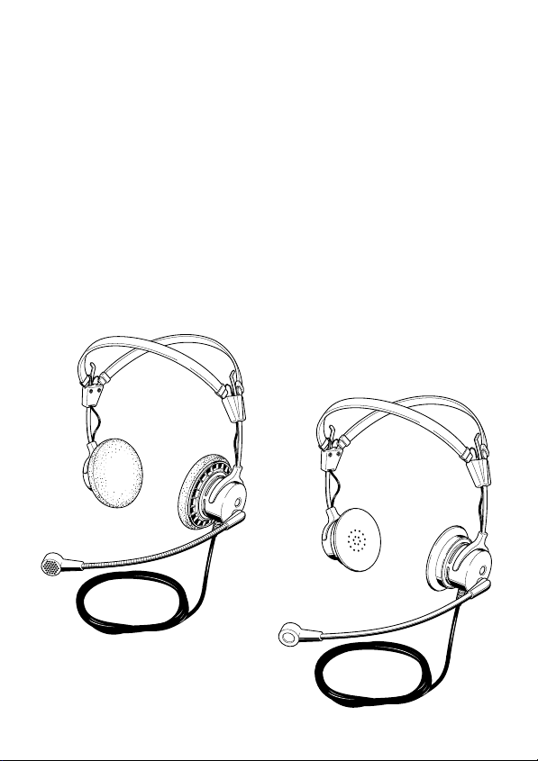
HME 45-6
Hör-/ Sprechgarnitur zum Anschluß an Vermittlungsplätze in Telefon-Vermittlungszentralen, für Konferenz und Dolmetscheranlagen wie auch für alle Kommunikationsendgeräte mit Speisemöglichkeit für ein Elektretmikrofon. Diese Garnitur wird
mit offenem Kabelende geliefert, so daß ein kundenspezifischer Anschluß möglich ist.
Bitte entnehmen Sie die Beschaltung dem Stromlaufplan auf Seite 27.
HME 45-C
Hör-/ Sprechgarnitur zum Anschluß an Vermittlungspläte in TelefonVermittlungszentralen, für Konferenz und Dolmetscheranlagen. Diese Garnitur
wird mit einem 5-poligen XLR-Stecker geliefert. Die Beschaltung des XLRSteckers entnehmen Sie bitte dem Stromlaufplan auf Seite 28.
HME 45 telcom
Hör-/ Sprechgarnitur zum Anschluß an Vermittlungsplätze in TelefonVermittlungszentralen oder an Telekommunikationsendgeräte mit entsprechender
Anschlußbuchse (Anschlußnorm der Deutschen Telekom AG 121 TR 9-5). Diese
Hör- / Sprechgarnitur ersetzt den Telefonhörer und ermöglicht ein "freihändiges"
Telefonieren. Stromlaufplan auf Seite 29.
HMD 45-6
Hör-/ Sprechgarnitur mit dynamischem Mikrofon. Keine Speisespannung
erforderlich. Die Garnitur wird mit offenem Kabelende geliefert, so daß ein
kundenspezifischer Anschluß möglich ist. Stromlaufplan auf Seite 27.
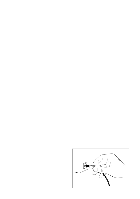
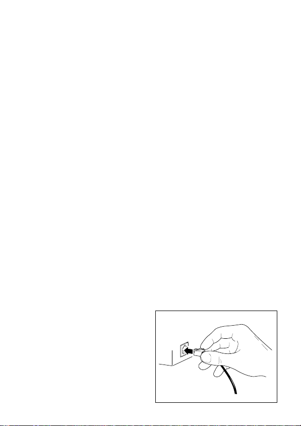
HME 45 telcom: Anschluß an ein Telefon
An Ihrem Telefon befindet sich eine für diese Hör- / Sprechgarnitur passende
Buchse. Sie ähnelt der Buchse, an der das Spiralkabel zum Hörer angeschlossen ist,
ist aber noch nicht belegt. Einige Hersteller kennzeichnen die Buchse mit dem
Symbol eines Kopfhörers oder mit der Bezeichnung "121 TR 9-5".
왘 Stecken Sie in diese Buchse die
Anschlußleitung der Hör- /
Sprechgarnitur HME 45 telcom.
(Abbildung )
왘 Lassen Sie den Telefonhörer auf
Ihrem Telefon liegen, Sie brauchen
ihn als "Schalter" zum Beginn und
zum Ende Ihres Gesprächs.
3
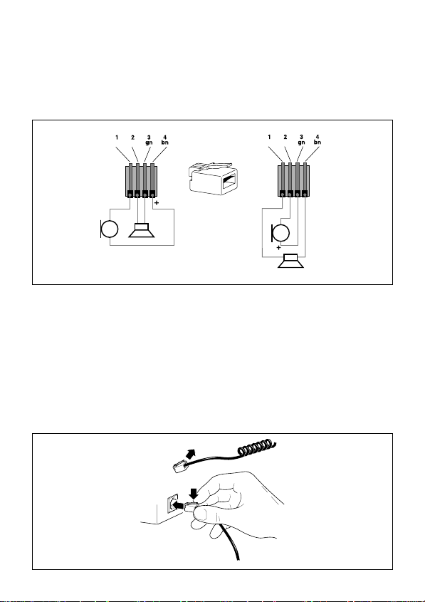
HME 45 telcom: Hinweise
Es existieren Telefone im Handel, bei denen die Buchsenbelegung zum Anschluß
einer Hör- / Sprechgarnitur nicht der Anschlußnorm der Deutschen Telekom AG
121 TR 9-5 entspricht. In diesem Fall müssen Sie sich einen Adapter anfertigen
lassen oder einen neuen Stecker anbringen. Abbildung zeigt die unterschiedliche
Anschlußbelegung am Anschlußkabel:
ye
wt
Deutsche Telecom
121 tr 9-5
ye
wt
Einige Telefone (speziell aus deutscher Fertigung) haben an der Anschlußbuchse
für den Telefonhörer eine für diese Hör- / Sprechgarnitur passende Beschaltung.
Speziell die erforderliche Speisespannung für das Kondensator-Mikrofon liegt
dann mit an.
Erkundigen Sie sich beim Hersteller Ihres Telefons, ob Sie eventuell eine Hör- /
Sprechgarnitur direkt anschließen können (Abbildung ). Er benötigt dazu einen
Schaltplan und die technischen Daten Ihrer Sennheiser Hör- / Sprechgarnitur
HME 45 telcom. Kopieren Sie ihm dazu die Seiten 6 und 29 dieser Anleitung.
4

Mikrofonarm einstellen
Kopfbügel einstellen
Kabel und Mikrofon von rechts oder von links
Kabel links
Kabel rechts
5

Technische Daten
Kopfhörer
Wandlerprinzip dynamisch, offen
Übertragungsbereich 20 Hz - 18 kHz
Impedanz 150 Ohm (mono) 300 Ω pro Seite (stereo)
Klirrfaktor < 1 %
Mikrofon HME 45-6 / HME 45-C / HME 45 telcom
Wandlerprinzip Back-Elektret-Kondensatorkapsel,
Übertragungsbereich bei
einem Abstand von 2 cm
zum Mundwinkel 100 Hz - 5 kHz
Ausgangsspannung HME 45 telcom: - 40 dBV/Pa nach 121 TR 9-5
Versorgungsspannung HME 45 telcom: 5 V DC
Mikrofon HMD 45-6
Wandlerprinzip dynamisches Mikrofon
Übertragungsbereich bei
einem Abstand von 2 cm
zum Mundwinkel 50 Hz - 12 kHz
Ausgangsspannung 0,5 mV/Pa
Impedanz 200 Ω
Allgemeine Daten
Kopfhörer-Andruckkraft ca 1,6 N
Gewicht ohne Kabel 140 g
Kabel einseitig, Länge gesamt: 1,8 m
Stecker HME 45 telcom: Westernstecker 4-pol
Lieferumfang 1 Hör- /Sprechgarnitur
Ausführungen HME 45 telcom: Westernstecker 4-pol
geräuschkompensiert
HME 45-6 / -C: - 35 dBV/Pa
HME 45-6 / -C: 3,5 - 10 V DC
HME 45-C: 5-poliger XLR-Stecker
HME 45-6: offenes Kabelende
HMD 45-6: offenes Kabelende
HME 45-C: 5-poliger XLR-Stecker
HME 45-6: offenes Kabelende
HMD 45-6: offenes Kabelende
6
HME 45-6
Headset for connection to terminals in telephone exchanges and switchboards or
to conference and interpretation systems. The headset is supplied with open-ended
cable so that the user can choose the connector most suitable for the application.
Please refer to page 27 for the wiring diagram.
HME 45-C
Headset for connection to terminals in telephone exchanges and switchboards or
to conference and interpretation systems. This headset is supplied with a 5-pin XLR
connector. Please refer to page 28 for the pin assignment of the XLR connector.
HME 45 telcom
Headset for connection to terminals in telephone exchanges and switchboards or
to telephones with suitable socket (as per 121 TR 9-5 connection standard of the
German Telekom). This headset replaces the receiver and leaves your hands free.
Please refer to page 29 for the wiring diagram.
HMD 45-6
Headset with dynamic microphone. No external supply voltage necessary. The
headset is supplied with open-ended cable so that the user can choose the connector
most suitable for the application. Please refer to page 27 for the wiring diagram.
Connection of the HME 45 telcom to a telephone
In the ideal case, your telephone is fitted with a suitable socket for connecting the
headset. Such a socket resembles the socket for the spiral cord of the receiver and
is unconnected. Some manufacturers use a headphone symbol for it, others the
designation „121 TR 9-5“.
왘 Connect the cable of your
HME 45 telcom headset to
this socket (see fig. ).
왘 The receiver remains on the
cradle. You need it as a „switch“
at the beginning and the end
of your phone call.
7

Please note for the HME 45 telcom
If your telephone has a headset socket not corresponding to the 121 TR 9-5
standard of the German Telekom, you have to have an adaptor made, or you have
to use a new plug. Figure shows the wiring arrangement.
ye
wt
ye
wt
Some telephones (especially from German manufacturers) have a receiver socket
suitable for the headset. In particular, this socket is able to supply the necessary
operating voltage for the condenser microphone.
Please ask your telephone manufacturer whether you can directly connect a
headset (fig. ). He will need the circuit diagram and the technical data of your
Sennheiser headset. Please photocopy pages 10 and 29 of these operating instructions
for him.
8
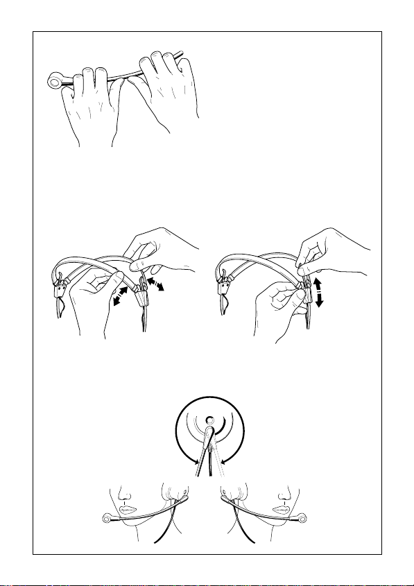
Adjusting the microphone boom
Adjusting the headband
Cable and microphone on the left or the right
Cable on the rightCable on the left
9

Technical data
Headphone
Transducer principle dynamic, open
Frequency response 20 Hz - 18 kHz
Impedance mono: 150 Ω, stereo: 300 Ω per side
THD < 1 %
Microphone HME 45-6 / HME 45-C / HME 45 telcom
Transducer principle noise-cancelling back-electret condenser
Frequency response
(2 cm distance between mic
and corner of mouth) 100 Hz - 5 kHz
Output voltage HME 45 telcom: -40 dBV/Pa as per 121 TR 9-5
Operating voltage HME 45 telcom: 5 V DC
Microphone HMD 45-6
Transducer principle Dynamic microphone
Frequency response
(2 cm distance between mic
and corner of mouth) 50 Hz - 12 kHz
Output voltage 0.5 mV/Pa
Impedance 200 Ω
Other
Contact pressure approx. 1.6 N
Weight (without cable) 140 g
Cable single-sided, total length 1.8 m
Connector HME 45 telcom: 4-pin western connector
Supply schedule 1 headset
Product variants HME 45 telcom: 4-pin western connector
microphone capsule
HME 45-6/ -C: -35 dBV/Pa
HME 45-6/ -C: 3.5 - 10 V DC
HME 45-C: 5-pin XLR connector
HME 45-6: open-ended cable
HMD 45-6: open-ended cable
HME 45-C: 5-pin XLR connector
HME 45-6: open-ended cable
HMD 45-6: open-ended cable
10

HME 45-6
Ensemble casque/micro pour utilisation dans des centraux téléphoniques ou pour
des systèmes de conférence et d´interprétariat. L´ensemble est livré avec extrémité
libre pour que l´utilisateur puisse choisir le connecteur approprié pour son
application. Pour les connexions du câble, veuillez vous référez à la page 27.
HME 45-C
Ensemble casque/micro pour utilisation dans des centraux téléphoniques ou pour des
systèmes de conférence et d´interprétariat. Cet ensemble est livré avec connecteur XLR
à 5 pôles. Pour les connexions du connecteur, veuillez vous référez à la page 28.
HME 45 telcom
Ensemble casque/micro pour utilisation dans des centraux téléphoniques ou pour
raccordement à des téléphones avec prise appropriée (selon la norme de connexion
121 TR 9-5 de la Telekom allemande). Cet ensemble casque/micro remplace le
combiné et vous donne une totale liberté d´action. Pour les connexions du
connecteur, veuillez vous référez à la page 29.
HMD 45-6
Ensemble casque/micro avec microphone dynamique. Aucune tension d‘alimentation
n‘est nécessaire au niveau du microphone. L´ensemble est livré avec extrémité libre
pour que l´utilisateur puisse choisir le connecteur approprié pour son application.
Pour les connexions du câble, veuillez vous référez à la page 27.
Raccordement a un telephone avec prise 121 TR 9-5
Dans le cas idéal, votre téléphone est muni d´une prise appropriée pour l´ensemble
casque/micro. Elle ressemble à la prise utilisée pour le câble hélicoïdal du combiné,
mais elle n´est pas encore branchée. Quelques fabricants la marquent avec le
symbole de casque, d´autres avec la désignation „121 TR 9-5“.
왘 Raccordez le câble de l´ensemble
casque/micro HME 45 telcom à
cette prise (voir fig. ).
왘 Le combiné reste sur le poste, il
sert comme „commutateur“ au
commencement et à la fin de vos
appels de téléphone.
11

N. B. pour le HME 45 telcom:
Si vous avez un téléphone auquel on peut raccorder un ensemble casque/micro
mais qui n´est pas conforme à la norme 121 TR 9-5 de la Telekom allemande, il
faut faire faire un adaptateur ou bien utiliser un nouveau connecteur. Figure
montre les connexions des câbles.
ye
wt
ye
wt
Quelques téléphones (notamment ceux des fabricants allemands) possèdent une
prise de combiné auquel on peut directement raccorder un ensemble casque/micro.
Cette prise a les connexions correctes et fournit la tension nécessaire pour le
microphone électrostatique.
Renseignez-vous auprès du fabricant de votre téléphone si vous pouvez directement
y raccorder un ensemble casque/micro (fig. ). Pour pouvoir vous donner cette
information, le fabricant a besoin du schéma des circuits et des connexions et des
caractéristiques techniques de votre ensemble casque/micro HME 45 telcom de
Sennheiser. Le mieux est de lui photocopier les pages 14 et 29 de cette notice
d´emploi.
12

Comment ajuster le microphone
Comment ajuster l´arceau du casque
Cable et microphone a gauche ou a droite
Câble à gauche
Câble à droite
13

Caracteristiques techniques
Casque
Principe transducteur dynamique, ouvert
Bande passante 20 Hz - 18 kHz
Impédance transducteur 150 Ω (mono), 300 Ω par (stéréo)
Distorsion harmonique < 1 %
Microphone HME 45-6 / HME 45-C / HME 45 telcom
Principe transducteur capsule à back-electret à
Bande passante (distance
entre microphone et le bord 100 Hz - 5 kHz
de la bouche: 2 cm)
Tension de sortie HME 45 telcom: -40 dBV/Pa selon 121 TR 9-5
Tension d´alimentation HME 45 telcom: 5 V DC
Microphone HMD 45-6
Principe transducteur Microphone dynamique
Bande passante (distance
entre microphone et le bord 50 Hz - 12 kHz
de la bouche: 2 cm)
Tension de sortie 0,5 mV/Pa
Impédance 200 Ω
Général
Pression exercée par les écouteurs approx. 1,6 N
Poids sans câble 140 g
Câble unilatéral, longueur totale 1,8 m
Connecteur HME 45 telcom: fiche Western à 4 pôles
Contenu 1 ensemble casque/micro
Variantes HME 45 telcom: fiche Western à 4 pôles
compensation du bruit
HME 45-6/ -C: -35 dBV/Pa
HME 45-6/ -C: 3,5 - 10 V DC
HME 45-C: connecteur XLR à 5 pôles
HME 45-6: extrémité libre
HMD 45-6: extrémité libre
HME 45-C: connecteur XLR à 5 pôles
HME 45-6: extrémité libre
HMD 45-6: extrémité libre
14

HME 45-6
Set cuffia / microfono per collegamento ai posti di commutazione nelle centrali di
commutazione telefonica, per impianti di conferenza e di traduzione simultanea. Questa
cuffia viene fornita con l’estremità aperta del cavo, per cui è possibile un collegamento
specifico del cliente. Per il collegamento si veda lo schema elettrico a pagina 27.
HME 45-C
Set cuffia / microfono per collegamento ai posti di commutazione nelle centrali di
commutazione telefonica, per impianti di conferenza e di traduzione simultanea.
Questa cuffia viene fornita con una spina XLR a 5 poli. Per il collegamento della
spina XLR si veda lo schema elettrico a pagina 28.
HME 45 telcom
Set cuffia / microfono per il collegamento ai posti di commutazione delle centrali
di commutazione telefoniche o ai telefoni („Terminali di telecomunicazione“) con
relativa presa di collegamento (norma di collegamento della Telekom Tedesca AG
121 TR 9-5). Questa cuffia sostituisce il microtelefono e permette di telefonare „a
viva voce“. Per il collegamento si veda lo schema elettrico a pagina 29.
HMD 45-6
Set cuffia / microfono con microfono dinamico. Non necessita di alimentazione
elettrica.Questa cuffia viene fornita con l’estremità aperta del cavo, per cui è
possibile un collegamento specifico del cliente. Per il collegamento si veda lo
schema elettrico a pagina 27.
HME 45 telcom: Collegamento ad un telefono
Sul Vostro telefono si trova una presa adatta a questa cuffia. Essa è simile alla presa,
alla quale è collegato il cavo a spirale per il microtelefono, non è tuttavia ancora
occupata. Alcuni costruttori contrassegnano la presa con il simbolo di una cuffia
o con la sigla „121 TR 9-5“.
왘 Innestate in questa presa il cavo di
collegamento della cuffia
HME 45 telcom. (Figura )
왘 Lasciate il microtelefono sul
Vostro telefono, esso Vi serve
come „interruttore“ all’inizio e
alla fine della conversazione.
15

HME 45 telcom: Avvertenze
In commercio esistono telefoni, nei quali la configurazione delle prese per il
collegamento di una cuffia non sono conformi alla norma di collegamento della
Telekom Tedesca AG 121 TR 9-5. In questo caso dovete far costruire un
adattatore oppure dovete applicare una nuova spina. La figura mostra la diversa
configurazione sul cavo di collegamento:
ye
wt
ye
wt
Alcuni telefoni (soprattutto quelli di produzione tedesca) hanno un cablaggio
adatto per questa cuffia sulla presa di collegamento per il microtelefono. In questo
caso è presente soprattutto la tensione di alimentazione necessaria per il microfono
a condensatore.
InformateVi presso il costruttore del Vostro telefono se potete eventualmente
collegare una cuffia direttamente (figura ). Il costruttore ha bisogno dello schema
di collegamento e dei dati tecnici della Vostra cuffia Sennheiser HME 45 telcom.
A tale scopo copiate le pagine 18 e 29 di queste istruzioni.
16

Regolare il braccio del microfono
Regolare la staffa della cuffia
Cavo e microfono da destra o da sinistra
Cavo a destraCavo a sinistra
17

Dati tecnici
Cuffia
Principio convertitore dinamico, aperto
Banda di trasmissione 20 Hz - 18 kHz
Impedenza 150 Ω (mono) 300 Ω per ogni lato (stereo)
Fattore di distorsione < 1 %
Microfono HME 45-6 / HME 45-C / HME 45 telcom
Principio convertitore Capsula condensatore contro-elettrodo
Banda di trasmissione ad una
distanza di 2 cm dall’angolo 100 Hz - 5 kHz
della bocca
Tensione di uscita HME 45 telcom: -40 dBV/Pa secondo 121 TR 9-5
Tensione di alimentazione HME 45 telcom: 5 V DC
Microfono HMD 45-6
Principio convertitore microfono dinamico
Banda di trasmissione ad una
distanza di 2 cm dall’angolo 50 Hz - 12 kHz
della bocca
Tensione di uscita 0,5 mV/Pa
Impedancia 200 Ω
Dati generali
Forza di pressione cuffia ca. 1,6 N
Peso senza cavo 140 g
Cavo su un lato, lunghezza totale: 1,8 m
Spina HME 45 telcom: spina Western a 4 poli
Volume di fornitura 1 cuffia
Esecuzioni HME 45 telcom: spina Western a 4 poli
elettrete, con compensazione del rumore
HME 45-6 / -C : -35 dBV/Pa
HME 45-6 / -C 3,5 - 10 V DC
HME 45-C: spina XLR a 5 poli
HME 45-6: estremità aperta del cavo
HMD 45-6: estremità aperta del cavo
HME 45-C: spina XLR a 5 poli
HME 45-6: estremità aperta del cavo
HMD 45-6: estremità aperta del cavo
18

HME 45-6
Combinación de auricular y micrófono para uso en puestos de trabajo en centrales de
información telefónica, para conferencias e instalaciones de interpretación simultánea.
El dispositivo se suministra con los extremos de los cables abiertos, para permitir al
cliente conectarlo según sus necesidades. En la página 27 se indica el modo de
conexión en el esquema del circuito amperimétrico.
HME 45-C
Combinación de auricular y micrófono para conectar en puestos de trabajo en centrales
de información telefónica, para conferencias e instalaciones de interpretación simultánea.
El dispositivo se suministra con un enchufe XLR de 5 polos. En la página 28 se indica
el modo de conexión del enchufe XLR en el esquema del circuito amperimétrico.
HME 45 telcom
Combinación de auricular y micrófono para conectar en puestos de trabajo en centrales
de información telefónica o en teléfonos („Aparatos de telecomunicación“) provistos
del casquillo de conexión apropiado (Norma de conexión de la Deutsche Telekom AG,
121 TR 9-5). El auricular del teléfono se reemplaza con esta combinación de auricular
y micrófono, que permite a quien la usa telefonear, manteniendo libres las manos. En
la página 29 se indica el modo de conexión en el esquema del circuito amperimétrico.
HMD 45-6
Combinación de auricular y micrófono con micrófono dinánico. No requiere tensión
de alimentación. El dispositivo se suministra con los extremos de los cables abiertos,
para permitir al cliente conectarlo según sus necesidades. En la página 27 se
indica el modo de conexión en el esquema del circuito amperimétrico.
HME 45 telcom: Conexion a un telefono
En su teléfono existe un casquillo apropiado para esta combinación de auricular y
micrófono. Este casquillo, que se encuentra libre, es similar al casquillo en el cual
se inserta el cable en espiral para el auricular. Algunos fabricantes señalan el
casquillo con el símbolo de un auricular o con la designación „121 TR 9-5“.
왘 Inserte en este casquillo el cable
conector del dispositivo combinado
de auricular y micrófono
HME 45 telcom. (Ilustración ).
왘 No levante el auricular del
teléfono, lo necesita como
„conmutador“ al principio y
al fin de su conversación.
19

HME 45 telcom: Indicaciones
Existen en el comercio teléfonos en los cuales la disposición del casquillo para
conectar un dispositivo combinado de auricular y micrófono no corresponde a la
norma de conexión de la Deutsche Telekom AG 121 TR 9-5. En tal caso será necesario
encargar un adaptador, o montar un nuevo enchufe. La ilustración indica las
diferentes posibilidades de conexión en el cable conector:
ye
wt
ye
wt
Algunos teléfonos (especialmente de fabricación alemana) tienen en el casquillo de
conexión para el auricular un circuito adecuado para este dispositivo combinado
de auricular y micrófono. De tal forma se logra también el voltaje de alimentación
necesario para el micrófono de condensador.
Pregunte al fabricante de su teléfono si existe la posibilidad de conectar directamente
un dispositivo combinado de auricular y micrófono (Fig. ). A tal fin necesita un
esquema de circuitos y los datos técnicos de su dispositivo combinado de auricular
y micrófono HME 45 telcom de Sennheiser. A tal efecto, sírvase remitirle
fotocopias de las páginas 22 y 29 de estas instrucciones.
20

Ajustar el brazo del microfono
Ajustar el aro del auricular
Cable y microfono a la derecha o a la izquierda
Cable a la izquierda
Cable a la derecha
21

Datos tecnicos
Casco auricular
Principio transductor dinámico, abierto
Margen de transmisión 20 Hz - 18 kHz
Impedancia 150 Ω (mono) 300 Ω por lado (estéreo)
Factor de distorsión < 1%
Micrófono HME 45-6 / HME 45-C / HME 45 telcom
Principio transductor Cápsula de condensador contraelectreto,
Margen de transmisión a
distancia de 2 cm al ángulo 100 Hz - 5 kHz
de la boca
Tensión de salida HME 45 telcom: -40 dBP/Pa según 121 TR 9-5
Tensión de alimentación HME 45 telcom: 5 V DC
Micrófono HMD 45-6
Principio transductor Micrófono dinamico
Margen de transmisión a
distancia de 2 cm al ángulo 50 Hz - 12 kHz
de la boca
Tensión de salida 0,5 mV/Pa
Impedenza 200 Ω
Datos generales
Fuerza de apriete del auricular Aprox. 1,6 N
Peso sin el cable 140 g
Cable Unilateral, largo total: 1,8 m
Enchufe HME45 telcom: enchufe occidental, 4 polos
El suministro incluye 1 dispositivo combinado de auricular y micrófono
Versiones HME45 telcom: enchufe occidental, 4 polos
con compensación de ruidos
HME 45-6 / -C: 3,5 dBV/Pa
HME 45-6 / -C: 3,5 - 10 V DC
HME 45-C: Enchufe XLR, 5 polos
HME 45-6: extremo del cable abierto
HMD 45-6: extremo del cable abierto
HME 45-C: Enchufe XLR, 5 polos
HME 45-6: extremo del cable abierto
HMD 45-6: extremo del cable abierto
22

HME 45-6
Luister-/spreekgarnituur voor de aansluiting aan telefooncentrales voor conferentie
en tolk-installaties. Deze garnituur wordt geleverd met open kabeluiteinden zodat
een specifieke aansluiting van de klant mogelijk is. U vindt de beschakeling in het
stroomloopschema op pagina 27.
HME 45-C
Luister-/spreekgarnituur voor de aansluiting aan telefooncentrales voor conferentie
en tolk-installaties. Deze garnituur wordt geleverd met een 5-polige XLR-stekker.
U vindt de beschakeling in het stroomloopschema op pagina 28.
HME 45 telcom
Luister-/spreekgarnituur voor de aansluiting aan telefooncentrales of aan telefoons
(telcommunicatie-eindapparaten) met overeenkomstige aansluitingsbus
(aansluitnorm van de Duitse Telekom AG 121 TR 9-5) Deze luister-/spreekgarnituur
vervangt de telefoonhoorn en maakt telefoneren met “vrije handen” mogelijk. U
vindt de beschakeling in het stroomloopschema op pagina 29.
HMD 45-6
Luister-/spreekgarnituur met dynamische microfoon. Geen voedingsspanning
nodig. Deze garnituur wordt geleverd met open kabeluiteinden zodat een specifieke
aansluiting van de klant mogelijk is. U vindt de beschakeling in het
stroomloopschema op pagina 27.
HME 45 telcom: Aansluiting aan een telefoon
Op uw telefoon bevindt zich een bus die op deze luister-/spreekgarnituur past. Deze
bus lijkt op de bus waaraan het spiraalvormige snoer van de telefoonhoorn is
aangesloten, is echter nog niet bezet. Sommige fabrikanten kenmerken deze bus
met het symbool van een hoofdtelefoon of met de aanduiding “121TR9-5”.
왘 Steek de aansluiting van de
luister-/spreekgarnituur
HME 45 telcom (afbeelding )
in deze bus.
왘 Laat de hoorn op uw telefoon-
toestel liggen. U heeft deze als
schakelaar aan het begin en het
einde van uw gesprek nodig.
23

HME 45 telcom: Opmerkingen
Er zijn telefoons in de handel verkrijgbaar waarbij de busbelegging van een luister/spreekgarnituur niet overeenkomt met de aansluitnorm van de Duitse Telekom
AG 121 TR 9-5. In dit geval moet u een adapter laten maken of een nieuwe stekker
aanbrengen. Afbeelding toont de verschillende aansluitbeleggingen van de
aansluitkabel.
ye
wt
ye
wt
Sommige telefoons (vooral die, die in Duitsland werden geproduceerd) hebben aan
de aansluitbus voor de telefoonhoorn een passende beschakeling voor deze luister/spreekgarnituur. Vooral de noodzakelijke voedingsspanning voor het condensatormicrofoon is dan ook aanwezig.
Informeer bij de fabrikant van ue telefoon of u eventueel een luister-/spreekgarnituur
direkt kunt aansluiten (afbeelding ). De fabrikant heeft hiertoe een schakelschema
en de technishe gegevens van uw Sennheiser luister-/spreekgarnituur HME 45
telcom nodig. Kopieer hiervoor de pagina’s 26 en 29 van deze gebruiksaanwijzing.
24

Arm van de microfoon instellen
Hoofdbeugel instellen
Kabel en microfoon van rechts of van links
Kabel links
Kabel rechts
25

Technische gegevens
Hoofdtelefoon
Omzetprincipe dynamisch, open
Frequentiebereik 20 Hz - 18 kHz
Impedantie 150 Ω (mono) 300 Ω per kant (stereo)
Vervormingsfactor < 1%
Microfoon HME 45-6 / HME 45-C / HME 45 telcom
Omzetprincipe Back-Elektret.condensatorcapsule
Frequentieweergave bij een
afstand van 2 cm tot de mondhoek 100 Hz - 5 kHz
Uitgangsspanning HME 45telcom: 40 dBV/Pa volgens 121 TR 9-5
Voedingsspanning HME 45telcom: 5 V DC
Microfoon HMD 45-6
Omzetprincipe Dynamische Microfoon
Frequentieweergave bij een
afstand van 2 cm tot de mondhoek 50 Hz - 12 kHz
Uitgangsspanning 0,5 mV/Pa
Impedantie 200 Ω
Algemene gegevens
Hoofdtelefoon-aandrukkracht ca. 1,6 N
Gewicht zonder kabel 140 g
Kabel eenzijdig, lengte totaal 1,8 m
Stekker HME 45telcom: westernstekker 4-polig
Leveromvang 1 luister-/spreekgarnituur
Uitvoeringen HME 45telcom: westernstekker 4-polig
ruis-gecompenseerd
HME 45-6/ -C: -35 dBV/Pa
HME 45-6/ -C: 3,5-10 V DC
HME 45-C: 5-polige XLR-stekker
HME 45-6: open kabeluiteinden
HMD 45-6: open kabeluiteinden
HME 45-C: 5-polige XLR-stekker
HME 45-6: open kabeluiteinden
HMD 45-6: open kabeluiteinden
26

Stromlaufplan / circuit diagram
schema des circuits et des connexions / schema elettrico
esquema del circuito amperimetrico / Stroomloopschema
HMD 45-6
red
blue
screen
screen
HMD 45-6 / HME 45-6
HME 45-6
blue
red
screen
screen
blue
blue
red
red
brown
brown
white
white
green
green
orange
orange
27

Stromlaufplan
circuit diagram
schema des circuits et des connexions
schema elettrico
esquema del circuito amperimetrico
Stroomloopschema
blue
green
screen
screen
blue
red
brown
HME 45-C
white
28

Stromlaufplan
circuit diagram
schema des circuits et des connexions
schema elettrico
esquema del circuito amperimetrico
Stroomloopschema
HME 45 telcom
29

Sennheiser electronic GmbH & Co. KG Telefon: +49(0)5130 600 0
D-30900 Wedemark Telefax: +49(0)5130 600 300
Printed in Germany Publ. 2/98 59377 / A 03
30
 Loading...