

Sennheiser GuidePort,GuidePort SR 3000-2,GuidePort AM 3000,GuidePort Receiver,Identifier Transmitter System Manual

GuidePort – EMP
System Manual
Version 1.0 of 27 July 2000
Sennheiser electronic GmbH & Co. KG
Am Labor 1
30900 Wedemark
Germany

GuidePort: System Manual 27. November 2000 Seite 2
1 GuidePort Wireless Audio Transmission
GuidePort is a local area broadcast system for use in museums, visitor centers and at
exhibitions. GuidePort features a characteristic cell structure, the so-called cells being
defined areas of information and entertainment. These areas are supplied by Cell
Transmitters which send digitally coded information via an Active Antenna Unit to
portable Receivers. The transmitted data can be any audio information, for example
comments or music. The audio signals are picked up by bodypack receivers which play
the audio program directly via headphones. The various audio programs (events) can
be triggered automatically by magnetic field identifiers.
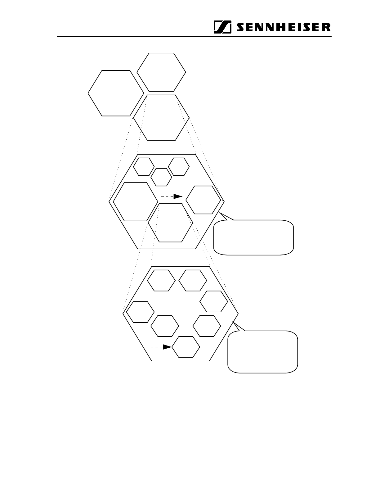
The diagram on the next page shows GuidePort’s system hierarchy. At the top level are
the GuidePort installations. Each installation carries a specific code transmitted via RF.
Whenever a GuidePort receiver recognizes a new installation code, it will automatically
collect the installation-specific control data. This data is mainly the so-called Event
Assign Table which defines the receiver’s “reactions” to the 255 possible event
numbers available in each installation, making the receiver compatible with other
separate, independent GuidePort installations.
An installation can be seen as a macro cell. Each installation can be organized in up to
255 cells and contains up to 255 real-time audio events.
GuidePort: System Manual 27. November 2000 Seite 3
GuidePor
t
Installation
INST. No. 1
GuidePor
t
Installation
INST. No. 3
GuidePor
t
Installation
INST. No. 2
cell 1
cell 2
cell 3
cell 4
…
cell 255
cell 5
GuidePort Cell
with one or more
Cell Transmitters
Event 1 Event 2
Event 3
Event 5
Event 4
Event 6
Event
One installation
can handle up to 255 events
which may be organized in
up to 255 cells
GuidePort System Hierarch
y
One
cell transmitter
can handle up to 4
mono audio channels
and transmit them on
one RF channel
GuidePort: System Manual 27. November 2000 Seite 4
Cell Transmitte
r
Central Unit PC with
• GP Central Unit
Software
• Sound card with a
samplingrateof
32 kHz
• G7++ converter and
announcement
software
Base Station PC
with
Cell Transmitter
Loader Software
Base Station PC
with
Cell Transmitter
Loader Software
Audio Source 1 -4
PC Network
Base Station PC
with
Cell Transmitter
Loader Software
USB Hub
USB
USB Hub
Audio Source 1 -4
Active
Antenna Unit
RF CH 1
Cell Transmitte
r
Active
Antenna Unit
RF CH 4
Cell Transmitte
r
Event
#3
Event
#4
Event
#5
Event
#6
GP
Receiver
Ext.
Antenna
(
opt.
)
Event
#2
Event
#1
Exhibition
room 1
Exhibition
room 2
Exhibition
room 3
Exhibition
room 7
Technical
room 1
LVDS
LVDS
USB
Exhibition
room 5
Exhibition
room 6
Exhibition
room 4
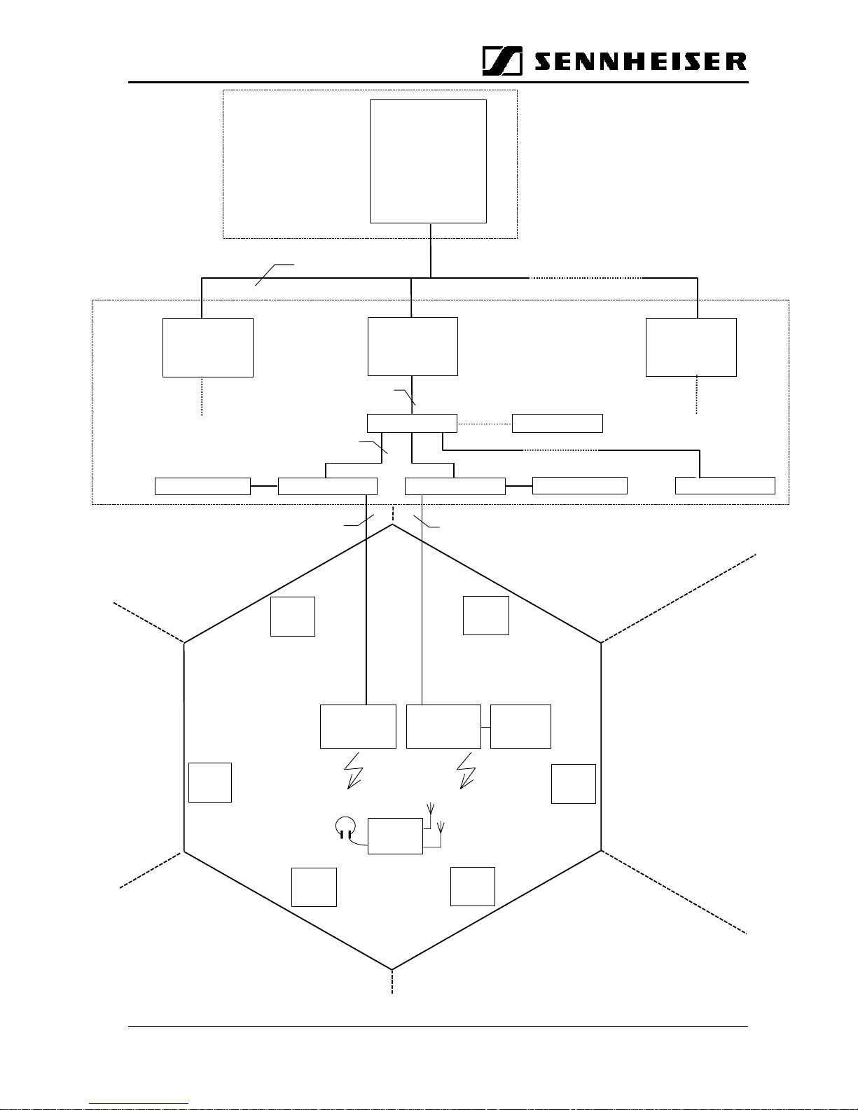
Technical equipment required for an exhibition with GuidePort
Supervisor
GuidePort: System Manual 27. November 2000 Seite 5
2 Hardware Components of the System
2.1 Central Unit PC
The Central Unit PC with its Central Unit Software is at the heart of the GuidePort
system. It serves to configure the entire GuidePort installation with its cells,
transmitters, events and identifiers. Via a network, the Central Unit PC is connected
with all Base Station PCs of the GuidePort installation.
2.2 Base Station PC
The Base Station PC with its Cell Transmitter Loader Software detects the IDs of all
Cell Transmitters connected to it via a USB. The Base Station PC will transmit the
configuration files created by the Central Unit Software to the Cell Transmitters.
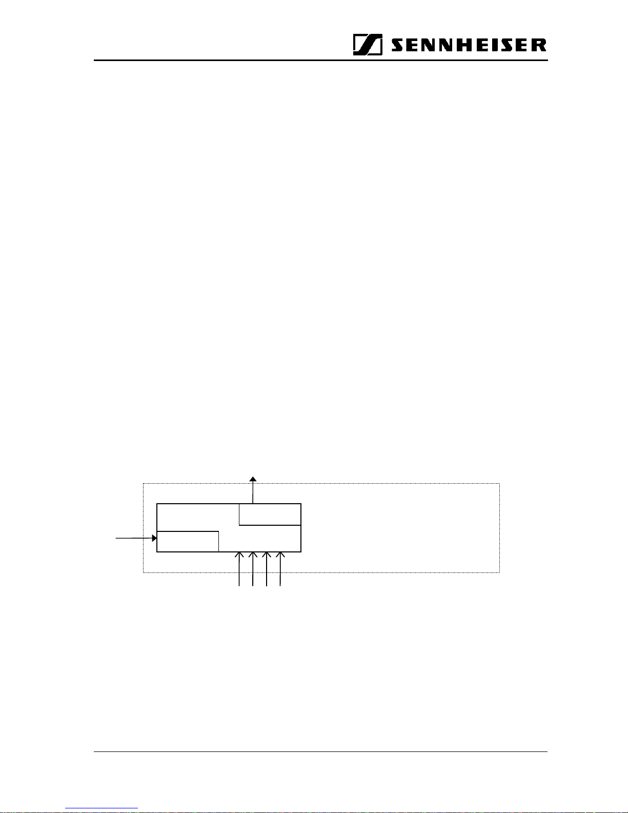
2.3 Cell Transmitter
2.3.1 Description
A Cell Transmitter is a digital unit which picks up prepared MTS data and combines
them with installation-specific control tables and the real-time audio information from its
four analog audio inputs. Via an LVDS interface, the entire data stream is sent to an
Active Antenna Unit where FSK modulation and RF conversion take place. The
transmission of the MTS data is done in a cyclic manner. The cable length between the
Cell Transmitter and the Active Antenna Unit may amount to up to 150 m, which
ensures a convenient installation of the local antennas.
1234
Analog RTA Inputs
Cell Controller
Unit
USB
Interface
LVDS
Interface
Data
Download
To Active Antenna Unit
Base Station
GuidePort: System Manual 27. November 2000 Seite 6
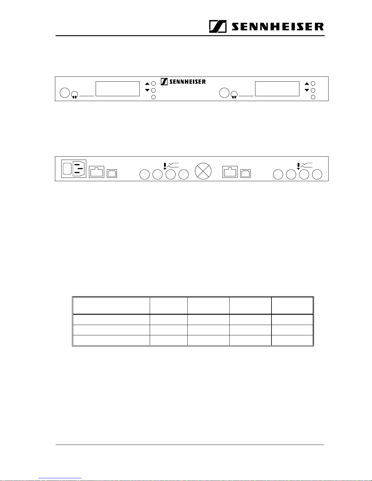
2.3.2 Hardware Interfaces
a) Front panel
Headphone Outputs
Allow you to monitor the audio signals transmitted to the receivers.
b) Rear panel
USB IN:
Input socket for the USB cable from the Base Station PC.
ANALOG IN SYM.:
Inputs for connecting your audio sources to the transmitter. There are four balanced
inputs, you can either connect 4 mono sources, 2 mono sources and 1 stereo source or
2 stereo sources. For a stereo audio source, you will need two sockets (left and right
channel), please use inputs 1 & 2 and/or 3 & 4. Connect the left audio channel to
socket No. 1 or 3, the right audio channel to No. 2 or 4, respectively.
The following table shows how to connect your audio sources to the GuidePort Cell
Transmitter:
Number and kind of audio
sources
Input No. 1 Input No. 2 Input No. 3 Input No. 4
4 mono (m) m m m m
2mono(m),1stereo(s) m m s,left s,right
2 stereo (s) s, left s, right s, left s, right
AAU OUT
Output for connection of an Active Antenna Unit. Use a shielded, 8-wire twisted pair
cable (4 individually twisted pairs) for connection. This cable supplies the Active
Antenna Unit with DC and the digital data stream to be transmitted.
SET SET
GuidePortSR3000
-2
TX I TX II
TX II
AAU OUT
0
I
USB IN
ANALOG IN SYM.
TIP: +
-
1
234
TX I
AAU OUT
USB IN
ANALOG IN SYM.
TIP: +
-
1
234
 Loading...