

INSTRUCTION FOR USE
EM 203

CONTENTS
1 TECHNICAL OVERVIEW
1.1 Computer Control
1.2 Diversity
1.3 HIDYN plus® noise reduction system
1.4 Block diagrams
2 POSSIBLE TRANSMITTER/RECEIVER COMBINATIONS
2.1 EM 203 receiver/SK 2012 TV(HiDyn plus®) and SKM 4031 HiDyn plus
2.2 EM 203 receiver/SK 50/250 UHF and SKM 5000 (HiDyn plus®)
2.3 EM 203 receiver/SER 20 transceivers
3 PUTTING THE EM 203 TO WORK
3.1 Mains connection
3.2 Antenna connection
3.3 AF connection
3.4 Start-up procedure/operating indicators
4 AVAILABLE MODULES
4.1 EM 1046 RX RECEIVER MODULE
4.1.1 Adjustment
4.1.2 Receiver frequencies
4.1.3 Squelch
4.1.4 Selection RF signal/deviation/battery condition
4.1.5 Display-text/frequency/battery condition
4.1.6 Entry of brief text
4.1.7 System configurations and specifications
4.1.8 Remote monitoring of transmitter battery
4.1.9 Monitoring of audio signals
4.1.10 Stand-by
®
4.2 MONITOR
4.2.1 LED indicators
4.2.2 Monitor headphones
5 TECHNICAL DATA

Introduction
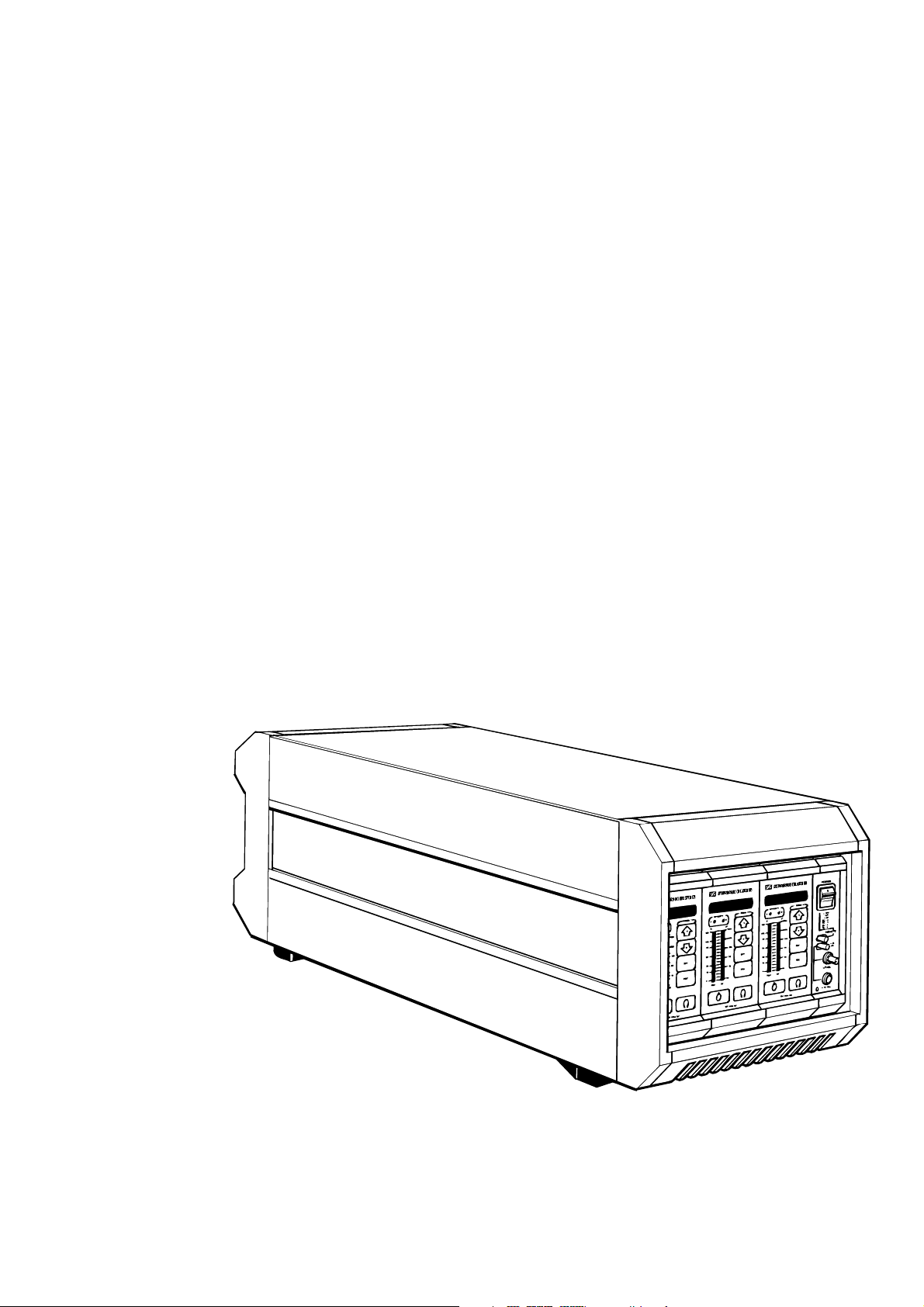
The wireless Mikroport multi-channel sound transmission system EM
1046 is a transmitter/receiver system in a modular design. It offers
comfortable handling and can be relied on for dependable service.
• 3-channel diversity receiver EM 203 with microprocessor-controlled
receiver modules
• Ultimate flexibility in the selection of transmitter and receiver
frequencies thanks to easy-to-replace PROMs and EEPROMs.
The present manual shall help you to get acquainted with the EM 203
receiver.
• The chapter "START-UP PROCEDURE" helps you to connect the
unit to the mains and to put it to work.
• The chapter "AVAILABLE MODULES" provides you with
information on every single module. It explains how to adjust them
to satisfy your individual transmission requirements.
The necessary modules for this receiver system are incorporated into a
"Mainframe". For programming and servicing, the EM 1046 RX
receiver modules can be removed to the front. Output module, input
module and mains power supply module, however, are integral parts of
the system.
IMPORTANT INFORMATION
Each HF input is supplied with a wideband power distributor 1:3,
which intendedly does not affect the adjustment possibilities of the
EM 1046 RX receiver modules. In order to achieve sufficient sensitivity
and protection against subscriber's extention stations, an antenna with
booster and pre-selection is required. In general, Sennheiser's
AB 1036 TV antenna booster is used.
Refer programming of the EEPROMs in the receiver modules to
qualified service personnel or Sennheiser's Service Department,
30900 Wedemark, Germany.

Technical overview 1
Computer control 1.1
Diversity 1.2
HiDyn plus® noise reduction 1.3
Block diagrams 1.4

Computer control
1.1
Every single EM 1046 RX receiver module has an in-built microprocessor for the RF section, the operating elements and all indicators.
It serves to control the following components or parameters:
• phase locked loop (PLL) synthesizer
• function of keys
• 8 digit LED display
• two LED bargraph displays
• true diversity
• monitoring
• squelch threshold
• description fields
• stand-by
• storage of all receiver parameters (e. g. receiver frequencies) in a
permanent memory
During diversity operations, the microprocessor controls every one of the
two receiver chains that are combined on one module.
The receiver parameters and the selectable frequencies can easily be
changed with the help of a conventional computer system as every
receiver module incorporates an additional service interface. Changes
are only possible within the admissible RF bandwidth.
The software can easily be adapted to your individual requirements and
updated at any time by Sennheiser’s Service Department. Our
servicemen simply replace the PROM in the receiver modules.
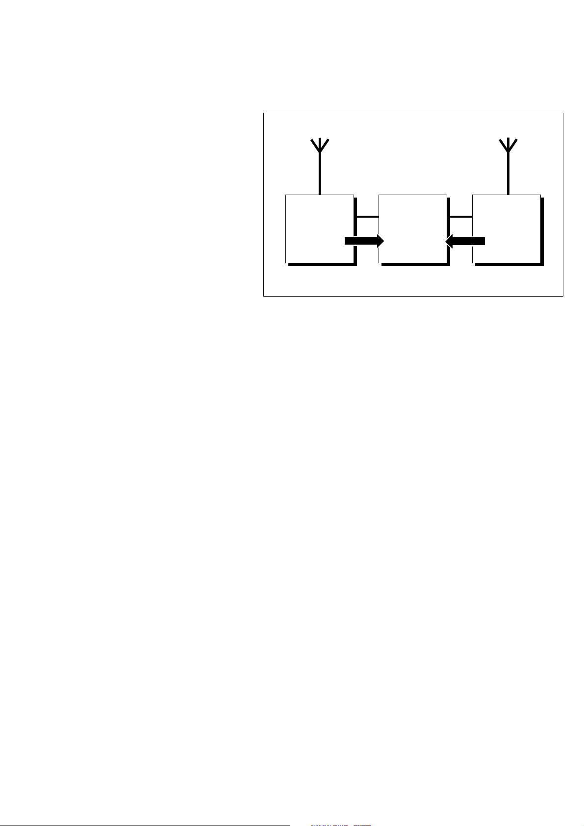
Diversity
1.2
Receiver 1
Control signal
Automatic electronic switching
of audible frequency signal
Steuersignal
Control signal
Receiver 2
Every EM 1046 RX receiver module operates on true diversity.
An antenna splitter, integrated into the chassis, serves to route the
antenna signals from both antennas to the three receiver modules.
The receiving antenna not only receives direct electromagnetic waves,
but also reflections from walls, windows, ceilings and other installations,
which results in the cancellation of these waves, so-called „field strength
gaps“. Repositioning the receiving antenna is a possible remedy,
provided the transmitter remains in its original position. However,
as most transmitters are used for portable applications, the
„field strength gaps“ then occur in other positions. The effects of
field strength variations can only be eliminated through the use
of true diversity techniques.
Sennheiser’s specially developed diversity system is based on two
receivers operating on the same frequency and two separate antennas.
A comparator ensures that the receiver with the strongest RF signal is
automatically and noiselessly switched to the AF output. Diversity
operations can compensate for considerable variations in field strength,
thus providing an enormous gain in transmission reliability.
Nota bene: Every single EM 1046 RX receiver module incorporates two
receivers for diversity operation.
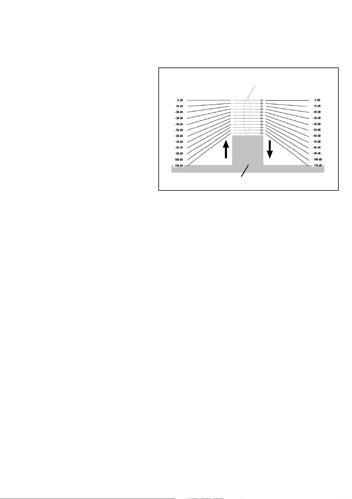
HiDyn plus
®
DYNAMICS OF THE AUDIO SIGNAL
IN THE RF-SIGNAL (MAX 60 DB)
1.3
DYNAMICS OF THE AF INPUT SIGNAL
COMPRESSION AT
THE TRANSMITTER
HIDYN plus
SYSTEM NOISE PLUS MODULATION/DEMODULATION
®
NOISE IN THE TRANSMITTER PATH
EXPANSION AT THE
RECEIVER
HIDYN plus
®
»HIDYN plus®« NOISE REDUCTION SYSTEM
The »HIDYN plus®« noise reduction system serves to reduce the effects
of RF interference fields. It increases the signal-to-noise ratio and gets
close to about 110 dB for peak modulation.
DYNAMICS OF THE AF OUTPUT SIGNAL
»HIDYN plus®« is a wideband compander system. It is a combination of
a compressor at the transmitter (ratio 2:1) and an expander at the
receiver, the compressor reducing the volume of the signal and the
expander restoring it. The optimized dynamic range and the control
amplifier in the transmitter effectively reduce modulation problems.
»HIDYN plus®« has been expecially developed by Sennheiser for studio
and stage applications.
Its features:
• extemely low degree of noise modulation
• level compensation
• excellent dynamic range due to the control amplifier
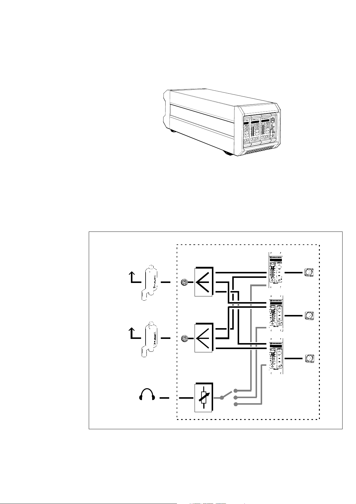
Block diagram EM 203
1.4

Possible transmitter/ 2
receiver combinations
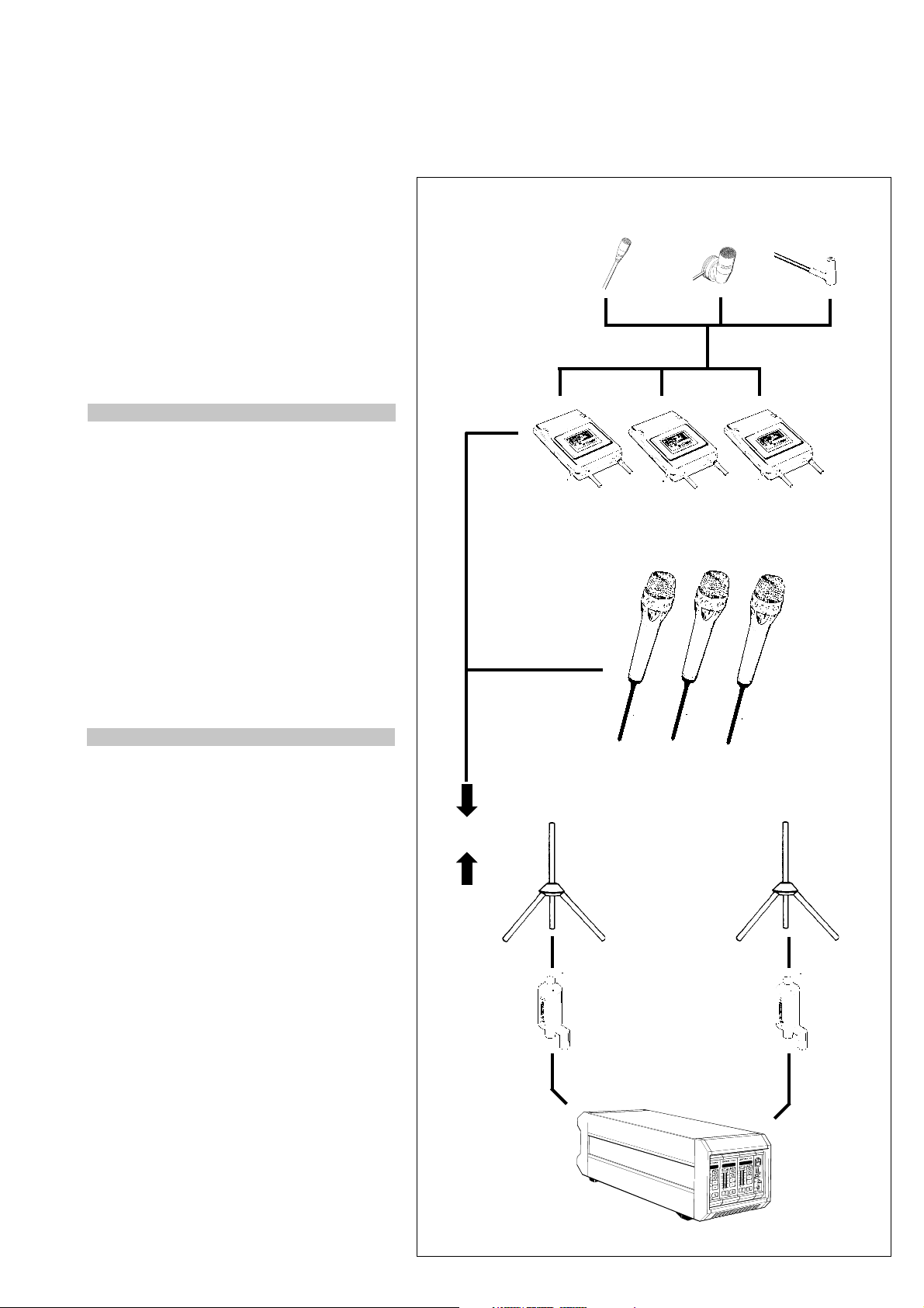
EM 203 receiver/ 2.1
SK 2012 TV (HiDyn plus®)
and SKM 4031 TV-HiDyn plus
Transmitters
EM 203 receiver/ 2.2
SK 50/250 UHF
and SKM 5000 (HiDyn plus
Transmitters
EM 203 RECEIVER/ 2.3
SER 20 TRANSCEIVER
®
®
)
EM 203 receiver/
SK 2012 TV (HiDyn plus®)
and SKM 4031 TV-HiDyn plus
2.1
®
NOTA BENE
SK 2012 body-pack transmitters can be
retrofitted (change from HIDYN® to HIDYN
plus®) to make them suitable for use with EM
1046 receivers.
To this purpose please send the transmitters to
be retrofitted to Sennheiser's Service Department, 30900 Wedemark.
Attention: After the transmitters have been
retrofitted, they are no longer compatible with
HIDYN
®
.
MKE 2-2 R
SK 2012 TV (HiDyn plus®)
MKE 10-2 R
MKE 102-2 R
NOTA BENE
SKM 4031 TV transmitter microphones can be
used in conjunction with EM 203 systems if
they incorporate a HIDYN plus® compander.
This is the case with SKM 4031 HIDYN plus
®
condenser microphones.
Models incorporating a compander can be
retrofitted. To this purpose please send the
microphones to Sennheiser's Service Department, 30900 Wedemark, Germany.
Attention: After the transmitters have been
retrofitted, they are no longer compatible
with HIDYN
®
.
SKM 4031 TV-HiDyn plus
2 GZA 1036 TV
450 - 800 MHz
or
2 GZA 1036-9
140 -960 MHz
AB 1036 TV
®
EM 203 receiver
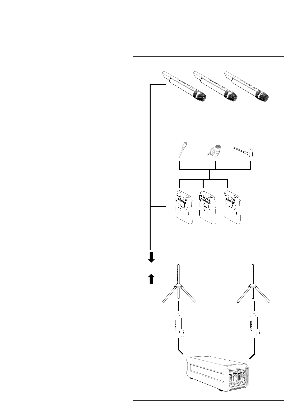
EM 1046/ SK 50 UHF / SK 250 UHF and SKM 5000
2.2
SKM 5000
MKE 2-4
MKE 10-4
SK 50 UHF / SK 250 UHF
2 GZA 1036 TV
450 - 800 MHz
or
2 GZA 1036-9
140 -960 MHz
MKE 102-4
EM 203 receiver
AB 1036 TV
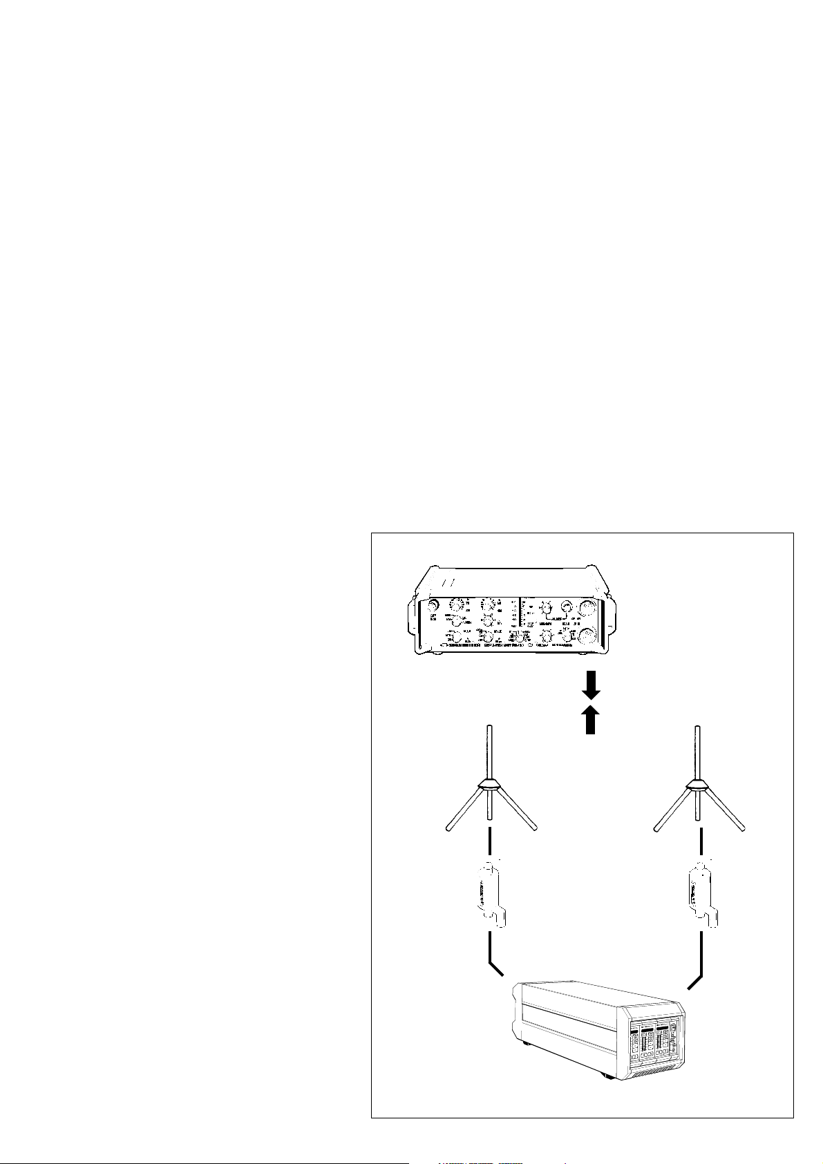
EM 203 receiver/ 2.3
SER 20 transceiver
Retrofitted SER 20 transceivers (change from
HIDYN© to HIDYN plus©) can be used in
conjunction with EM 203 receivers.
Refer retrofitting to Sennheiser distributors
or Sennheiser's Service Department,
30900 Wedemark, Germany.
At the time that the present brochure went to
print the retrofit kit for the SER 20 transceiver
was already under development. Please contact
your Sennheiser distributor for further
information on the exact date of delivery.
Another possibility:
If you don't need the advantages of HIDYN
plus© (e.g. in order to operate with older
equipment), the EM 203 receiver can be
modified to HIDYN©.
2 GZA 1036 TV
450 - 800 MHz
or
2 GZA 1036-9
140 -960 MHz
AB 1036 TV
SER 20 transceiver
with HiDyn plus
©
EM 203 receiver

Putting the EM 203 receiver 3
to work
Mains connection 3.1
Antenna connection 3.2
AF connection 3.3
Start-up procedure/
operating indicators 3.4
MANIPULATION
FUNCTION
DISPLAY
(RX)
13EM 203, Publ. 10/94 engl

Power is supplied by a plug-in power supply
unit.
The power module is available as a 110, 230 or
240 V AC model. The unit can easily be
adapted to changing power requirements by
replacing the power module.
Connection of the plug-in power supply unit is
via socket P at the back panel of the EM 203.
Mains connection 3.1
P
The two antennas needed for diversity
operation (see ch. 1.2) connect to sockets
A and B on the EM 302RI module
(N-type sockets).
The AB 1036 TV antenna boosters connected
in series are powered via sockets A and B. The
supply voltage can be switched on or off by
means of the switches next to the antenna
sockets.
If the antenna boosters are in operation, the
control LEDs for the booster supply voltage
light up at the front panel (→ ch. 4.2.1).
The AF output signals from every single EM
1046 RX receiver module are available at AF
outputs 1 to 3 on the EM 203 module (floating,
transformer-balanced). The connection is made
through XLR-3 plugs.
Antenna connection 3.2
ANTENNA
SOCKET
A
ANTENNA
SOCKET
B
AF connection 3.3
The switches at the left-hand side of the XLR
outputs ("PAD") allow to attenuate the output
signals by 20 dB.
AF-OUTPUTS
1 - 3
(MAX +18 DB)

Start-up procedure/ 3.4
Operating indications
POWER
+ 12 V
- 12 V
+ 5 V
DC - A
DC - B
OL - A
OL- B
REMOTE
+ 20
dB
+ 20 dBu
MANIPULATION
Switch on the receiver:
NOTA BENE
Put the transmitters to work (see their user’s
guide).
Check both transmitters and receivers for
identical frequencies. Check whether or not
the transmitters’ battery capacity is sufficient
for the planned applications.
FUNCTION
This is how the channel module indicates that
it is ready for operation (after power-up). The
three LED indicators for the operating voltages
light up (see ch. 4.2.1).
The display changes after about 5 seconds
It shows the frequency on which the mdoule is
operating
or
the name of the user, e. g. "THE CAT":
DISPLAY
(RX)
Sennheiser SK 50, SK 250 and SK 5000
Mikroport transmitters automatically
transfer data on the condition of their
batteries or rechargeable battery packs to
the EM 203receiver. If the LowBatt indicator
starts blinking on one of the displays, the
batteries or rechargeable battery packs
of the transmitters concerned are to be
replaced or recharged.
The capacity of the transmitter battery is
insufficient for proper operation.
The transmitter will be switched off in
about 10 minutes.
15EM 203, Publ. 10/94 engl

Available modules 4
EM 1046 RX 4.1
receiver module
Monitor 4.2

EM 1046 RX receiver module 4.1
Adjustment 4.1.1
Receiver frequencies 4.1.2
Squelch 4.1.3
Selection 4.1.4
RF Signal level/deviation/
battery condition
Display 4.1.5
Text/frequency/battery condition
Entry of brief texts 4.1.6
System configurations
and specifications 4.1.7
Remote monitoring 4.1.8
Of transmitter battery
Monitoring of audio signals 4.1.9
Stand-by 4.1.10

OPERATING ELEMENTS ON THE EM 1046 RX MODULE
RACK CONNECTOR
(invisible)
8 DIGIT
ALPHANUMERIC
LED DISPLAY
KEYS TO CONTROL
THE MENU AND TO
PROGRAM THE MODULE
DIVERSITY
CHANNELS
LED BARGRAPH DISPLAYS FOR
DEVIATION/RF SIGNAL LEVEL/
BATTERY CONDITION
STAND-BY
INDICATOR FOR REMOTE
MONITORING
MONITOR KEY
APPROVAL NUMBER

Adjustment 4.1.1
Y
N
SET
ESC
MENU
AB
DIVERSITY
MANIPULATION
Depress an arbitrary menu key on the
EM 1046 RX receiver module:
Y
or:
N
or:
SET
or:
ESC
Different functions can be selected from the
menu by depressing the following keys:
N
DOWN
UP
Y
FUNCTION
The receiver switches to the menu mode. It is
now ready for data entry.
Receiver operation remains unaffected.
The receiver is not set to the new parameters
unless the new data are stored!
Selection of receiver frequencies
Please see chapter 4.1.2
Squelch
Please see chapter 4.1.3
LED bargraph displays for RF signal level/
deviation/battery condition
Please see chapter 4.1.4
DISPLAY
(RX)
NOTA BENE
Depress
to return to the previous level.
This key also serves to stop data entry in case
of errors.
ESC
Display - text or frequency
Please see chapter 4.1.5
Text
Please see chapter 4.1.6
Display of EM 1035 RX configuration and
identification data
Please see chapter 4.1.7
Battery condition (SK 50/250)
Please see chapter 4.1.8
19EM 203, Publ. 10/94 engl

Receiver frequencies 4.1.2
3
3
3
3
3
3
3
3
3
3
3
3
3
3
3
3
3
3
3
3
3
3
3
3
3
3
3
MANIPULATION
Chose option "RX-Freq." (chapter 4.1.1).
Depress
SET
FUNCTION
DIVERSITY
AB
MENU
Y
N
SET
ESC
DISPLAY
(RX)
to allow the receiver frequencies to be selected.
The "M" on the display starts blinking.
2
2
2
2
2
2
2
2
2
2
2
2
2
2
2
2
2
2
24 MHz maximal
24 MHz maximal
The EM 1046 RX receiver module can be configured as follows:
• operation on max. 32 switchable frequencies or
• variable adjustment of receiver frequencies (5 kHz grid) within
16 frequency ranges
The frequencies or frequency ranges selected must fall within the
system's 24 MHz window. The configuration selected is stored in the
EM 1046 RX receiver module by a personal computer via the service
interface or by the remote computer. The configuration can be changed
as often as desired.
Refer changes to the system configuration to your authorized
Sennheiser distributor.
Example 1:
Variable adjustment within one frequency range (in the present case the
total bandwidth of the system.
Example 2:
Variable adjustment within three frequency ranges. The frequencies
between two adjacent frequency ranges cannot be used.
2
2
2
2
2
2
2
2
2
24 MHz maximal
Example 3:
Seven selectable frequencies. The EM 1046 RX receiver modules come
with this standard setting.
20EM 203, Publ. 10/94 engl

CONTINUED FROM PAGE 20 / CH. 4.1.2
MANIPULATION
Use keys
Y
N
to select a receiver frequency as per
pre-programmed parameters.
• Keeping the key depressed
acdelerates selection.
Depress
SET
UP
DOWN
FUNCTION
• Freely selectable receiver frequencies can
easily be adjusted in a 5 kHz grid. The unit
changes automatically from one grid to
another.
• For standard frequencies the display
automatically switches to the next channel.
DISPLAY
(RX)
to store new frequency.
NOTA BENE
Depress
ESC
to return to the previous level.
This key also serves to stop data entry in case
of errors.
Receiver operation remains unaffected.
The receiver is not set to the new parameters
unless the new data are stored!
21EM 203, Publ. 10/94 engl

CONTINUED FROM PAGE 21 / CH. 4.1.2
MANIPULATION
Depress
to store data
or depress
or
to stop storage.
Y
N
ESC
Y = YES !
N = NO !
FUNCTION
The new frequency is stored in the memory.
The EM 1046 RX receiver module switches to
the new frequency selected.
For a short time the display indicates
The program returns to the selection mode.
Additional frequencies can be selected, if
need be. The program returns to the menu.
The display shows:
DISPLAY
(RX)
NOTA BENE
Depress
ESC
to return to the previous level.
This key also serves to stop data entry in case
of errors.
22EM 203, Publ. 10/94 engl

Squelch 4.1.3
Y
N
SET
ESC
MENU
AB
DIVERSITY
MANIPULATION
Choose option „Squelch“ (see ch. 4.1.1)
Depress
to allow the squelch threshold to be set.
Use keys
to select the squelch threshold.
• Keeping the key depressed accelerates
adjustment.
Depress
SET
Y
N
SET
UP
DOWN
FUNCTION
The squelch threshold can be set in 140 steps.
The display indicates the level selected.
In addition, the left-hand LED bargraph
display indicates the squelch threshold:
• Use the RF scale (µV) to read off the
squelch threshold.
The squelch threshold can be additionally
checked on the monitor (monitor - see
ch. 4.1.8).
DISPLAY
(RX)
and subsequently:
to store the squelch threshold
or
depress
or:
to stop storage.
Y
N
ESC
Y = YES !
N = NO !
The new data are stored.
The display changes to „Menu“.
The program returns to the input routine.
New data can be selected, if need be. The
program returns to the menu. The display
shows:
23EM 203, Publ. 10/94 engl

Selection 4.1.4
RF signal level/deviation/batery condition
MANIPULATION
Choose option "DEV", "RF" or "BAT" to
indicate the RF signal level, deviation or
battery condition.
Depress key
SET
DIVERSITY
AB
MENU
Y
N
SET
ESC
FUNCTION
It is useful to have permanent settings to
facilitate day-to-day applications. The LED
bargraph displays on the EM 1046 RX
receiver module can be set to four different
modes:
DISPLAY
(RX)
to allow selection.
Depress key
Y
N
DEVIATION/FIELD STRENGTH OF THE ACTIVE CHANNEL
FIELD STRENGTH OF CHANNELS A AND B (DIVERSITY)
to select the parameters to be indicated.
COMPARISON BETWEEN DEVIATION OF CHANNEL A
AND B (DIVERSITY)
TRANSMITTER BATTERY CONDITION/FIELD STRENGTH
FOR FURTHER INFORMATION ON DATA INDICATED PLEASE REFER TO THE FOLLOWING PAGES!
After you have selected the data to be
indicated,
depress
SET
and subsequently
Y
Y = YES !
The new setting is stored.
The display changes to „Menu“.
or depress
or
to stop storage.
N
ESC
N = NO !
The program returns to the original setting, e. g.
New data can be selected, if need be. The
program returns to the menu. The display
shows:
24EM 203, Publ. 10/94 engl

DEV.
DIVERSITY
AB
MENU
Y
N
SET
CONTINUED FROM PAGE 24, CH. 4.1.4
MANIPULATION
N
SET
Y
Y
Y = YES !
Use
or
to select the parameters to be indicated.
Depress
and subsequently
to store the latest setting
RF.
FUNCTION
DEVIATION/FIIELD STRENGTH
to be indicated:
ESC
DISPLAY
(RX)
or depress
to stop storage.
After having depressed
and
N
Y
ESC
N = NO !
The left-hand bargraph display indicates
DEV (= Deviation) in %
The right-hand bargraph display shows the
field strength (RF= Radio Frequency) in µV
150
100
%
Peak Hold
DEV
µV
1000
100
RF
25EM 203, Publ. 10/94 engl

CONTINUED FROM PAGE 25, CH. 4.1.4
RFA
RFB
DIVERSITY
AB
MENU
Y
N
SET
ESC
MANIPULATION
Use
or
to select the parameters to be indicated.
Depress
and subsequently
to store the latest setting
or depress
to stop storage.
After having depressed
and
Y
N
SET
Y
N
Y
ESC
Y = YES !
N = NO !
FUNCTION
FIELD STRENGTH OF CHANNELS A/B (DIVERSITY)
to be indicated:
The left-hand bargraph display indicates
Field strength(RF = Radio Frequency) in µV
for diversity channel A
DISPLAY
(RX)
µV
1000
100
NOTA BENE
This display allows to monitor the RF level of
both diversitiy channels and indicates possible
antenna problems.
The right-hand bargraph display shows the
field strength (RF = Radio Frequency) in µV
for diversity channel B
The scale in µV near the right-hand bargraph
display is to be used for both LED bargraph
displays.
RF
µV
1000
100
RF
26EM 203, Publ. 10/94 engl

DEV A
DIVERSITY
AB
MENU
Y
N
SET
CONTINUED FROM PAGE 26, CH. 4.1.4
MANIPULATION
Use
or
to select the parameters to be indicated.
Depress
and subsequently
to store the latest setting
Y
N
SET
Y
Y = YES !
DEV B
FUNCTION
DEVIATION CHANNELS A/B (DIVERSITY)
to be indicated:
ESC
DISPLAY
(RX)
or depress
N
N = NO !
to stop storage.
After having depressed
and
Y
ESC
NOTA BENE
The read-outs of both bargraph displays differ
from each other only in case of faulty
functioning.
The left-hand bargraph display indicates
DEV (= deviation) in %
for diversity channel A.
The right-hand bargraph display shows the
DEV (= deviation) in %
for diversity channel B
The scale in % near the left-hand bargraph
display is to be used for both LED bargraph
displays.
150
100
150
100
%
Peak Hold
DEV
%
Peak Hold
DEV
27EM 203, Publ. 10/94 engl

CONTINUED FROM PAGE 27, CH. 4.1.4
DIVERSITY
AB
MENU
Y
N
SET
ESC
MANIPULATION
Use
or
to select the parameters to be indicated.
Depress
and subsequently
to store the latest setting
or depress
to stop storage.
After having depressed
and
Y
N
SET
Y
N
Y
ESC
Y = YES !
N = NO !
NOTA BENE
• The display is only operative if SK 50 TV
or SK 250 TV transmitters are used!
FUNCTION
TRANSMITTER BATTERY CONDITION/FIELD STRENGTH
to be indicated:
The left-hand bargraph display indicates the
battery condition (bat = batterie) in %
In contrast to DEV and RF, the battery
condition is indicated by one LED only.
If the transmitter battery does not transfer
any data, the LED does not light up.
DISPLAY
%
150
100
DEV
(RX)
µV
1000
100
• After power-up of the transmitter, it will
take the display about 10 seconds to
indicate the battery condition.
The right-hand bargraph display shows the
field strength(RF= radio frequency) in µV
RF
28EM 203, Publ. 10/94 engl

Y
N
SET
ESC
MENU
AB
DIVERSITY
Display 4.1.5
Text/frequency/battery condition
MANIPULATION
Choose option "DispConf" (see ch. 4.1.1).
Depress
to allow the display to be set.
Use
to select the parameters to be indicated.
Depress
and subsequently
SET
Y
N
SET
Y
UP
DOWN
Y = YES !
FUNCTION
The display can be set to two modes.
• It indicates the receiver frequency of the
EM 1046 RX receiver module
(see ch. 4.1.2)
or
• it indicates the text entered, e. g. the actors'
names who use the transmitters
(see ch. 4.1.6)
The new data are stored.
DISPLAY
(RX)
to store the latest setting
or
depress key
to stop storage.
The display changes to "Menu".
The program returns to the input routine, i. e.
N
N = NO !
the receiver frequency
or the text.
29EM 203, Publ. 10/94 engl

Entry of brief texts 4.1.6
Y
N
SET
ESC
MENU
AB
DIVERSITY
MANIPULATION
Choose the option to enter brief text
(ch. 4.1.1).
Depress
to allow a brief text to be entered.
Use
or
to select the letters, numbers or special
characters to be indicated with each segment.
Depress
to go to the next segment.
SET
Y
N
SET
FUNCTION
The display indicates the latest text entered.
Thefirst segment of the eight alphanumeric
segments starts blinking.
NOTA BENE
• If you don't want to use all segments:
When "scrolling" the character set, you
will find a "blank segment" after the
exclamation mark.
DISPLAY
(RX)
Depress
and subsequently
to store the text
or
depress
to stop storage.
SET
Y
N
Y = YES !
N = NO !
The new data are stored.
The display changes to "Menu".
The display indicates again
30EM 203, Publ. 10/94 engl

System configurations 4.1.7
and identification data
MANIPULATION
Choose the option to set the display (ch. 4.1.1).
Depress
SET
DIVERSITY
AB
MENU
Y
N
SET
ESC
FUNCTION
The receiver specifications are stored in every
single module:
The display indicates the
DISPLAY
(RX)
to return to the display mode.
Use
or
Y
N
to select the parameter to be indicated.
Scrolling is stopped by keeping
SET
depressed.
NOTA BENE
Depress
ESC
MODEL/SERIES
• EM 1046-U-L
UHF ( 450 - 790 MHz)
• EM 1046-U-H
UHF ( 630 - 960 MHz)
SERIAL NUMBER OF THE MODULE
Every module has a serial number to facilitate
its identification. The serial number cannot be
changed.
FREQUENCY RANGE OF THE MODULE
The display shows the standard frequencies or
frequency ranges.
SOFTWARE VERSION
Shows the version of the software used.
HARDWARE VERSION OF THE MODULE
1 Version of the analog section
(information for Sennheiser's Service
Department or Sennheiser distributors)
2 Version of the digital section
(information for Sennheiser's Service
Department or Sennheiser distributors)
to return to the previous level.
This key also serves to stop data entry in case
of errors.
CUSTOMER-SPECIFIC TEXT
It is entered by Sennheiser electronic KG or
your Sennheiser distributor, if ordered.
31EM 203, Publ. 10/94 engl

Remote monitoring of 4.1.7
Y
N
SET
ESC
MENU
AB
DIVERSITY
transmitter battery
MANIPULATION
Choose the option to indicate the condition of
the transmitter battery (see ch. 4.1.1).
Depress
to select the display mode for the indication of
the battery condition.
SET
NOTA BENE
This function is only operative if SK 50 UHF,
SK 250 UHF or SKM 5000 UHF transmitters
are used.
Depress
to return to the previous level.
ESC
FUNCTION
The EM 1046 RX receiver module
distinguishes between two types of power
supply: the transmitters can be powered by
batteries or rechargeable batteries.
If primary cells are used, the display indicates
the remaining capacity in three steps. A 5-step
display is used for rechargeable batteries.
If you connect transmitters other than SK 50
UHF, SK 250 UHF or SKM 5000 UHF, the
display indicates
CONDITION OF PRIMARY CELLS:
Capacity of 100 %
DISPLAY
(RX)
This key also serves to stop data entry in case
of errors.
Capacity of about 70 %
Capacity of about 30 %, the display starts
blinking.
Attention !
Replace the transmitter batteries.
The remaining capacity only suffices for
about half an hour!
32EM 203, Publ. 10/94 engl

CONTINTUED FROM PAGE 32, CH. 4.1.8
MANIPULATION
NOTA BENE
Use the luminous band for permanent
monitoring of transmitter batteries
(see ch. 4.1.4).
FUNCTION
CAPACITY OF RECHARGEABLE BATTERIES:
Capacity of 100 %
Capacity of about 80 %
Capacity of about 60 %
Capacity of about 40 %
Capacity of about 20 %, the display starts
blinking.
Attention !
Replace the battery pack. The remaining
capacity only suffices for about half an hour!
DISPLAY
(RX)
If the remaining operating time falls below half
an hour (during normal operation), the EM
203 receiver display indicates "Low Batt!" at
short intervals.
Recommendation:
Replace the battery pack after about 15
minutes to maintain 100 % reliability.
33EM 203, Publ. 10/94 engl

Monitoring of audio signals 4.1.8
MANIPULATION
Depress
to monitor the audio signal via headphones
connected to the mainframe.
DIVERSITY
AB
MENU
Y
N
SET
ESC
FUNCTION
It is only possible to monitor the active
channel, i. e. one channel at a time.
The LED on the monitor key lights up if the
key is depressed, i. e. monitoring is possible.
DISPLAY
(RX)
Depress
once again to stop monitoring.
34EM 203, Publ. 10/94 engl

Stand-by 4.1.9
Y
N
SET
ESC
MENU
AB
DIVERSITY
MANIPULATION
Depress the stand-by
key
and choose
or
FUNCTION
DISPLAY
(RX)
In some situations it is useful not only to
mute the audio signal at the mixing console
but also to switch off the complete RF section
of the EM 1046 receiver module.
Two reasons of several possible are:
• the wish to have only active channels
indicated or
• the need of fault finding in case of RF
interference.interference
The receiver offers two options:
Y = yes, switch off receiver
Y
N
N = no, return to normal operation
If the receiver has been switched off, the
display indicates for about 2 seconds
and subsequently goes out, except for a small
luninous spot.
Depress the stand-by
key once again to put
the unit to work
and choose
Y = yes, return to normal operation. The
module is switched on as previously
described (see ch. 3.5.)
Y
N
N = no, the module is to remain in the off-
state.
NOTA BENE
Depressing the menu keys during stand-by
operation results in the indication of the
receiver frequency selected (see ch. 4.1.2).
The monitor key remains active!
35EM 203, Publ. 10/94 engl

Monitor 4.2
LED indicators 4.2.1
Monitor headphones 4.2.2
OPERATING ELEMENTS
ON/OFF SWITCH
POWER INDICATORS
BOOSTER INDICATORS
(INCL. OVERLOAD)
20 dB GAIN
FOR MONITORING
MONITORING VOLUME
REMOTE SWITCH
(REMOTE CONTROL)
WITHOUT FUNCTION!
MONITOR
HEADPHONES
(STEREO, 6,3 mm Ø
MIN. IMPED. 50 Ω)

LED indicators 4.2.1
POWER
+ 12 V
- 12 V
+ 5 V
DC - A
DC - B
OL - A
OL- B
REMOTE
+ 20
dB
+ 20 dBu
MANIPULATION
LED DISPLAY
FUNCTION
The three upper LEDs light up if the in-built
power supply unit operates perfectly
+ 12 V supply voltage = 12 V
- 12 V supply voltage = -12 V
+ 5 V supply voltage = 5 V
If one LED switches off, please replace the
complete power module and return it for fault
finding.
'The other four LEDs serve to monitor the
antenna boosters connected (e.g. AB 1036 TV):
DC-A The switch on input module A is set to ON. The
antenna booster is powered by the EM 1046
system
DISPLAY
(RX)
DC-B The switch on input module B is set to ON. The
antenna booster is powered by the EM 1046
system
OL-A (Overload) The current across antenna socket A
exceeds 150 mA! Short circuit! Check your
antenna booster.
OL-B (Overload) The current across antenna socket B
exceeds 150 mA! Short circuit! Check your
antenna booster.
37EM 203, Publ. 10/94 engl

Monitor headphones 4.2.2
POWER
+ 12 V
- 12 V
+ 5 V
DC - A
DC - B
OL - A
OL- B
REMOTE
+ 20
dB
+ 20 dBu
MANIPULATION
FUNCTION
The monitor socket is suited to connect mono
or stereo headphones with an impedance of
about 50 to 300 Ω.
The rotary switch serves to adjust the volume.
The "+ 20 dB" switch increases the signal level
at the monitor socket by 20 dB. This facilitates
the identification of residual noise.
NOTA BENE
The max. output level at the monitor socket
amounts to + 18 dBm.
Check the setting if audible distortions occur.
DISPLAY
(RX)
38EM 203, Publ. 10/94 engl

Technical data 5
Frequency range 450 - 790 MHz with RX module item no. 03246
760 - 960 MHz with RX module item no. 03247
Bandwidth 24 MHz
Channel spacing, min. 300 kHz
Channel grid, min. 5 kHz
1st oscillator frequency (1st LO) 71 MHz below / above Fe
1st intermediate frequency (1st IF) 71 MHz
2nd oscillator frequency (2nd LO) 81.7 MHz
2nd intermediate frequency (2nd IF) 10.7 MHz
Deemphasis 50 µs
Nominal deviation/Peak deviation ± 40 kHz / ± 56 kHz
AF outputs 3 x XLR connectors with a balanced AF output signal,
min. load impedance 600 Ω
Nominal audio level + 12 dBm
Peak audio level + 18 dBm
THD for peak deviation ≤ 1 % (typ. < 0,5 %)
Audio frequency range (+1 dB / -2 dB) 40 Hz - 20 kHz
Compander HIDYN plus® ( internally defeatable)
Diversity RF signal-dependent selection of AF outputs
Squelch adjustable threshold (0-100 µV RF input voltage)
S/N = 52 dB
S/N max.
Limiter threshold ≤ 1 µV *
Intermodulation attenuation ≥ 76 dB
Rejection of adjacent channels ≥ 66 dB
Suppression of spurious and harmonics ≥ 100 dB *
Blocking ≥ 85 dB *
Image rejection ≥ 100 dB *
Spurious emissions (RF) ≤ - 80 dBm at HF - input
RF inputs 2 x N - sockets
Monitor socket 6.3 mm-ø jack, max. +18 dBu / 600 Ω,
Indicators Monitor: 3 LEDs for operating voltages
Operating elements Monitor: mains switch, remote switch
Booster supply voltage 2 x 12 V, max. 150 mA, current limiter, switchable
Supply voltage 12 - 16 V / 3 A DC, protective low voltage
Power consumption max. 30 W
Mains connection 4-pin XLR, for plug-in PSU (different for each country)
Housing 19" rack, 4 height units, 34 BE
Dimensions approx. 200 mm x 360 mm x 190 mm
Weight approx. 7 kg (incl. all modules)
Approval number (Germany) A 102 932C RF (BZT
(unweighted, with HIDYN plus®)
(peak deviation, with HIDYN plus®)
≤ 1.5 µV (typ. 1 µV)
≥ 112 dBA eff. / ≥ 100 dB CCIR peak
short-circuit proof, min. load imp. 50 Ω,
gain: +20 dB (adjustable) and +20 dB (switchable)
2 LEDs for booster supply voltage
2 LEDs for booster overload
1 LED for remote operation
RF input: 2 LEDs for booster supply voltage
RX modules: 8 digit alphanumeric LED display
(text or frequency)
2 diversity LEDs,
1 monitor LED,
2 x 16 digit LED bargraph display
for dev. and RF IN
+20 dB switch,
+20 dB regulator
RX modules: 6 keys
RI module: 2 switches for booster voltage
2 NF-PAD, 20 dB attenuation
* with AB 1036 antenna booster connected in series.
GZA 1036 antenna recommended.

SENNHEISER ELECTRONIC KG
30900 Wedemark
Subject to alterations. Errors and omissions excepted!
Publ.: 10/94
51104
 Loading...