

Page 1
Instructions for use
Notice d‘emploi
Istruzioni per l’uso
Instrucciones de uso
Page 2

Contents
Important safety instructions ......................................................... 2
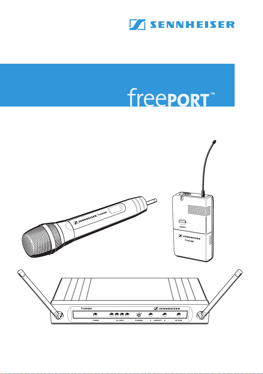
The freePORT systems ...................................................................... 3
Delivery includes .......................................................................... 4
EM 1 receiver ......................................................................................4
SK 2 bodypack transmitter .............................................................. 6
SKM 3 radio microphone .................................................................. 8
Setting up the system ......................................................................9
Care and maintenance ....................................................................10
If problems occur... ..................................................................... 11
Accessories and variants ................................................................11
Specifications of the freePORT systems ......................................12
Connector assignment ..............................................................13
Manufacturer declarations .............................................................14
Warranty .....................................................................................14
CE Declaration of Conformity ..................................................14
Batteries or rechargeable batteries .......................................14
WEEE Declaration .......................................................................14
Statements regarding the FCC and Industry Canada rules 14
Thank you for choosing Sennheiser!
We have designed this product to give you reliable operation over many
years. Over half a century of accumulated expertise in the design and
manufacture of high-quality electro-acoustic equipment have made
Sennheiser a world-leading company in this field.
Please take a few moments to read these instructions carefully, as we
want you to enjoy your new Sennheiser products quickly and to the
fullest.
1
Page 3

Important safety instructions
y Read this instruction manual.
y Keep this instruction manual in a safe place. Always include this
instruction manual when passing the device and the mains unit on to
third parties.
y Heed all warnings and follow all instructions.
y Clean the device and the mains unit only with a dry cloth.
y Refer all servicing to qualified service personnel. Servicing is required
if the device or the mains unit has been damaged in any way, liquid
has been spilled, objects have fallen inside, the device or the mains
unit has been exposed to rain or moisture, does not operate properly
or has been dropped.
y WARNING: To reduce the risk of fire or electric shock, do not expose
the device and the mains unit to rain or moisture. Do not place objects
filled with liquids, such as vases or coffee cups, on the device.
y Only use the supplied mains unit.
y Disconnect the mains connector from the wall socket
– to completely disconnect the device from the mains,
– during lightning storms or when unused for long periods of time.
y The mains unit must be operated only from the type of power source
specified in the chapter “Specifications of the freePORT systems”
(page 12).
y Ensure that the mains unit is
– always readily operable and easily accessible,
– properly plugged into the wall socket,
– only operated within the permissible temperature range,
– not covered or exposed to direct sunlight for longer periods of time
in order to prevent heat accumulation (see “Specifications of the
freePORT systems” on page 12).
y Do not block any ventilation openings. Install the device and the
mains unit in accordance with the manufacturer’s instructions.
y Do not install the device and the mains unit near any heat sources.
y Only use attachments/accessories specified by Sennheiser.
2
Page 4

The freePORT systems
Designed for different areas of application, the freePORT systems are
available in three variants.
y Presentation Set:
This system is ideal for presentation applications. The unobtrusive
ME 2 clip-on microphone is virtually invisible.
y Instrument Set:
This system is for connecting musical instruments (e.g. guitar) which
have a ¼” (6.3 mm) ja ck socke t directly to the bodypack transmitter.
y Vocal Set:
This system is ideal for vocal and speech applications.
Transmitters and receivers of the freePORT systems have four factorypreset frequencies for direct channel selection – ready for immediate
use after switch-on.
The freePORT systems are available in three UHF frequency ranges:
y Frequency range A: 719 to 721 MHz
y Frequency range B: 691 to 693 MHz
y Frequency range C: 742.5 to 744.5 MHz
y Frequency range E: 863 to 865 MHz
Notes:
Use of A, B and C frequency ranges must be licensed. Most EU
countries do not require licensing for use of frequency range E.
Frequency range B (691 to 693 MHz) is intended for use solely in
the USA and Canada.
Please be legal and observe the country-specific regulations of the
licensing authorities. Sennheiser are not responsible if you operate
illegally.
To avoid interfering with other users, the transmitter should be
switched off when not in use.
Features of the freePORT systems:
y Up to four transmission links per frequency range which can be
operated simultaneously
y Reliable transmission technology
y Diversity technology for minimizing dropouts in the reception
y Adjustable squelch for eliminating RF interference
y Rugged housings
y Crystal-clear reception due to dynamic processor
3
Page 5

Delivery includes
FreePORT systems
Stand mount
EM 1 receiver
SK 2
bodypack transmitter
SKM 3
radio microphone
Mains unit (NTxy)
ME 2
clip-on microphone
¼” (6.3 mm) jack cable
Instructions for use
Presentation Set XX XX X
Instrument Set XXXXX
Vocal Set XXX XX
EM 1 receiver
Operating controls
Antenna A
Operation indication, green LED (POWER)
쐋 RF level indication, four green LEDs
(RF LEVEL)
Channel selector switch CHANNEL (1 to 4)
Diversity indication, yellow LED A
(lights up if antenna is active)
Diversity indication, yellow LED B
(lights up if antenna is active)
AF PEAK, red LED (lights up if the audio
level is too high)
4
Antenna B
Audio output, XLR-3M socket, balanced
(AUDIO OUTPUT XLR BAL)
Audio output, ¼” (6.3 mm) jack socket,
unbalanced (AUDIO OUTPUT UNBAL)
Audio output level control (GAIN)
Squelch threshold control (SQUELCH)
DC socket for connection of mains unit
(DC 11–18 V IN, 100 mA)
Type plate
Serial number
Page 6

Connecting the receiver
왘 Insert the DC connector on the mains cable into the DC socket and
connect it to the mains. The green LED for operation indication
(POWER) lights up and the receiver is ready for operation.
왘 To deactivate the receiver, remove the mains plug from the mains
outlet.
Aligning the antennas
왘 Set up the antennas and align them upwards in a V-shape.
The LEDs A and B indicate which diversity section (i.e. which
antenna) is active.
Connecting the amplifier/mixing console
왘 Connect the amplifier/mixing console to the XLR-3M socket or
the ¼” (6.3 mm) jack socket .
왘 Use the GAIN control to adapt the level of the audio output to the
input of the amplifier or mixing console. The adjusted audio output
level is common for both sockets. If the level is adjusted too high,
the audio signal will be distorted. If, on the other hand, the level is
adjusted too low, this will result in an audio signal with high
background noise.
Selecting and changing a channel
You can change the channel on the receiver during running operation.
The receiver then immediately receives on the new channel.
왘 Use a small screwdriver to set the channel selector switch to the
desired channel. You can switch between four different channels
(“Selecting a channel”).
5
Page 7

SK 2 bodypack transmitter
Operating controls
ON/OFF button
Operation and battery status indication, red LED
쐋 Microphone/instrument input,
3.5 mm jack socket (lockable)
Antenna (can be screwed off)
Battery compartment cover
MIC/INST slide switch
Serial number
Channel selector switch CH (1 to 4)
Sensitivity control GAIN
Type plate
Belt clip
Inserting/replacing the battery
We recommend powering the bodypack transmitter by a 9 V PP3
alkaline battery (IEC 6 LR 61). If powered by a rechargeable 9 V battery,
the operating time will be drastically reduced.
왘 Open the battery compartment by first sliding the battery
compartment cover in the direction of the arrow. Then flip the
battery compartment cover open.
왘 Insert the battery as shown. Please observe correct polarity when
inserting the battery.
왘 Close the battery compartment.
Note:
When the red LED goes off during operation, you must replace
the battery as soon as possible.
6
Page 8

Connecting the microphone/instrument cable
The audio input is designed for the connection of both the ME 2 clip-on
microphone and instruments (e.g. guitars).
왘 Connect the 3.5 mm jack plug from the microphone/instrument
cable to the 3.5 mm jack socket 쐋.
왘 Check the setting of the MIC/INST slide switch which allows you
to switch between microphone and instrument operation. If
necessary, readjust the setting.
왘 Use the GAIN control to adjust the transmitter sensitivity so that
the receiver receives a good audio signal (no distortion and no
background noise).
Attaching and positioning the microphone
Use the microphone clip to attach the ME 2 clip-on microphone to
clothing (e.g. tie, lapel). Conduct the microphone cable so that noise due
to friction is avoided and make sure that the antenna and the cable do
not cross. The omni-directional microphone picks up sound equally from
all directions. However, it should be attached as close as possible to the
sound source.
Attaching the bodypack transmitter to clothing
왘 Use the supplied belt clip to attach the bodypack transmitter to
clothing. Make sure that the antenna is at least 1 cm away from the
body and is not kinked.
Switching the bodypack transmitter on/off
왘 Press the ON/OFF button to switch the bodypack transmitter on
or off. If the bodypack transmitter is switched on, the red LED
lights up.
Note:
Remove the battery when the transmitter will not be used for
extended periods of time.
Selecting and changing a channel
왘 Switch off the transmitter before you change the channel.
왘 Use a small screwdriver to set the channel selector switch to the
desired channel. You can switch between four different channels.
When you switch on the bodypack transmitter again, it will transmit
on the new channel (“Selecting a channel”).
7
Page 9

SKM 3 radio microphone
Operating control
Sound inlet basket
Locking ring of battery compartment
쐋 Body of radio microphone
Battery compartment (not visible from
outside)
Antenna (can be screwed off)
Operation and battery status indication,
red LED (POWER)
ON/OFF switch
Channel selector switch CH (1 to 4)
Type plate
Serial number
Note:
The microphone head of the radio microphone cannot be changed.
Inserting/replacing the battery
We recommend powering the radio microphone by a 9 V PP3 alkaline
battery (IEC 6 LR 61). If powered by a rechargeable 9 V battery, the
operating time will be drastically reduced.
왘 Turn the locking ring of the battery compartment in the direction
of the arrow.
왘 Pull the body of the radio microphone 쐋 in the direction of the
arrow as far as it will go.
왘 Insert the battery as shown. Please observe correct polarity when
inserting the battery.
왘 Close and lock the radio microphone.
Note:
When the red LED goes off during operation, you must replace
the battery as soon as possible.
8
Page 10

Switching the radio microphone on/off
왘 Use the ON/OFF switch to switch the radio microphone on or off.
If the radio microphone is switched on, the red LED lights up.
Note:
Remove the battery when the transmitter will not be used for
extended periods of time.
Selecting and changing a channel
왘 Switch off the radio microphone.
왘 Open the radio microphone (“Inserting/replacing the battery”).
왘 Use a small screwdriver to set the channel selector switch to the
desired channel. You can switch between four different channels
(“Selecting a channel”).
왘 Close and lock the radio microphone.
왘 Switch on the radio microphone again.
Sensitivity of the radio microphone
You can vary the bass reproduction by increasing/decreasing the
talking distance.
Setting up the system
Before starting transmission, do a soundcheck and set up the system as
follows:
Setting up the reception
The receiver’s four LEDs (RF LEVEL) 쐋 indicate the level of the received
RF signal. With the transmitter, walk up and down the transmission
area and check if the received RF signal is sufficient everywhere.
Reception is good if all four LEDs light up. Please observe the following:
y Transmission range depends to a large extent on location and can be
up to 100 m. Observe a minimum distance of 3 m between
transmitter and receiver. There should be a “free line of sight”
between transmitting and receiving antennas.
y Do not operate the system close to metal objects such as cross
members or reinforced-concrete walls. Computers or mobile phones
in direct proximity to the antenna will interfere with the reception.
y Each transmitter requires a receiver. When using several trans-
mission links simultaneously, make sure that all transmission links
operate on different channels.
9
Page 11

Adjusting the squelch threshold
Interference due to other transmission links can be eliminated as
follows:
왘 Switch off the transmitter. The receiver should no longer receive a
signal.
왘 If the receiver still receives a signal, use the SQUELCH control to
increase the squelch threshold so that the signal will no longer be
received. If the signal cannot be eliminated in this way, set the
transmitter and the receiver to a different channel.
왘 Switch on the transmitter again and check if the receiver receives
the transmitter signal.
Note:
If the squelch threshold is adjusted too high, the transmission range
will be reduced. Therefore, always adjust the squelch treshold to the
lowest possible setting.
Selecting a channel
Transmitters and receivers have four channels respectively with
intermodulation-free frequencies.
Note:
These frequencies are different to those in evolution systems and
freePORT systems should not be used together with evolution systems without great care.
10
왘 Always set the transmitter and the receiver to the same channel.
Adjusting the transmitter sensitivity
왘 Use the GAIN control on the SK 2 bodypack transmitter to adjust
the sensitivity so that even during the loudest passages the
AF PEAK LED on the EM 1 receiver does not light up.
Care and maintenance
Use a slightly damp cloth to clean the units from time to time.
Note:
Do not use any cleansing agents or solvents.
To clean the SKM 3’s sound inlet basket:
왘 Unscrew the sound inlet basket (turn counterclockwise) and
remove it.
왘 Remove the foam insert and use a slightly damp cloth to clean the
sound inlet basket.
왘 Reinsert the dry foam insert, replace the sound inlet basket on the
SKM 3 and screw it tight.
Page 12

If problems occur...
Problem Possible cause Possible solution
No operation indication Battery is flat Replace the battery
No mains connection (receiver) Check the connections of the mains
unit
No RF signal Transmitter and receiver are not on
the same channel
Transmitter is out of range Reduce the distance between
RF signal available,
no audio signal
Audio signal has a high
level of background
noise or is distorted
Receiver’s squelch threshold is
adjusted too high
Transmitter sensitivity is adjusted
too low or too high
The MIC/INST slide switch on
the SK 2 transmitter is not set
correctly
Receiver’s audio output level is
adjusted too low or too high
Annoying noises When the battery is almost flat,
the transmitter may produce
annoying noises which can
damage the PA system.
Set transmitter and receiver to
the same channel
transmitter and receiver
See “Adjusting the squelch
threshold” on page 10
See “Connecting the microphone/
instrument cable” on page 7
See “Connecting the amplifier/
mixing console” on page 5
After the LED has gone off,
replace the battery as soon as
possible or switch the transmitter
off.
Accessories and variants
04839 MZW 1 Wind- and popshield for SKM 3
76670 MZQ 1 Microphone clamp for SKM 3
05018 ME 2 Clip-on microphone for SK 2, pre-polarized condenser microphone, omni-
directional
05019 ME 3 Headmic for SK 2, pre-polarized condenser microphone, super-cardioid
05020 ME 4 Clip-on microphone for SK 2, pre-polarized condenser microphone, cardioid
512889 CI1-fp Guitar cable
11
Page 13

Specifications of the freePORT systems
System characteristics
Transmission/receiving
frequencies
Switching bandwidth 2 MHz
Signal-to-noise ratio
THD (1 kHz)
Temperature range –10 bis +45 °C / 95 relative humidity
Individual components
Power supply 12V DC
Operating time
(with alkaline battery)
Frequency response – 60...16,000 Hz ± 3 dB 80...16,000 Hz ± 3 dB
RF output power (-3 dB) – 10 mW 10 mW
AF output voltage
¼’’ (6.3 mm) jack socket (unbal.):
XLR socket (balanced):
Dimensions in mm approx. 35 x 213 x 98 approx. 60 x 100 x 30
Weight approx. 570 g approx. 90 g approx. 210 g
Transducer principle – – dynamic
Pick-up pattern––cardioid
ME 2 clip-on microphone
Transducer principle
Pick-up pattern
4 UHF transmission/receiving frequencies
Range A: 719 to 721 MHz
(719.15 – 719.75 – 720.15 – 720.85 MHz)
Range B: 691 to 693 MHz
(691.00 – 691.40 – 692.35 – 692.90 MHz)
Range C : 742.5 to 744.5 MHz
(742.65 – 743.35 – 743.85 – 744.45 MHz)
Range E: 863 to 865 MHz (863.10 – 863.70 – 864.10 – 864.90 MHz)
>
95 dB(A)
<
1 %
EM 1
receiver
/100 mA 9 V PP3 battery 9 V PP3 battery
NOM
– approx. 10 hrs approx. 10 hrs
max. +10 dB
max. +16 dB
pre-polarized condenser
omni-directional
u
u
SK 2
bodypack transmitter
––
(with belt clip)
SKM 3
radio microphone
approx. 285;
∅ approx. 35 x 50
12
Page 14

Type approvals
Instr./MIC
NC/GND
In compliance with EMC EN 301489-1/-9
Radio EN 301357-1/-2
Safety EN 60065
Also approved by
Industry Canada RSS 210, IC: 2099A
SKM3/EM1-A/-C IC: 2099A-FPSKMEM
SKM3/EM1-B IC: 2099A-FPSKMEMB
SK2-A/-C IC: 2099A-FPSK
SK2-B IC: 2099A-FPSKB
FCC-Part 74 SK2-A/-C FCC ID: DMOB1FPXD
SK2-B FCC ID: DMOB2FPSK
SKM3-A/-C FCC ID: DMOH1FPXD
SKM3-B FCC ID: DMOH2FPSKM
Transmitters that operate in the frequency range E (863 – 865 MHz) can be used licence-free in the
following countries:
AT, BA, BE, CH, CY, CZ, DE, DK, EE, ES, FI, FR, GB, GR, HU, IE, IS, IT, LI, LT, LU, ME, MK, MT, NL, NO, PL, PT, RO,
RS, RU, SE, SI, SK, TR, UA.
Transmitters that operate in frequency range A (719 – 721 MHz),
C (742.5 – 744.5 MHz)
must only be used with an appropriate radio transmission licence. Frequency
B (691–693 MHz)
or frequency range
range B is intended for use solely in the USA and Canada.
Frequency range Presentation Set Instrument Set Vocal Set
691 – 693 MHz:
with US mains unit freePort fp 12-B-US freePort fp 72-B-US freePort fp 35-B-US
– 721 MHz:
719
with US mains unit freePort fp 12-A-US freePort fp 72-A-US freePort fp 35-A-US
742.5
– 744.5 MHz:
with EU mains unit freePort fp 12-C-EU freePort fp 72-C-EU freePort fp 35-C-EU
with US mains unit freePort fp 12-C-US freePort fp 72-C-US freePort fp 35-C-US
863
– 865 MHz:
with EU mains unit freePort fp 12-E-EU freePort fp 72-E-EU freePort fp 35-E-EU
with UK mains unit freePort fp 12-E-UK freePort fp 72-E-UK freePort fp 35-E-UK
Connector assignment
EM 1:
¼’’ (6.3 mm) stereo
jack plug,unbalanced
NC/GND
EM 1:
¼’’ (6.3 mm) mono
jack plug,unbalanced
EM 1:
XLR-3F connector,
balanced
21
+
3
EM 1:
DC connector for
power supply
SK 2:
3.5 mm jack plug
13
Page 15

Manufacturer declarations
0682
Warranty
Sennheiser electronic GmbH & Co. KG gives a warranty of 24 months on this product. For the current warranty conditions, please visit our web site at www.sennheiser.com or contact your Sennheiser partner.
CE Declaration of Conformity
This equipment is in compliance with the essential requirements and other relevant provisions of Directives 1999/
5/EC, 2004/108/EC or 2006/95/EC. The declaration is available on the internet site at www.sennheiser.com.
Before putting the device into operation, please observe the respective country-specific regulations!
Batteries or rechargeable batteries
The supplied batteries or rechargeable batteries can be recycled. Please dispose of them as special
waste or return them to your specialist dealer. In order to protect the environment, only dispose of
exhausted batteries.
WEEE Declaration
Your Sennheiser product was developed and manufactured with highquality materials and components
which can be recycled and/or reused. This symbol indicates that electrical and electronic equipment
must be disposed of separately from normal waste at the end of its operational lifetime.
Please dispose of this product by bringing it to your local collection point or recycling centre for such
equipment. This will help to protect the environment in which we all live.
Statements regarding the FCC and Industry Canada rules
This device complies with Part 15 of the FCC Rules and with RSS-210 of Industry Canada. Operation is subject
to the following two conditions: (1) this device may not cause harmful interference, and (2) this device must
accept any interference received, including interference that may cause undesired operation.
This equipment has been tested and found to comply with the limits for a Class B digital device, pursuant to
Part 15 of the FCC Rules. These limits are designed to provide reasonable protection against harmful interference in a residential installation. This equipment generates, uses and can radiate radio frequency energy
and, if not installed and used in accordance with the instructions, may cause harmful interference to radio
communications. However, there is no guarantee that interference will not occur in a particular installation.
If this equipment does cause harmful interference to radio or television reception, which can be determined
by turning the equipment off and on, the user is encouraged to try to correct the interference by one or more
of the following measures:
y Reorient or relocate the receiving antenna.
y Increase the separation between the equipment and receiver.
y Connect the equipment into an outlet on a circuit different from that to which the receiver is connected.
y Consult the dealer or an experienced radio/TV technician for help.
This class B digital apparatus complies with the Canadian ICES-003 Cet appareil numérique de la classe B est
conforme à la norme NMB-003 du Canada.
Changes or modifications made to this equipment not expressly approved by Sennheiser electronic Corp.
may void the FCC authorization to operate this equipment.
Before putting the device into operation, please observe the respective country-specific regulations!
14
Page 16

Sennheiser electronic GmbH & Co. KG
Am Labor 1
30900 Wedemark, Germany
www.sennheiser.com
Printed in Taiwan Publ. 08/08 514013/ A05
 Loading...