

Sennheiser eW300 Gw, em 300 g2 Instructions For Use Manual
Instructions for use
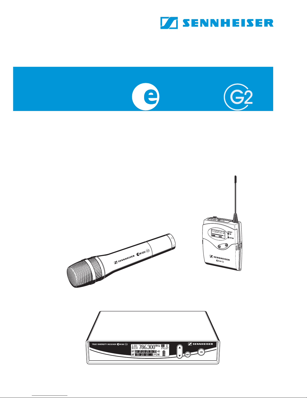
W 300

48
Thank you for choosing Sennheiser!
We have designed this product to give you reliable operation over many
years. Over half a century of accumulated expertise in the design and
manufacture of high-quality electro-acoustic equipment have made
Sennheiser a world-leading company in this field.
Please take a few moments to read these instructions carefully, as we want
you to enjoy your new Sennheiser products quickly and to the fullest.

49
Contents
The evolution wireless series ew 300 G2 ........................................................... 50
The channel bank system ............................................................................................. 50
Safety instructions ................................................................................................. 51
System variants ...................................................................................................... 51
Overview of operating controls ........................................................................... 52
EM 300 G2 rack-mount receiver .................................................................................. 52
SK 300 G2 bodypack transmitter ................................................................................ 53
SKM 300 G2 radiomicrophone ..................................................................................... 54
Indications and displays on the receiver ................................................................... 55
Indications and displays on the transmitters ........................................................... 56
Preparing the components for use ..................................................................... 58
EM 300 G2 rack-mount receiver .................................................................................. 58
SK 300 G2 bodypack transmitter ................................................................................ 61
SKM 300 G2 radiomicrophone ..................................................................................... 63
Using the components .......................................................................................... 64
Switching the components on/off .............................................................................. 64
Muting the transmitters ............................................................................................... 65
Activating/deactivating the lock mode ..................................................................... 65
The operating menu ............................................................................................... 66
The buttons ..................................................................................................................... 66
Overview of menus ......................................................................................................... 66
Working with the operating menu ............................................................................. 67
Operating menu of the receiver ................................................................................... 69
Operating menu of the transmitters .......................................................................... 72
Adjustment tips for the operating menu .......................................................... 74
Switching between channel banks ............................................................................. 74
Switching between the channels in a channel bank ............................................... 74
Selecting the frequencies to be stored in the channel bank “U” .......................... 74
Scanning the channel banks for free channels (EM 300 G2 only) ........................ 75
Multi-channel operation ................................................................................................ 76
Adjusting the sensitivity (transmitters only) .......................................................... 76
Adjusting the audio output level (EM 300 G2 only) ............................................... 77
Adjusting the squelch threshold (EM 300 G2 only) ................................................ 77
Selecting the standard display .................................................................................... 78
Entering a name .............................................................................................................. 79
Loading the factory-preset default settings ............................................................. 79
Activating/deactivating the pilot tone transmission or pilot tone evaluation .. 79
Activating/deactivating the lock mode ..................................................................... 80
Adjusting the contrast of the graphic display (EM 300 G2 only) ......................... 80
Exiting the operating menu .......................................................................................... 80
If problems occur... ................................................................................................. 81
Error checklist .............................................................................................. 81
Recommendations and tips .......................................................................................... 82
Care and maintenance ........................................................................................... 83
Additional information .......................................................................................... 84
HDX noise reduction ..................................................................................... 84
Wireless transmission systems ................................................................................... 84
Squelch ............................................................................................................................. 85
Diversity reception ......................................................................................................... 85
Specifications .......................................................................................................... 86
Connector assignment ................................................................................................... 87
Polar diagrams and frequency response curves of
microphones/microphone heads ................................................................................. 88
Accessories .............................................................................................................. 89
50
The evolution wireless series ew 300 G2
With the evolution wireless series ew 300 G2, Sennheiser offers musicians, video
and sound amateurs high-quality state-of-the-art RF transmission systems with
a high level of operational reliability and ease of use. Transmitters and receivers
permit wireless transmission with studio-quality sound. The excellent
transmission reliability of the ew 300 G2 series is based on the use of
y further optimized PLL synthesizer and microprocessor technology,
y the HDX noise reduction system,
y the pilot tone squelch control,
y the true diversity technology (rack-mount receiver only),
y and the scan function for scanning the channel banks for free channels.
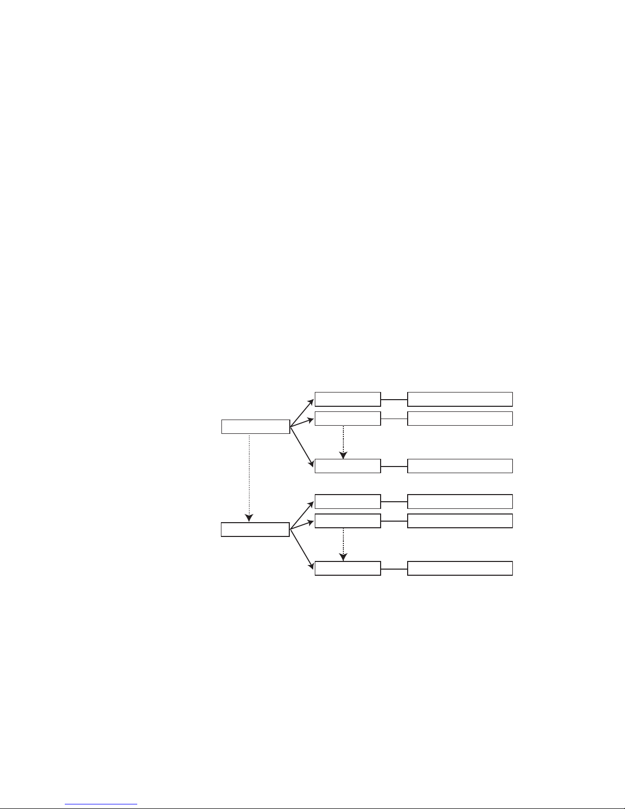
The channel bank system
The ew 300 G2 systems are available in five UHF frequency ranges with 1440
transmission/receiving frequencies per frequency range. Please note:
Frequency usage is different for each country. Your Sennheiser agent will
have all the necessary details on the available legal frequencies for your area.
Range A: 518 to 554 MHz
Range B: 626 to 662 MHz
Range C: 740 to 776 MHz
Range D: 786 to 822 MHz
Range E: 830 to 866 MHz
Transmitters and receivers have nine channel banks with eight switchable
channels each.
The channel banks “1” to “8” have eight switchable channels that are
factory-preset to a transmission/receiving frequency (see enclosed
frequency table). These transmission/receiving frequencies cannot be
changed but have been preset so that e.g. country-specific regulations on
frequency usage are taken into account. The channel bank “U” (user bank)
has eight switchable channels to store your selection out of 1440
transmission/receiving frequencies that are freely selectable within the
preset frequency range.
An advantage of the factory-preset frequencies is that
y the systems are ready for immediate use after switch-on,
y several systems can be operated simultaneously on the preset channels
without causing intermodulation interference.
channel bank 1...8
channel 1
channel 2
channel 8
preset frequency
preset frequency
preset frequency
channel bank U
channel 1
channel 2
channel 8
freely selectable frequency
freely selectable frequency
freely selectable frequency
51
Safety instructions
Never open electronic units! If units are opened by customers in breach of this
instruction, the warranty becomes null and void.
Keep the units away from central heating radiators and electric heaters.
Never expose them to direct sunlight.
Use the units in dry rooms only.
Use a damp cloth for cleaning the units. Do not use any cleansing agents or
solvents.
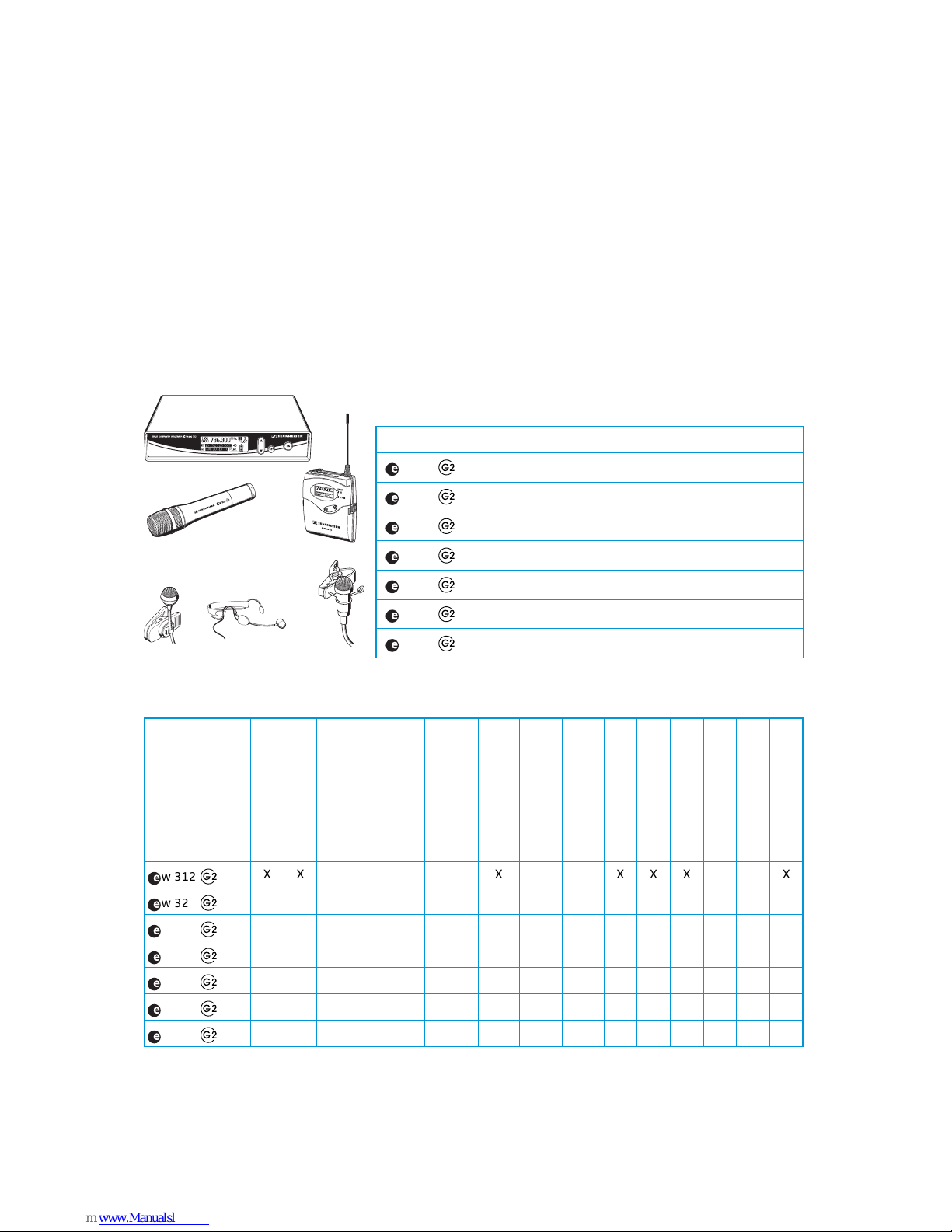
System variants
Areas of application
Delivery includes
EM 300 G2
ME 2
ME 4
ME 3 headmic
SKM 300 G2
SK 300 G2
System Areas of application
w312
Theater, presentation (omni-directional)
w322
Theater, presentation (high feedback rejection)
w352
Sports (aerobic), vocals
w372
Instruments
w335
Speech, vocals
w345
Vocals (high feedback rejection)
w365
Vocals, presentation (high feedback rejection)
/
/
/
/
/
/
/
w 312
XX X XXX X
w 322
XX X XXX X
w 352
XX X xXX X
w 372
XX XXX XX
w 335
X X XXXX X
w 345
X X XXXX X
w 365
X X XXXX X
System
EM 300 G2
SK 300 G2
SKM 300 G2 with
MD 835 mic head
(dynamic, cardioid)
SKM 300 G2 with
MD 845 mic head
(dynamic, super-cardioid)
SKM 300 G2 with
ME 865 mic head
(condenser, super-cardioid)
ME 2 c
li
p-on m
i
crop
h
one
(condenser, omni)
ME 3
h
ea
d
m
i
c
(condenser, super-cardioid)
ME 4 c
li
p-on m
i
crop
h
one
(condenser, cardioid)
NT 2-1 mains unit
2 batteries
2 telescopic antennnas
Microphone clamp
Instrument cable
Instructions for use
/
/
/
/
/
/
/
52
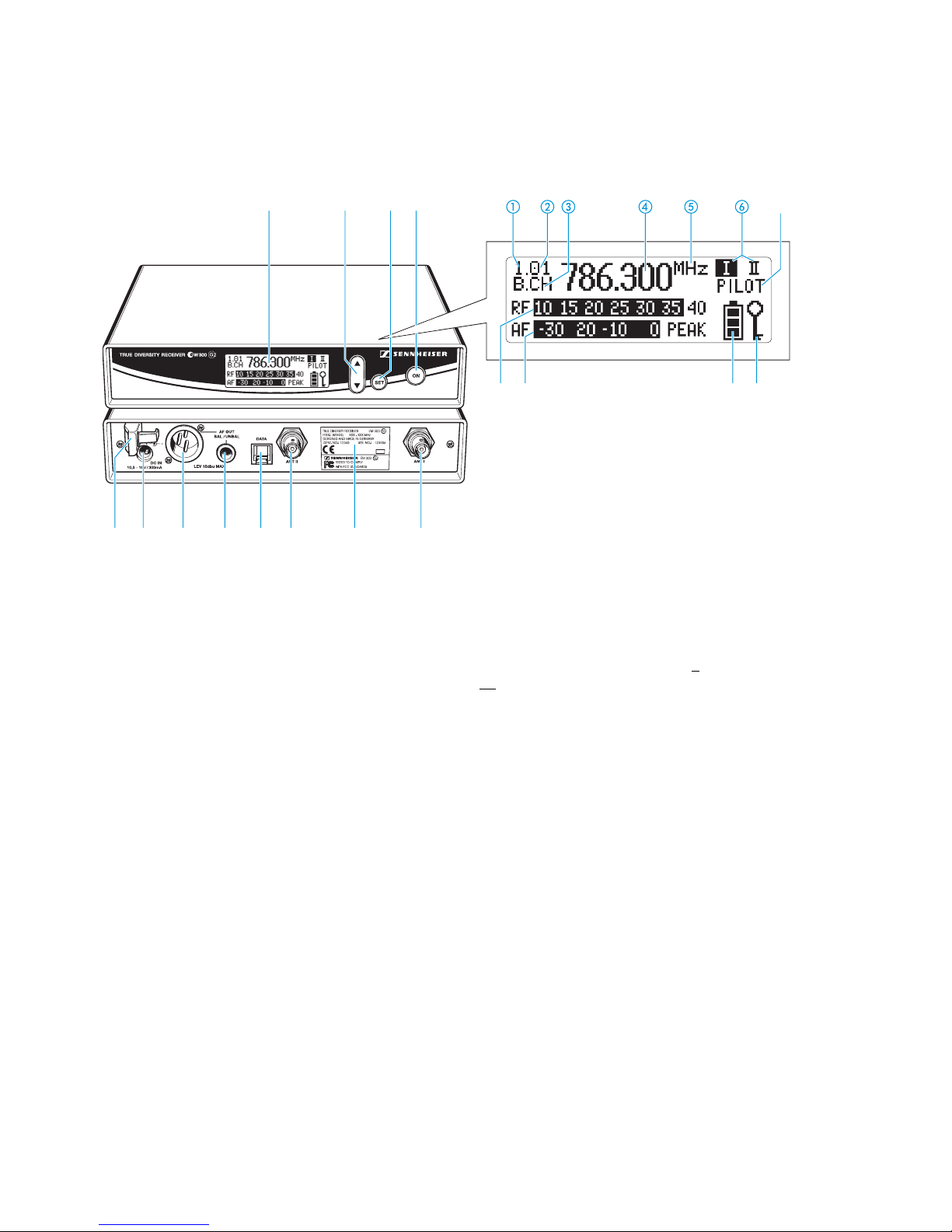
Overview of operating controls
EM 300 G2 rack-mount receiver
Operating controls Graphic display panel
Graphic display, backlit
/ rocker button (DOWN/UP), backlit
SET button, backlit
ON button, backlit
(serves as the ESC (cancel) key in the
operating menu)
Cable grip for power supply DC cable
DC socket for connection of mains unit (DC IN)
Audio output (AF OUT BAL),
XLR-3M socket, balanced
Audio output (AF OUT UNBAL),
¼” (6.3 mm) jack socket, unbalanced
Service interface (DATA)
Antenna input II (ANT II), BNC socket
Type plate
Antenna input I (ANT I), BNC socket
Display for the current channel bank “1...8, U”
Display for the current channel number “1...8”
“B.CH“ – abbreviation for channel B
ank and
CH
annel number
Alphanumeric display
“MHz“ – appears when the frequency is displayed
Diversity display
(antenna I or antenna II active)
“PILOT” display
(pilot tone evaluation is activated)
Level display for received RF signal “RF”
Level display for received audio signal “AF”,
with “PEAK“ warning
4-step transmitter battery status display
Lock mode icon
(lock mode is activated)
Note:
For further illustrations and examples of the different
standard displays, please refer to the section
“Selecting the standard display” on page 78.
53
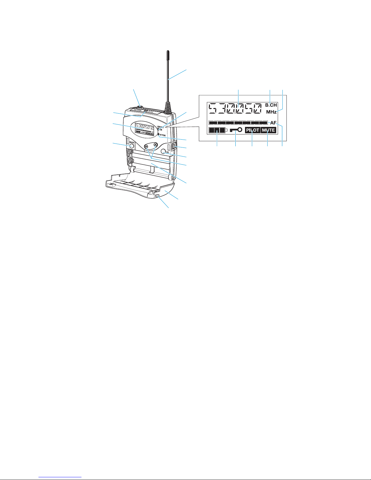
SK 300 G2 bodypack transmitter
Operating controls LC display panel
Microphone/line input (MIC/LINE),
3.5 mm jack socket
Antenna
Red LED for operation and
battery status indication (ON/LOW BAT)
Yellow LED for audio peak (AF PEAK)
Charging contacts
SET button
/ rocker button (DOWN/UP)
Battery compartment
Battery compartment cover
Unlocking button
ON/OFF button
(serves as the ESC (cancel) key in the
operating menu)
LC display
MUTE switch
Alphanumeric display
“B.CH“ – appears when the channel bank and
the channel number are displayed
“MHz“ – appears when the frequency is displayed
4-step battery status display
Lock mode icon
(lock mode is activated)
“PILOT” display
(pilot tone transmission is activated)
“MUTE” display
(audio input is muted)
7-step level display for audio signal “AF”
54
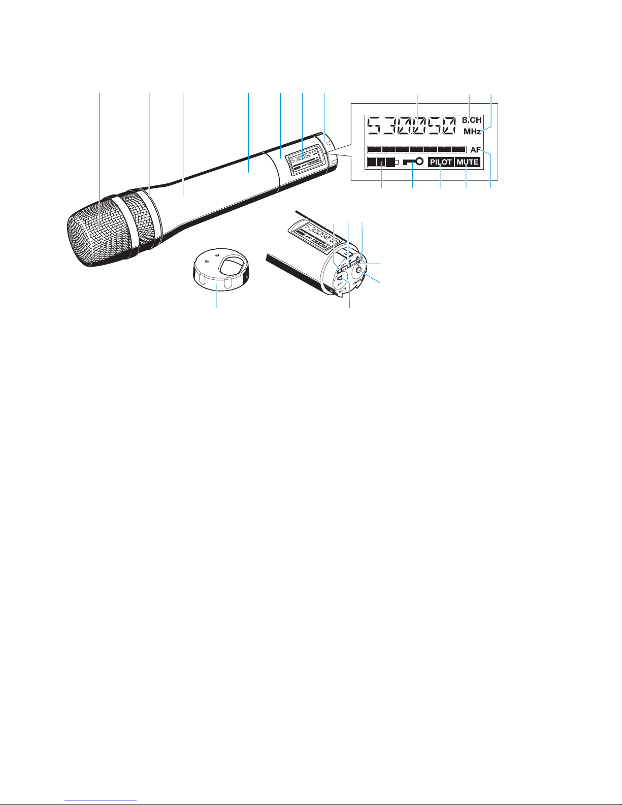
SKM 300 G2 radiomicrophone
Operating controls LC display panel
Sound inlet basket
Color-coded identification ring for
microphone heads
green: MD 835 microphone head
blue: MD 845 microphone head
red: ME 865 microphone head
Body of radiomicrophone
Battery compartment (not visible from outside)
Display section
LC display
Turnable protective cap for operating controls
(shown removed)
The following operating controls become accessible
in turn by turning the protective cap:
SET button
button (DOWN)
button (UP)
Red LED for operation and
battery status indication (ON/LOW BAT)
ON/OFF button
(serves as the ESC (cancel) key in the
operating menu)
MUTE switch
Alphanumeric display
“B.CH“ – appears when the channel bank and
the channel number are displayed
“MHz“ – appears when the frequency is displayed
4-step battery status display
Lock mode icon
(lock mode is activated)
“PILOT” display
(pilot tone transmission is activated)
“MUTE” display
(audio input is muted)
7-step level display for audio signal “AF”

55
Indications and displays on the receiver
Transmitter battery status indication
The 4-step transmitter battery status display on the receiver display panel
provides information on the transmitter’s remaining battery/accupack
BA 2015 capacity:
“MUTE” display
The “MUTE” display appears on the display panel and the backlighting of
the standard display switches from green to red. In addition, the text “MUTE”
flashes in alternation with the standard display when
y the RF signal of the received transmitter is too weak,
y the received transmitter has been muted (with the pilot tone transmission
or evaluation activated).
Modulation display
The level display for audio signal “AF” shows the modulation of the received
transmitter.
When the transmitter’s audio input level is excessively high (AF peak), the
receiver’s level display for audio signal “AF” shows full deflection.
When the transmitter is overmodulated frequently or for an extended period
of time, the text “PEAK” (backlit in red) flashes in alternation with the
standard display.
“PILOT” display
The “PILOT” display lights up when the pilot tone evaluation is activated
(see “Activating/deactivating the pilot tone transmission or pilot tone
evaluation“ on page 79).
3 segments: capacity approx. 100 %
2 segments: capacity approx. 70 %
1 segment: capacity approx. 30 %
Battery icon flashing: LOW BAT
In addition, the text “LOW BAT” (backlit in red)
flashes in alternation with the standard display.
56
Diversity display
The EM 300 G2 receiver operates on the true diversity principle (see
“Diversity reception“ on page 85).
The diversity display indicates whether diversity section I (i.e. antenna 1)
or diversity section II (i.e. antenna 2) is active.
Button backlighting
In standby operation, the ON button is backlit in red. When the receiver is
switched on, the SET button and the / button are additionally
backlit in green.
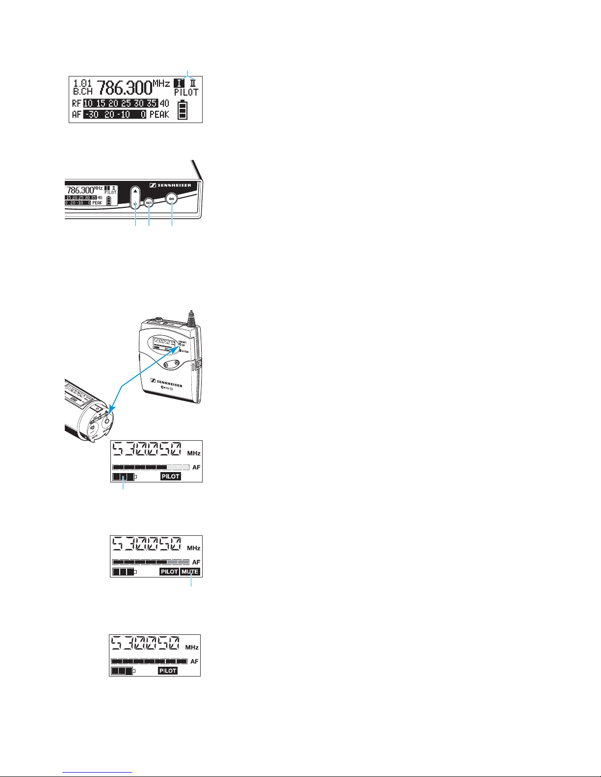
Indications and displays on the transmitters
Operation and battery status indication
The red LED (LOW BAT/ON) provides information on the current operating
state of the transmitter:
Red LED lit up: The transmitter is switched on and the capacity of the
batteries/accupack BA 2015 is sufficient.
Red LED flashing: The batteries are/the accupack BA 2015 is going flat
(LOW BAT)!
In addition, the 4-step battery status display on the display panel provides
information on the remaining battery/accupack BA 2015 capacity.
“MUTE” display
The “MUTE” display appears on the display panel when the transmitter is
muted (see “Muting the transmitters“ on page 65).
Modulation display
The level display for audio signal “AF” shows the modulation of the
transmitter. When the transmitter’s audio input level is excessively high, the
level display for audio signal “AF” shows full deflection.
3 segments: capacity approx. 100 %
2 segments: capacity approx. 70 %
1 segment: capacity approx. 30 %
Battery icon flashing: LOW BAT

57
AF peak indication (SK 300 G2 only)
The yellow LED (AF PEAK) at the front of the SK 300 G2 lights up when the
audio input level is excessively high (AF peak) and overmodulates the
transmitter. At the same time, the 7-step level display for audio signal “AF”
shows full deflection for the duration of the overmodulation.
“PILOT” display
The “PILOT” display lights up when the pilot tone evaluation is activated.
(see “Activating/deactivating the pilot tone transmission or pilot tone
evaluation“ on page 79).
Display backlighting
After pressing a button, the display remains backlit for approx. 15 seconds.
58
Preparing the components for use
EM 300 G2 rack-mount receiver
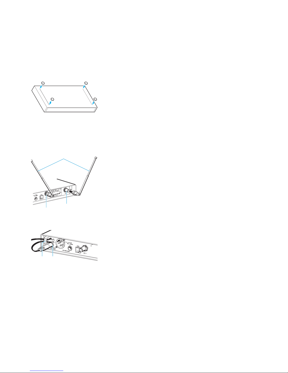
Mounting the receiver feet
To ensure that the receiver cannot slip on the surface on which it is placed,
four self-adhesive soft rubber feet are supplied.
Ensure that the base of the receiver is clean before mounting the rubber
feet.
Fix the rubber feet to the base of the receiver by peeling of the safety
paper and fitting them as shown in the digram on the left.
Attention!
Some furniture surfaces have been treated with varnish, polish or
synthetics which might cause stains when they come into contact with
other synthetics. Despite a thorough testing of the synthetics used by us,
we cannot rule out the possibility of staining.
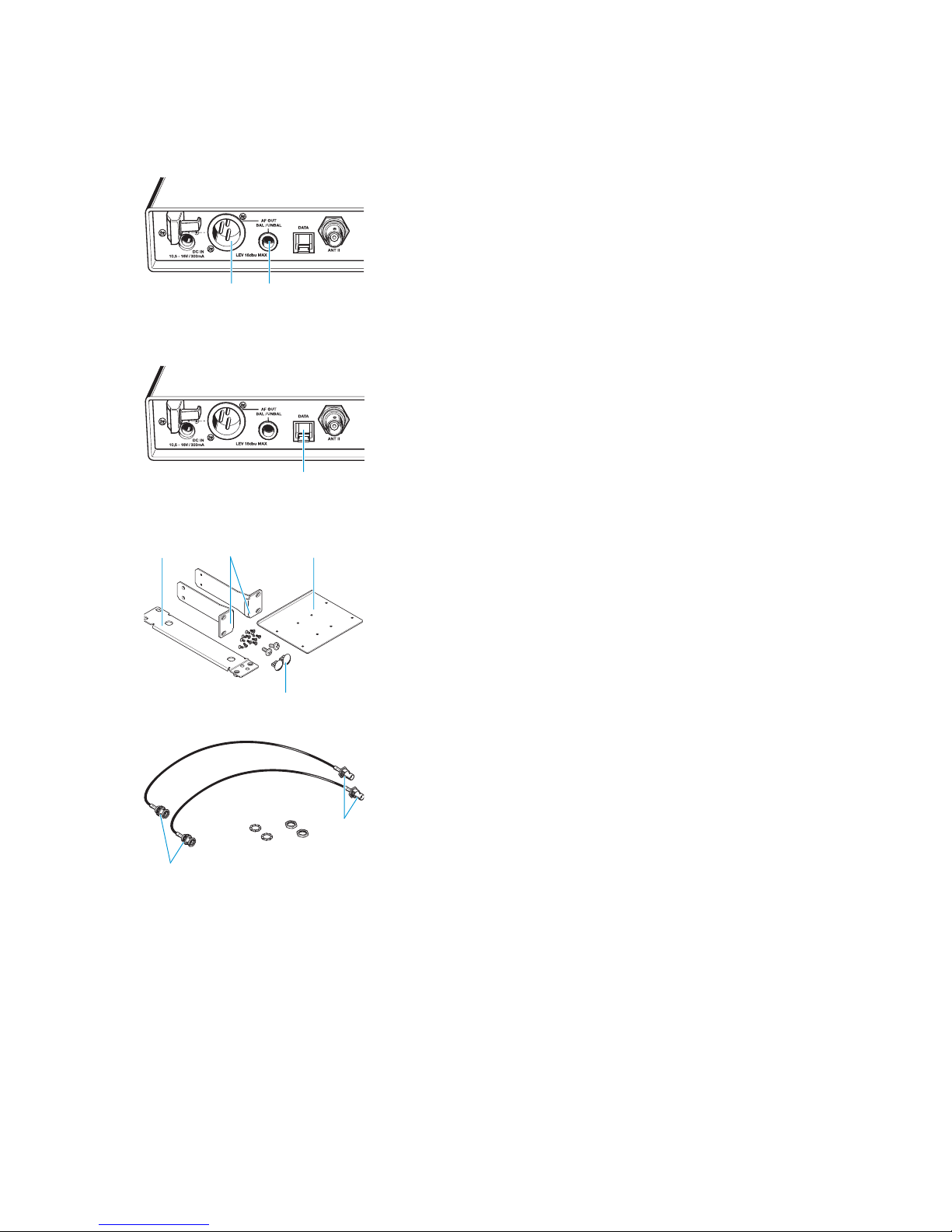
Connecting the antennas
The supplied telescopic antennas can be mounted quickly and easily to the
rear of the receiver and are suitable for all applications where – good
reception conditions provided – a wireless transmission system is to be used
without a large amount of installation work.
Connect the telescopic antennas to the BNC sockets and at the
rear of the receiver.
Pull the telescopic antennas out and align the upwards in a V-shape.
Use remote antennas when the receiver position is not the best antenna
position for optimum reception. These are available as accessories.
Connecting the mains unit
The EM 300 G2 is powered via a mains unit.
Pass the cable through the cable grip .
Insert the DC connector on the mains cable into the DC socket .
59
Connecting the amplifier/mixing console
The EM 300 G2’s audio outputs are available as an XLR-3M socket and a
¼” (6.3 mm) jack socket , allowing you to simultaneously connect two
units (e.g. amplifier, mixing console). The adjusted audio output level is
common for both sockets.
Connect the amplifier/mixing console to the XLR-3M socket or the
¼” (6.3 mm) jack socket .
For detailed information on balanced and unbalanced connection, please
refer to the section “Connector assignment” on page 87.
Via the operating menu, adapt the level of the audio output (AF OUT) to
the input of the amplifier or mixing console (see “Adjusting the audio
output level (EM 300 G2 only)“ on page 77).
Service interface
The service interface is only required for servicing purposes.
19” rack adapter and antenna mount
For mounting one or two receivers into a 19” rack, you require the GA 2 rack
adapter (available as an accessory). The GA 2 rack adapter consists of:
y 2 rack mount “ears”
y 1 connecting bar
y 1 connecting plate
y 2 covering plugs for antenna holes
y 12 recessed head screws M 3x6
y 2 recessed head screws M 6x10
When mounting only one receiver into a rack, you can use the AM 2 antenna
mount (available as an accessory) to mount the transmitter’s antenna
connection to the front of the GA 2 rack adapter. The AM 2 antenna mount
consists of:
y 2 BNC extension cables (screw-in BNC socket ! to BNC connector ")
y 2 plains washers
y 2 nuts
# $
%
"
!
60
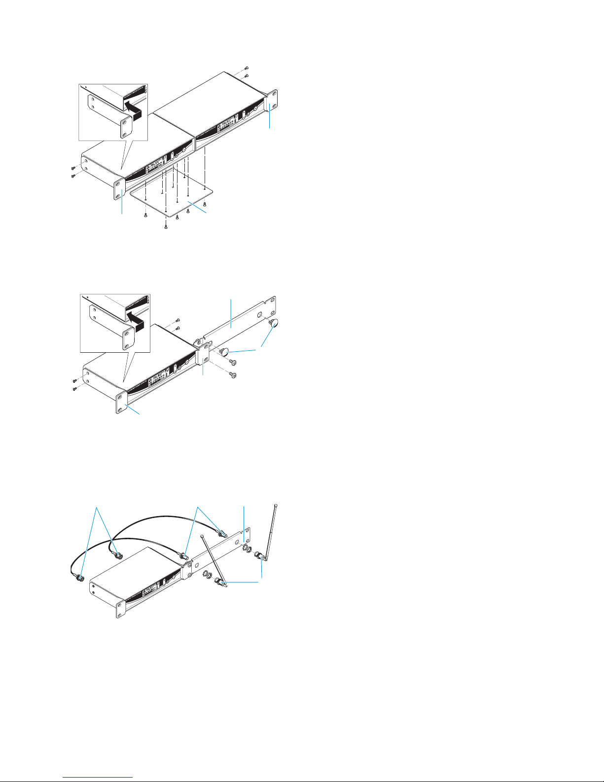
To mount two EM 300 G2 into a rack:
Place the two receivers side by side onto a flat
surface, their bottom sides facing upwards.
Align the connecting plate over the holes in the
bottom sides of the receivers.
Secure the connecting plate to the receivers
using eight of the supplied recessed head screws
(M 3x6).
Hook the two rack mount “ears” to the front
panels of the receivers.
Secure the rack mount “ears” to the receivers using
two of the supplied recessed head screws (M 3x6)
respectively.
Slide the receivers into a 19” rack.
Screw the rack mount “ears” tight.
When mounting only one receiver into a rack, use the
connecting bar instead of the second receiver.
Hook the two rack mount “ears” to the front
panel of the receiver.
Secure the rack mount “ears” to the receiver using
two of the supplied recessed head screws (M 3x6)
respectively.
Secure the connecting bar to one of the rack
mount “ears” using two of the supplied recessed
head screws (M 6x10).
If you are not front mounting the antennas, insert
the two covering plugs into the antenna holes of
the connecting bar.
Slide the receiver into a 19” rack and screw the rack
mount “ears” tight.
To mount the receiver’s antenna connection to the
front of the GA 2 rack adapter using the AM 2 antenna
mount:
Screw the two BNC sockets ! of the BNC extension
cables to the connecting bar using the supplied
plain washers and nuts.
Connect the two BNC connectors " to the BNC
sockets and at the rear of the receiver.
Slide the receiver into a 19” rack.
Screw the rack mount “ears” tight.
Connect the two telescopic antennas to the two
BNC sockets !.
Pull the telescopic antennas out and align them
upwards in a V-shape.
!
"
 Loading...