

Sennheiser EK IEM G4 Users Manual
Sennheiser electronic GmbH & Co. KG
Am Labor 1, 30900 Wedemark, Germany, www.sennheiser.com
ew IEM G4 - v1.1
evolution wireless G4
IEM series
Instruction Manual

Overview 5
ew IEM G4 series products 6
EK IEM G4 stereo diversity receiver 7
SR IEM G4 stereo transmitter 8
Accessories 9
Earphones 9
IE 4 9
Rechargeable battery and charger 10
BA 2015 rechargeable battery 10
L 2015 charger 10
Accessories for rack mounting 11
GA 3 rack mount kit 11
AM 2 antenna front mounting kit 11
Antennas and accessories 12
Omni-directional antennas 12
Directional antennas 12
Antenna combiner 12
Antenna cables 12
The frequency bank system 13
Installing and starting up ew IEM G4 series devices
14
Installing the EK IEM G4 15
Inserting and removing the batteries/rechargeable batteries 15
Battery status 16
Connecting earphones to the EK IEM G4 17
Attaching the diversity receiver to your clothing 18
Installing the SR IEM G4 19
Connectors on the rear of the device 19
SR IEM G4 rear side product overview 19
Connecting/disconnecting the SR IEM G4 with/from the
power supply 20
Creating a data network 21
Connecting audio signals 22
Mono 22
Stereo 23
Daisy chaining audio signals 24
Connecting antennas 25
Installing the SR IEM G4 in a rack 26
Mounting a single transmitter in a rack 27
Mounting two receivers side by side in a rack 29
Installing the AC 41 30
Connectors on the rear of the device 30
Connecting/disconnecting the AC 41 to/from the power
supply system 31
Connecting the AC 41 with transmitters 32
Connecting antennas 34
Installing the AC 41 in a rack 35
Mounting a single antenna combiner in a rack 36
Mounting two antenna combiners side by side in a rack
1

37
Using ew IEM G4 series devices 38
Using the EK IEM G4 40
Operating elements of the EK IEM G4 diversity receiver
40
EK IEM G4 product overview 40
Switching the EK IEM G4 on and off 42
Lock-off function 43
Displays on the EK IEM G4 display panel 44
Buttons for navigating through the menu 44
Home screen 46
Frequency/Name standard display 46
Bank/Frequency/Limiter standard display 47
Frequency/High Boost standard display 48
Setting options in the menu 49
Menu structure 51
Squelch menu item 52
Easy Setup menu item 54
Scan New List 54
Current List 54
Reset 55
Performing multi-channel frequency setup 55
Frequency Preset menu item 59
Name menu item 60
Balance menu item 60
Mode menu item 61
High Boost menu item 62
Auto Lock menu item 63
Advanced menu item 64
Advanced -> Tune menu item 65
Only adjusting the frequency 65
Setting the channel and frequency 65
Advanced -> Limiter menu item 66
Advanced -> Volume Boost menu item 67
Advanced -> LCD Contrast menu item 67
Advanced -> Engineer Mode menu item 68
Profiles List 68
Load Profiles 69
Advanced -> Reset menu item 70
Advanced -> Software Revision menu item 70
Using the SR IEM G4 71
Operating elements of the SR IEM G4 transmitter 71
Switching the SR IEM G4 on and off 72
Using the headphone output 73
Configuring the audio channels (mono/stereo) 74
Deactivating the RF signal (RF mute) 75
Lock-off function 76
Displays on the SR IEM G4 display panel 77
Buttons for navigating the SR IEM G4 menu 79
Navigating through the menu 79
Making changes in a menu item 79
2

Setting options in the menu 80
Sensitivity menu item 81
Mode menu item 81
Easy Setup menu item 82
Frequency Preset menu item 82
Name menu item 83
Auto Lock menu item 84
Advanced menu item 85
Advanced > Tune menu item 86
Only adjusting the frequency 86
Setting the channel and frequency 86
Advanced > Sync Settings menu item 87
Advanced > RF Power menu item 87
Advanced > Fullscreen Warnings menu item 88
Advanced > Brightness menu item 88
Advanced > Reset menu item 89
Advanced > IP Address menu item 89
Advanced > Software Revision menu item 89
Establishing a radio link 90
Setting notes 90
Synchronizing devices 91
Easy Setup Sync-function (EK IEM G4 -> SR IEM G4)
for a single radio link 91
Easy Setup Sync-function (EK IEM G4 -> SR IEM G4)
for multi-channel frequency setup 92
Sync function (SR IEM G4 -> EK IEM G4) 92
Using the AC 41 94
Operating elements on the front of the device 94
Switching the AC 41 on and off 95
Meaning of the LEDs 96
Overview 97
Product variants 98
EK IEM G4 product variants 98
Made in Germany 98
Assembled in the USA 98
SR IEM G4 product variants 99
Made in Germany 99
Assembled in the USA 99
AC 41 product variants 99
Frequency tables 100
Specifications 101
EK IEM G4 102
RF characteristics 102
AF characteristics 103
Overall device 103
SR IEM G4 104
RF characteristics 104
AF characteristics 105
Overall device 105
IE 4 earphones 106
3

AC 41 106
Specifications 106
Block diagram AC 41 107
Pin assignment 108
3.5 mm stereo jack plug 108
3.5 mm mic jack plug 108
3.5 mm line jack plug 108
6.3 mm stereo jack plug, balanced (audio in/loop out)
108
6.3 mm mono jack plug, unbalanced 109
6.3 mm stereo jack plug for headphone jack 109
XLR-3 plug, balanced 109
Hollow jack plug for power supply 109
Cleaning and maintenance 110
Cleaning the sound inlet basket of the microphone mo-
dule 110
Contact 112
Instruction manual as a PDF 112
Customer service 112
Feedback 112
4
PRODUCT INFORMATION
Overview
Overview
You can find information about the individual products in the ew IEM G4
series under “ew IEM G4 series products”.
For information about the available accessories, see “Accessories”.
You can find information about the ew IEM G4 series frequency bank system under “The frequency bank system”.
5

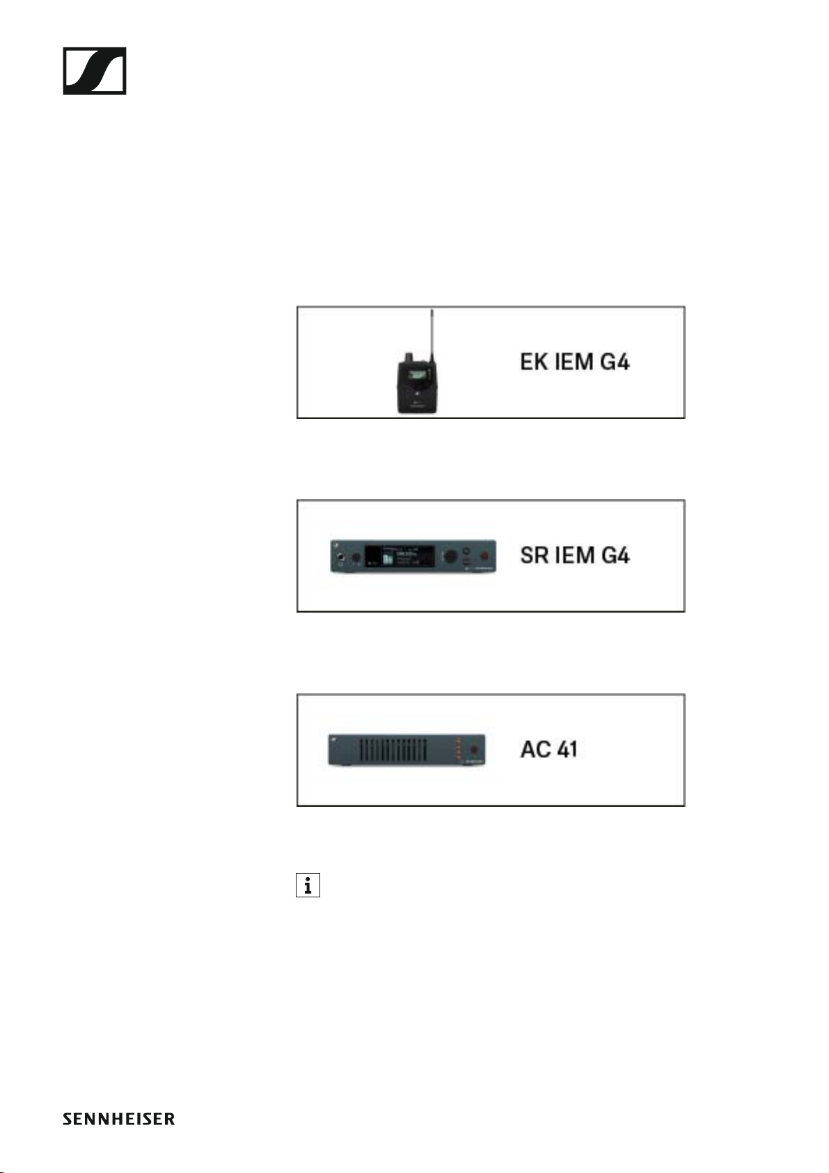
ew IEM G4 series products
ew IEM G4 series products
Click the name of the particular product to learn more about it.
You can also find more information here:
• A variety of frequency variants are available from the individual products. You can find more information under “Product variants”.
• You can find technical specifications about the individual products under “Specifications”.
• You can find information about installing the products under “Installing
and starting up ew IEM G4 series devices”.
• You can find information about operating the products under “Using
ew IEM G4 series devices”.
6
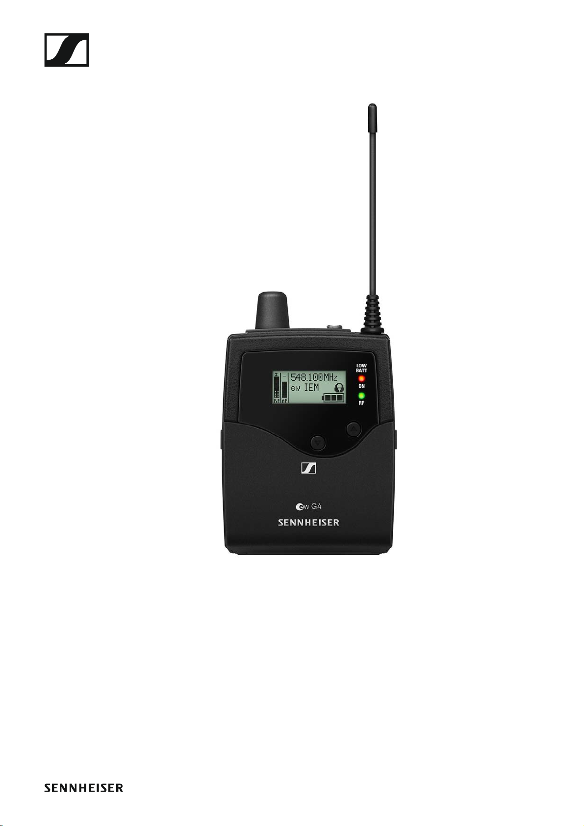
EK IEM G4 stereo diversity receiver
You can find more detailed information about the EK IE MG4 in the following sections:
• Installation and Startup: “Installing the EK IEM G4”
• Operation: “Using the EK IEM G4”
• Technical Data: “EK IEM G4”
7
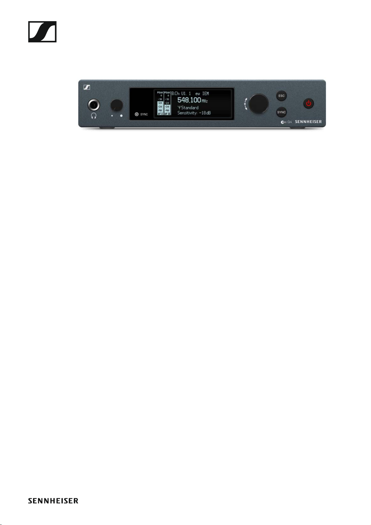
SR IEM G4 stereo transmitter
You can find more detailed information about the SR IEM G4 in the following sections:
• Installation and Startup: “Installing the SR IEM G4”
• Operation: “Using the SR IEM G4”
• Technical Data: “SR IEM G4”
8

Accessories
A variety of accessories are available for the ew IEM G4 series.
Earphones
IE 4
Article no. 500432
►
Accessories
You can find more information about the earphones on their product
page at www.sennheiser.com.
9
Accessories
Rechargeable battery and charger
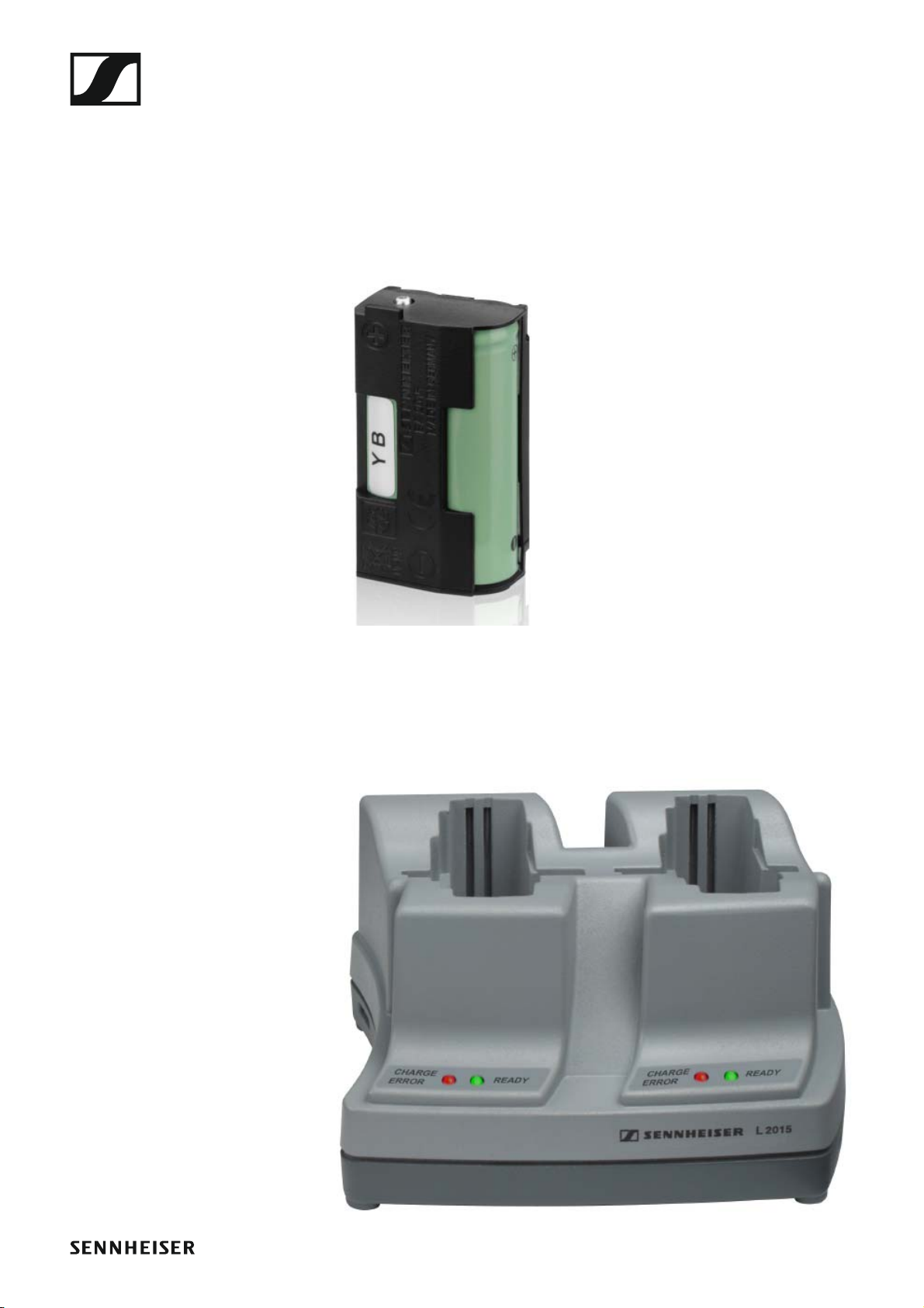
BA 2015 rechargeable battery
The BA 2015 rechargeable battery is designed for use with evolution wireless G4 series handheld transmitters, bodypack transmitters and
bodypack receivers.
Article no. 009950
►
L2015 charger
The BA 2015 rechargeable battery can be charged in the L 2015 charger on
its own or inside of the bodypack transmitter/bodypack receiver.
Article no. 009828
►
10
Accessories
Accessories for rack mounting
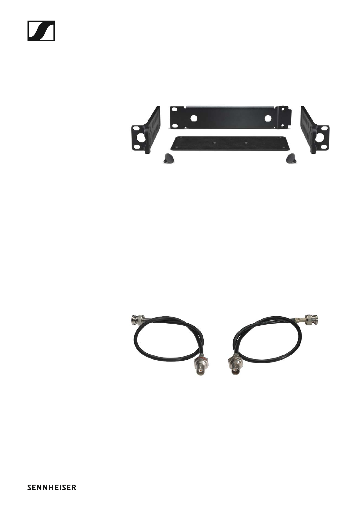
GA 3 rack mount kit
19” rack adapter for mounting the EM 100 G4, EM 300 G4, EM 500 G4 or
SR IEM G4 in a 19” rack.
Article no. 503167
►
AM 2 antenna front mounting kit
Antenna front mounting kit for installing antenna connections on the front
of the rack when using the EM 100 G4, EM 300 G4, EM 500 G4 or
SR IEM G4 together with the GA 3 rack mounting kit.
Article no. 009912
►
►
11
Accessories
Antennas and accessories
The following antenna components are available as accessory parts.
Omni-directional antennas
• A 1031-U, passive omni-directional antenna, article no. 004645
Directional antennas
• A 2003 UHF, passive directional antenna, article no. 003658
Antenna combiner
►
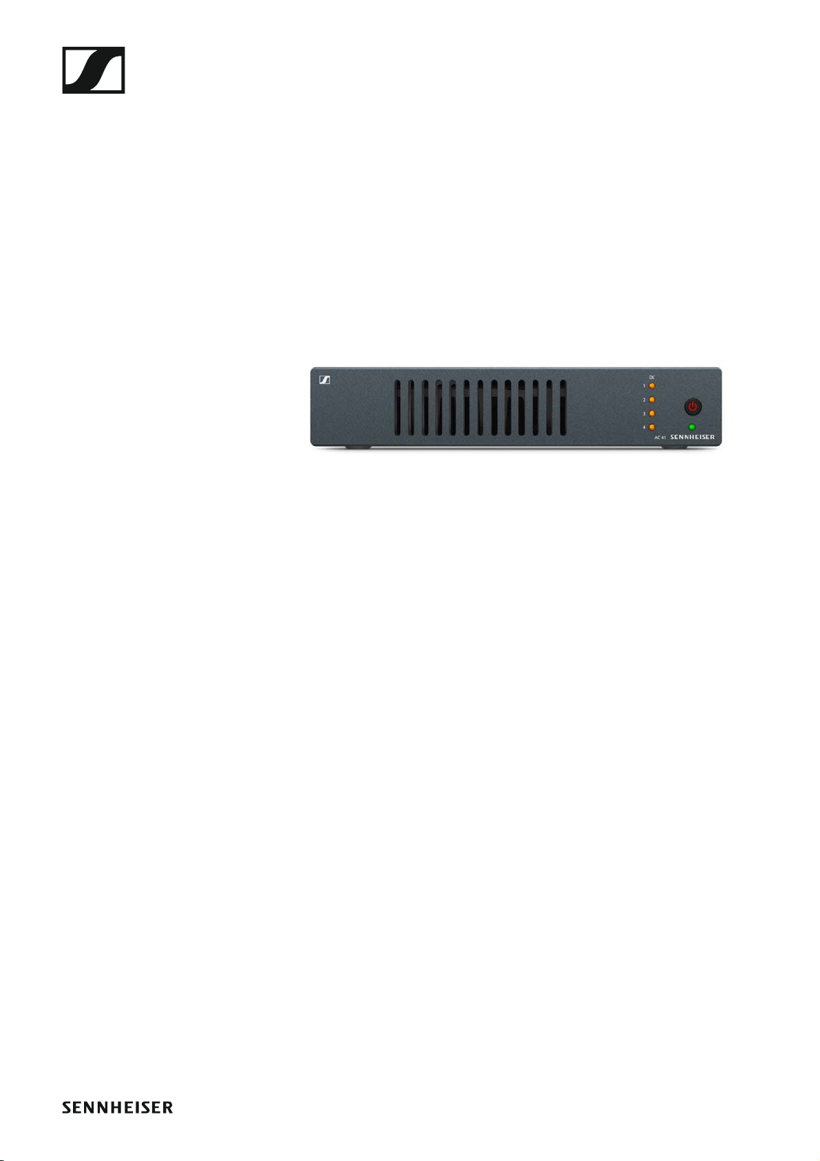
• AC 41, active antenna combiner
• ASA 41-EU, 470 – 870 MHz, article no. 508243
• AC 41-UK, 470 – 870 MHz, article no. 508295
• AC 41-US, 470 – 608 MHz, article no. 508244
Antenna cables
• GZL 1019, BNC/BNC coaxial cable, antenna cable with 50 ? characteristic (wave) impedance
• GZL 1019-A1 variant, 1 m (3 ft), article no. 002324
• GZL 1019-A5 variant, 5 m (16 ft), article no. 002325
• GZL 1019-A10 variant, 10 m (16 ft), article no. 002326
12
The frequency bank system
The frequency bank system
There are different frequency ranges in the UHF band available for transmission.
The following frequency ranges are available for the ew IEM G4 series:
• A1 range: 470 – 516 MHz
• A range: 516 – 558 MHz
• AS range: 520 – 558 MHz
• G range: 566 – 608 MHz
• GB range: 606 – 648 MHz
• B range: 626 – 668 MHz
• C range: 734 – 776 MHz
• D range: 780 – 822 MHz
• E range: 823 – 865 MHz
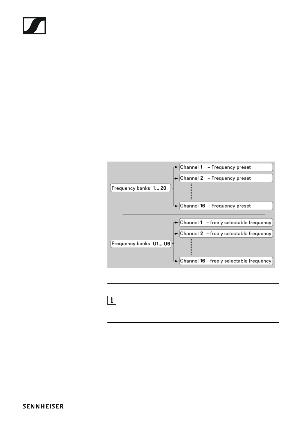
Every frequency range has 26 frequency banks with up to 16 channels:
►
You can find information about the frequency presets in the frequency tables of the respective frequency ranges under “Frequency tables”.
13
Installing and starting up ew IEM G4 series devices
INSTALLATION
Installing and starting up ew IEM G4 series devices
You can find information about installing and connecting ew IEM G4 series
devices in the following sections.
• EK IEM G4 diversity receiver >> “Installing the EK IEM G4”
• SR IEM G4 stereo transmitter >> “Installing the SR IEM G4”
• ASA 214 antenna combiner >> “Installing the AC 41”
You can find information about operating the products under “Using
ew IEM G4 series devices”.
14
Installing the EK IEM G4
Installing the EK IEM G4
These sections contain detailed information about installing and starting
up the EK IEM G4.
You can find information about operating the EK IEM G4 under “Using the
EK IEM G4”.
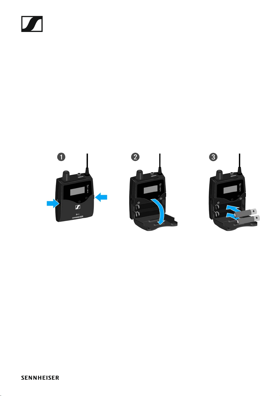
Inserting and removing the batteries/rechargeable batteries
You can operate the diversity receiver either with batteries (AA, 1.5 V) or
with the rechargeable Sennheiser BA 2015 battery.
▷ Press the two catches and open the battery compartment cover.
▷ Insert the batteries or the rechargeable battery as shown below. Please
observe correct polarity when inserting the batteries.
▷ Close the battery compartment.
The cover locks into place with an audible click.
15
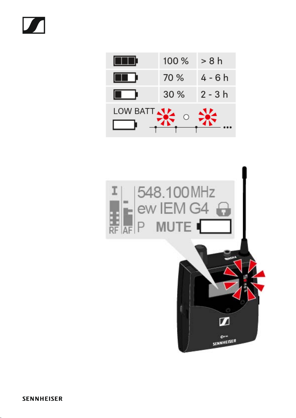
Battery status
Charge status of the batteries:
►
Installing the EK IEM G4
Charge status is critical (LOW BATT):
►
16

Installing the EK IEM G4
Connecting earphones to the EK IEM G4
ATTENTION
Danger due to high volume levels
Volume levels that are too high may damage your hearing.
▷ Turn down the volume of the headphone output before you put on the
headphone.
To connect the earphones to the receiver:
▷ Insert the cable’s 3.5 mm jack plug into the PHONES socket on the re-
ceiver as shown in the diagram.
►
The ground connection of the earphone cable acts as an antenna for
the second diversity branch. For details on the pin assignment, see
“Pin assignment”.
17
Installing the EK IEM G4
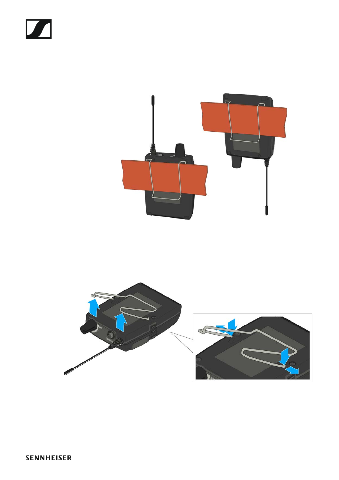
Attaching the diversity receiver to your clothing
You can use the belt clip to attach the diversity receiver to your waistband
or on a guitar strap.
The belt clip is detachable so that you can also attach the diversity receiver
with the antenna pointing downwards. To do so, withdraw the belt clip
from its fixing points and attach it the other way round.
►
The belt clip is secured so that it cannot slide out of its fixing points accidentally.
To detach the belt clip:
▷ Lift the belt clip as shown in the diagram.
►
▷ Press one side of the clip downward on the fixing hole and pull it out of
the housing.
▷ Do the same thing on the other side.
18
Installing the SR IEM G4
Installing the SR IEM G4
These sections contain detailed information about installing and starting
up the SR IEM G4.
You can find information about operating the SR IEM G4 under “Using the
SR IEM G4”.
Connectors on the rear of the device
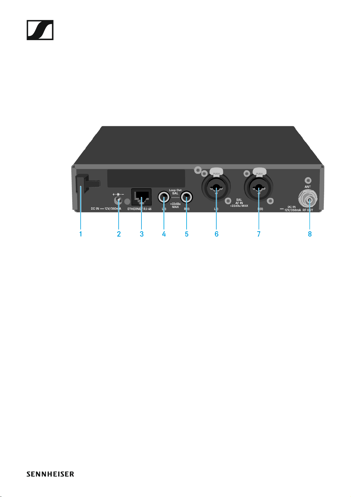
SR IEM G4 rear side product overview
►
1 Strain relief for the cable of the power supply unit
• See “Connecting/disconnecting the SR IEM G4 with/from the power
supply”
2 DC INsocket
• For connecting the power supply unit
• See “Connecting/disconnecting the SR IEM G4 with/from the power
supply”
3 LAN connection socket (ETHERNET RJ 45)
• See “Creating a data network”
4 6.3 mm jack socket LOOP OUT BAL L(I)
•Audio output, left
• See “Daisy chaining audio signals”
5 6.3 mm jack socket LOOP OUT BAL R(II)
•Audio output, right
• See “Daisy chaining audio signals”
6 XLR-3/6.3 mm jack combo socket BAL AF IN L(I)
• Audio input, left
• See “Connecting audio signals”
7 XLR-3/6.3 mm jack combo socket BAL AF IN R(II)
• Audio input, right
• See “Connecting audio signals”
8 RF OUT BNC socket
• Antenna output with remote power supply input
• See “Connecting antennas”
19
Installing the SR IEM G4
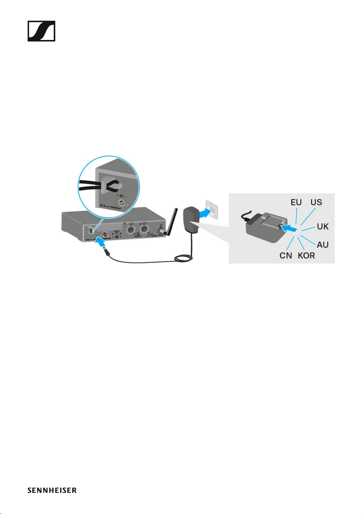
Connecting/disconnecting the SR IEM G4 with/ from the power supply
Only use the supplied power supply unit. It is designed for your receiver
and ensures safe operation.
To connect the SR IEM G4 transmitter to the power supply:
▷ Insert the plug of the power supply unit into the DC IN socket of the re-
ceiver.
▷ Pass the cable of the power supply unit through the cable grip.
▷ Slide the supplied country adapter onto the power supply unit.
▷ Plug the power supply unit into the wall socket.
To disconnect the SR IEM G4 transmitter from the power supply:
▷ Unplug the power supply unit from the wall socket.
▷ Unplug the power supply unit from the DC IN socket of the receiver.
20
Installing the SR IEM G4
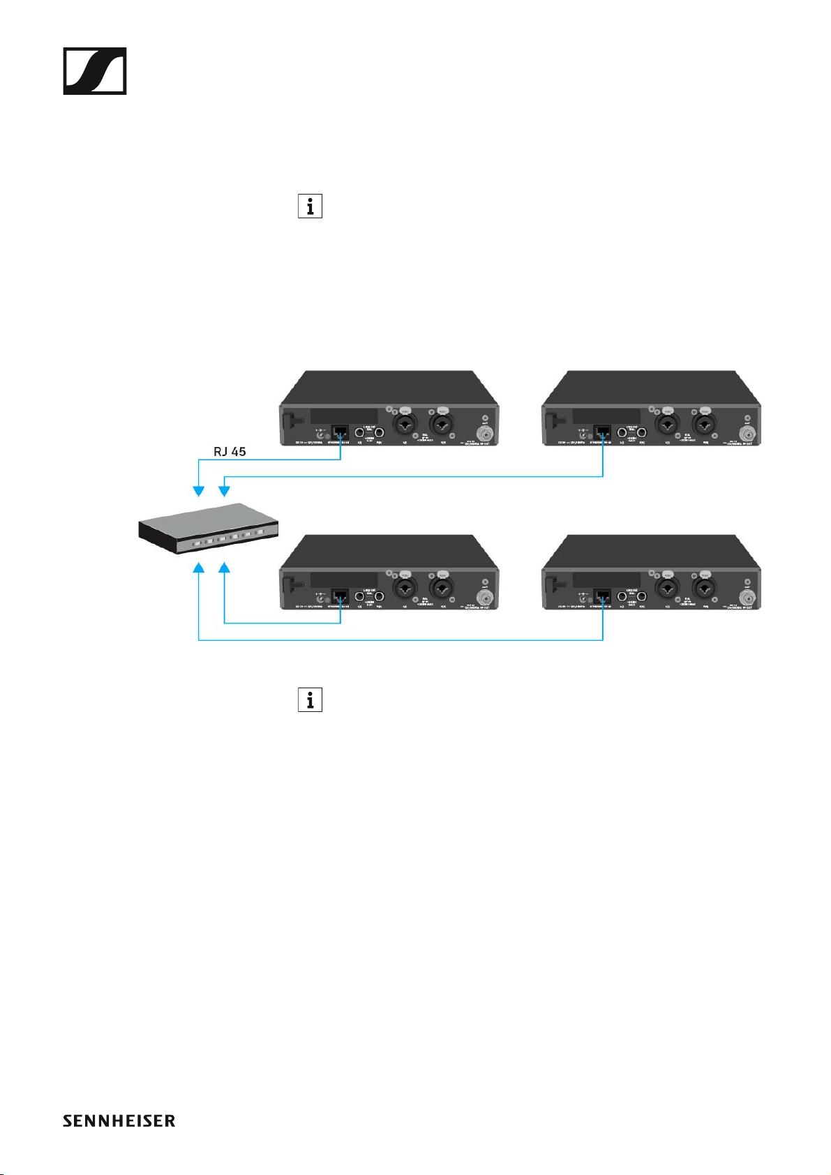
Creating a data network
You can monitor and control one or more SR IEM G4s via a network connection using Sennheiser Wireless Systems Manager (WSM) software.
Automatic frequency setup can also be performed over the network
without the WSM software. See “Easy Setup menu item”.
To connect the SR IEM G4 to a network:
▷ Connect a network cable with an RJ-45 connector (to the Ethernet
socket on the rear side of the SR IEM G4.
▷ Connect the other end of the network cable to a network switch.
►
For more information about controlling devices via the Sennheiser
Wireless Systems Manager (WSM) software, refer to the instruction manual for the software. You can download the software here:
www.sennheiser.com/wsm
21
Installing the SR IEM G4
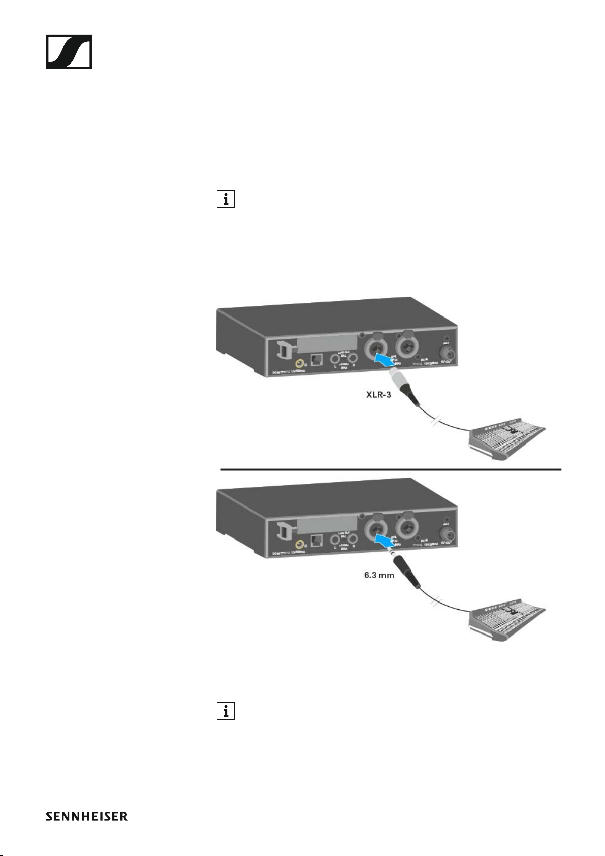
Connecting audio signals
You can connect Mono or Stereo signals via the two input sockets BAL AF
IN L(I) and BAL AF IN R(II).
To do so, the SR IEM G4 must be configured for Mono or Stereo operation
in the menu. See “Mode menu item”.
In Stereo mode, you can receive the two input signals either as a
mixed mono signal or as a stereo signal. To do so, you must select
Focus or Stereo mode on the EK IEM G4 receiver. See “Mode menu
item”.
Mono
▷ Connect the output of an external device (e.g. a mixing console or an-
other SR IEM G4) to the audio input socket BAL AF IN L(I) + MONO using a suitable cable.
In Mono mode, the corresponding EK IEM G4 receiver must be operated in Focus mode. See “Mode menu item”.
22
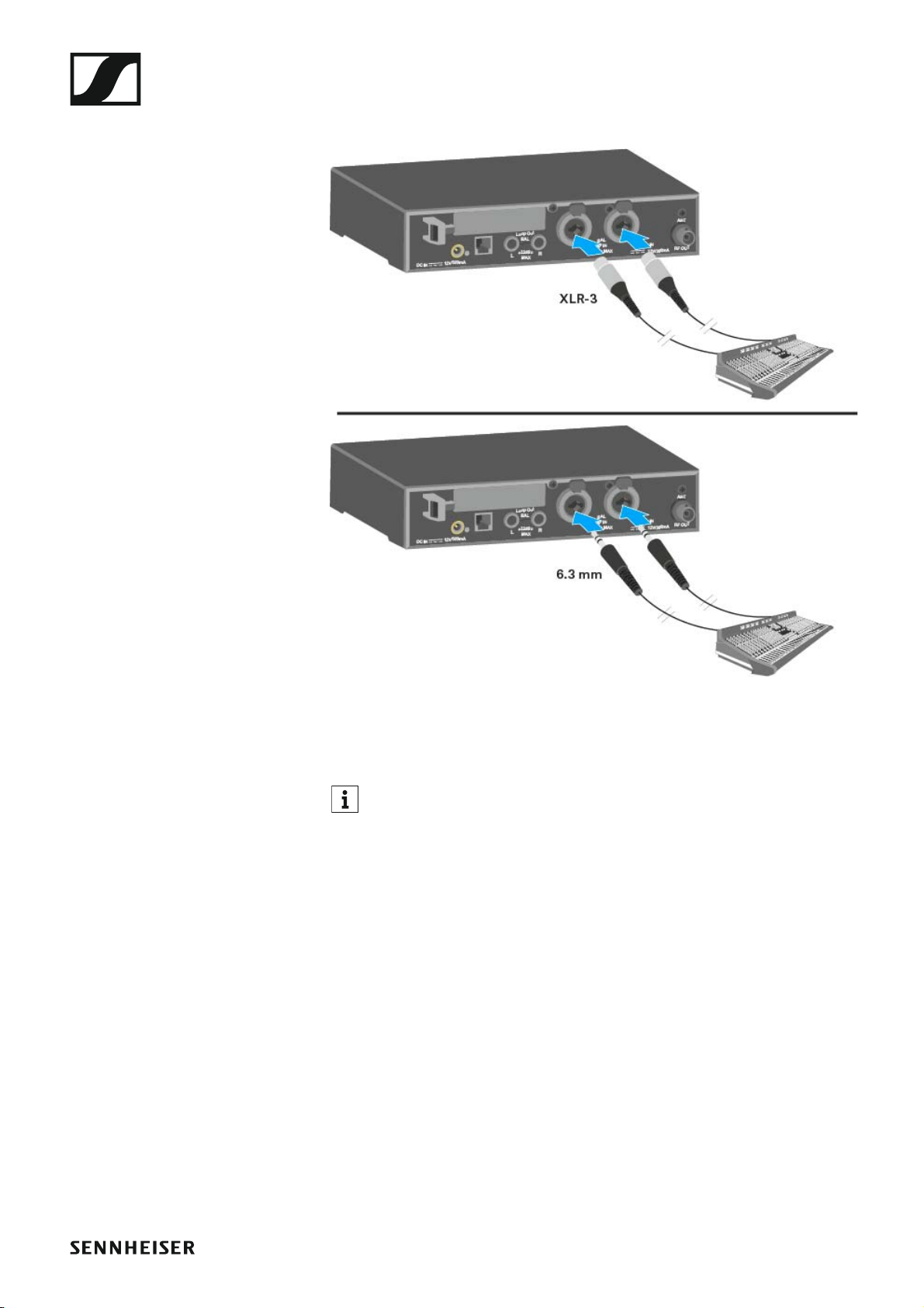
Stereo
Installing the SR IEM G4
▷ Connect the output of an external device (e.g. a mixing console or an-
other SR IEM G4) to the audio input sockets BAL AF IN L(I) and BAL AF
IN R(II) using suitable cables.
In Stereo mode, the corresponding EK IEM G4 receiver can be operated in Focus mode or Stereo mode. See “Mode menu item”.
23
Installing the SR IEM G4
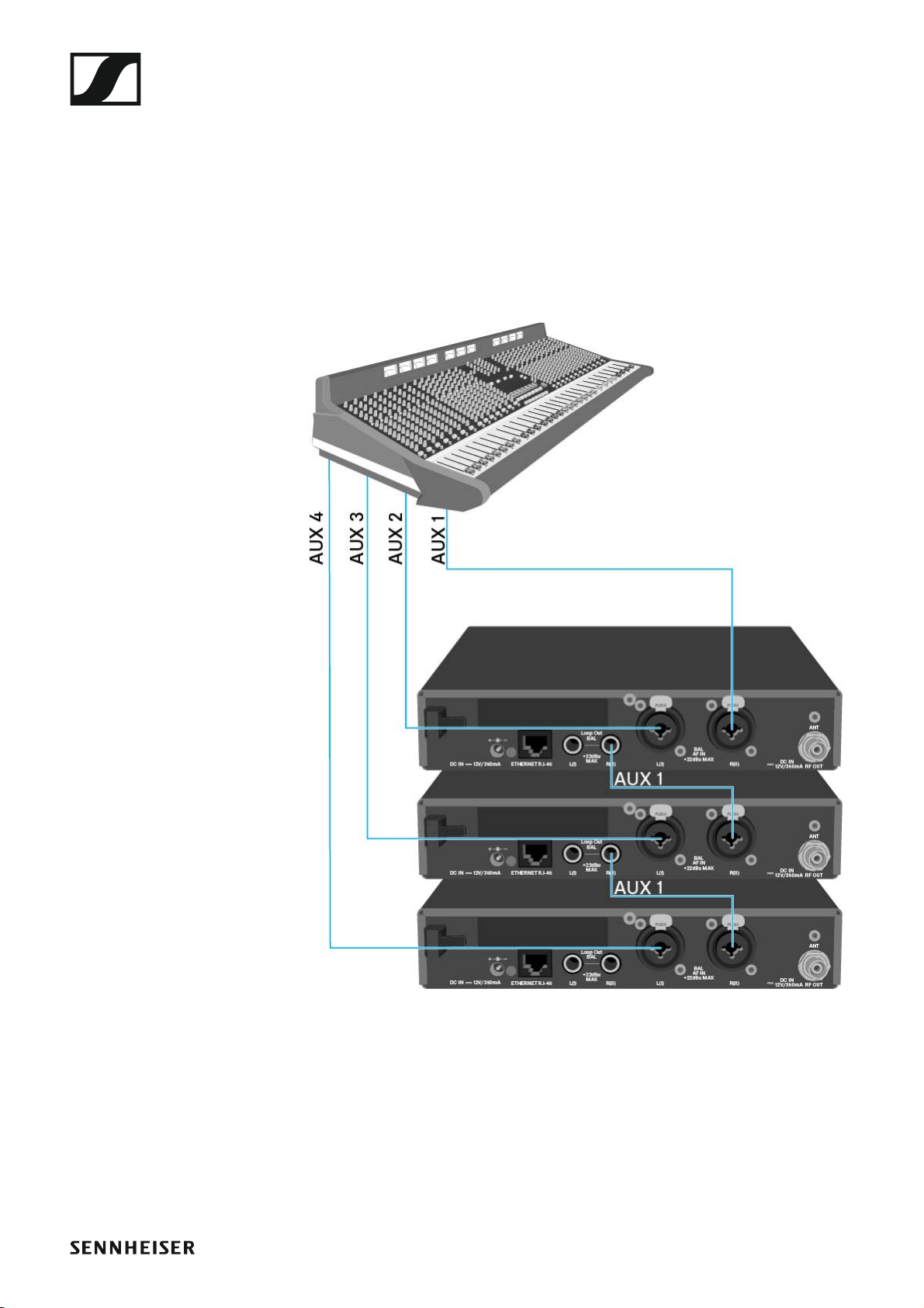
Daisy chaining audio signals
Using the LOOP OUT BAL L and/or LOOP OUT BAL R output sockets, it is
possible to transmit a signal that you want to make available to all receivers from the mixing console to a transmitter and then to daisy chain this
signal from the transmitter to the other transmitters.
In this way, for example, you can distribute an AUX path from the mixing
console in Focus mode to multiple transmitters and output a separate signal on the other channel of the same transmitter (e.g. for the individual musician).
▷ Transmit a signal from the mixing console to the input socket of trans-
mitter A (in this example: BAL AF IN R).
▷ Connect the LOOP OUT BAL R output socket of transmitter A with the
BAL AF IN R input socket of transmitter B.
▷ Now connect the LOOP OUT BAL R output socket of transmitter B with
the BAL AF IN R input socket of transmitter C.
▷ Continue on in this way for the remaining transmitters.
24
Installing the SR IEM G4
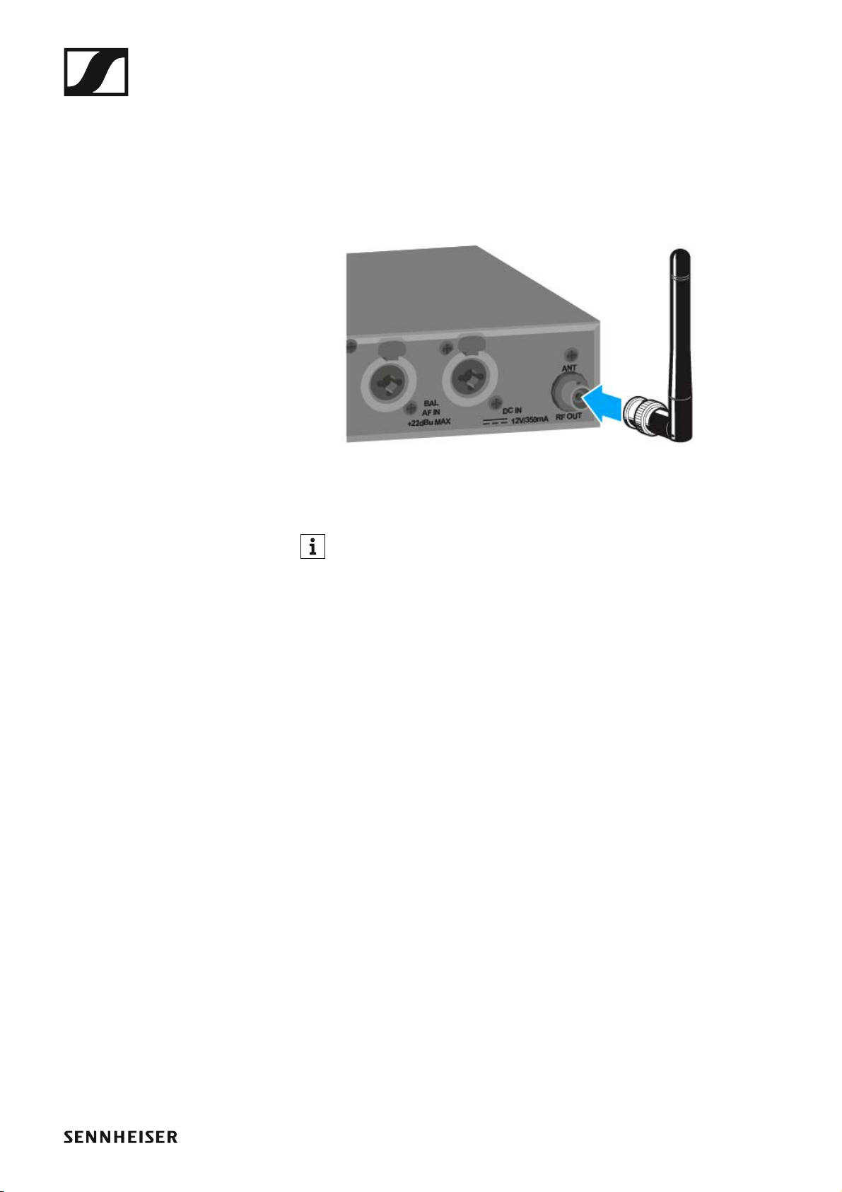
Connecting antennas
To connect the supplied rod antenna:
▷ Connect the rod antenna to the RF OUT socket on the rear side of the
SR IEM G4.
If you are using more than one transmitter, we recommend using remote antennas and the AC 41 antenna combiner. You can find more
information here:
• “Installing the AC 41”
• “Using the AC 41”
25

Installing the SR IEM G4
Installing the SR IEM G4 in a rack
CAUTION
Rack mounting poses risks
When installing the device in a closed or multi-rack assembly, please consider that, during operation, the ambient temperature, the mechanical
loading and the electrical potentials will be different from those of devices
which are not mounted into a rack.
▷ Make sure that the ambient temperature within the rack does not ex-
ceed the permissible temperature limit specified in the specifications.
See “Specifications”.
▷ Ensure sufficient ventilation; if necessary, provide additional ventila-
tion.
▷ Make sure that the mechanical loading of the rack is even.
▷ When connecting to the power supply system, observe the information
indicated on the type plate. Avoid circuit overloading. If necessary, provide overcurrent protection.
▷ When rack mounting, please note that intrinsically harmless leakage
currents of the individual power supply units may accumulate, thereby
exceeding the allowable limit value. As a remedy, ground the rack via
an additional ground connection.
26
Installing the SR IEM G4
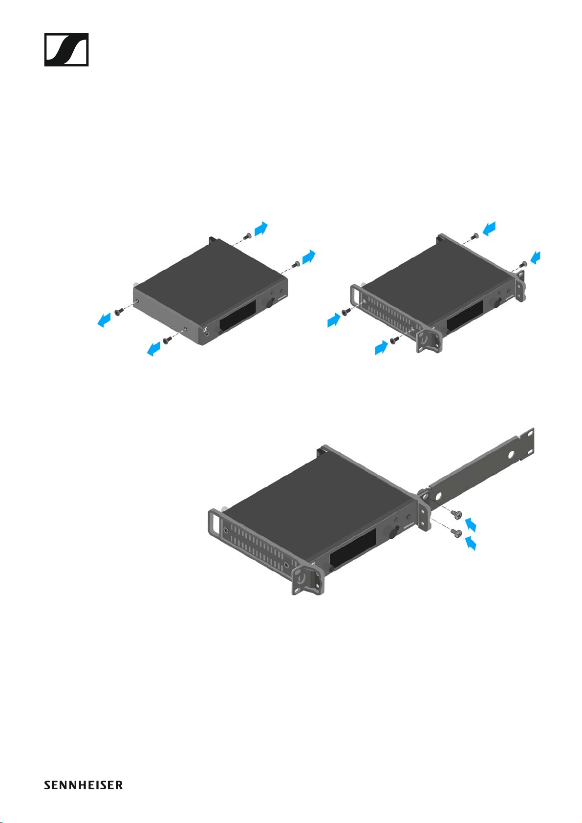
Mounting a single transmitter in a rack
To mount the transmitter in a rack, you will need the GA 3 rack mounting
kit (optional accessory).
To fasten the mounting angle of the GA 3 rack mounting kit:
▷ Unscrew and remove the two recessed head screws (M4x8) on each
side of the transmitter.
▷ Secure the left and right mounting angles to the sides of the transmitter
using the previously removed recessed head screws.
►
▷ Secure the blanking plate to one of the mounting angles using two re-
cessed head screws (M6x10).
27
Installing the SR IEM G4
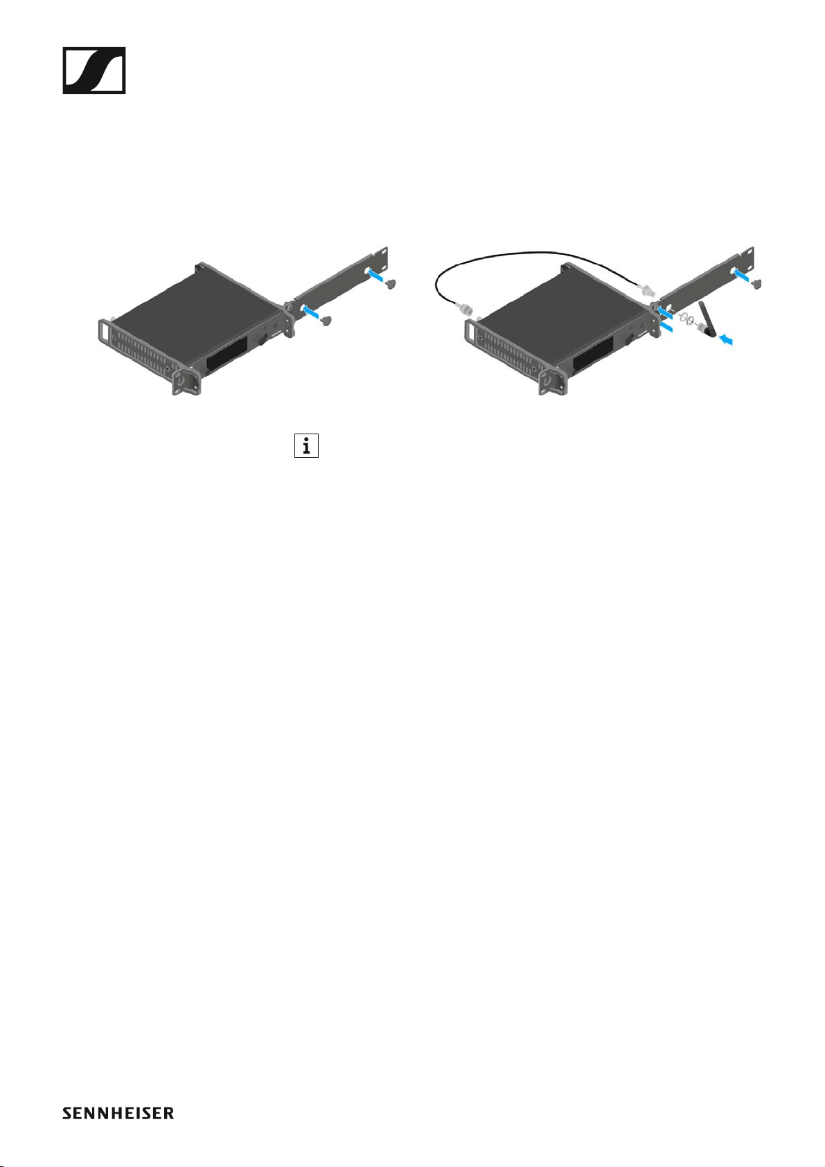
▷ Attach the antenna. You have the following options:
• Connect the supplied rod antenna on the rear side of the transmitter.
In this case, cover the antenna holes with the two covers (left diagram).
• Attach the AM 2 antenna front mounting set (optional accessory) and
mount the rod antenna on the blanking plate (right diagram).
• Use a remote antenna, possibly in combination with the AC 41 antenna combiner.
►
If you are using more than one transmitter, we recommend using remote antennas and, as needed, Sennheiser antenna accessories. For
more information, visit the ew G4 product page at www.sennheis-
er.com.
▷ Slide the transmitter with the mounted blanking plate into the 19" rack.
▷ Secure the mounting angle and the blanking plate to the 19" rack.
▷ Align the mounted antennas in a V-shape.
28
Installing the SR IEM G4
Mounting two receivers side by side in a rack
If you want to mount two transmitters side by side, you can mount the
antennas to the front of the rack in combination with the AC 41 antenna combiner. Otherwise, you can use the ASA 1 antenna splitter in
combination with the AM 2 front mounting kit and an additional GA 3 rack
mounting kit. For more information, visit the ew G4 product pages at
www.sennheiser.com.
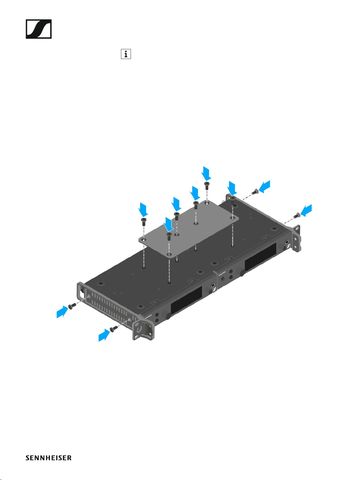
To mount the transmitter using the GA 3 rack mounting kit (optional accessory):
▷ Place both transmitters upside down and side by side on an even sur-
face.
▷ Secure the jointing plate to the transmitters using the six recessed
head screws (M3x6).
▷ Secure the mounting angle.
►
▷ Slide the connected transmitters into a 19" rack.
▷ Secure the mounting angle to the 19" rack.
29
 Loading...