

Sennheiser EK 500, SKM 500 User Manual
SKM 500
Instructions for use
EK 500
/

Thank you for choosing Sennheiser!
We have designed this product to give you reliable
operation over many years. Over half a century of
accumulated expertise in the design and manufacture of
high-quality electro-acoustic equipment have made
Sennheiser a world-leading company in this field.
Please take a few moments to read these instructions
carefully, as we want you to enjoy your new Sennheiser
product quickly and to the fullest.
34

Contents
The SKM 500 G2 radiomicrophone family ......................... 36
The channel bank system ............................................... 36
Safety instructions ................................................................. 37
Delivery includes .................................................................... 37
Areas of application ............................................................... 38
The operating controls .......................................................... 39
Indications and displays ....................................................... 40
Preparing the radiomicrophone for use ............................. 42
Inserting/replacing the batteries .................................. 42
Changing the microphone head .................................... 43
Using the radiomicrophone .................................................. 45
Switching the radiomicrophone on/off ....................... 45
Muting the radiomicrophone ......................................... 46
Activating/deactivating the lock mode ....................... 46
The operating menu .............................................................. 47
The buttons ....................................................................... 47
Overview of menus .......................................................... 47
Working with the operating menu ............................... 48
Operating menu of the radiomicrophone .................... 50
Adjustment tips for the operating menu .......................... 52
Switching between channel banks ............................... 52
Switching between the channels in a channel bank . 52
Selecting the frequencies to be stored
in the channel bank “U” .................................................. 52
Adjusting the sensitivity ................................................ 53
Selecting the standard display ...................................... 54
Entering a name ............................................................... 54
Loading the factory-preset default settings .............. 54
Activating/deactivating the pilot tone transmission 55
Activating/deactivating the lock mode ....................... 55
Exiting the operating menu ........................................... 55
Troubleshooting ..................................................................... 56
Error checklist ................................................................ 56
Recommendations and tips ........................................... 57
Care and maintenance ........................................................... 58
Specifications .......................................................................... 59
Polar diagrams and frequency response curves
of microphone heads ....................................................... 60
Accessories .............................................................................. 61
35
The SKM 500 G2
radiomicrophone family
The SKM 500 G2 radiomicrophone family is part of the evo-
lution wireless series ew 500 G2. With this series, Sennheiser offers high-quality state-of-the-art RF transmission systems with a high level of operational reliability and
ease of use. Transmitters and receivers permit wireless
transmission with studio-quality sound. The excellent
transmission reliability of the ew 500 G2 series is based on
the use of
y further optimized PLL synthesizer and microprocessor
technology,
y the HDX noise reduction system,
y and the pilot tone squelch control.
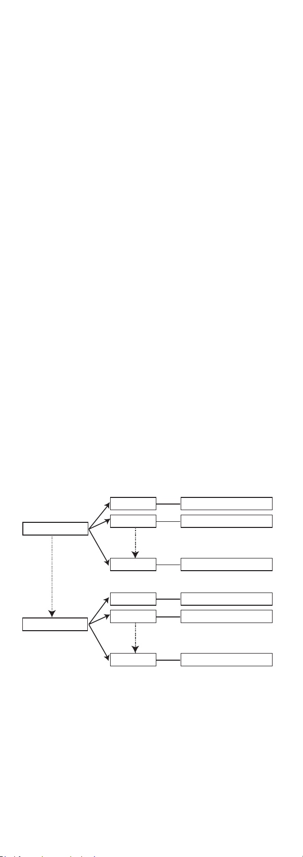
The channel bank system
The radiomicrophone is available in five UHF frequency
ranges with 1440 transmission frequencies per frequency
range. Please note: Frequency usage is different for each
country. Your Sennheiser agent will have all the necessary
details on the available legal frequencies for your area.
Range A: 518 to 554 MHz
Range B: 626 to 662 MHz
Range C: 740 to 776 MHz
Range D: 786 to 822 MHz
Range E: 830 to 866 MHz
The radiomicrophone has nine channel banks with up to 20
switchable channels each.
channel bank 1... 8
channel bank U
channel 1
channel 2
channel 20
channel 1
channel 2
channel 20
preset frequency
preset frequency
preset frequency
freely selectable frequency
freely selectable frequency
freely selectable frequency
Each of the channels in the channel banks “1” to “8” has
been factory-preset to a transmission frequency (see
enclosed frequency table). These transmission frequencies
cannot be changed but have been preset so that e.g.
country-specific regulations on frequency usage are taken
into account.
The channel bank “U” (user bank) allows you to store your
36

selection out of 1440 transmission frequencies that are
freely selectable within the preset frequency range.
Safety instructions
Never open an electronic unit! If units are opened by
customers in breach of this instruction, the warranty
becomes null and void.
Use the unit in dry rooms only.
Use a damp cloth for cleaning the unit. Do not use any
cleansing agents or solvents.
Delivery includes
The packaging contains the following items:
y 1 SKM 500 G2 radiomicrophone
y 2 batteries
y 1 microphone clamp
y Instructions for use
y 1 pouch
37

Areas of application
The SKM 500 G2 radiomicrophone family can be combined
with receivers of the ew 500 G2 series (EM 500 G2 rackmount receiver or EK 500 G2 bodypack receiver). The
receivers are available in the same five UHF frequency
ranges and are equipped with the same channel bank
system with factory-preset frequencies. An advantage of
the factory-preset frequencies is that
y a transmission system is ready for immediate use after
switch-on,
y several transmission systems can be operated simultane-
ously on the preset frequencies without causing intermodulation interference.
Together with a matching receiver, the radiomicrophone is
suitable for the following areas of application:
Transmitter Receiver (to be
ordered separately)
EM 500 G2
Area of
application
y
Presentation
y Vocals
SKM 535 G2
SKM 545 G2
SKM 565 G2
1)
1)
1)
EK 500 G2
y
Speech
y Vocals
y Presentation
y Camera-mounted
applications
The name
1)
of the radiomicrophone is a combination of the
name of the transmitter and the name of the microphone
head:
Transmitter+Microphone head = Name of radiomicrophone
SKM 500 +MD 835 = SKM 535
Each microphone head comes with a color-coded
identification ring to distinguish different microphone
heads from each other.
Microphone
head
Color of i
dentification ring
Transducer
principle
MD 835 green dynamic cardioid Speech, vocals
MD 845 blue dynamic super-
ME 865 red condenser super-
2)
MMD 935
(optional)
2)
only avilable as optional microphone head
silver dynamic cardioid Vocals (in venues
Picxk-up
cardioid
cardioid
pattern
Vocals (high
feedback rejection)
Vocals (
feedback rejection)
with high ambient
noise levels)
Area of
high
38
application
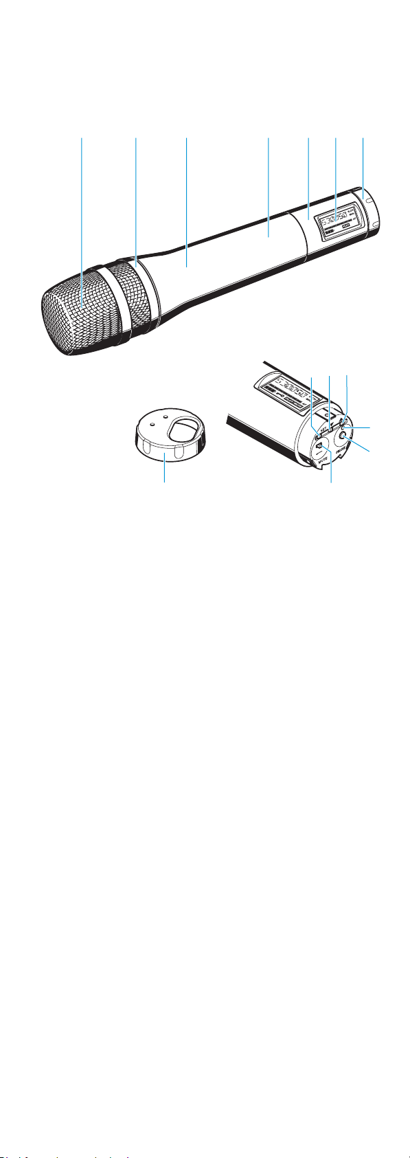
The operating controls
Sound inlet basket
Color-coded identification ring for microphone heads
green: MD 835 microphone head
blue: MD 845 microphone head
red: ME 865 microphone head
Body of radiomicrophone
Battery compartment (not visible from outside)
Display section
LC display
Turnable protective cap for operating controls (shown
removed)
The following operating controls become accessible in
turn by turning the protective cap:
SET button
button (DOWN)
button (UP)
Red LED for operation and
battery status indication (ON/LOW BAT)
ON/OFF button
(serves as the ESC (cancel) key in the
operating menu)
MUTE switch
39
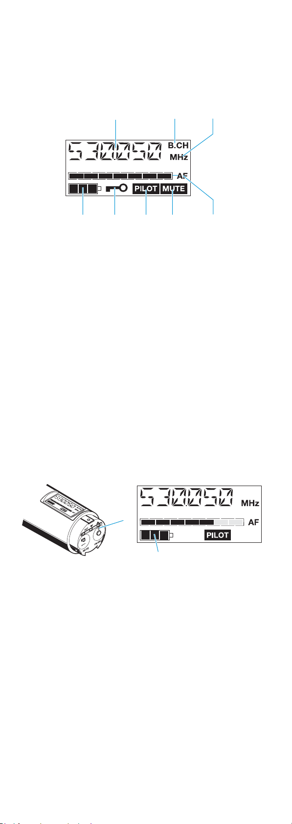
Indications and displays
LC display panel
Alphanumeric display
“B.CH“ – appears when the channel bank and
the channel number are displayed
“MHz“ – appears when the frequency is displayed
4-step battery status display
Lock mode icon
(lock mode is activated)
“PILOT” display
(pilot tone transmission is activated)
“MUTE” display
(audio input is muted)
7-step level display for audio signal “AF”
Operation and battery status indication
The red LED (LOW BAT/ON) provides information on the
current operating state of the radiomicrophone:
Red LED lit up: The radiomicrophone is switched
on and the capacity of the
batteries/BA 2015 accupack is
sufficient.
Red LED flashing: The batteries are/the BA 2015
accupack is going flat (LOW BAT)!
In addition, the 4-step battery status display on the
display panel provides information on the remaining
battery/BA 2015 accupack capacity:
3 segments: capacity approx. 100 %
2 segments: capacity approx. 70 %
1 segment: capacity approx. 30 %
Battery icon flashing: LOW BAT
40

“MUTE” display
The “MUTE” display appears on the display panel when
the radiomicrophone is muted (see “Muting the
radiomicrophone” on page 46).
Modulation display
The level display for audio signal “AF” shows the
modulation of the radiomicrophone.
When the audio input level is excessively high, the level
display for audio signal “AF” shows full deflection for the
duration of the overmodulation.
“PILOT” display
The “PILOT” display appears on the display panel when
the pilot tone transmission is activated (see “Activating/
deactivating the pilot tone transmission” on page 55).
Display backlighting
After pressing a button, the display remains backlit for
approx. 15 seconds.
41
Preparing the radiomicrophone
for use
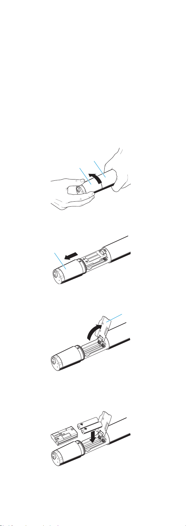
Inserting/replacing the batteries
For powering the radiomicrophone, you can either use two
1.5 V AA size batteries or the rechargeable Sennheiser
BA 2015 accupack.
Unscrew the display section from the
radiomicrophone’s body by turning it counterclockwise.
Slide back the display section as far as it will go.
Open the battery compartment cover .
Insert the two batteries or the BA 2015 accupack as
shown. Please observe correct polarity when inserting
the batteries/accupack.
Close the battery compartment cover .
42
Push the battery compartment into the
radiomicrophone’s body.
Screw the display section tight.
Note:
For accupack operation of the radiomicrophone, only use
the BA 2015 accupack in order to ensure optimum
operational reliability. For charging the accupack, only
use the L 2015 charger. Both the accupack and the
charger are available as accessories.
The accupack is fitted with an integrated sensor which is
– via a third contact – monitored by the electronics of
the radiomicrophone and the charger. The sensor is
necessary for the following control purposes:
y The taking into account of the different voltage
characteristics of primary cells (batteries) and
accupacks. The battery status indications on the
displays, the transmission of transmitter battery
status information to the rack-mount receivers and
the switch-off thresholds at the end of the operating
time are corrected correspondingly. Due to the
missing sensor, individual rechargeable battery cells
will not be identified as accupacks.
y The monitoring of the accupack temperature during
charging in the L 2015 charger.
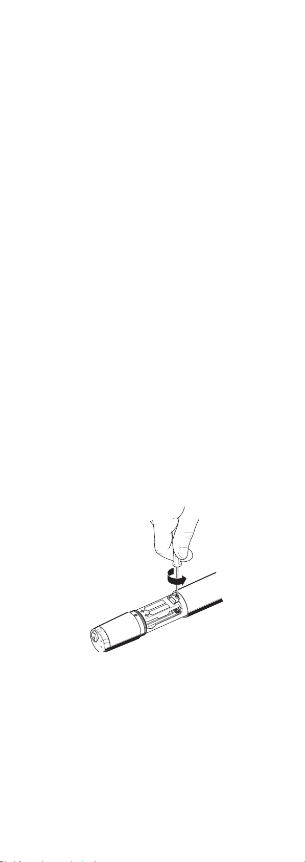
Changing the microphone head
First remove the batteries/accupack as described above
and leave the radiomicrophone open.
Unscrew the sound inlet basket.
Loosen the screw and put it to one side.
43
 Loading...