

Page 1

EK 500
EK 3241
Instructions for use
/
Page 2

Contents
Safety instructions .................................................................... 3
Delivery includes ....................................................................... 3
The EK 3241 true diversity receiver ...................................... 4
Operating controls .................................................................... 5
LC display panel ......................................................................... 5
Putting the receiver into operation ....................................... 6
Connecting the antennas ................................................... 6
Mounting the receiver into a camcorder ........................ 6
Powering the receiver ........................................................ 7
Using the receiver ..................................................................... 8
Switching the receiver on/off ........................................... 8
The operating menu ................................................................. 9
The functions of the buttons ............................................ 9
Working with the operating menu ............................... 10
Overview of the operating menu .................................. 14
Adjustment tips for the operating menu .......................... 16
Adjusting the headphone volume – PHonE ................ 16
Selecting a channel – CHAn ............................................ 16
Selecting the frequencies to be stored in the
channel bank “U” (variable bank) – tunE ................... 17
Adjusting the squelch threshold – SquELH ................. 17
Activating/deactivating the automatic receiver
switch-on/off via the camcorder – Auto ..................... 17
Selecting the standard display – dISP ......................... 18
Loading the factory-preset
default settings– rESEt ................................................... 18
Activating/deactivating the lock mode – Loc ............ 18
Exiting the selection mode and returning to
the standard display – ESc ............................................. 18
Care and maintenance ........................................................... 19
If a problem occurs ... ............................................................. 20
Error checklist ................................................................... 20
Recommendations and tips ................................................. 21
Additional information ......................................................... 22
Diversity reception ........................................................... 22
Information on the compander system ....................... 22
Accessories .............................................................................. 23
Operating the EK 3241 with headphones ................... 23
Specifications .......................................................................... 24
Connector assignment (operation with GA 3041-C) 25
Manufacturer Declarations ................................................... 26
Warranty regulations ...................................................... 26
CE Declaration of Conformity ......................................... 26
Batteries and rechargeable batteries ........................... 26
WEEE Declaration ............................................................. 26
1
Page 3

Thank you for choosing Sennheiser!
We have designed this product to give you reliable operation over
many years. Over 60 years of accumulated expertise in the design and
manufacture of high-quality electro-acoustic equipment have made
Sennheiser a world-leading company in this field.
Please take a few moments to read these instructions carefully, as we
want you to enjoy your new Sennheiser products quickly and to the
.
fullest
2
Page 4

Safety instructions
y Please read these instructions carefully and completely
before using the receiver.
y Make these instructions easily accessible to all users at all
times. Always include these instructions when passing
the receiver on to third parties.
y Never open electronic units! If units are opened by
customers in breach of this instruction, the warranty
becomes null and void.
y Water entering the housing of the receiver can cause a
short-circuit and damage the electronics. Protect the
receiver from damp and wet. Only use a slightly damp
cloth to clean the receiver.
Intended use of the receiver
“Intended use” means that the receiver should be used
within the operating conditions and limitations described in
these instructions.
Improper use
“Improper use” means using the receiver other than as
described in these instructions, or under operating
conditions which differ from those described herein.
Delivery includes
Delivery of the EK 3241 receiver includes:
y 1 EK 3241 true diversity receiver
y 2 antennas
y 1 instructions for use
For accessories, please refer to page 23.
3
Page 5

The EK 3241 true diversity receiver
The EK 3241 is a miniature true diversity receiver designed
for use with digital ENG camcorders. It can be inserted into
the slot-in facility of e.g. Ikegami, Panasonic, Sony or
Thomson camcorders without any additional connecting
cables being required. The GA 3041-C slot-in housing is
used for externally attaching the receiver to camcorders
without a slot-in facility. Together with a suitable
Sennheiser bodypack or hand-held transmitter, a highly
reliable radio link can be set up.
The EK 3241 receiver has the following features:
y Extremely compact and robust all-metal housing
y Special protection against the ingress of moisture and
therefore suitable for outdoor applications
y Mounting kits available for all current professional
camcorders
y Power supply via camcorder or GA 3041-B battery
adapter
y User-friendly, menu-assisted operation via LC display
y High operational reliability due to true diversity reception
y HiDyn plus™ noise reduction system
y Up to 32 preset receiving frequencies
y 36 MHz switching bandwidth
y Frequencies tunable in steps of 5 kHz
y Signal-to-noise ratio >110 dB
S/N
.
Suitable transmitters
Bodypack transmitters: SK 50, SK 250, SK 3063,
SK 5012, SK 5212
Hand-held transmitters: SKM 3072, SKM 5000, SKM 5200
Plug-on transmitters: SKP 3000
4
Page 6

Operating controls
SET button
Antenna socket, diversity section A
ON/OFF button
LC display panel
button (Down)
button (UP)
Antenna socket, diversity section B
쐋
LC display panel
“RF” – appears when an RF signal is being received
8-step level display for received RF signal
Numeric display
8-step level display for received audio signal
햴
5
Page 7
Putting the receiver into operation
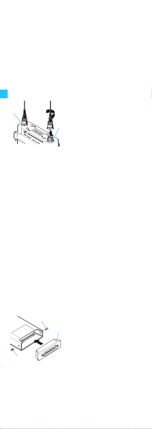
Connecting the antennas
The receiver is supplied with two antennas which are
necessary for true diversity operation (see “Diversity
reception” on page 22).
Connect the antennas to the
Mounting the receiver into a camcorder
antenna sockets and .
Screw the antennas tight.
The receiver can be inserted into the slot-in facility of most
professional camcorders. Suitable mounting kits are available as accessories from your Sennheiser partner.
Mounting kits are available for the following camcorder
types (see “Accessories” on page 23):
Camcorder Mounting kit
Sony GA 3041-15 (15-pin)
Ikegami, Panasonic GA 3041-25 (25-pin)
Thomson GA 3041-44 (44-pin)
A mounting kit consists of:
y 1 sub-D adapter
y 1 mounting frame
y Screws
By way of example of an Ikegami or Panasonic camcorder,
the following describes how to insert the receiver into the
camcorder’s integrated receiver slot:
Secure the sub-D adapter to
the bottom of the receiver
using two screws .
6
Page 8
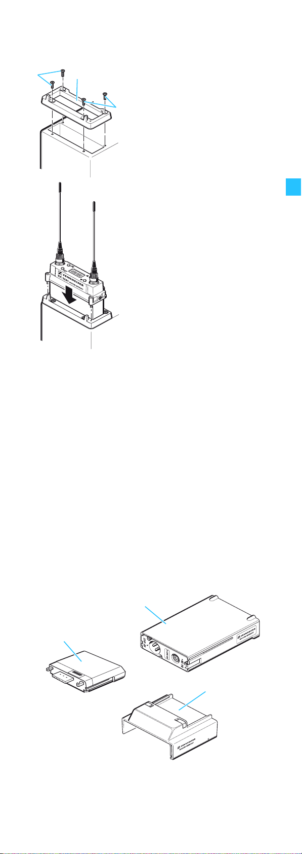
Secure the mounting frame
to the camcorder housing
using four screws .
Insert the receiver into the
slot-in facility until the 25-pin
connector securely connects.
Screw the receiver (from
above) to the mounting frame.
Powering the receiver
The receiver can be powered from three different power
sources:
Power source Notes on operation
Camcorder with mounting kit See page 6
Camcorder with
GA 3041-C slot-in housing
GA 3041-C slot-in housing
with GA 3041-B battery
adapter and BA 50/BA
250 accupack or B 50/B 250
battery box
See instructions for use
of the GA 3041-C
See “Accessories” on
page 23 and
instructions for use
of the GA 3041-C
7
Page 9

Using the receiver
Switching the receiver on/off
Note:
The receiver can only be switched off when the lock
mode is deactivated (see “Activating/deactivating the
lock mode – Loc” on page 18).
neue Abb.
von
Sennheiser
Note:
When in the setting mode of the operating menu, the
ON/OFF button will cancel your entry (ESC function).
To switch the receiver on,
briefly press the ON/
OFF button .
The standard display is shown
on the LC display panel
To switch the receiver off,
press the ON/OFF button
until “OFF” appears on the LC
display panel
The LC display panel goes off.
.
.
8
Page 10

The operating menu
The functions of the buttons
Button Mode Function
ON/OFF Switched off Switches the receiver on
Display mode y Briefly pressing the button
(with activated lock mode):
Calls up the lock mode for
deactivation
y Pressing the button for
3 sec. (with deactivated lock
mode):
Switches the receiver off
Selection mode Cancels the entry and returns
to the display mode
Setting mode Cancels the entry and returns
with the last setting stored to
the last parameter displayed
in the display mode
SET Display mode y With deactivated lock mode:
Changes to the selection
mode
y With activated lock mode:
Calls up the lock mode for
deactivation
Selection mode Changes to the setting mode
of the selected menu
Setting mode Stores the setting and returns
to the selection mode
(“StorEd” is displayed)
/ Display mode Changes to the previous
parameter () or changes to
the next parameter ()
Selection mode Changes to the previous menu
() or changes to the next
menu ()
Setting mode Increases () or reduces ()
the setting of the selected
menu
9
Page 11

Working with the operating menu
By way of example of the “dISP” menu, this section
describes how to use the receiver’s operating menu.
The operating menu has three modes:
y Display mode
In display mode, you can display the current menu
settings one after the other – even when the lock mode is
activated.
y Selection mode
In selection mode, you can select the menu whose setting
you want to change. To change to the selection mode, the
lock mode must be deactivated.
y Setting mode
In setting mode, you can change the setting of the
selected menu.
Display mode
Current
standard display
Selection mode
dISP
SET SET
Selecting the
standard display
FrEq
Current
setting
StorEd
Setting mode
CHAn
CHAn, FrEq, Bat.tr
SET
:
After switch-on
After switch-on, the standard display is shown on the
LC display panel. Depending on the setting, the receiving
frequency, the channel number or the battery status of the
corresponding transmitter is displayed.
Note:
In order that the transmitter battery status can be
displayed on the “BAt.tr” standard display, this
functionality must be supported by the transmitter
used (see “Suitable transmitters” on page 4).
10
Page 12

Displaying the menu settings in display mode
In display mode, and with the lock mode activated, you can
display the current menu settings one after the other (see
“Overview of the operating menu” on page 14).
button or the
ON
SET
Press the
button to display the
menu settings. If you press the
button repeatedly, all menu
settings are displayed one
after the other.
After approx. 15 seconds, the
display returns to the
standard display.
Changing to the selection mode
To change from display mode to selection mode, you have
to deactivate the lock mode.
ON
SET
Selecting a menu
ON
SET
Deactivate the lock mode as
described in the chapter
“Activating/deactivating the
lock mode – Loc” on page 18.
Press the
button to select the
button or the
menu whose settings you
want to adjust.
Press the SET button to
change to the menu that was
displayed in display mode.
Press the
button.
button or the
Press the SET button .
The name of the selected
menu starts flashing.
11
Page 13

The following menus are available:
Menu Function of the menu
PHonE Adjusting the headphone volume*
CHAn Selecting a channel
tunE Setting receiving frequencies for the
channel bank “U” (variable bank)
SquELH Adjusting the squelch threshold
Auto Activating/deactivating the automatic receiver
switch-on/off via the camcorder
dISP Selecting the standard display
rESEt Loading the factory-preset default settings
Loc Activating/deactivating the lock mode
ESc Exiting the selection mode and returning
to the standard display
*) If the receiver is inserted into the slot-in facility of a
camcorder, the “PHonE“ menu is deactivated
(see
page 23).
Changing to the setting mode of a selected menu
ON
SET
Press the SET button to
Adjusting a setting
Use the
button or the button to adjust the
setting of the selected menu.
y
By pressing the button or
the
ON
SET
jumps either forwards or
backwards to the next setting.
y
In the “CHAn”, “tunE”, “PHonE”
or “SquELH” menu, the
buttons
“fast search” function, i.e. the
display cycles continuously.
the “
the display is continuously
accelerated. The “fast search”
function allows you to get fast
and easily to your desired
setting.
change to change to the
setting mode of the selected
menu.
The current setting that can be
adjusted flashes on the LC
display panel .
button, the display
and
feature a
tunE
” menu, the cycling of
In
12
Page 14

Storing a setting
ON
SET
Cancelling an entry
Press the SET button
permanently store a setting
StorEd
“
” appears on the
display panel, indicating that
the setting has been stored.
The display then returns to
selection mode.
to
.
ON
SET
Select the “ESc” menu to exit
the selection mode and to
return to the standard display.
When in the selection or
setting mode, briefly pressing
the ON/OFF button will
cancel your entry (ESC
function) and return you to
the standard display with the
last stored settings.
13
Page 15

Overview of the operating menu
Deactivate the lock mode before adjusting the settings (see
“Activating/deactivating the lock mode – Loc” on page 18).
Pressing the ON/OFF button will cancel your entry (ESC
function) and return you to the display mode.
Display mode
Current
headphone volume
Current
channel bank
Current
frequency
Selection mode
PHonE
Adjusting the
headphone
volume
CHAn
Changing the
channel bank
and the channel
SET
tunE
Setting the frequencies
for the channels of
channel bank “U”
Setting mode
SETSET
PH . 95 PH . 15
Current setting
StorEd
/ :
PH . 0...PH . 126,
in steps of 1
SET
550.385
1 sec.
Receiving frequency
1 sec.
SETSET
U . 20
:
Channel
U .01...U .20
F .01...F .32
StorEd
RF
SET
550.385 516.205
Current
frequency
StorEd
SET
SET
F . 01
:
Channel
F .01...F .32
U .01...U .20
:
Adjusting the
frequency
Current
squelch threshold
Current setting
of switch-on
function
14
SquELH
Adjusting the
squelch threshold
Auto
Automatic
switch-on via
camcorder or
manual switch-on
SETSET
SqL. 35 SqL. 25
Current setting
StorEd
SETSET
Aut. on Aut. oFF
Current setting
StorEd
SET
SET
:
O5...40
in steps of 5
:
on, oFF
Page 16

Display mode
Selection mode
Setting mode
Current
standard display
dISP
Selecting the
standard display
rESEt
Loading the
factory-preset
default settings
Loc
Setting the
autolock function
ESc
Exiting the
operating menu
SETSET
BAt.tr CHAn
Current setting
StorEd
SET
rSt. no rSt. YES
Security check
SET
SET
Loc. on Loc. oFF
Current setting
StorEd
/ :
CHAn, FrEq,
BAt.tr
SET
:
YES, no
“reset” = YES,
Receiver loads
factory-preset default
settings, standard
display appears
“reset” = no,
reset is cancelled
:
Loc. on
Loc. oFF
SET
15
Page 17

Adjustment tips for the operating menu
Adjusting the headphone volume – PHonE
If you operate the receiver with a modified version of the
GA 3041-C slot-in housing (see
headphone volume via the “PHonE” menu. The volume can
be adjusted between 0 and 126.
Caution! High volume!
Even short exposure to high volume levels can damage
your hearing! Adjust the volume for the connected
headphones to a medium level before putting the headphones on.
Selecting a channel – CHAn
Via the “CHAn” menu, you can switch between the channels
in the channel banks “U“ (variable bank) and “F“ (fixed
bank).
page 23), you can adjust the
When changing to the setting mode of the “CHAn” menu,
the current channel number appears on the LC diplay panel.
After approx. 1 second, the currently assigned receiving
frequency is displayed.
1 sec.
To select a different channel, press the
the
button. The new channel number appears on
the LC display panel for approx. 1 second and then the
currently assigned receiving frequency is displayed.
The receiver immediately switches to the selected
channel but does not permanently store it.
To store the selected channel, press the SET button .
Note:
If you exit the setting mode via the “ESc” menu, the
receiver switches back to the previous channel.
button or
16
Page 18

Selecting the frequencies to be stored in the
channel bank “U” (variable bank) – tunE
Via the “tunE” menu, you can freely select the frequencies
to be stored in the channel bank “U” (variable bank).
Via the “CHAn” menu, select the channel whose
frequency you want to change.
Note:
The frequencies stored in the channel bank “F” (fixed
bank) cannot be changed. When you have selected the
channel bank “F” and then select the “tunE” menu, the
receiver automatically switches to channel 01 of the
channel bank “U” and “U.01” briefly appears on the LC
display panel .
To change the frequency of the selected channel, press
the
button or the button.
The frequencies are tunable in 5-kHz steps within a
switching bandwidth of 36 MHz max.
Adjusting the squelch threshold – SquELH
Via the “SquELH” menu, you can adjust the squelch
threshold. The squelch eliminates annoying noise during
transmission pauses or when the received RF signal gets
weaker.
Notes:
y If the squelch threshold is adjusted too high, the
transmission range will be reduced. Therefore, always
adjust the squelch threshold to the lowest possible
setting.
y When in the setting mode of the “SquELH” menu,
pressing the button (DOWN) for more than three
seconds will switch the squelch off. “Sql.off” appears
on the display. If no RF signal is being received, hissing
noise will occur. This setting is for test purposes only.
Activating/deactivating the automatic
receiver switch-on/off via the camcorder –
Auto
Via the “Auto” menu, you can activate or deactivate the
automatic receiver switch-on/off via the camcorder.
Setting Function
Aut.on Automatic receiver switch-on/off via
the camcorder is activated
Aut.oFF Automatic receiver switch-on/off via
the camcorder is deactivated
17
Page 19

Selecting the standard display – dISP
Via the “dISP” menu, you can select one of the following
standard displays:
Channel Frequency Battery status
“CHAn”“FrEq”“BAt.tr”
The selected standard display is shown
y after switch-on,
y after the parameters have been displayed for 15 seconds
in display mode.
Note:
In order that the transmitter battery status can be
displayed on the “BAt.tr” standard display, this
functionality must be supported by the transmitter
used (see “Suitable transmitters” on page 4).
Loading the factory-preset default settings
– rESEt
Via the “rESEt” menu, you can load the factory-preset
default settings. After the reset, the standard display is
shown on the LC display panel.
Caution:
The frequencies in the channel bank “U” (variable bank)
are also reset.
Headphone volume: 20
Squelch threshold: 10
Standard display: frequency
Current receiving channel: F.01
Automatic switch-on/off
via camcorder: activated
Lock mode: deactivated
Activating/deactivating the lock mode – Loc
Via the “Loc” menu, you can activate (Loc.on) or deactivate
(Loc.oFF) the lock mode of the receiver.
Exiting the selection mode and returning to
the standard display – ESc
Via the “ESc” menu, you can exit the selection mode and
return to the standard display.
When in the selection or setting mode, briefly pressing the
ON/OFF button will cancel your entry (ESC function) and
return you to the standard display without saving any
changes.
18
Page 20

Care and maintenance
CAUTION!
Water can damage the electronics of the
receiver!
Water entering the housing of the
receiver can cause a short-circuit and
damage the electronics.
Only use a slightly damp cloth to
clean the receiver.
Do not use any solvents or cleansing
agents.
19
Page 21

If a problem occurs ...
Error checklist
Problem Possible cause Possible solution
No display
indication
No RF
signal
indication
RF signal
indication
available,
no audio
signal
Audio
signal has
a high level
of background
noise
Audio
signal is
distorted
The receiver’s power
supply is interrupted
No RF signal:
transmitter and
receiver are not on
the same channel
No RF signal:
the transmitter is out
of range
The receiver’s
squelch threshold is
adjusted too high
The transmitter
sensitivity is
adjusted too low
The maximum
effective range of the
RF link has been
reached
The transmitter
sensitivity is
adjusted too high
The receiver is
overmodulated
Check if the receiver is
correctly inserted into
the camcorder
(see page 6)
or check if the
GA 3041-B battery
adapter is correctly
mounted (see page 7)
Set transmitter and
receiver to the same
channel
Reduce the distance
between transmitter
and receiver
See “Adjusting the
squelch threshold –
SquELH” on page 17
Adjust the
transmitter
sensitivity correctly
Reduce the distance
between transmitter
and receiver
Adjust the
transmitter
sensitivity correctly
Increase the distance
between transmitter
and receiver (see
page 21)
If a problem occurs that is not listed in the above table or if
the problem cannot be solved with the proposed solutions,
please contact your local Sennheiser agent for assistance.
20
Page 22

Recommendations and tips
...for optimum reception
To avoid overmodulating the receiver, maintain the
recommended minimum distance of 5 m between transmitter and receiver.
...for multi-channel operation
When operating a multi-channel system, make sure to only
use intermodulation-free frequencies. For rapid calculation
of intermodulation-free frequencies, you can use the SIFM
(Sennheiser Intermodulation and Frequency Management)
software, which can be downloaded from the Internet at
www.sennheiser.com under “Wireless Systems”.
...for a long service life of the battery box or accupack
Remove the battery box or accupack from the slot-in
housing when the receiver will not be used for extended
periods of time. Store the battery box or accupack in a cool
and dry place.
21
Page 23

Additional information
Diversity reception
The EK 3241 operates on the “true diversity” principle:
A receiving antenna receives not only the electromagnetic
waves which reach it by a direct path, but also the
reflections of these waves which are created in the room by
walls, windows, ceilings and fittings. When these waves are
superimposed, destructive interference occurs, which can
also be called “field strength gaps”. Repositioning the
receiving antenna can bring a solution, provided the
transmitter remains in its original position. With mobile
transmitters, however, the “field strength gap” will then
occur with a different transmitter position. These “field
strength gaps” can only be eliminated with true diversity
receivers.
In true diversity, instead of one antenna and one receiver
there are now two antennas and two receiver sections. The
antennas are spatially separated. By means of a
comparison circuit, the receiver section with the strongest
RF signal is always switched to the common AF output. The
risk of the occurrence of “field strength gaps” in both
antennas at the same time is virtually nonexistant.
Information on the compander system
This receiver is equipped with HiDyn plus™, the Sennheiser
noise reduction system that reduces RF interference.
HiDyn plus™ offers extreme operational reliability and
ensures highest transmission quality.
22
Page 24

Accessories
Product name Product description Cat. No.
GA 3041-B Battery adapter 004643
GA 3041-C Slot-in housing 004642
GA 3041-15 Mounting kit with 15-pin
sub-D adapter for Sony
GA 3041-25 Mounting kit with 25-pin
sub-D adapter for Ikegami
or Panasonic
GA 3041-44 Mounting kit with 44-pin
sub-D adapter for Thomson
GA 3041-QP Quadpack 005105
B 50 Battery box (2 cells) 500820
B 250 Battery box (3 cells) 500822
BA 50 Accupack (NiMH, 2 cells) 500821
BA 250 Accupack (NiMH, 3 cells) 500823
DC supply cable DC supply cable (20 cm)
with special connectors
004639
004640
004641
075584
Operating the EK 3241 with headphones
In order to be able to connect headphones to the EK 3241
receiver, you require a modified version of the GA 3041-C
slot-in housing (see “Accessories” above). Please contact
your Sennheiser Service Partner.
Caution! High volume!
Even short exposure to high volume levels can damage
your hearing! Adjust the volume for the connected
headphones to a medium level before putting the headphones on.
Adjust the volume as described in the section “PHonE”
on page 16.
23
Page 25

Specifications
Modulation wideband FM
Frequency range 450 – 960 MHz
Receiving frequencies 1 channel bank “F” with up to
32 factory-preset frequencies
1 channel bank “U” with up to
20 freely selectable frequencies
(tunable in steps of 5 kHz)
Switching bandwidth 36 MHz
Nominal/peak deviation ±40 kHz / ±56 kHz
Frequency stability
(–10 °C to +55 °C)
De-emphasis 50 μs
Sensitivity
(with HiDyn plus™)
Adjacent channel
rejection
Intermodulation
attenuation
(400 kHz/800 kHz)
Antenna inputs/
Impedance
Squelch threshold 0 – 100 μV,
Compander system Sennheiser HiDyn plus™
AF frequency response 50 – 20,000 Hz
Signal-to-noise ratio
(1 mV, peak deviation)
THD
(nom. deviation, 1 kHz)
±10 ppm
typ. 10 μV for 90 dBA
≥ 70 dB
> 70 dB
2 sockets/50 Ω
adjustable in steps of 5 dB
≥ 100 dB(A)
≤ 1%,
typ. 0.8 % for overall system
rms S/N
Operation with
GA 3041-C
AF output XLR-3 socket:
+9 dB (2.2 V
Terminating impedance ≤ 10 kΩ
Power supply 4-pin DC socket,
electronically balanced,
pin 1: ground, pin 4: 10.5 – 18 V
Operation with
GA 3041-B
Power supply 1.8 – 4.8 V (internally DC/DC
adjusted to max. 3.2 V)
Current consumption approx. 150 mA at 2.4 V
Operating time approx. 9 hrs (with BA 50)
approx. 13 hrs (with BA 250)
approx. 10 hrs (with B 50)
approx. 18 hrs (with B 250)
Overall device
Temperature range –10 °C to +55 °C
Dimensions [mm] approx. 120 x 74 x 28
Weight approx. 200g
rms
/1 kHz)
DC
24
Page 26

The device complies with the following standards:
Radio: ETSI EN 300422-1/-2, Class 2
EMC: ETSI EN 301489-1/-9
FCC: Part 15, Subpart B
Canada: RSS 210, RSS 123 Issue 1 Rev. 2
IC: 2099A-EK3241
Connector assignment (operation with GA 3041-C)
XLR-3 connector (female),
balanced
21
+
3
4-pin DC socket
Pin 1: ground
Pin 4: 10.5 – 18 V
DC
25
Page 27

Manufacturer Declarations
Warranty regulations
The guarantee period for this Sennheiser product is 24 months from the date
of purchase. Excluded are accessory items, rechargeable or disposable
batteries that are delivered with the product; due to their characteristics these
products have a shorter service life that is principally dependent on the
individual frequency of use.
The guarantee period starts from the date of original purchase. For this reason,
we recommend that the sales receipt be retained as proof of purchase.
Without this proof (which is checked by the responsible Sennheiser service
partner) you will not be reimbursed for any repairs that are carried out.
Depending on our choice, guarantee service comprises, free of charge, the
removal of material and manufacturing defects through repair or replacement
of either individual parts or the entire device. Inappropriate usage (e.g.
operating faults, mechanical damages, incorrect operating voltage), wear and
tear, force majeure and defects which were known at the time of purchase are
excluded from guarantee claims. The guarantee is void if the product is
manipulated by non-authorised persons or repair stations.
In the case of a claim under the terms of this guarantee, send the device,
including accessories and sales receipt, to the responsible service partner. To
minimise the risk of transport damage, we recommend that the original
packaging is used. Your legal rights against the seller, resulting from the
contract of sale, are not affected by this guarantee.
The guarantee can be claimed in all countries outside the U.S. provided that no
national law limits our terms of guarantee.
CE Declaration of Conformity
This equipment is in compliance with the essential requirements and other
relevant provisions of Directives 1999/5/EC, 89/336/EC or 73/23/EC. The
declaration is available on the internet site at www.sennheiser.com.
Before putting the device into operation, please observe the respective
country-specific regulations!
Batteries and rechargeable batteries
The supplied batteries or rechargeable batteries can be recycled.
Please dispose of them as special waste or return them to your
specialist dealer. In order to protect the environment, only dispose
of exhausted batteries.
WEEE Declaration
Your Sennheiser product was developed and manufactured with
high-quality materials and components which can be recycled and/
or reused. This symbol indicates that electrical and electronic
equipment must be disposed of separately from normal waste at
the end of its operational lifetime.
Please dispose of this product by bringing it to your local collection point or
recycling centre for such equipment. This will help to protect the environment
in which we all live.
26
Page 28

Sennheiser electronic GmbH & Co. KG
30900 Wedemark, Germany
Phone +49 (5130) 600 0
Fax +49 (5130) 600 300
www.sennheiser.com
Printed in Germany Publ. 08/06 516549/A01
 Loading...