

Page 1
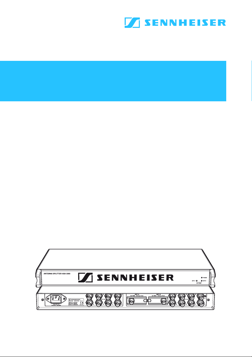
Active Antenna Splitter 2 x 1:8
Instructions for use
ASA 3000
Page 2

Contents
Safety information ......................................................... 3
Delivery includes ............................................................. 3
Operating elements ........................................................ 4
Connection diagram ....................................................... 5
Trouble shooting ............................................................. 9
Accessories .................................................................... 10
Specifications ................................................................ 11
Manufacturer declarations ......................................... 12
Brief description
With the 2 x 1:8 active antenna splitter, up to eight receivers (EM 3031) or twin receivers (EM 3032, EM 3532) can
be operated with only one pair of diversity antennas.
Each diversity section is fitted with a wideband input
module which can be exchanged for a selective input
module. Due to the built-in antenna boosters, the signals
are routed without loss the the connected receivers.
The active antenna splitter allows you to make receiver
syst ems with up to 16 channels.
Areas of application:
y Multi-channel RF installations (fixed or mobile)
y Permanent installations in small conference centres and
similar venues
2
Page 3

Safety information
The 2 x 1:8 active antenna splitter must only be set up and
connected by an electrical engineering expert.
Never open electronic units! This must only be done by
authorized personnel and is all the more important for
units connected to AC outlets. If units are opened by customers in breach of this instruction, the warranty becomes
null and void!
Make sure that the air vents of the unit are not covered or
blocked. Keep the unit away from central heating radiators
and electric heaters!
Set up the unit on an even surface or mount it into a rack!
Lay the cables in such a way that no-one can stumble over
them!
Keep liquids and small parts which conduct electricity away
from the unit! Use a damp cloth for cleaning the unit. Do
not use any solvents or cleansing agents!
Delivery includes
y 1 active antenna splitter, 2 x 1:8
y 1 mains cable
y 1 rack-mounting kit
y 1 set of self-adhesive plastic feet
y 2 telescopic antennas
y 1 instruction manual
For accessories, please refer to page 10.
3
Page 4
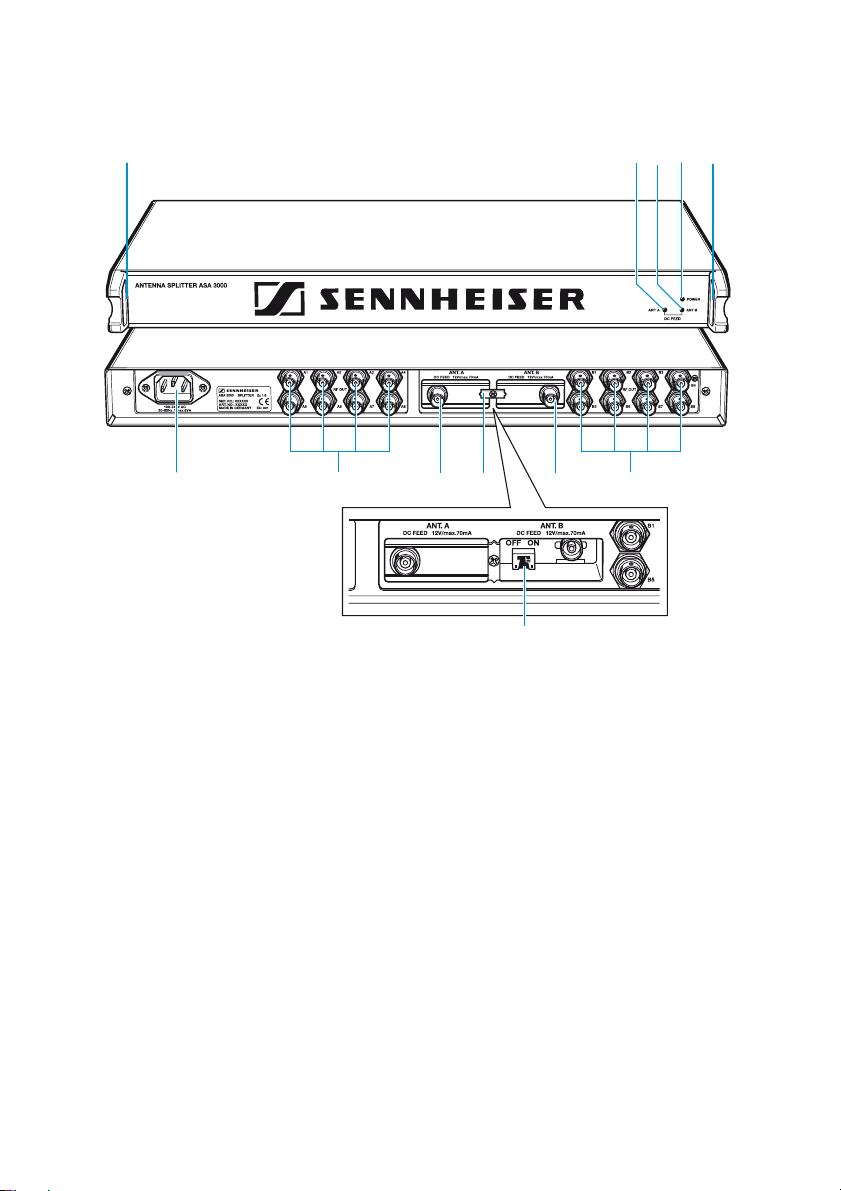
Operating elements
쐇쐃쐋쐏쐏
쐎
쐃 LED DC FEED ANT A (green)
쐇 LED DC FEED ANT B (green)
쐋 LED POWER (red)
쐏 Threaded holes for rack-mounting
쐄 BNC sockets for antenna outputs, diversity section “B”, B1 to B8
쐂 Exchangeable wideband input module with BNC antenna input for diversity sec-
tion “B” ANT. B
쐆 Catch for input modules
쐊 Exchangeable wideband input module with BNC antenna input for diversity sec-
tion “A” ANT. A
쐎 BNC sockets for antenna outputs, diversity section “A”, A1 to A8
쐅 IEC mains socket
쐈 Switches DC-Feed ANT A and DC-Feed ANT B for turning the DC supply voltage for
active antennas and antenna boosters on and off
(switches are located inside the input module slots 쐂 and 쐊)
쐂쐆쐊쐅
쐈
쐄
4
Page 5

Connection diagram
The below connection diagram shows the connections for
an 8 - or 16-c hannel system.
ANT B ANT A
Antenna booster
e.g. AB 1036
Input B
ASA 3000
1 : 8
8 7 6 5 4 3 2 1
Antenna booster
e.g. AB 1036
Mains
Input A
1 : 8
POWER
ANT B
ANT A
1 2 3 4 5 6 7 8
EM 3000
1
B
A
EM 3000
2
B
A
EM 3000
8
B
A
5
Page 6

Putting the unit into operation
Setting up the unit
The unit is suitable for use as table top or can be mounted
into a rack.
왘 Fix the unit to a 19" rack by using the supplied rack-
mounting kit.
왘 To set up the unit on an even, horizontal surface, fix the
four self-adhesive plastic feet to the base of the unit.
Not e:
Some furniture surfaces have been treated with varnish,
polish or synthetics which might cause stains when they
come into contact with other synthetics. Despite a thorough testing of the synthetics used by us, we cannot
rule out the possibility of discoloration, since we don’t
know your furniture. To protect your furniture, we
recommend placing the unit on a non-slip pad.
Connecting the antennas
왘 You can connect the following antenna types to the BNC
sockets and 쐊 of the input modules:
y two GZA 1036 or A 2003-UHF passive antennas or
y two A 12 active antennas or
쐂쐊
y two GZA 1036 passive antennas with AB 1036 antenna
boosters.
The ASA 3000 routes the antenna signals without loss
to the respective antenna outputs.
Not es:
The ASA 3000 is delivered with the DC supply voltage
for active antennas or antenna boosters turned on. The
two LEDs DC FEED ANT A 쐃 and DC FEED ANT B 쐇 light
up green.
쐇쐃
6
Page 7

쐎
쐈
If you use passive antennas only, the DC supply voltage
can be turned off. To do so, remove the two input modules (see “Exchanging the input modules” on page 7) and
set the two switches DC-Feed ANT A and DC-Feed ANT B
쐈 to position “OFF”.
Connecting the receivers
Up to eight receivers, e.g. EM 3031, or eight twin receivers,
e.g. EM 3032 or EM 3532, can be connected.
왘 Use BNC cables to connect the receivers to the BNC
sockets 쐄 and 쐎 as follows:
First receiver:
쐄
Diversity section “A” to A1, diversity section “B” to B1.
Second receiver:
Diversity section “A” to A2, diversity section “B” to B2.
etc.
Connecting the mains cable
왘 Connect the mains cable to the IEC mains socket 쐅 and
to the mains.
The ASA 3000 has no power switch. The unit is ready for
operation as soon as it is connected to the mains.
쐅
Note:
The ASA 3000 can be connected to any mains power
supply with 100 V to 240 V AC (50 to 60 Hz).
Exchanging the input modules
The unit is fitted with two wideba nd input modules (470 to
870 MHz) which are suitable for most applications. However, to ensure optimum reception reliability, we recommend using two selective input modules (60-MHz window)
(see “Accessories” on page 10).
7
Page 8

When using the selective input modules:
y Make sure that all transmitters and receivers of your
transmission system operate within the frequency window of the selective input modules!
When using the wideband input modules:
y Use an active antenna (e.g. A 12 AD antenna) or an
antenna with antenna booster (e.g. GZA 1036 antenna
with AB 1036 antenna booster).
To exchange the input modules:
쐆
쐆
왘 Use a crosstip screwdriver to loosen the screw of the
catch for the input modules 쐆.
왘 To remove the input modules 쐂 and 쐊, plug a BNC con-
nector into the input modules‘ BNC sockets and pull hard
(!) at the BNC connector.
왘 Insert the new input modules and tighten the screw of
쐂쐊
the catch 쐆.
8
Page 9

쐈
Trouble shooting
The LED POWER 쐋 does not light up
The unit is not powered.
Disturbed re ception or no reception
Possible causes:
y Transmitting antennas are not within the reception area
y Transmitters or receivers are not turned on
y Transmitter batteries are not inserted or batteries are
low
y The antennas are not connected correctly
y The connecting cables are defective
y Too high cable attenuation due to too long antenna
cables or wrong type of antenna cable
y The selected transmission and receiving frequencies are
not within the frequency window of the selective input
modules (optional) and antenna boosters (optional)
y When using active antennas or antenna boosters, the
supply voltage must be turned on (see “Connecting the
antennas” on page 6). The two LEDs DC FEED ANT A 쐃
and DC FEED ANT B 쐇 light up green.
If the LEDs do not light up even though the two switches
DC-Feed ANT A and DC-Feed ANT B 쐈 are set to position
“ON”, the antenna inputs are short-circuited.
9
Page 10

Accessories
The following accessories are available from Sennheiser:
Cat. No.
A 2003 UHF Active antenna 03658
A 12 AD UHF Active antenna 04645
GZA 1036 Passive antenna 02243
AB 1036 Antenna booster 03598
IM 3000 Selective input module 05241
GZL 1019 A1 BNC-BNC coaxial cable, length 1 m 02324
GZL 1019 A5 BNC-BNC coaxial cable, length 5 m 02325
GZL 1019 A10 BNC-BNC coaxial cable, length 10 m 02326
10
Page 11

Specifications
RF characteristics / active diversity antenna splitter
Antenna splitter: 2 x 1:8, active
Frequency range: 470–870 MHz
Distribution attenuation: +3/-1 dB
Nominal impedance
of the inputs/outputs: 50 Ω
Connections inputs A/B: BNC sockets
Connections outputs
A1-A8/B1-B8: BNC sokkets
Booster supply 12 V, 70 mA max. each,
at the inputs A and B: short circuit-proof
Overall unit
Supply voltage range: nom. 100–240 V AC,
50–60 Hz
Power consumption: max. 8 VA
Weight: approx. 3 kg
Dimensions: 19", 1 U
Temperature range: -10 to +55 °C
Selective input module (optional)
Variable two-circuit bandpass filter
Frequency range: 470–870 MHz
Insertion lo ss : < 1.5 dB
Bandwidth -1 dB: ≥ 40 MHz
Bandwidth -3 dB: ≤ 60 MHz
Bandwidth -10 dB: ≤ 100 MHz
Far-off selection: ≥ 50 dB
DC feed: max. 0.5 A, 20 V
Input: BNC socket, 50 Ω
Output: IEC connector
11
Page 12

Manufacturer declarations
Warranty regulations
The guarantee period for this Sennheiser product is 24 months from the date
of purchase. Excluded are accessory items, rechargeable or disposable batteries that are delivered with the product; due to their characteristics these products ha ve a shorter service li fe that is principal ly depe ndent on th e indiv idual
frequency of use.
The guarantee period starts from the date of original purchase. For this
reason, we rec ommend that the sales receipt be retained as proof of purchase.
Without this proof (which is checked by the responsible Sennheiser service
partne r) you wi ll not b e reimbur sed for any repairs that are car ried out.
Depending on our choice, guarantee service comprises, free of charge, the
removal of material and manufacturing defects through re pair or replacement of either individual parts or the entire device. Inappropriate usage (e.g.
operating faults, mechanical damages, incorrect operating voltage), wear and
tear, force majeure and defects which were known at the time of purchase are
excluded from guarantee claims. The guarantee is void if the product is manipulated by non-authorised persons or repair stations.
In the case of a claim under the terms of this guarantee, send the device, including acces-sories and sales receipt, to the responsible service partner. To minimise the risk of transport damage, we recommend that the original packaging
is us ed. You r legal rights ag ainst the sel ler, r esulti ng from the con tract of sale ,
are not affected by this guarantee.
The guarantee can be claimed in all countries outside the U.S. provided that
no national law limits our terms of guarantee.
CE Declaration of Conformity
12
This equipment is in compliance wit h the esse ntial requiremen ts and othe r
releva nt p rovis ions of Directive s 1 999/5/E C, 89 /336/EC or 73/2 3/EC. The
declaration is available on the internet site at www.sennheiser.com.
Before putti ng th e device into operation, please observe th e res pective country-s pecif ic r egula tions !
WEEE Declaration
Your Sennheiser product was developed and manuf actured with
highqualit y materials and components which can be recycled and/
or re used. This symbol indicates that el ectrical and ele ctronic
equipment must be disposed of separately from normal waste at
the end of its operational lifetime.
Please dispose of this product by bringing it to your local collection point or
recycl ing centre for such equi pment. This will help t o protect the environment
in which we all live.
Page 13

Sennheiser electronic GmbH & Co. KG
30900 Wedemark, Germany
Phone +49 (5130) 600 0
Fax +49 (5130) 600 300
www.sennheiser.com
Printed in Germany Publ. 06/06 093248 / A02
 Loading...