

Page 1
Active Antenna Combiner
ACA 1
|
Instruction manual
|
|
|
Page 2

Contents
Important safety instructions . . . . . . . . . . . . . . . . . . . 2
The ACA 1 active antenna combiner . . . . . . . . . . . . . . 4
Delivery includes . . . . . . . . . . . . . . . . . . . . . . . . . . . . . . . 4
Product Features . . . . . . . . . . . . . . . . . . . . . . . . . . . . . . 5
Operating controls . . . . . . . . . . . . . . . . . . . . . . . . . . . . . 6
Front side . . . . . . . . . . . . . . . . . . . . . . . . . . . . . . . . . . . . . 6
Rear side . . . . . . . . . . . . . . . . . . . . . . . . . . . . . . . . . . . . . . 7
Putting the ACA 1 into operation . . . . . . . . . . . . . . . . 8
Preparing the ACA 1 for use . . . . . . . . . . . . . . . . . . . . . 8
Using the ACA 1 . . . . . . . . . . . . . . . . . . . . . . . . . . . . . . 12
Example 1: Studio Complex . . . . . . . . . . . . . . . . . . . . 14
Example 2: Large Church . . . . . . . . . . . . . . . . . . . . . . . 15
Cleaning the ACA 1 . . . . . . . . . . . . . . . . . . . . . . . . . . . . 16
If a problem occurs ... . . . . . . . . . . . . . . . . . . . . . . . . . . 17
Accessories . . . . . . . . . . . . . . . . . . . . . . . . . . . . . . . . . . 18
Specifications . . . . . . . . . . . . . . . . . . . . . . . . . . . . . . . . 20
Manufacturer Declarations . . . . . . . . . . . . . . . . . . . . . 21
Contents
1
Page 3

Important safety instructions
Important safety instructions
•Read this instruction manual.
•Keep this instruction manual. Always include this instruction
manual when passing the device on to third parties.
•Heed all warnings and follow all instructions in this instruction manual.
•Clean only with a slightly damp cloth.
•Refer all servicing to qualified service personnel.
Servicing is required if the device has been damaged in any
way, liquid has been spilled, objects have fallen inside, the
device has been exposed to rain or moisture, does not operate
properly or has been dropped.
•WARNING: To reduce the risk of fire or electric shock, do not
use the device near water and do not expose it to rain or moisture. Do not place objects filled with liquids, such as vases or
coffee cups, on the device.
•Only use the NT3-1 table top power supply (see “Accessories” on page 18).
•Do not block any ventilation openings. Install the device in
accordance with the instructions given in this manual.
•Do not install the device near any heat sources.
•Only use attachments/accessories specified by Sennheiser.
Replacement parts
When replacement parts are required, be sure the service technician uses replacement parts specified by Sennheiser or those
having the same characteristics as the original part. Unauthorized substitutions may result in fire, electric shock, or other
hazards.
Safety check
Upon completion of any service or repairs to this device, ask the
service technician to perform safety checks to determine that
the device is in a safe operating condition.
2
Page 4

Important safety instructions
Intended use of the device
Intended use of the ACA 1 includes:
•having read and understood this instruction manual espe-
cially the chapter “Important safety instructions” on page 2,
•using the device within the operating conditions and
limitations described in this instruction manual.
“Improper use” means using the ACA 1 other than as described
in this instruction manual, or under operating conditions which
differ from those described herein.
3
Page 5

The ACA 1 active antenna combiner
The ACA 1 active antenna
combiner
ACA 1 is a compact, cost-effective and easy to deploy antenna
combiner to allow Wireless Microphone coverage over multiple
rooms and large or complex sites such as large churches,
broadcast installations, outdoor sporting events and reality TV
shows.
With the ACA 1 2-channel active antenna combiner, the
received signals of up to four active or passive antennas per
channel can be combined for one receiver or receiver system.
Two channels (A, B) are available.
Multiple ACA 1 units may be combined to cater for systems with
more than four diversity pairs of antennas.
Delivery includes
1ACA1 active antenna combiner
1NT 3-1 mains power supply
2BNC cables 0.5m, 50 ohm
1instruction manual
4
Page 6

Product Features
Product Features
RF function
2 x 4:1 combiner at unity gain
Switchable DC
Supplied on antenna each input for head amplifiers or active
antennas, e.g. AB 3, AB 3700, A12-AD, AB 1036
Switchable RF
RF from each of the eight antenna inputs is switchable to isolate
unused antennas
Visual indication
LEDs indicate input state; RF ON, DC ON and DC LIMIT (current
overload).
5
Page 7
Operating controls
& '() *
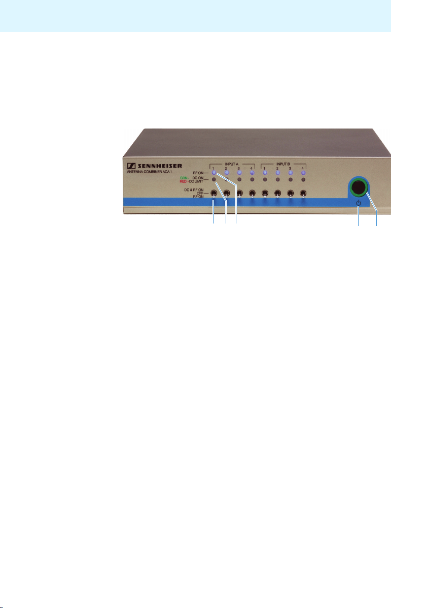
Operating controls
Front side
INPUT A / INPUT B: two groups of identical switches and LEDs
according to the rear side antenna inputs IN A1-IN A4 and
IN B1-IN B4:
! RF ON / OFF / DC & RF ON switch to select active/passive
antennas
" DC ON / DC LIMIT Status LED
GRN (green)- indicates DC ON
RED - indicates DC overload (> 250 mA)
# RF ON Status LED
$ STANDBY button
% Operation indicator
6
Page 8

Operating controls
./0
Rear side
IN A1 to IN A4 / IN B1 to IN B4: 2 x 4 identical antenna inputs
+ IN A1 to IN A4 / IN B1 to IN B4: 2 channels (A, B) with 4 BNC
sockets for connecting active or passive antennas. Each of
these RF inputs can power one active antenna or booster.
, 1 BNC socket OUT A / OUT B per channel for connecting a
receiver or receiver system
- DC IN socket for connecting the NT 3-1 table top power
supply
CAUTION!
Connecting transmitters to the ^cejihdgoutputs can
damage the elec-tronics of the device!
The outputs are provided for connecting receivers. Connecting
the ACA 1 to transmitters will cause malfunction and could
result in permanent damage
!8dccZXidcangZXZ^k^c\VciZccVhidi]Z^cejih#
7
Page 9

Putting the ACA 1 into operation
Putting the ACA 1 into operation
Preparing the ACA 1 for use
! Place the ACA 1 on a flat, horizontal surface.
Please note that the device feet can leave stains on
delicate surfaces!
Mounting the ACA 1 into a 19” rack
CAUTION! Risks when rack mounting the device!
When installing the device in a closed or multi-rack assembly,
please consider that, during operation, the ambient temperature, the mechanical loading and the electrical potentials will be
different from those of devices which are not mounted into a
rack.
! The ambient temperature within the rack must not exceed
the temperature limit specified in the specifications.
! Ensure sufficient ventilation; if necessary, provide additional
ventilation.
! Make sure that the mechanical loading of the rack is even.
! When connecting to the power supply, observe the
information indicated on the NT 3-1 table top power supply.
Avoid circuit overloading. If necessary, provide overcurrent
protection.
! When rack mounting, please note that intrinsically harmless
leakage currents of the individual power supplies may
accumulate, thereby exceeding the allowable limit value. As
a remedy, ground the rack via an additional ground
connection.
8
Page 10

Putting the ACA 1 into operation
2
2
3
4
Rack mounting
one ACA 1
! Unscrew and remove the two recessed head screws (M4x8)
on each side of the ACA 1.
! Secure the rack mount “ears” 1 (supplied with the optional
GA 3 rack adapter) to the ACA 1 using the previously
removed recessed head screws.
! Secure the blanking plate 2 to one of the rack mount
“ears” 1 using two recessed head screws (M 6x10).
! Insert the two blanking plugs 3 into the holes of the
blanking plate.
! Slide the ACA 1 with the mounted blanking plate 2 into the
19” rack.
! Secure the rack mount “ear” 1 and the blanking plate 2 to
the 19” rack.
9
Page 11

Putting the ACA 1 into operation
/0
() *
Connecting devices to the ACA 1
Connecting
the antennas
Active Antennas
The ACA 1 provides two channels A and B. You can connect up
to 4 antennas per channel (diversity). Each input can supply up
to 250 mA for an active antenna.
The supply current for active antennas is limited to
250 mA per input.
Connect the antennas to one of the BNC sockets IN A1…IN A4 +
or IN B1…IN B4.
! Set the switch ! to the correct mode for each connected
antenna:
Switch ! Meaning
DC & RF ON For active antennas
The RF path from the respecting input to
the corresponding output is ON.
The 12V DC supply to the corresponding
input is ON
OFF No antenna connected
RF ON For passive antennas
The RF path from the respecting input to
the corresponding output is ON.
The 12V DC supply to the corresponding
input is OFF
10
Page 12

Putting the ACA 1 into operation
/0
.
Connecting
the receivers
CAUTION!
You can connect two receivers or receiver systems (e.g.
receivers combined via ASA1, ASA3000) to the ACA1. Groups
of daisy-chainded receivers such as :B '%*%!
:B'%%%! or EM
3732 mayalso be connected.
Each receiver system can use up to four diversity pairs of
antennas.
Connecting transmitters to the ^cejih dg outputs can
damage the electronics of the device!
The outputs are provided for connecting receivers. Connecting
the ACA 1 to transmitters will cause malfunction and could
result in permanent damage.
!8dccZXidcangZXZ^k^c\VciZccVhidi]Z^cejih#
! Connect the diversity receiver system to the BNC sockets
OUT A and OUT B ,. Suitable 50 ohm BNC cables are
included in the delivery.
Connecting the ACA 1 to the mains
For powering the ACA 1 and the connected RF boosters or active
antennas you require the NT 3-1 table top power supply (see
“Accessories” on page 18).
Only use the NT 3-1 table top power supply for safe
operation.
! Insert the DC connector of the NT 3-1 table top power supply
into the DC IN socket -.
! Plug the NT 3-1 table top power supply into a wall socket.
11
Page 13

Using the ACA 1
& '
The NT 3-1 table top power supply connection can be
tight fitting at first usage.
Using the ACA 1
Switching the ACA 1 on
! Briefly press the STANDBY button $.
The operation indicator % lights up green.
LED "# Meaning
RF ON # lights up
DC ON # lights up
GREEN
DC ON # lights up
RED
Switch ! is set to RF ON.
The RF
input to the corresponding output
is enabled.
Switch ! is set to DC & RF ON.
The 12V DC supply to the
corresponding input is ON and the
current consumption is lower than
or equal to 250 mA.
Switch ! is set to DC & RF ON.The
12V
corresponding input is ON and the
current consumption is \gZViZg
than 250mA.
The antenna or the connection
cable bVnWZ causing a shortcuit.
The overload indicator lights up
RED.
path from the respectikZ
DC supply to the
12
Page 14

Using the ACA 1
& '
& '
Passive Antennas,
(third party)
Some types of third party passive antennas are a short
circuit at DC by design. When this type of antenna is
used the DC supply to the according inputs should be
switched OFF. If in doubt please check with the antenna
manufacturer.
Setting the ACA 1 to standby mode
! Press the STANDBY button ! for approx. 2 seconds.
! The operation indicator % and the LEDs "# go off. The
ACA 1 switches to standby mode. Connected active
antennas or boosters which are receiving their power from
the ACA 1 are switched off.
Disconnecting the ACA 1 from the mains
The STANDBY button ! does not disconnect the ACA 1 from
the mains. To disconnect the ACA 1 from the mains:
13
Page 15

Using the ACA 1
! Unplug the NT 3-1 table top power supply from the wall
socket.
The ACA 1 is switched off.
14
Page 16

Example 1: Studio Complex
Using the ACA 1
The diagram represents a TV studio complex with three studios
and a newsroom all sharing the same wireless microphone
systems. Four diversity pairs of antennas are deployed, one pair
in each of the areas to be covered.
50 ohm coaxial cables connect each antenna to a centrally located ACA 1 combiner which feeds the radio signal from all of the
antennas to the radio receivers.
Boosters may be required on long cable runs.
The ACA 1 provides 12V DC power at each input to power boosters or active antennas as required.
Coaxial cable types must be chosen with care to avoid excessive
signal loss between the antennas and the combiner.
Position and type of antennas in each area must be chosen with
care to provide appropriate coverage.
15
Page 17

Using the ACA 1
Example 2: Large Church
16
The diagram represents a large Church such as a Cathedral. A
single pair of antennas is unable to provide seamless wireless
microphone coverage due to the size and complex shape of the
building.
Four diversity pairs of antennas are deployed in different areas
of the building at locations chosen by conducting a site survey.
50 ohm coaxial cables connect each antenna to a centrally
located ACA 1 combiner which feeds the radio signal from all of
the antennas to the radio receivers.
Boosters may be required on long cable runs. The ACA 1
provides 12V DC power at each input to power boosters or
active antennas as required.
Coaxial cable types must be chosen with care to avoid excessive
signal loss between the antennas and the combiner.
The type of antennas in each area should be chosen with care to
provide appropriate coverage.
Page 18

Cleaning the ACA 1
Cleaning the ACA 1
CAUTION! Liquids can damage the electronics of the device!
Liquids entering the housing of the device can cause a shortcircuit and damage the electronics.
! Keep all liquids away from the device.
! Do not use any solvents or cleansing agents.
! Before cleaning, disconnect the ACA 1 from the mains
(see page 12).
! Only use a slightly damp cloth to clean the device.
17
Page 19

If a problem occurs ...
Problem Possible cause Possible solution
Active
antennas or
boosters are
not receiving
power
Disturbed RF
reception
If a problem occurs that is not listed in the above table or if the
problem cannot be solved with the proposed solutions, please
contact your local Sennheiser partner for assistance.
Connection
problems
Antennas are
not connected
correctly
Connection cable
is defective
Excessive RF
signal attenuation due to too
long antenna
cable or incorrect
type of antenna
cable
Check the connections of
the NT 3 table top power
supply and/or check the
BNC sockets IN A1 to IN A4
and/or IN B1 to IN B4.
Check the antenna
connections
Replace the connection
cable
Only use the recommended
antenna cable (see “Accessories” on page 18)
or use a shorter antenna
cable
or use a low-attenuation
RF cable
Page 20

Accessories
Accessories
The following accessories are available from your Sennheiser
partner:
Cat. No. Accessory/spare part
503877 NT 3-1 UK Plug-in mains unit 13.8 V/3.4 A - UK version
Mounting material
503167 GA 3 19“ rack adapter
Antennas
502195 A 3700 Omnidirectional antenna with integrated
AB 3700 booster - 470-866 MHz
502197 AD 3700 Directional antenna with integrated AB 3700
booster - 470-866 MHz
002243 GZA 1036-TV Ground plane antenna - 470-800MHz -
adjustable
Boosters
502196 AB 3700 Broadband antenna booster - 470-866 MHz
502567 AB 3-A Antenna booster - 42 MHz switching
bandwidth - 516-558MHz
502568 AB 3-B Antenna booster - 42 MHz switching
bandwidth - 626-668MHz
502569 AB 3-C Antenna booster - 42 MHz switching
bandwidth - 734-776MHz
504680 AB 3-GB Antenna booster - 42 MHz switching
bandwidth - 734-776MHz
502573 AB 3-G Antenna booster - 42 MHz switching
bandwidth - 566-608MHz
003598
AB 1036-TV/UHF Antenna booster - 450-960MHz - 24MHz
19
Page 21

Accessories
Antenna cables (coaxial cable)
002324 GZL 1019-A1 Co-axial cable - 1 m - BNC/BNC
002325 GZL 1019-A5 Co-axial cable - 5 m - BNC/BNC
002326 GZL 1019-A10 Co-axial cable - 10 m - BNC/BNC
505455 GZL 9000-A5 Antenna Cable - 5 m - N-Connectors
505456 GZL 9000-A10 Antenna Cable - 10 m - N-Connectors
505457 GZL 9000-A20 Antenna Cable - 20 m - N-Connectors
GZL 9000 cables require appropriate adapters to BNC.
20
Page 22

Specifications
Specifications
Frequency range 470 to 790 MHz
Gain 0 dB (±3dB)
RF input power max. 10 mW per input
RF connectors BNC female, 50
Supply voltage 13.8 V DC
(with NT 3-1 table top power
supply)
Total current consumption max. 2.5 A
Supply voltage for antennas
or boosters with DC ON
at IN A1 to IN A4 and
at IN B1 to IN B4
Output IP3 > 37 dBm
Output 1dB compression point >20 dBm
Relative humidity 5 to 95%
Operating temperature range –10°C to +55°C
Storage temperature range –20°C to +70°C
Dimensions of housing approx. 212 x 168 x 43 mm
Weight approx. 1170 g
13.6 V DC, 250 mA
overload protected
Ω
21
Page 23

Manufacturer Declarations
Manufacturer Declarations
Warranty
Sennheiser electronic GmbH & Co. KG gives a warranty of
24 months on this product.
For the current warranty conditions, please visit our web site at
www.sennheiser.com or contact your Sennheiser partner.
In compliance with the following requirements
• RoHS Directive (2002/95/EU)
• WEEE Directive (2002/96/EU)
Please dispose of the ACA1 at the end of its operational
lifetime by taking it to your local collection point or
recycling center for such equipment.
CE Declaration of Conformity
•
0682
• R&TTE Directive (1999/5/EU)
The declaration is available at www.sennheiser.com.
Before putting the device into operation, please observe the
respective country-specific regulations.
22
Page 24

Sennheiser UK Ltd.
Pacific House, T
Buckinghamshire, SL7 1EY, Great Britain
www.sennheiser.co.uk
hird Avenue, Globe Park, Marlow,
Pub
l. %*/15
 Loading...