

Page 1

Active T ransmitter Combiner 8:1
Bedienungsanleitung
Instructions for use
Notice d‘emploi
Istruzioni per l‘uso
Instrucciones para el uso
Gebruiksaanwijzing
AC 3000
8
Page 2

Bedienungsanleitung.......................................................................................................3
Instructions for use.......................................................................................................13
Notice d’emploi............................................................................................................. 23
Istruzioni per l’uso..................................... ................................................................... 33
Instrucciones para el uso............................................................................................. 43
Gebruiksaanwijzing.......................................................... ............................................ 53
Page 3
Active T ransmitter Combiner 8:1
Instructions for use
AC 3000
8
13
Page 4

Contents
AC 3000 .................................................................................... 13
Active Transmitter Combiner 8:1 ......................................... 13
Contents .................................................................................... 14
Brief description ...................................................................... 14
Safety instructions ................................................................. 15
Delivery includes ..................................................................... 17
Operating elements ........................................................ ........ 17
Connection diagram ............................................................... 18
Putting the unit into operation .................................... ........ 18
Operation .................................................................................. 20
Troubleshooting ...................................................................... 20
Accessories ............................................................................... 21
Specifications ........................................................................... 21
Garantee ................................................................................... 22
Brief description
With the AC 3000 8-to-1 active transmitter combiner, the
signals of up to eight SR 3054 transmitters or up to four
SR 3056 twin transmitters can be combined onto a single
antenna (A 2003 UHF directional antenna or A 1031 U
omni-directional antenna).
14
The active transmitter combiner allows you to make highquality transmission systems with up to 8 channels.
Areas of application:
y Multi-channel in ear monitoring system for broadcast or
stage use
y Multi-channel system suitable for any application where
talk-back signals are to be transmitted (e.g. studio)
Page 5

Safety instructions
Danger!
Overheating or overvoltages (caused by lightning striking
the mains supply etc.) can cause units with a mains connection to catch fire!
Always set up the unit in a well-ventilated place! Make sure
that the air vents of the unit are not covered or blocked!
Never stack more than two units directly one above the
other! Do not set up the unit near any heat sources and
never expose the unit to direct sunl ight (see p age 15)! U s e
an overvoltage protection or, during a thunderstorm, disconnect the unit from the mains!
The AC 3000 contains mechanically moving parts (fans).
Since dust and pollution can impair their function, you
should regularly check the fans for proper operation and
clean out any dust if necessary. The failure of one or several
fans can cause overheating and permanent damage to the
unit.
Warning!
If you open units or use damaged mains cables, you can
receive a dangerous electric shock!
Never open the unit and only use undamaged mains cables!
If a unit should be defective, repair must be carried out by
authorized personnel! If units are opened by you in breach
of this instruction, the warranty becomes null and void.
Warning!
If units and cables are set up improperly, persons can be
injured or units can be damaged!
Set up the unit on an even surface or mount it into a rack!
Lay the cables in such a way that no-one can stumble over
them!
15
Page 6

Attention!
If liquids or small parts which conduct electricity find their
way into the interior or to the sockets of the unit, this can
cause a short-circuit which may damage the unit!
Keep liquids and small parts which conduct electricity away
from the unit! Use a damp cloth for cleaning the unit. Do n ot
use any solvents or cleansing agents!
16
Page 7

Delivery includes
y 1 active transmitter combiner 8:1
y 1 mains cable
y 1 rack-mounting kit
y 4 set of self-adhesive plastic feet
y 1 instruction manual
You additionally require BNC cables for connecting the
transmitters and the antenna to the AC 3000, an antenna
(A 2003 UHF passive directional antenna or A 1031 U passive omni-directional antenna) and up to eight SR 3054
transmitters or up to four SR 3056 twin transmitters.
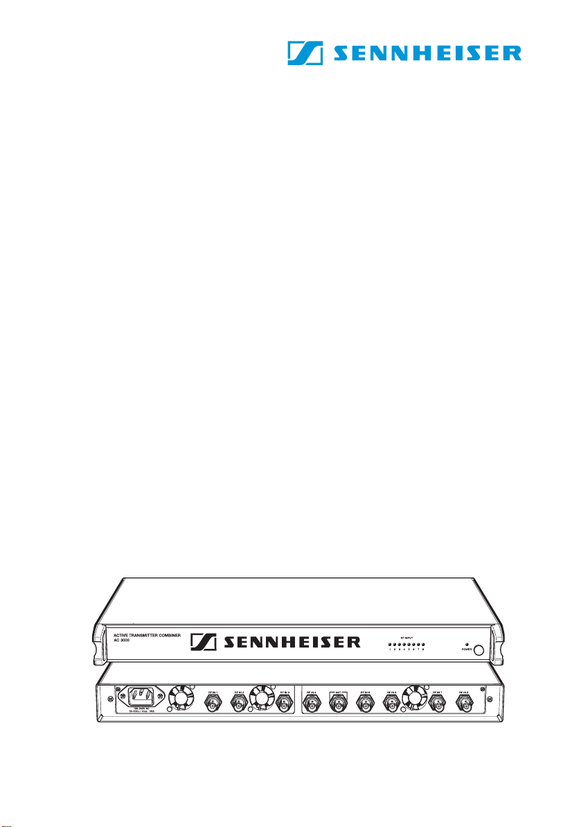
Operating elements
8
POWER LED
POWER (ON/OFF) switch
8 RF inputs RF IN 1 to RF IN 8 for connecting the
transmitters
3 low-noise fans
BNC socket for antenna output ANT
IEC mains socket
8 LEDs for RF signal indication
17
Page 8

Connection diagram
The below connection diagram shows the connections for
an 8-channel system.
ANT
8:1
18
Putting the unit into operation
Setting up the unit
왘 Set up the AC 3000 on an even, horizontal surface so that
it cannot fall over or mount it into a 19" rack.
Warning!
During operation, the AC 3000 and the connected
transmitters produce considerable waste heat! Make
sure that the air vents of the units are not covered or
blocked and provide for a duct of sufficient size to ensure
a free air flow between the units – especially when
mounting several transmitter combiners or transmitters
into a desk, chassis or rack! Never stack more than two
units directly one above the other!
Page 9

Connecting the antenna
The AC 3000 active transmitter combiner can be used with
either the A 2003 U HF dire ctional antenna or the A 1031 U
omni-directional antenna. The antenna transmits the signals of all connected transmitters. The signals are combined
onto the antenna output with no distribution attenuation.
왘 Connect the antenna to the antenna output ANT .
Note:
Each AC 3000 requires its own antenna! Several
AC 3000s cannot be daisy-chained!
Connecting the transmitters
You can connect up to eight SR 3054 transmitters or up to
four SR 3056 twin transmitters to the AC 3000.
왘 Use BNC cables to connect the transmitters to the RF
inputs RF IN 1 to RF IN 8 .
Connecting the mains cable
왘 Connect the mains cable to the IEC mains socket and
to the mains.
Note:
8
The AC 3000 can be connected to any mains power
supply with 100 V to 240 V AC (50 to 60 Hz).
19
Page 10

Operation
Turning the AC 3000 on and off
왘 To turn the AC 3000 on, press the POWER (ON/OFF)
switch .
The POWER LED lights up red.
왘 To turn the AC 3000 off, press the POWER (ON/OFF)
switch once more. The POWER LED goes off.
RF signal indication
왘 The AC 3000 features eight control LEDs which will
light up if an input signal is present at the corresponding
input.
Troubleshooting
One or several LEDs for input signal indication do not
light up
왘 Check if transmitters are connected to the corresponding
inputs.
왘 Check if the corresponding transmitters are turned on.
20
Disturbed reception or no reception
Possible causes:
y Tra nsmit ting antennas are not within the reception area
y Transmitters or receivers are not turned on
y Batteries are not inserted into the receiver or batteries
are low
y The antennas are not connected correctly
y The connecting cables are defective
y Too high cable attenuation due to too long antenna
cables or wrong type of antenna cable
y The selected transmission and receiving frequencies are
not within the frequency window
Page 11

Accessories
The following accessories are available from Sennheiser:
A 2003 UHF Passive directional antenna Cat. No. 03658
A 1031 U Passive omni-directional antenna
Cat. No. 04645
GZL 1019 A1 BNC-BNC coaxial cable, length 1 m
Cat. No. 02324
GZL 1019 A5 BNC-BNC coaxial cable, length 5 m
Cat. No. 02325
GZL 1019 A10 BNC-BNC coaxial cable, length 10 m
Cat. No. 023266
Specifications
Antenna combiner 8-to-1
Frequency range 470 – 870 MHz
Distribution attenuation 0 dB (±1 dB)
RF input power max. 100 mW per input
Impedance 50 Ω
Power supply 100 V – 240 V AC, 50 – 60 Hz
Current consumption max. 120 VA
Temperature range –10 °C to +55°C
Weight 3 kg
21
Page 12

Garantee
The guarantee period for this Sennheiser product is 24 months
from the date of purchase. Excluded are accessory items, rechargeable or disposable batteries that are deli vered with the product;
due to their characteristics these products have a shorter service
life that is principally dependent on the individual frequency of use.
The guarantee period starts from the date of original purchase. For
this reason, we recommend that the sales receipt be retained as
proof of purchase. Without this proof (which is checked by the
responsible Sennheiser service partner) you will not be reimbursed
for any repairs that are carried out.
Depending on our choice, guarantee service comprises, free of
charge, the removal of material and manufacturing defects through
repair or replacement of either individual parts or the entire device.
Inappropriate usage (e.g. operating faults, mechanical damages,
incorrect operating voltage), wear and tear, force majeure and
defects which were known at the time of purchase are excluded
from guarantee claims. The guarantee is void if the product is manipulated by non-authorised persons or repair stations.
In the case of a claim under the terms of this guarantee, send the
device, including accessories and sales receipt, to the responsible
service partner. To minimise the risk of transport damage, we
recommend that the original packaging is used. Your legal rights
against the seller, resulting from the contract of sale, are not affected by this guarantee.
The guarantee can be claimed in all countries outside the U.S. provided that no national law limits ou r terms of guarantee.
22
Page 13

Sennheiser electronic GmbH & Co. KG
30900 Wedemark, Germany
Phone +49 (5130) 600 0
Fax +49 (5130) 600 300
www.sennheiser.com
Printed in Germany Publ. 10/04 93908 / A02
 Loading...