

Page 1

July 2018
Form 8173B www.sencore.com | 1.605.978.4600 Revision 1.3
TSS 6220
Transport Stream Server
User Manual
Page 2

TSS 6220 – User Manual
Page 2 (123)
Copyright
© 2018 Sencore, Inc. All rights reserved.
3200 Sencore Drive, Sioux Falls, SD USA
www.sencore.com
This publication contains confidential, proprietary, and trade secret information. No part of this document
may be copied, photocopied, reproduced, translated, or reduced to any machine-readable or electronic
format without prior written permission from Sencore. Information in this document is subject to change
without notice and Sencore Inc. assumes no responsibility or liability for any errors or inaccuracies.
Sencore, Sencore Inc, and the Sencore logo are trademarks or registered trademarks in the United States
and other countries. All other products or services mentioned in this document are identified by the
trademarks, service marks, or product names as designated by the companies who market those products.
Inquiries should be made directly to those companies. This document may also have links to third-party web
pages that are beyond the control of Sencore. The presence of such links does not imply that Sencore
endorses or recommends the content on those pages. Sencore acknowledges the use of third-party open
source software and licenses in some Sencore products. This freely available source code can be obtained
by contacting Sencore Inc.
About Sencore
Sencore is an engineering leader in the development of high-quality signal transmission solutions for the
broadcast, cable, satellite, IPTV, and telecommunications markets. The company's world-class portfolio
includes video delivery products, system monitoring and analysis solutions, and test and measurement
equipment, all designed to support system interoperability and backed by best-in-class customer support.
Sencore products meet the rapidly changing needs of modern media by ensuring the efficient delivery of
high-quality video from the source to the home. More information about Sencore is available at the
company’s website, www.sencore.com.
All trademarks and registered trademarks mentioned herein are the property of their respective owners.
Page 3

TSS 6220 – User Manual
Page 3 (123)
Revision History
Date
Version
Description
Author
10/31/2017
1.0
Manual for the Sencore TSS 6220
GAK
1/05/2018
1.2
Add Play, Record, Licensing, features to the
TSS 6220 Manual
GAK
07/20/2018
1.3
Add Disaster Recovery and Time Delay
Features
GAK
Page 4

TSS 6220 – User Manual
Page 4 (123)
Safety Instructions
• Read these instructions
• Keep these instructions
• Heed all warnings
• Follow all instructions
• Do not use this apparatus near water
• Clean only with dry cloth
• Do not block any ventilation openings. Install in accordance with the manufacturer’s
instructions
• Do not install near any heat sources such as radiators, heat registers, stoves, or other
apparatus (including amplifiers) that produce heat
• Do not defeat the safety purpose of the polarized or grounding-type plug. A polarized
plug has two blades with one wider than the other. A grounding type plug has two blades
and a third grounding prong. The wide blade or the third prong is provided for your safety.
If the provided plug does not fit into your outlet, consult an electrician for replacement of
the obsolete outlet.
• Protect the power cord from being walked on or pinched particularly at plugs,
convenience receptacles, and the point where they exit from the apparatus.
• Only use attachments/accessories specified by the manufacturer.
• Unplug this apparatus during lightning storms or when unused for long periods of time.
• Refer all servicing to qualified service personnel. Servicing is required when the
apparatus has been damaged in any way, such as power-supply cord or plug is
damaged, liquid has been spilled or objects have fallen into the apparatus, the apparatus
has been exposed to rain or moisture, does not operate normally, or has been dropped.
• Do not expose this apparatus to dripping or splashing and ensure that no objects filled
with liquids, such as vases, are placed on the apparatus.
• To completely disconnect this apparatus from the AC Mains, disconnect the power supply
cord plug from the AC receptacle.
• The mains plug of the power supply cord shall remain readily operable.
• Damage Requiring Service: Unplug this product from the wall outlet and refer servicing
to qualified service personnel under the following conditions:
o When the power-supply cord or plug is damaged.
o If liquid has been spilled, or objects have fallen into the product.
o If the product has been exposed to rain or water.
o If the product does not operate normally by following the operating
instructions. Adjust only those controls that are covered by the operating
instructions as an improper adjustment of the controls may result in damage
and will often require extensive work by a qualified technician to restore the
product to its normal operation.
o If the product has been dropped or damaged in any way.
o The product exhibits a distinct change in performance.
• Replacement Parts: When replacement parts are required, be sure the service
technician uses replacement parts specified by Sencore, or parts having the same
operating characteristics as the original parts. Unauthorized part substitutions made may
result in fire, electric shock or other hazards.
Page 5

TSS 6220 – User Manual
Page 5 (123)
SAFETY PRECAUTIONS
There is always a danger present when using electronic equipment.
Unexpected high voltages can be present at unusual locations in defective equipment and signal
distribution systems. Become familiar with the equipment that you are working with and observe
the following safety precautions.
• Every precaution has been taken in the design of your TSS 6220 to ensure that it is as
safe as possible. However, safe operation depends on you the operator.
• Always be sure your equipment is in good working order. Ensure that all points of
connection are secure to the chassis and that protective covers are in place and secured
with fasteners.
• Never work alone when working in hazardous conditions. Always have another person
close by in case of an accident.
• Always refer to the manual for safe operation. If you have a question about the
application or operation call Sencore for assistance.
• WARNING – To reduce the risk of fire or electrical shock never allow your equipment to
be exposed to water, rain or high moisture environments. If exposed to a liquid, remove
power safely (at the breaker) and send your equipment to be serviced by a qualified
technician.
• To reduce the risk of shock the TSS 6220 must be connected to a mains socket outlet
with a protective earth ground connection.
• For the TSS 6220 the mains plug is the main disconnect and should remain readily
accessible and operable at all times.
• To reduce the risk of shock and damage to equipment, it is recommended that the
chassis grounding screw located on the rear of the TSS 6220 – be connected to the
installation’s rack, the vehicle’s chassis, the battery’s negative terminal, and/or earth
ground.
Page 6

TSS 6220 – User Manual
Page 6 (123)
Table of Contents
1 Introduction ...................................................................................................... 9
2 Specifications ................................................................................................. 10
3 Getting Started ............................................................................................... 12
3.1 Introduction .......................................................................................................................... 12
3.2 Package Contents ............................................................................................................... 12
3.3 Installation ........................................................................................................................... 12
3.4 Rear Panel Connections ..................................................................................................... 14
3.5 Power Connections - Installation ......................................................................................... 14
3.6 Front Panel Features .......................................................................................................... 15
3.7 Obtaining the TSS 6220 IP Address ................................................................................... 16
3.8 Unit Networking and DNS Configuration ............................................................................. 17
3.9 Controlling the TSS 6220 Using the Web GUI .................................................................... 19
3.10 Simplified Startup - Getting a Stream Playing ................................................................... 21
4 Play Control Panel ......................................................................................... 27
4.1 Play Control Panel Overview .............................................................................................. 27
4.2 Stream/PCAP Information Overview ................................................................................... 28
4.3 Player - Adding a Transport Stream .................................................................................... 29
4.3.1 Add Transport Stream - General Configuration ........................................................... 30
4.3.2 Add Transport Stream - Advanced IP Configuration ................................................... 31
4.3.3 Add Transport Stream - File Configuration .................................................................. 32
4.4 Adding a PCAP Play File .................................................................................................... 33
4.4.1 Add PCAP - General PCAP Play Settings ................................................................... 34
4.4.2 Add PCAP - Advanced PCAP Settings........................................................................ 35
4.4.3 Add PCAP - File Play Settings ..................................................................................... 35
4.5 IP Stream and PCAP Status & Configuration Information .................................................. 36
4.6 IP and PCAP Monitor Panel ................................................................................................ 39
5 Schedule Panel .............................................................................................. 41
5.1 Schedule Panel Overview ................................................................................................... 42
5.2 Schedule - Information Fields ............................................................................................. 43
5.3 Adding or Creating a Schedule Configuration - General..................................................... 44
5.3.1 Add Schedule - General Configuration ........................................................................ 44
5.3.2 Add Schedule - Advanced IP Configuration ................................................................ 46
5.4 Schedule Configuration & Information Window .................................................................. 47
5.5 Scheduling Configuration Panel .......................................................................................... 48
5.5.1 Scheduling Configuration Panel - Colors ..................................................................... 49
5.5.2 Scheduling Configuration Panel – Moving Cursor ....................................................... 50
5.5.3 Scheduling Configuration Panel - Loading Event Lists ................................................ 50
6 Delay Viewing Panel ...................................................................................... 51
6.1 Delay Panel Overview ......................................................................................................... 52
6.2 Delay Panel – Receive Fields ............................................................................................. 53
6.3 Delay – Buffer Information Fields ........................................................................................ 54
6.4 Delay – Transmit Information Fields ................................................................................... 55
6.5 Delay – Adding or Creating a Delay Line ............................................................................ 56
6.5.1 Add Delay – General Configuration ............................................................................. 56
6.5.2 Add Delay – Receive Configuration ............................................................................. 57
6.5.3 Add Delay – Transmit Configuration ............................................................................ 58
Page 7

TSS 6220 – User Manual
Page 7 (123)
6.6 Delay Buffer – Extract Buffer To File................................................................................... 60
6.7 Delay Receive Status & Configuration - Information Menu ................................................ 62
6.8 Delay Buffer Configuration – Information Menu .................................................................. 63
6.9 Delay Transmit Status – Information Menu ......................................................................... 64
6.10 Multi Transmit Delay – Tx Delay 2 Configuration .............................................................. 65
7 Disaster Recovery Viewing Panel ................................................................. 67
7.1 Disaster Recovery Panel Overview ..................................................................................... 68
7.2 Disaster Recovery Panel Descriptions ................................................................................ 69
7.2.1 Disaster Recovery Panel – Receive Descriptions ....................................................... 69
7.2.2 Disaster Recovery Panel – Buffer Descriptions ........................................................... 70
7.2.3 Disaster Recovery Panel – Transmit Descriptions ...................................................... 71
7.3 Adding & Configuring a Disaster Recovery ......................................................................... 72
7.3.1 Adding a Disaster Recovery – General Menu ............................................................. 72
7.3.2 Adding a Disaster Recovery – Receive Menu ............................................................. 74
7.3.3 Adding a Disaster Recovery – Transmit Menu ............................................................ 76
7.4 Delay Buffer – Extract Buffer To File................................................................................... 78
7.5 Disaster Recovery – Added Panel Status & Configuration Menus ..................................... 80
7.5.1 Disaster Recovery Receive – Status Information Menu .............................................. 81
7.5.2 Disaster Recovery Buffer – Configuration Menu ......................................................... 82
7.5.3 Disaster Recovery Transmit – Status & Configuration Information Menu ................... 83
7.5 Understanding Disaster Recovery ...................................................................................... 84
8 File Viewing Panel .......................................................................................... 86
8.1 FTP - SMB Loading Play Files to the TSS 6220 ................................................................. 87
8.2 File Transfer Management - User Name and Password..................................................... 89
8.3 Managing Play Files & Folders ........................................................................................... 90
8.4 File Viewing Panel – Filter by Type ..................................................................................... 90
9 Record Panel .................................................................................................. 91
9.1 Record Panel Overview ...................................................................................................... 92
9.2 Record – Information Fields ................................................................................................ 93
9.3 Recording Input TS Stream Configuration .......................................................................... 94
9.3.1 Record Add Transport Stream - Configuration ............................................................ 95
9.3.2 Record Add Transport Stream - IP Configuration ........................................................ 97
9.4 Recording Input PCAP - Configuration ............................................................................... 99
9.4.1 Record Add PCAP - Stream Configuration .................................................................. 99
9.4.2 Record Add PCAP - PCAP Configuration ................................................................. 101
9.5 Record Status & Configuration Information ...................................................................... 102
9.6 IP and PCAP Monitor Panel .............................................................................................. 105
10 Admin .......................................................................................................... 107
10.1 Changing Unit Password ................................................................................................. 108
10.2 Profile Manager ............................................................................................................... 108
10.3 SNMP MIB Files .............................................................................................................. 109
10.4 Diagnostics ...................................................................................................................... 109
10.5 Update the Unit Software Version ................................................................................... 110
10.6 Reboot Unit ..................................................................................................................... 111
10.7 Reset Unit to Factory Defaults ........................................................................................ 111
10.8 General Configuration ..................................................................................................... 111
10.9 Network Port Configuration ............................................................................................. 112
10.10 Licensing Configuration ................................................................................................. 113
10.11 Date/Time Configuration ............................................................................................... 114
Page 8

TSS 6220 – User Manual
Page 8 (123)
10.12 SNMP Communities ...................................................................................................... 116
10.13 SNMP Trap Managers .................................................................................................. 116
10.14 Syslog Configuration ..................................................................................................... 117
11 Reporting Panel ......................................................................................... 118
11.1 Active Alarms .................................................................................................................. 118
11.2 Event Logs ...................................................................................................................... 119
11.3 Configuring the Logs ....................................................................................................... 120
12 About Panel ................................................................................................ 122
Page 9

TSS 6220 – User Manual
Page 9 (123)
1 Introduction
The TSS 6220 Transport Stream Server is the latest in Sencore’s long line of media server
products. It provides robust streaming, recording, time-delay and disaster-recovery capabilities for
customers looking for a simple and cost-effective channel-in-a-box, channel-processing or
storage product.
With the onboard storage and FTP/SMB file management, the unit can take stored media files
and play them out according to user-supplied schedules for channel creation or en-masse for
network testing and lab use. The recording option makes it easy to schedule and make captures
for later playout or analysis.
The time-delay and disaster-recovery options provide intuitive time-shifting and long-term storage
/replay capabilities with incredibly simple setup, configuration and status monitoring. Enhanced
features like multiple delays from the same buffer and automated disaster-mode activation make
the TSS 6220 usable in a huge variety of applications.
With its intuitive web UI, full web API remote control, and SNMP capabilities, the TSS 6220 offers
users a simple, reliable and powerful solution for operational and lab environments. The TSS
6220 has multiple rackmount chassis options ranging from 1RU to 3RU depending on storage
space requirements. The system also includes redundant power supplies, multiple network ports
and has numerous available expansion options.
This manual provides startup and operational information. It is written for professional operators
of video distribution systems and assumes a prerequisite level of technical knowledge.
Page 10

TSS 6220 – User Manual
Page 10 (123)
2 Specifications
INTERFACES PHYSICAL
Included IP Ports: 2x RJ45 1Gbps (Each port can be used for streaming and/or
management)
Optional IP Ports: Additional 2x RJ45 1Gbps Fiber 2x SFP 1/10Gbps
ASI I/O (Future Option): 2x Input Ports (75ohm BNC) 2x Output Ports (75ohm BNC)
FORMATS INPUT AND OUTPUT
IP Input Formats: UDP or RTP - RTP Header Extensions Supported
IP Output Formats: UDP or RTP
IP Encapsulation: 1 to 7 TS Packets per IP Packet
IP Addressing: Unicast or Multicast
IGMP Compatibility: Version 1, 2 & 3
IP Bitrates: 250 Kbps to 200 Mbps
File Types: Transport streams (.ts, .trp)
PCAP Ethernet capture (.pcap)
MANAGEMENT
Protocols: HTTP and SNMP
User Interfaces: Full control via web GUI
Automation Interfaces: Full status and control via SNMP, Configurable SNMP traps, Web
services API available, Syslog message logging
Firmware Updates: Via web GUI
POWER
Voltage: 100-240V
Frequency: 50-60Hz
Power Redundancy: Dual, hot-swappable supplies
CHASSIS OPTIONS
TSS 62220: 1RU chassis suitable for streaming, scheduled playlists and simple recording
TSS 62221: 1RU chassis suitable for time-delay, disaster-recovery and extended recording.
TSS 62222: 2RU chassis suitable for time-delay, disaster-recovery and extended recording.
Size: Rack-mount 1 RU chassis (2RU for TSS 62222 option)
1RU Chassis Depth: 20 inches (507 mm)
Physical chassis dimensions and operating conditions vary depending on chassis and
storage selection
Page 11

TSS 6220 – User Manual
Page 11 (123)
STORAGE OPTIONS
SSD Hard Drives:
Intended Use: Streaming and playlists High-performance recording
Cumulative Performance: 1Gbps+ for streaming-only 300-400Mbps for time-delay and
disaster-recovery
Redundancy Configuration: RAID-5 for time-delay and disaster-recovery
SAS Hard Drives:
Intended Use: Long-term storage for time-delay disaster-recovery and recording
Cumulative Performance: 200-250Mbps for time-delay and disaster-recovery
Redundancy Configuration: RAID-6 for time-delay and disaster-recovery
Feature: MPEG over IP Schedule Playout
Schedule MPEG transport streams to play out
Manually create schedule in UI or upload schedule file
Gap mode setting to fill open time in schedule
Feature: MPEG over IP Streamer- Play Option
Full line rate streaming
PCAP, MPEG transport stream files supported
Seamless looping
Full transport parameters control (IP addresses, UDP ports, RTP)
Feature: MPEG over IP Recording Option
Capture to PCAP, MPEG transport stream files supported
Immediate record start or scheduled start
Full transport parameters control (IP addresses, UDP ports, RTP)
PCAP filtering
Feature: MPEG over IP Delay Playout(s) Options
Define source multicast(s) for delay and output multicast(s)
Define delay time or length of each delay
Define IP port(s) for each delay
Feature: Disaster Recovery Option
Define archive IP source and disaster playout multicast
Define segment size for archiving live content (Example 1 day),
Automatically manage segment archiving size
Define Disaster conditions and timeout delay
Loop playout segment during disaster
Specifications are subject to change without notice.
Page 12

TSS 6220 – User Manual
Page 12 (123)
3 Getting Started
3.1 Introduction
This section provides an overview of what is included with your TSS 6220. It provides critical
information on obtaining the unit’s IP address in which to gain access to the unit’s web interface
GUI. It provides front/rear panel descriptions and information on getting the unit mounted in a
standard rack.
3.2 Package Contents
The following is a list of the items that are included with the TSS 6220 unit:
1. Startup Guide
2. AC Power Cord
3. Rackmount Rails
If any of these items were omitted from the packaging of your unit, please call
1-605-978-4600 to obtain a replacement.
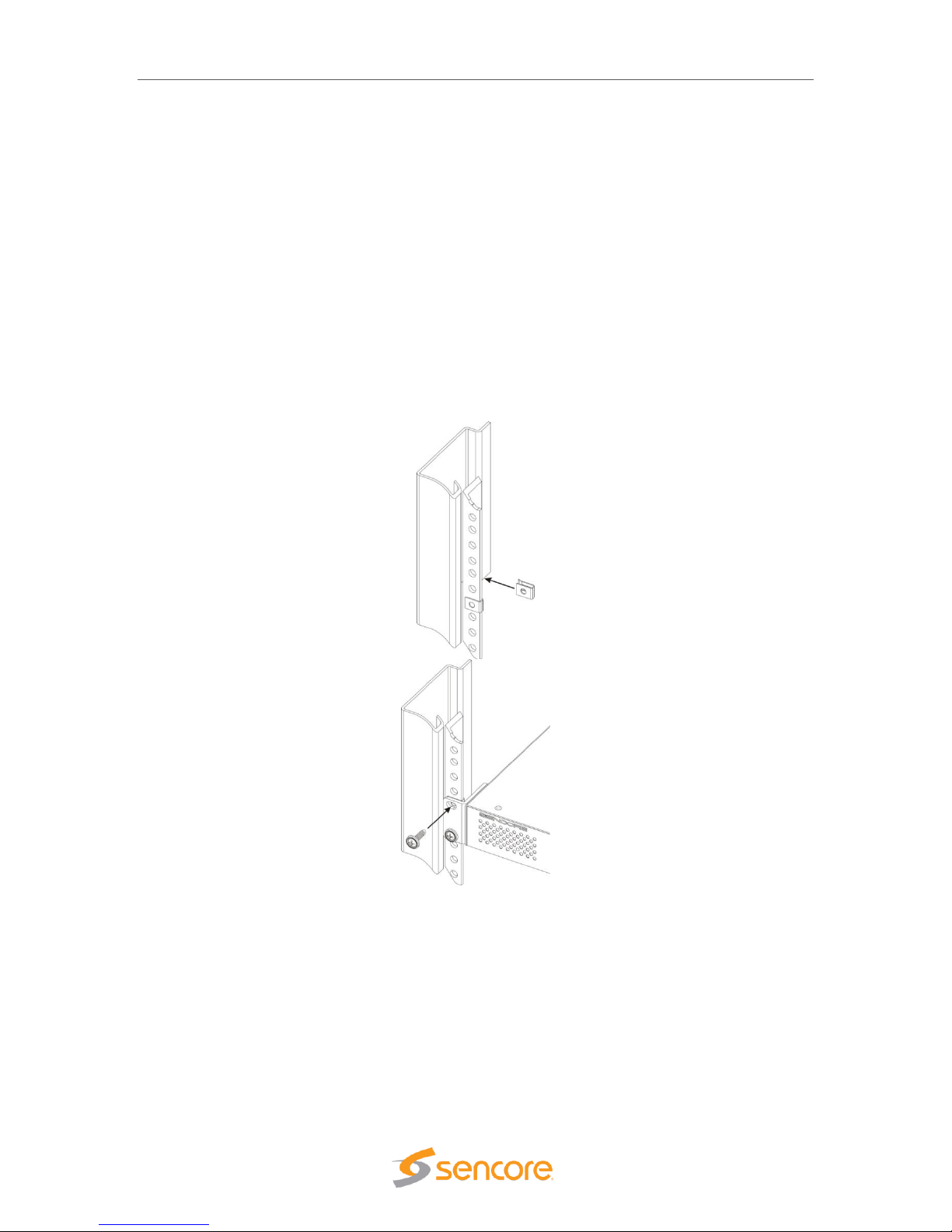
3.3 Installation
The TSS 6220 rackmount chassis is a 1RU or 2 RU enclosure that is designed to be mounted in
a standard 19” equipment rack. The unit is shipped with the mounting hardware necessary to
safely secure the chassis in the rack. This includes rackmount ears and screws for the front along
with rails to support the sides. The user is advised to always use the included rails for mounting.
Page 13
TSS 6220 – User Manual
Page 13 (123)
The TSS 6220 is designed for front-to-back ventilation. Care must be taken to ensure that this
ventilation is not impeded in any way.
To install the TSS 6220 into a rack use the following steps:
1. Determine the desired position in the rack for the TSS 6220 making sure that the air
intake on the front of the unit and the exhausts on the rear of the unit will not be
obstructed.
2. Insert the rack mount clips into place over the mounting holes in the rack.
3. Slide the TSS 6220 into position in the rack.
4. Secure the TSS 6220 to the rack by installing the four screws through the front mounting
holes and tightening.
WARNING: To prevent injury, the apparatus must be securely attached to the floor/wall in
accordance with the installation instructions.
The TSS 6220 is designed for front-to-back ventilation. Care must be taken to ensure that this
ventilation is not impeded in any way.
Page 14

TSS 6220 – User Manual
Page 14 (123)
3.4 Rear Panel Connections
All of the external connections for the TSS 6220 are located on the rear of the unit. These
connections include standard computer I/O (Monitor, USB, parallel, serial, audio, and LAN ports)
and the TSS 6220 IP output connections. The power connection is also located on the rear of the
unit. The following provides an overview description of the rear panel connections and features.
Descriptions:
1. Power Connector: Provides AC power connection for powering the system
2. IPMI Port: Can be used for remote server management, but not normally used in the
TSS 6220 operation
3. eth0 Port: Network port for management and streaming/recording
4. eth1 Port: Network port for management and streaming/recording
5. eth2 Port: Port available only with the addition of optional card adding either 2x RJ45 or
2x SFP ports
6. eth3 Port: Port available only with the addition of optional card adding either 2x RJ45 or
2x SFP ports
7. VGA Monitor Output
8. USB Interface Ports
9. RS-232 Port
3.5 Power Connections - Installation
Using the proper power connections is vital to the safe operation of the TSS 6220. Only use the
supplied 3-prong power connectors or those with equal specifications. NEVER tamper with or
remove the 3rd – prong grounding pin on any cord. This could cause damage to the unit,
personnel, or property.
The TSS 6220 is intended for use on either 120V or 240V systems. The power supply will
automatically detect the voltage to which it is connected. There is one power supply and one AC
power cord. To connect AC power, perform the following:
1. Locate the proper AC power cord.
2. Plug the female end of the power cord (end with no prongs) into the back of the unit.
3. Plug the male end of the power cord into a proper protected AC outlet.
6
9
8
235
4
Page 15

TSS 6220 – User Manual
Page 15 (123)
3.6 Front Panel Features
The front panel contains some pushbuttons and indicator lights. This section provides an
overview of these features.
*NOTE: Some design modifications may occur in which features shown in this image and
described below may not be found on your TSS 6220.
Front Panel Descriptions:
1. UID: Pushbutton: This pushbutton provides an identification light at the rear of the unit.
Press the UID pushbutton to turn on a blue light at the rear of the unit. This makes it easy
to identify the unit when viewing from the back of the equipment rack. The “I” light on the
front panel (#8) indicates when the UID is switched on.
2. Reset Pushbutton: This pushbutton provides a reset of the system. Press and release to
initiate a reset operation of the operating system.
3. Power Pushbutton: Turns the unit AC power on and off. Hold down for 3 seconds and
release to power the unit on or off.
4. Power Light: Indicates when the unit is powered on for normal operation.
5. Hard Disc Drive Light: Indicates normal OS unit disc drive activity.
6. Network Port Indicator Light: Indicates normal unit network port data activity.
7. Network Port Indicator Light: Indicates normal unit network port data activity.
8. i Indicator Light: This light provides an indication when the UID feature is turned on
illuminating a blue light at the rear of the unit.
3
8
2
1
4
Page 16

TSS 6220 – User Manual
Page 16 (123)
3.7 Obtaining the TSS 6220 IP Address
Operating the TSS 6220 depends on gaining access to the unit’s network GUI as there is no front
panel interface. Connecting to the unit’s web GUI using a web browser requires knowledge of the
IP address of the port in which to enter into the address field of a web browser. To acquire and or
to change the port’s IP address from the factory default requires viewing a computer monitor
connected to the unit along with the use of a keypad to navigate the provided menus.
To obtain or make changes to the port’s IP address:
1. Connect a computer monitor to the VGA
connector and power it on. Reference
Section 3.4 in this manual – (#7) rear panel
port.
2. Connect a PC keyboard (USB type) to the
rear panel USB connectors. Reference
Section 3.4 in this manual – (#8) rear panel
USB connection ports.
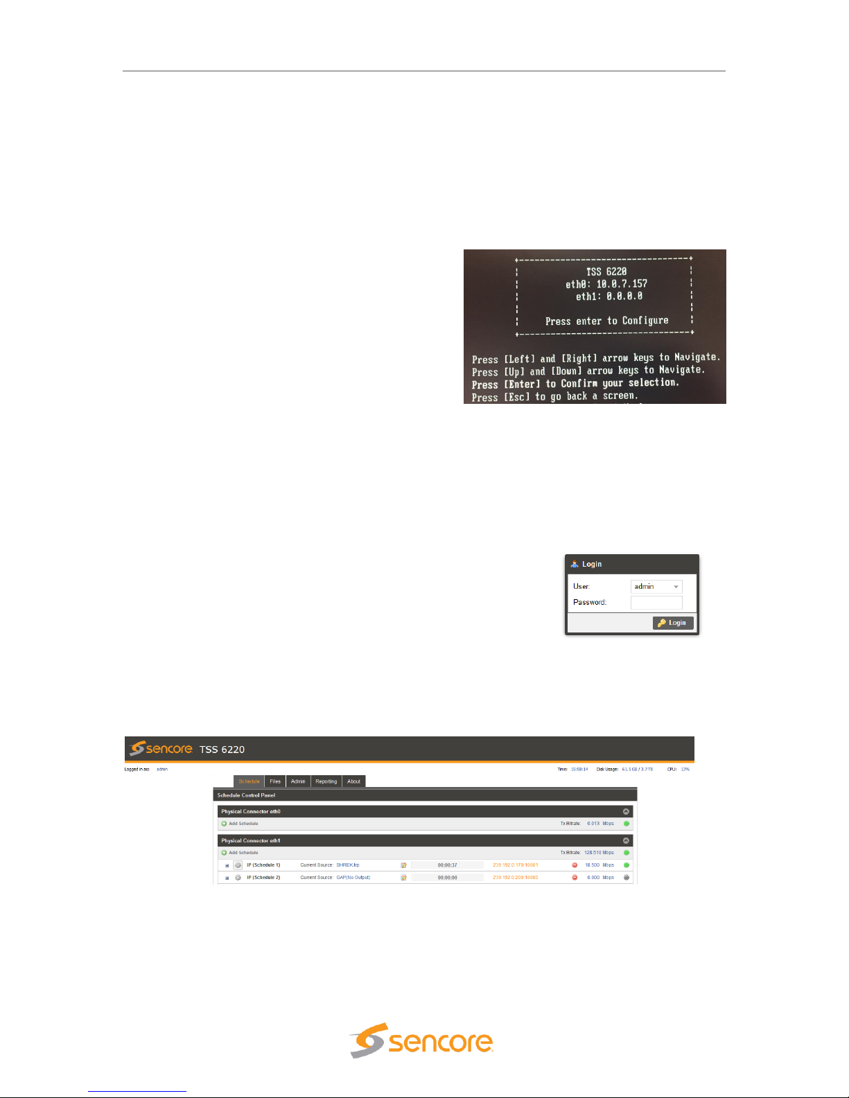
3. With power properly connected to the TSS 6220, push and release the front panel power
button. Allow some time for boot up. The system
starts up with no user or password entry required.
A Main Menu screen appears on the monitor
.
4. The Ethernet port 0 (eth0) and Ethernet port 1
(eth1) IP addresses are shown on the initial Main
Menu. Enter the IP address of the port you are
using into your web browser. See the next sections
(3.7, 3.8) of this manual for more details on
changing the IP address and using the web GUI.
5. If the IP addresses are not shown, press the ENTER key on the keyboard to advance to
the next menu. Press the Up or Down arrow keys on the keyboard to select the eth1 or
eth0 Adapter Status listing by Moving the cursor in
front of the selection. Note: If no cursor is seen, press
ENTER a second time.
6. Press Enter on the keyboard to advance to the
configuration menu if you wish to change the IP
mode (static or DHCP) or to change IP Address,
Subnet, or Gateway addresses. See the next
section in this manual for additional information.
In some instances, you may be able to use the factory default IP addresses to gain web access.
The following default IP addresses are used.
Factory Default Settings:
eth0: DHCP
eth1: 10.0.0.61
eth2: 10.0.0.62 (with added optional ports)
Page 17

TSS 6220 – User Manual
Page 17 (123)
3.8 Unit Networking and DNS Configuration
The TSS 6220 network configuration is managed with setup menus visible by connecting a
computer monitor and USB keypad to the system. The configuration menus provide entry of host
names, gateway and DNS server addresses. Setup of the unit’s Ethernet ports including if they
are static or DHCP configured. If static, entry of the ports IP address, gateway and subnet may be
entered. This section shows the typical setup menu features and describes how to setup the
network settings.
Viewing the setup utility screens provided by the TSS 6220 requires connecting a computer
monitor to the VGA video output connector on the rear of the unit. It requires the use of an USB
keypad. View the monitor screen and use the keypad for navigation and entry. The following
navigation and entry rules are used and included as a reminder on each setup screen.
Press [Enter] to confirm a selection – advance to next menu/selection
Press [Esc] to go back to previous menu and accept entries
Press [Left] and [Right] arrow keys to navigate
Press [Up] and [Down] arrow keys to navigate
Press number and letter keys for field input values
Press [Del] and [Backspace] as needed for text entry
Configure Networks Settings
Network configuration settings are available to enter a unit host name, define a gateway and
enter primary & secondary DNS addresses. These selections are available in the “Configuration
Networks” menu.
1. From the opening menu – press the ENTER key.
2. Position the cursor in front of Configure Networks selection as in illustration below. Press
the ENTER key to advance to the Network Configuration Menu.
3. To enter a Host Name: Position the cursor in front of the Host Name row using the up
and down arrow keys. Press ENTER. The first field is selected for letter or number entry.
Enter the number or letter. Press left or right arrow key to move to the next digit. Press
ENTER key.
4. To enter a Default Gateway: Position the cursor in front of the Default Gateway row.
Press Enter. Enter the desired gateway. Press ENTER.
5. To enter a Primary and/or Secondary DNS: Position the cursor in front of the Primary
DNS and/or Secondary DNS row to be changed or entered. Press the ENTER key. Enter
the address using number keys while navigating with the arrow keys. Press ENTER.
Page 18

TSS 6220 – User Manual
Page 18 (123)
Ethernet 0 and Ethernet 1 Port Configuration Changes
Network configuration settings are available to enter a static IP address, gateway address and
subnet mask for Ethernet port 0 (eth0) and Ethernet port 1 (eth1). These selections are available
in the respective “eth1 Adapter Status” menu and “eth0 Adapter Status” menus. The following
describes the steps to enter or change a port’s static IP address.
1. From the start menu, press the ENTER key to advance to the Unit Networking screen.
2. Press the Up or Down arrow key as needed to move the cursor position in front of the
eth0 or eth1 row. Press the Enter key to advance to the Adapter Eth Status menu.
3. Use the up and down arrow keys to position the cursor in front of the IP Mode row. If it
shows DHCP - Press the ENTER key to select the setting field. Click the up or down
arrow key to increment setting to “Static.” Press ENTER.
4. Use the up and down key to position the cursor in front of the IP Mode row. Press
ENTER to enter the field. Enter number values to define the desired static IP address.
Use the left and right arrow keys to move to different digits. Press ENTER when
complete.
5. Change Mask and Gateway settings using the same technique as in step 4. Press the
ENTER key when finished to accept entries and return to the menu.
Page 19

TSS 6220 – User Manual
Page 19 (123)
3.9 Controlling the TSS 6220 Using the Web GUI
Controlling the TSS 6220 is done by a network connection to either the eth0 or eth1 ports and the
use of the web interface or GUI. From any PC that is connected to the same network as the TSS
6220, open a web browser application and type the IP address of the unit in the address field.
You must obtain the unit IP address with the procedure in the Startup section 3.7 on page 16.
When connecting to the web GUI, you are greeted with a Login screen as shown below. The
default user field entry is admin and the default password field is left blank or no entry. Press the
login button in order to login to the web interface. The User and Password can be changed for
improved security in the Admin section of the GUI. Please see section 10.1 in this manual.
When connected you are greeted with the home or start page of the web GUI as shown below.
Depending on the options and licensing some variations in the screen may be seen.
To open the TSS 6220 web interface use one of the following supported browsers.
• Internet Explorer version 9 or newer
• Firefox
• Google Chrome
• Microsoft Edge
The user is capable of configuring parameters from this page by clicking on the selection tabs at
the top of the page below the Sencore TSS 6220 header. User configuration changes are offered
in each section by clicking on the (cog) which represents a settings configuration is
available for the listed item. Each section contains a dropdown icon which is used to collapse
or expand a section to see additional details. Further details of the common fields in the web GUI
of the TSS 6220 are described
The top section or fields of the TSS 6220 web GUI includes login and operational information of
the system. Below is a reference to the information provided by each field.
Page 20

TSS 6220 – User Manual
Page 20 (123)
1. Logged in as: This field indicates the logged in user. This field may not be selected or
changed. The User and Password may be set in the Admin tab. See section 6.1.
2. Selection Tabs: Provides operational control of the TSS 6220. Click on a tab to select.
The tabs shown and available for selection depend on unit licensing.
3. Storage Disk Usage: Indicates actual disk size that is currently in use
4. Storage Disk Usage: Indicates total disk size available for use
5. CPU: Indicates the percentage of CPU usage
6. Logout: Provides quick logout, click to log out from the MIP GUI.
Field
Button/Selections
Description
1. Logged in
as:
Admin (Default)
Shows the logged in user name. A view only field.
2. Selection
Tabs
Play
Files
Record
Schedule
Admin
Reporting
About
Provides control for playing stream and PCAP files
Provides viewing of media disc play files
Provides record captures of TS streams or PCAP
Provides for schedule playout of TS streams
Provides administrative tasks
Provides reporting and logging
Provides unit information
3. Disk
Usage
Example shown: 63.0
GB
Indicates the disc drive memory space that is
currently being used by the system
4. Disk
Usage
Example shown:
3.7.TB
Indicates the total disc drive memory space
available for TS and PCAP stream storage
5. CPU
Example shown: 13%
Indicates percentage of CPU processing capacity
that is in use.
6. Logout
Click on
icon
Click to log out of the web GUI connection to the
TSS 6220
3
456
1
2
Page 21

TSS 6220 – User Manual
Page 21 (123)
3.10 Simplified Startup - Getting a Stream Playing
This section provides a quick start process to assist you in getting an output stream playing to the
Ethernet 1 port. This section provides only enough information to get you outputting a TS stream.
It is not intended to completely summarize all the information contained in this manual. Please
reference other portions of the manual to answer questions and become familiar with the TSS
6220 and its features.
Get Unit Powered & Network Connected:
1. Locate the TSS 6220 in a convenient location or mount in an equipment rack in which AC
power and a connection to the network is closely available. Connect an AC cord from the
rear of the unit to the AC outlet.
2. Connect a network cable between the Ethernet port 1 (Port nearest the VGA video
connector on rear panel) and to your network.
3. Momentarily press the Power button on the unit front panel. You will observe and hear
normal PC startup activities. The front panel power light should illuminate and drive light
activity indicated. Wait while the unit boots up.
Establishing a Web Connection with the Pre-Set Management IP Address
To access the TSS 6220 web user interface, it is necessary to establish an Ethernet connection
to the device. There are two alternative ways to connect to the TSS 6220’s management IP
address: 1.) Use the pre-set management IP address or 2.) Connect a monitor and keyboard to
the server to retrieve the IP address. The following steps describe how to use a pre-set
management IP address on a PC via a connection to the Eth1 port.
The TSS 6220 is shipped with the following factory settings for the Eth1 network ports.
Eth1 Default IP address:
10.0.0.61
You can connect to the web UI
of the TSS 6220 using a PC and
connecting directly from the
PC’s network port to the Eth1
port with an Ethernet cable.
Configure the PC’s network port
settings to permit a direct
connection.
For Windows, the network
parameters are set in the
Control Panel — Network and
Internet — Network and
Sharing Center — Network
Connection — Properties —
Internet Protocol Version 4
Properties viewing menu.
Select the user defined address, and set the PC’s IP address to 10.0.0.60 and the subnet mask
to 255.255.0.0.
When the IP address of the PC has been set in the same subnet as the TSS 6220’s factory
setting, a web browser can be used to access the web user interface at 10.0.0.61.
Page 22
TSS 6220 – User Manual
Page 22 (123)
Retrieve and/or Configure the Unit IP address
You can determine the TSS 6220’s IP address of both Eth0 and Eth1 ports by connecting a
monitor and keyboard to the server. All configuration of the TSS 6220 is done via a PC and web.
The Ethernet port 1 can serve both as a management port for web browser access and as the
streamer IP/PCAP network port. The following section describes how to connect a monitor and
keyboard to the server to retrieve and/or change the unit’s IP address on both ports. To connect
to the unit’s web browser:
1. Connect a computer monitor to the TSS
6220. Connect a VGA video cable from the
VGA connector at the rear of the TSS 6220
to the computer monitor. Power up the
computer monitor. Connect a PC USB
keyboard to one of the USB ports at the rear
of the TSS 6220. The display screen on the
monitor will indicate the current IP address
for the Ethernet 1 port (eth1). It also shows
the IP address for the other Ethernet 0 port
(eth0)
2. If you do not have a computer monitor you may try to access the web GUI as described
in the previous page using the factory default IP settings shown below:
Ethernet port 0 (eth0): 10.0.0.61
Ethernet port 1 (eth1): 10.0.0.62
Use PC Web Browser to Connect to the TSS 6220’s Web GUI
1. Connect a PC to the same network as the TSS 6220. Open
a web browser application on the PC and in the top address
field enter the IP address of the eth1 port as found in the
previous step.
2. The Login screen appears with a successful connection.
The default User name is admin and the default password is blank or no entry. Click on
the Login field.
When successfully logged in the web connection to the GUI produces a Schedule Control Panel.
A Play Control and/or Record Panel may be shown depending on unit licensing.
Use FTP or SMB to Load Stream/PCAP Files to Media Storage Drives
The TSS 6220’s media drives are available to store files used for playout in a schedule. Click on
the “Files” tab at the top of the GUI to view available files. If a file is available for selection, click
on the Schedule tab and skip to the instructions “Creating a Play/Event Schedule” instruction
section.
Page 23

TSS 6220 – User Manual
Page 23 (123)
If no files are available you will need to access and use FTP or SMB to load files to the media
drive. Read on in this section for details on accessing FTP and loading files/folders. Using FTP
requires starting an instance of Windows Explorer on your PC and entering the address of the
FTP server. Follow the instructions below.
The FTP server address is located in the
File Viewing Panel (Files tab) in the TSS
6220’s web GUI. Look near the top of the
page under the Files Control Panel
header. (See circle in illustration) Click at
the end of the field and drag the mouse
to highlight the ftp address. Copy the
address – (Keyboard Ctrl-C key
sequence).
Open a Windows Explorer application window on your PC. In the header of this application –
paste in the ftp address listed in the TSS 6220’s
File menu on the second line below the Files
Control Panel heading. Paste the ftp address –
(Ctrl-V) as shown in the example figure.
Example shown: ftp://10.0.15.60.
Press the Enter key on your keyboard.
Upon connection to the ftp server you will be prompted for a
username and password: Below is the default User and
Password. The Username/Password can be set - see section 8.2 for
instructions.
User: root
Password:
Note: The Password field is left blank or no entry as shown.
Click on the Log On field to access the FTP server.
Upon connection to the ftp server
you can view the current folders
and play files in the TSS 6220.
To transfer files to the ftp server,
you may use common window’s
based file copy and paste
techniques or drag and drop
techniques. For example, open a
2nd version of Windows Explorer application. (Right mouse click on the Windows Explorer icon at
the bottom system tray – click on Windows Explorer) You now have both the FTP server window
and the Windows Explorer application running. Position both the FTP window and the Windows
Explorer windows beside each other on your PC screen. See example below. Click on a file or
Page 24

TSS 6220 – User Manual
Page 24 (123)
folder in the Windows Explorer window and drag it into the right side of the FTP server window.
The folder or file is transferred as illustrated below.
Creating a Play/Event Schedule
If licensed for the Schedule playout capability, you can create a play schedule to produce a
playout stream. To create a schedule click on the Schedule tab and then click on the
icon. Note that this selection is available for each of the Ethernet ports.
A Configure IP menu opens to a General configuration
menu. You may enter an alias name or use the default
name. Select a Gap Mode using the dropdown selections in
this field. The Gap Mode defines what you want to happen in
the output between scheduled stream playout events. If you
choose “Default File,” click the Browse field and select a TS
file to playout during gap periods. Define the IP Ethernet
port, Destination IP address and port. Click the Apply field at
the bottom to create the schedule.
The created schedule is shown as a listing or row. There can
be up to 16 different schedules or rows. To define the
playout streams, dates, and times in a schedule, click on the
icon to select the Scheduling Configuration Panel.
Page 25

TSS 6220 – User Manual
Page 25 (123)
Click the icon to add a timed event or stream to the playlist. Browse and select the TS
file you wish to create as a playout event. The file loads as a row into the schedule and default
times and dates are generated. Click in the Start Date, Start Time, or Time Slot Duration fields to
change these default values. Listings are show according to date and times in the schedule. See
Section 5 in this manual for more details.
To start a file or event playing out immediately in a schedule, click on the Start Date field and
enter the current date. Click on the Start Time field and enter a start time that is only a few
seconds from the current time. You may need to check and/or adjust the current time of the
Server. The current date/time is shown and set under the Admin tab in the Date/Time section.
See the Admin section of this manual for more details. Once the start time is reached, the event
begins playout on the specified Ethernet port.
In Play Control Panel Add a Transport Stream
The TSS 6220 web GUI may include a Play tab, if licensed for the Play out feature. To create or
add a playing stream to the IP output on the Ethernet 1 port, click on the icon below
the Physical Connector eth1 heading. An Add Transport Stream menu opens and defaults to the
General tab.
Configure the Output Stream
The General configuration menu provides selections defining the
output IP stream and IP destination address and ports. Select a
source file for playout. Click on the Browse field and navigate to
the file you wish to select for playout. Open the file. It will populate
the Source listing with your file name.
Define the IP parameters. The Physical Connector field should
indicate eth1. If not, select the dropdown and select eth1. Click on
the Destination IP field and enter the destination address. Enter a
Destination Port in the Destination Port field. Click on the Apply
box at the bottom of the menu to add the stream to the Ethernet
port 1 (eth1) output.
Page 26

TSS 6220 – User Manual
Page 26 (123)
Start the Output Stream Playing
After the stream is added you will see the stream listed in the Physical Connector eth1 section of
the Play Control Panel. If you don’t see the listing click on the Show/Hide icon . Click on the
Play icon to begin producing the stream output. The light at the far right turns green and the bit
rate field beside it begins to show the output transport stream bitrate. The stream time begins to
increment and the blue highlight advances from the left (start) to the right (end) in the center
progress window.
Your selected stream is now outputting to the network. Click on the cog wheel icon to make
changes to the stream output configuration. You may also click on the icon to bring up a
configuration and monitoring panel. It provides a shortcut to improve viewing and playout
statistics while offering some convenient control options.
Page 27

July 2018
Form 8173B www.sencore.com | 1.605.978.4600 Revision 1.3
4 Play Control Panel
The play feature is a licensed feature of the TSS 6220. When licensed, the Play tab is shown and
available to select. Selecting or clicking on the Play tab advances the GUI to the Play Control
Panel. The Play Control panel provides management of TS stream files and PCAP files that are
manually configured for playout from the TSS 6220. This panel manages each of the available
Ethernet streaming ports defining which TS streams and PCAP files are sourced to each port.
This panel further defines the criteria of each of the streams and PCAPs added to the output in
the Play feature. The following sections in this chapter of the manual provide an overview of the
features and menus associated with the Play feature of the TSS6220.
4.1 Play Control Panel Overview
The Play Control Panel includes a section for each available Ethernet output port. The sections
are identified by headers indicating the physical connector port. For example, the Ethernet port 0
is shown as “Physical Connector eth0.” If you have added the optional Ethernet ports to the TSS
6220, then two additional sections are included for Physical Connector eth2 and eth3.
Each Ethernet port section includes some common control fields. The following table provides an
overview of the common fields in the Play Control Panel.
Item or Field
Button/Action
Description
A. Add an IP
Transport
Stream Output
Click on this
icon to add a TS file
to stream to the
output
Provides menu to select a file and define stream output
characteristics adding the output to the Ethernet port.
See section 4.3 for details
B. Add PCAP
stream output
Click on this
icon to add a PCAP
to the output
Provides a menu to select a PCAP file and criteria to
define it adding it to the Ethernet output port 0. See
section 4.4 for details
C. Show/Hide
port info
Selectable, click on
the icon
Hides all the stream and PCAP listings, click to hide or
click to show all streams/PCAPs
D. TX Bitrate
Not a selectable field
Shows the total output bitrate of all the streams and
C
EFD
Page 28

TSS 6220 – User Manual
Page 28 (123)
PCAP to the Ethernet port
E. TS Stream
See next section
Row defining a stream output to Ethernet 1 port (eth1)
F. PCAP stream
See next section
Row defining a PCAP output to the Ethernet 1 port
4.2 Stream/PCAP Information Overview
The Play Control Panel shows all the playout IP streams and PCAPs. Each playback transport
stream and PCAP file output has a row of information and control functions. Depending on
licensing, up to 100 play listings are currently available. There are common data fields for each
stream/PCAP listing forming columns of information in the panel. This section provides a brief
definition of the information provided in each column.
Overview of the informational fields in the Play Control main panel.
Item or Field Name
Button/Action
Description
A. Status &
Configuration
Click on this icon
Provides a window showing IP stream/PCAP status
and configuration information
B. Configuration
Menu Select
Click on this
icon
Provides a menu with configuration settings to define
the output IP/PCAP stream and IP address
C. Output Control
Pause -click on
icon to Pause
Play – click on
icon to start output
Indicates IP/PCAP stream as playing or paused.
Click on icon to pause or play. When paused, the
current location of the stream or PCAP is
maintained.
D. Stop Control
Click on icon to
stop IP/PCAP output
Stops a playing or looping IP/PCAP output. Click on
play icon to restart – restarts at file starting point.
E. Stream name or
alias
Not selectable, No
action
Shows a default output IP/PCAP stream name. See
section xx for naming streams.
F. TS/PCAP File
name
Double click to
browse/select
different file
Indicates the current selected play file.
G. Stream
configuration
Click on icon to
open configuration
Provides convenient overview of stream playout
status, some critical settings, and provides some
control features. See section 4.6 for details.
K
I
H
L
M
E
A
B
C
D
Page 29

TSS 6220 – User Manual
Page 29 (123)
menu
H. Play Status
Not selectable
Indicates a stream is playing or active. Indicates play
position/time within the start-to-end duration time
span. Visual blue highlight indicates stream
progress.
I. IP Address/Port
Not selectable
Indicates the destination IP address and port
J. Delete icon
Click to delete
stream or PCAP
Removes a IP/PCAP stream from the play listings
and Ethernet output
K. Total Port Bitrate
Indication
Not selectable, view
only
Indicates accumulative Ethernet port bitrate of the
addition of all playing TS streams and PCAP files
L. Bitrate Indication
Not selectable, view
only
Indicates bitrate of the individual stream to the
Ethernet port
M. Status Indicator
Indicates status of output:
Gray: Inactive – stopped or paused
Green: Good playback output condition
Red: Fault condition
4.3 Player - Adding a Transport Stream
To create a new IP stream output requires that you select a play file and define its output
parameters. To create or add a playing stream, click on the icon. Note that this
selection is available for each of the Physical Connector Ethernet ports of your TSS 6220. Select
the icon in the section corresponding to the Ethernet port in which you want the
output to stream.
The Play Control Panel is simplified for viewing with a Hide/Show streams feature for each
Physical Connector eth section. To show all the streams outputting to an Ethernet port click on
the Show/Hide icon .
Page 30

TSS 6220 – User Manual
Page 30 (123)
4.3.1 Add Transport Stream - General Configuration
Upon clicking on the icon, the Add
Transport Stream menu opens. This menu contains 3
selection tabs which provide menus for defining the
transport IP stream. By default, the General tab is selected
providing some common selections to configure the output.
The General configuration menu provides selections
defining the output IP stream and IP destination address
and ports. This section provides an overview of the
configuration fields.
The first step is to select a source file for playout. Click on
the Browse field and navigate to the file you wish to select
for playout. Select the file and open it. It will populate the
Source listing with your file name. In the Stream section of
the menu, click on the Alias field and enter an alias name, if desired. This is not required as the
application automatically assigns a name as an incrementing stream number.
If you want the playing stream upon reaching the ending point to loop back to the start and
continue playing out, click on the dropdown arrow in the Looping field. Select “Enabled” if you
want the looping feature active. When looping is enabled the Seamless Looping field becomes
available to configure. Set this field to “Enabled” if you want the TSS 6220 to properly seam
the ending point with the beginning point of the stream. With this enabled the TSS 6220 corrects
PCR discontinuities and continuity count values.
Define the IP parameters in the IP section. Verify that the Physical Connector field indicates the
desired Ethernet port. If not, select the Ethernet port you wish to output the stream. Enter the
Destination IP and the Destination Port values. Click on the Destination IP field and enter the
destination address. Click on the Destination Port field and enter a Destination Port. Click on the
Apply box to add the stream to the Playout Control Panel under the respective Ethernet port.
Add Transport Stream – Summary of General Tab Settings
Setting
Range
Description
Stream - Alias
Value and or Letter
Entry
Provides entry to name or assign alias to identify a
stream. If no name is entered, the TSS 6220
assigns an incrementing stream number
Stream - Looping
Enabled
Disabled
Turns on the looping function in which the file plays
to the end and then loops back and starts playing
from the start again. When disabled, the stream
stops when it reaches the end of the file
Seamless
Looping
Enabled
Disabled
Enabled: Provides corrections to PCR values and
PAT/PMT table continuity counts so as to appear to
the receiver as a continuous uninterrupted stream.
Source
Not selectable
Indicates “No Source” when no file has been
selected. Indicates the selected file name when a
file is opened.
Browse
Click on field to
access stream files in
library
Provides navigation to browse to available stream
and PCAP files for selection.
Page 31

TSS 6220 – User Manual
Page 31 (123)
IP – Physical
Connector
Selects eth0 or eth1,
the standard Ethernet
ports,
eth2 and eth3
available if TSS 6220
has added optional
ports
Entry selects which of the available Ethernet ports
on the TSS 6220 that the stream output is assigned
Destination IP
224.0.0.0 –
239.255.255.255
This address is the IP address the source device is
sending to for a multi-cast. A unicast would use an
IP address less than 224.0.0.0.
Destination Port
0 – 65535
This is the UDP port the source device is sending
to.
4.3.2 Add Transport Stream - Advanced IP Configuration
The Add Transport Stream Advanced IP tab includes settings to define the TSS 6220 as a
specific source device for IGMPv3. This feature allows each steam to be seen by the network as
a unique source device with a unique IP address, and/or source port, and/or MAC address. This
section provides descriptions of the settings in the Advanced IP menu.
Setting
Range
Description
Source IP Mode
Settings: Select Auto
or Manual
In Auto, the TSS 6220 simulates a source device
and creates and communicates a unique source IP
address. In Manual, a user entered source IP
address can be entered.
Source IP
Available for entry
when Source IP
Mode is set to
Manual.
Provides entry of a Source IP address for the
stream that is communicated by the TSS 6220
Source Port
Click up or down
arrows to increment
value shown. Click in
field and enter value.
Range: 1030 to
65535
Specifies a value for the source port associated
with the stream.
Page 32

TSS 6220 – User Manual
Page 32 (123)
Source MAC
Mode
Auto,
Manual
In Auto, the TSS 6220 simulates a source device
and creates and communicates a unique source
MAC address for the stream. In Manual, a user
Source MAC address can be entered.
Source MAC
In “Manual Mode”
enter MAC address,
Provides entry of a MAC address you want to
specify as the Source MAC for the stream
TS Packets Per IP
Packet
Enter value 1 to 7,
Default is 7
This setting determines the number of TS stream
packets that are inserted into IP packets. 7 being
the maximum and the typical setting. Lesser
packets may be selected.
4.3.3 Add Transport Stream - File Configuration
The File tab within the Add Transport Stream menu provides
selection to define starting and ending points when playing out
an IP stream file. It further provides a selection to
automatically or manually control the output IP stream bitrate.
To access this configuration menu, click on the File header
tab
You can enter starting and ending times within the play
duration time of the IP play file. You can enable or disable the
playout to conform to these entered start point and end point
times. Set the Start/End Point field to “Enabled” and enter the
Start Point and End Point.
The Bitrate Mode provides an automatic setting in which the
TSS 6220 automatically determines the ideal playout stream rate. You can set the Bitrate mode
to Manual when you wish to increase the output bitrate. In the manual mode, click on the up
and/or down arrows in the bitrate field to increase or decrease the bitrate in Mbps.
The following chart provides an overview of the configuration settings in the File menu.
Setting
Range
Description
Start/End Points
Enabled
Disabled
Adds control of the output defining a starting and
stopping point within the play duration of the
selected stream or PCAP play file
Start Point
Range of play file
duration but prior to
End Point
This setting establishes a point/time in the play file
duration which defines the starting point of the
stream or PCAP file when it is streaming to the
output port
End Point
Range of play file
duration but after the
start point
This setting establishes a point/time in the play file
duration which defines the ending point of the
stream or PCAP file when it is streaming to the
output port
Bitrate Mode
Auto
Manual
In Auto the TSS 6220 determines the playout rate
automatically. In Manual, the user may modify or
enter a playout bitrate.
Page 33

TSS 6220 – User Manual
Page 33 (123)
Bitrate (Manual)
Enter Bitrate
Provides user entry to manually enter a desired
output bitrate
The Bitrate Mode provides an automatic setting in which the TSS 6220
automatically determines the ideal playout stream rate. You can set the
Bitrate Mode to Manual to increase the output bitrate. In the manual
mode, click on the up and/or down arrows in the bitrate field to enter a
bitrate in Mbps.
4.4 Adding a PCAP Play File
To create a new PCAP output file test stream requires that you select a PCAP file and define its
output parameters. To create or add a PCAP stream, click on the icon. Note that this
selection is available for each of the Physical Connector Ethernet ports of your TSS 6220. Select
the icon in the section corresponding to the Ethernet port in which you want the output
to stream. This section describes how to select, add and configure a PCAP file to playout one of
the TSS 6220’s Ethernet port outputs.
The Play Control Panel is simplified for viewing with a Hide/Show streams feature for each
Physical Connector eth section. To show all the streams outputting to an Ethernet port click on
the Show/Hide icon .
Page 34

TSS 6220 – User Manual
Page 34 (123)
4.4.1 Add PCAP - General PCAP Play Settings
When adding a PCAP file to play on the TSS 6220 use the configuration settings in the General,
Advanced PCAP, and File tabs to configure the output.
Click on the icon to add a PCAP file to the play list. Upon clicking the icon, the Add
Transport Stream menu opens. This menu contains 3 selection tabs which provide menus for
defining the transport PCAP stream. By default, the General tab is selected providing some
common selections to configure the output. The General configuration menu provides selections
defining the output PCAP stream and its destination address and ports. This section provides an
overview of the configuration fields.
The first step is to select a source PCAP file for playout. Click on the Browse field and navigate to
the PCAP file you wish to select for playout. Select the file and open it. It will populate the Source
listing with the file name. In the Stream section of the menu click in the Alias field and enter an
alias name as desired. This is not required as the application automatically assigns a name as an
incrementing stream number.
If you want the playing PCAP stream upon reaching the ending point to loop back to the start and
continue playing out, click on the dropdown arrow in
the Looping field. Select “Enabled” if you want the
looping feature active.
Define the PCAP parameters in the PCAP section.
Verify that the Physical Connector field indicates the
desired Ethernet port. If not, select the Ethernet port
you wish to output the stream. Enter the Destination
IP and the Destination Port values.
The PCAP file contains within it the destination and
port addresses so these parameters cannot be
entered in the same manner as with a TS stream.
When finished with the configuration, click on the
Apply box to add the stream to the Playout Control
Panel under the respective Ethernet port.
Add PCAP menu – Summary of General Tab Settings
Setting
Range
Description
Stream - Alias
Value and or Letter
Entry
Enter name you want to identify stream. If no name
is entered, the TSS 6220 assigns an incrementing
stream number
Looping
Enabled
Disabled
Enabled: Turns on the looping function in which the
PCAP file plays to the end and then loops back and
starts playing from the start again.
Disabled: After the file is started it plays to the end
of the file and stops.
Source
Not selectable
Indicates “No Source” when no file has been
selected. Indicates the selected file name when a
file is opened.
Browse
Click on field to
access PCAP files in
Provides navigation to browse to available PCAP
files for selection.
Page 35

TSS 6220 – User Manual
Page 35 (123)
library
IP – Physical
Connector
Selects eth0 or eth1,
the standard Ethernet
ports,
eth2 and eth3
available if TSS 6220
has added optional
ports
Entry selects which of the available Ethernet ports
on the TSS 6220 that the PCAP output is assigned
4.4.2 Add PCAP - Advanced PCAP Settings
The Advanced PCAP selection tab provides a menu to
define the Source MAC Mode. The MAC address
indicated by the PCAP play output may be configured to
match the MAC address of the NIC or be IP Source
criteria. The following provides descriptions of the
settings included.
Source MAC Mode: From NIC
When the MAC address source is set to “From NIC” the
MAC address for all the Ethernet frames transmitted
during PCAP play output shall be the same as the MAC
address of the selected output NIC.
Source MAC Mode: From Source
When the MAC address source is set to “From Source” the MAC address for all Ethernet frames
transmitted during a PCAP play output shall be the same as captured in the selected PCAP file.
Setting
Range
Description
Source MAC
Mode
From NIC
From Source
Determines the MAC address transmitted with all
Ethernet frames during PCAP output.
From NIC: MAC is the same as MAC of selected NIC
From Source: MAC address is the same as MAC
captured in the selected PCAP file.
4.4.3 Add PCAP - File Play Settings
The File tab within the Add PCAP menu provides selection
to define starting and ending points when playing out a
PCAP file. You can enter starting and ending times within
the play duration time of the PCAP file. You can enable or
disable the playout to conform to these entered start point
and end point times that you specified. To access this
configuration menu, click on the File header tab. The
following section provides an overview of this menu.
Keep in mind some general rules. You cannot set an End
Point time that is after the normal End Play time of the
selected file. You cannot set an End Point that is prior to the Start Point time. You can set a Start
Page 36

TSS 6220 – User Manual
Page 36 (123)
Point and End Point in the File Menu, but you must set the Start/End Points to “Enabled” to
playout only the part of the PCAP specified by the Start/End Point times.
Add PCAP – File Tab Settings Summary
Setting
Range
Description
Start/End Points
Enabled
Disabled
Adds control of the output defining a starting and
stopping point within the play duration of the
selected stream or PCAP play file. Enabled: Directs
output to follow the defined start and ending time
references entered. Disabled: Output PCAP does
not follow start or ending time entries. Playout is
from the beginning of the file to the end of the file
Start Point
Range of play file
duration but prior to
End Point
This setting establishes a point/time in the play file
duration which defines the starting point of the
stream or PCAP file when it is streaming to the
output port
End Point
Range of play file
duration but after the
start point
This setting establishes a point/time in the play file
duration which defines the ending point of the
stream or PCAP file when it is streaming to the
output port
To setup starting and ending playback points for a PCAP file. Note the duration of the file in the
Play Control Panel prior to specifying the starting and ending points as the times selected must
be within the duration offered by the file.
Select the cog wheel for the PCAP file to be specified. Click
on the File tab to select the File Menu containing the starting
and end points settings. Click the dropdown arrow in the
Start/End Points field and select “Enabled.” The Start Point
and Ending Point fields become available for entry. Click on
the appropriate hour, minute, seconds field and modify to the desired start time. Repeat to enter
the desired end time. Note the total duration when setting
the Start Point and End Point values.
When starting and ending points are specified and enabled, the
playback windows observed in the Playback Control Panel change
to indicate the start/end limits that are specified. Brackets indicate
the starting and ending points.
4.5 IP Stream and PCAP Status & Configuration Information
For each of the IP streams or PCAP files that are listed in the Play Control Panel a Status and
Configuration window is available. To
access this window and add it to the
panel, click on the icon at the left of the
row containing the IP stream or PCAP
listing. The Status and Configuration
boxes are added to the Play Control Panel
providing status and configuration details. Click on the icon at the same location to hide the
status and configuration information.
Page 37

TSS 6220 – User Manual
Page 37 (123)
IP Stream - Status and Configuration Windows
This section summarizes the status and configuration information provided for an IP playout
stream.
Summary of the listings and descriptions of the Status section.
Status Listing
Description
File Size:
Indicates the total memory size of the play file
Duration:
Indicates the total playtime or duration of the selected file or
PCAP
Source IP:
Indicates the source IP address
Source MAC:
Indicates the source MAC address
Mode:
Indicates the current streaming Mode, Multicast, Unicast,
Receiver MAC:
Indicates the MAC address of the receiver, when available or
communicated by the receiver
Page 38

TSS 6220 – User Manual
Page 38 (123)
Summary of the listings and descriptions of the Configuration section.
Configuration Listing
Description
Playback Loop:
Indicates the Playback Loop setting as Enabled or
Disabled. Indicates if the Playback Loop feature is active
for stream playout
Source IP Mode:
Indicates the Source IP Mode setting as Auto or Manual.
Auto indicates the IP automatically selected by the TSS
6220. Manual provides user entry of the source IP
address.
Source Port:
Indicates the Source Port value setting
Source MAC Mode:
Indicates the Source MAC Mode setting as Auto or
Manual. Auto indicates the MAC address is automatically
selected and communicated by the TSS 6220. Manual
provides user entry of the MAC address communicated
as the Source
TS Packets:
Indicates the number of TS packets per IP packet setting
Seamless Looping:
Indicates the Seamless Looping Setting as Enabled or
Disabled
Bitrate Mode:
Indicates the Bitrate Mode setting as Auto or Manual.
PCAP File - Status and Configuration Windows
Click on the icon at the left of the row containing a PCAP stream adds the Status and
Configuration windows to the Play Control Panel. There is less status and configuration
information for a PCAP file compared to an IP stream file. The following describes the information
provided in the Status and Configuration windows. Click on the icon at the same location to
hide the Status and Configuration windows.
Status Listing
Description
File Size:
Indicates the total memory size of the PCAP file
Duration:
Indicates the total playtime or duration of the selected PCAP file
Source MAC:
Indicates the source MAC address
Page 39

TSS 6220 – User Manual
Page 39 (123)
Configuration Listing
Description
Playback Loop:
Indicates the Playback Loop setting as Enabled or
Disabled. Indicates if the Playback Loop feature is active
for PCAP playout. When Enabled, the PCAP output upon
playing to the end of the file loops back and restarts
Source MAC Mode:
Indicates the Source MAC Mode setting as From NIC or
From Source. Setting determines the Source MAC
transmitted with Ethernet frames. From Source: MAC
address is the same as MAC captured in the selected
PCAP file.
4.6 IP and PCAP Monitor Panel
For each listed transport stream or PCAP row in the Play Control panel you will find a icon.
Clicking on this icon provides a monitoring panel for that transport stream or PCAP output. This
panel provides a convenient shortcut to improve viewing of the playout statistics and provides
several convenient control options. The following descriptions provide an overview of the
features provided.
Configure IP/PCAP Panel Descriptions
Item or Field Name
Button/Action
Description
A. File name
Not a selectable field
Indicates the current source file for the transport
stream or PCAP file that is playing.
B. Browse
Click to browse or
view available files
Provides quick access to view files, to locate
current play file or search for files. Files cannot be
selected in this menu to replace the existing play
file.
C. Bitrate
Not selectable
Indicates the bitrate of IP or PCAP stream
D. Play location
time indicator
Not selectable
Indicates the current play position or time within the
duration or total play time of the IP or PCAP stream
E. Stream End
Time
Not selectable
Indicates the total time duration or the ending time
of the IP or PCAP stream.
L
D
J
H
A
E
C
G
I
K
F
B
Page 40

TSS 6220 – User Manual
Page 40 (123)
F. Play Bar
Progress
Indicator
Not selectable
Provides visual indicator that the stream output is
active and progressing. Indicates the current play
position or time relative to the start and end points.
G. Play/Pause
Control
Pause,Click on
icon to pause
output
Play – click on
icon to start output
Indicates IP/PCAP stream as playing or paused.
Click on icon to pause or play. When paused, the
current location of the stream or PCAP is
maintained.
H. Stop Control
Click on icon to
stop IP/PCAP output
Stops a playing or looping IP/PCAP output. Click on
play icon to restart – restarts at file starting point.
I. Loop Control
Click on icon to
enable loop mode.
Enable or Disable
Indicates the loop mode is enabled. The stream
plays to the end and loops to the starting point and
continues to play out.
Indicates the loop mode is disabled. The stream
plays to the end and stops.
J. Start Point
Time
Value cannot be
changed in this menu
Indicates a specified stream starting point time.
K. Start/End Time
Play Enable
Click box – adds check
in box (Enabled), click
box removes check mark
(Disabled)
Provides Enable/Disable control of start/end points
of the playout stream. Enabled (Box checked)
stream plays from entered start to end points.
Disabled (box not checked) the stream plays from
beginning to end of the file
L. End Point Time
Value cannot be
changed in this menu
Indicates a specified stream End Point time.
Page 41

TSS 6220 – User Manual
Page 41 (123)
5 Schedule Panel
The Schedule Panel provides the capability to control output streams over an IP network
according to a timed schedule. You must create a schedule defining the IP output parameters,
the transport streams to playout, the start and end times for each streaming event within the
schedule, and what you wish to output during gaps or times between scheduled events. Up to 16
schedules can be created/listed for playout. This section describes how to create, save, play,
and manage schedules within the TSS 6220.
Page 42

TSS 6220 – User Manual
Page 42 (123)
5.1 Schedule Panel Overview
The Schedule Panel includes a section for each available ethernet output port. The sections are
identified by headers indicating the physical connector port. For example, the ethernet port 0 is
shown as “Physical Connector eth0.” If you have added the optional Ethernet ports to the TSS
6220, then two additional sections are included for Physical Connector eth2 and eth3.
Each Ethernet port section includes some common control fields. The following is a general
overview of items in the Schedule Control Panel and description of some common fields. The
remainder of this chapter describes definition of the fields and configuration menus.
Item or Field
Button/Action
Description
A. Add Schedule
to eth0 port
Click on this
icon to add a
schedule to eth 0
Provides menus to select files and define a schedule to
stream to the output
B. Add Schedule
to eth1 port
Click this icon to
add a schedule to
stream to eth 1
Provides a menu to select files and define a schedule to
stream to the output
C. Show/Hide
port info
Selectable, click on
the icon
Hides or shows all the schedule listings, click to hide or
click to show all schedules
D. TX Bitrate
Not a selectable field
Shows the total output bitrate of all the streams and
PCAP to the Ethernet port
E. Schedule
See next section
Row showing a created schedule and information
regarding the schedule’s current status and output to
Ethernet 1 port (eth1)
C
EDB
Page 43

TSS 6220 – User Manual
Page 43 (123)
5.2 Schedule - Information Fields
The Schedule Control Panel lists all the playout schedules. There can be up to a total of 16
schedules. Each schedule has a row of information and related control functions. There are
common data fields for each listed schedule forming columns of information in the panel. This
section provides a brief definition of the information provided in each column.
Item or Field Name
Button/Action
Description
A. Status &
Configuration
Click on this icon
Provides a window showing IP stream/PCAP status
and configuration information. See section 5.4 for
details.
B. Configuration
Menu Select
Click on this
icon
Provides a menu with configuration settings to define
the output IP/PCAP stream and IP address
C. Stream name or
alias
Not selectable, No
action
Shows a default output IP/PCAP stream name. See
section xx for naming streams.
D. Physical
Connector/port
Not Selectable
Indicates the Physical Ethernet port which the
streams in the listed schedule will playout
E. Current Source
Not Selectable
Indicates the current file actively streaming out within
the schedule. Or, indicate a gap or time between
scheduled playout streams and how the gap is filled.
F. Schedule
configuration
Click on icon to
open the
configuration menu
Provides overview of schedule playout events and
status. Provides indications of time conflicts,
Provides scheduling additions, edits and control
features. See section 5.5 for details.
G. Play Status
Not Selectable
Indicates a stream is playing or active. Indicates play
position/time within the start-to-end duration time
span. Blue highlight indicates stream progress.
H. IP Address/Port
Not Selectable
Indicates the destination IP address and port
I. Delete icon
Click to delete
the schedule
Removes a schedule from the listed schedules
J. Total Port Bitrate
Indication
Not selectable, view
only
Indicates accumulative Ethernet port bitrate of the
addition of all playing TS streams and PCAP files
K. Bitrate Indication
Not selectable, view
only
Indicates bitrate of the individual stream to the
Ethernet port
L. Status Indicator
Not Selectable
Indicates status of output: Gray: Inactive – output
stopped, Green: Good active playout, Red: Playout
fault or time conflict
J
H
GKL
I
E
A
B
C
D
Page 44

TSS 6220 – User Manual
Page 44 (123)
5.3 Adding or Creating a Schedule Configuration - General
To create a new IP schedule requires that you select files and configure the output parameters.
To create a schedule click on the icon. Note that this selection is available for
each of the Physical connector Ethernet ports of your TSS 6220. Select the icon
in the section corresponding to the Ethernet port in which you want to output the created
schedule.
The Schedule Panel is simplified for viewing with a Hide/Show streams feature for each Physical
Connector eth section. To show all the streams outputting to an Ethernet port click on the
Show/Hide icon .
5.3.1 Add Schedule - General Configuration
Upon clicking on the icon,
the Configure IP menu opens to a
General configuration menu. By default,
the General tab is selected providing
some common selections to configure the
schedule. The General configuration
menu provides selections defining the
output IP stream and IP destination
address and ports. This section provides
an overview of the configuration fields.
The Schedule section provides alias
naming and definition of the Gap Mode.
Click on the Alias field and enter an alias
name, if desired. This is not required as
the application automatically assigns a
name as an incrementing schedule
number.
The Gap Mode defines what the output is
when there is a time delay between when
a file ends and another is scheduled to begin. The Gap Mode provides selections to provide no
output, null packet output, and output of a default TS file specified. When the gap mode is set to
the “Default File” mode, the Source field defines the TS transport stream that plays out during a
gap. Click on the Browse tab and choose the stream to be the default file.
Define the IP parameters in the IP section. Verify that the Physical Connector field indicates the
desired Ethernet port. If not, select the Ethernet port you wish to output the stream. Enter the
Destination IP and the Destination Port values. Click on the Destination IP field and enter the
destination address. Click on the Destination Port field and enter a Destination Port. Click on the
Apply box to add the schedule to the Schedule Control Panel under the respective Ethernet port.
Page 45

TSS 6220 – User Manual
Page 45 (123)
Add Schedule – General Tab Settings
Setting
Range/Selections
Description
Stream - Alias
Value and or Letter
Entry
Provides entry to name or assign alias to identify a
schedule. If no name is entered, the TSS 6220
assigns an incrementing schedule number. There
is a limit of 16 schedules
GAP Mode
Click Dropdown –
select from listed
Determines the output when a gap of time exists in
the scheduled playout times between streams
Default File: Outputs choose TS file
No Output: Outputs no output stream
Null Packets: Outputs TS stream with null packets
Source
Not selectable
Indicates “No Source” when no file has been
selected. Indicates the selected file name when a
file is selected - opened.
Browse
Click on field to
access stream files in
library
Provides navigation to browse to available stream
and PCAP files for selection.
IP – Physical
Connector
Selects eth0 or eth1,
the standard Ethernet
ports,
eth2 and eth3
available if TSS 6220
has added optional
ports
Entry selects which of the available Ethernet ports
on the TSS 6220 that the stream output is assigned
Destination IP
224.0.0.0 –
239.255.255.255
This address is the IP address the source device is
sending to for a multi-cast. A unicast would use an
IP address less than 224.0.0.0.
Destination Port
0 – 65535
This is the UDP port the source device is sending
to.
Page 46

TSS 6220 – User Manual
Page 46 (123)
5.3.2 Add Schedule - Advanced IP Configuration
When adding a schedule requiring the configuration of the
IP port as a source specific device for IGMPv3 use the
Advanced IP Configuration menu. Click on the
icon and click on the Advanced IP tab.
The Advanced IP tab includes settings to define the TSS
6220 as a specific source device for IGMPv3. This feature
allows each steam to be seen by the network as a unique
source device with a unique IP address, and/or source
port, and/or MAC address. The chart below provides
descriptions of the settings provided in the Advanced IP
menu.
Setting
Range
Description
Source IP Mode
Settings: Select Auto
or Manual
In Auto, the TSS 6220 simulates a source device
and creates and communicates a unique source IP
address. In Manual, a user entered source IP
address can be entered.
Source IP
Available for entry
when Source IP
Mode is set to
Manual.
Provides entry of a Source IP address for the
stream that is communicated by the TSS 6220
Source Port
Click up or down
arrows to increment
value shown. Click in
field and enter value.
Range: 1030 to
65535
Specifies a value for the source port associated
with the stream.
Source MAC
Mode
Auto,
Manual
In Auto, the TSS 6220 simulates a source device
and creates and communicates a unique source
MAC address for the stream. In Manual, a user
Source MAC address can be entered.
Source MAC
In “Manual Mode”
enter MAC address,
Provides entry of a MAC address you want to
specify as the Source MAC for the stream
TS Packets Per IP
Packet
Enter value 1 to 7,
Default is 7
This setting determines the number of TS stream
packets that are inserted into IP packets. 7 being
the maximum and the typical setting. Lesser
packets may be selected.
Page 47

TSS 6220 – User Manual
Page 47 (123)
5.4 Schedule Configuration & Information Window
For each of the listed schedules in the Schedule Panel, a configuration & status window is
available. Click on the icon at the left of the row containing the schedule. The Configuration
box and the schedule’s start/date and file information is listed. Click on the icon at the same
location to hide the status and configuration information to simplify the Schedule panel.
This section summarizes the data shown in the Configuration & Information details window.
Item or Field Name
Button/Action
Description
A. Gap Mode
Not Selectable
Indicates the Gap Mode defined for the stream in the
schedule. No output, Null Packets, or Default file
B. Default File
Not Selectable
Indicates the Default File to be used in the gap if the
gap mode is set to Default File.
C. Start Date
Not selectable
Indicates the Start Date as to when the file within the
schedule begins to playout.
D. Start Time
Not Selectable
Indicates the Start Time during the Start Date as to
when the file within the schedule begins to playout.
E. Time Slot
Duration
Not Selectable
Indicates the time slot or duration of time that the
playout of the file requires once it begins playout.
F. File Name
Not Selectable
The name of the file that is to be played in the
scheduled time.
F
L
E
A
B
C
D
Page 48

TSS 6220 – User Manual
Page 48 (123)
5.5 Scheduling Configuration Panel
The Scheduling Configuration Panel provide configuration of the play out scheduling or events.
Click on the icon to select the Scheduling Configuration Panel. Each of the rows or
schedules, up to 16 different listings, has its own unique schedule for configuration. Select the
icon in the row corresponding to the schedule you wish to edit.
This panel provides configuration of the play schedule. In this panel you create timed events or
scheduled playout of stream files. You can review the current schedule and make additions,
deletions, or changes. You can completely clear the current schedule and build a new one or load
a schedule from a CSV file. This section provides a description of the fields contained in the
Scheduling Configuration Panel.
Item or Field Name
Button/Action
Description
A. Add Event
Click
icon to access
Schedule
Configuration Panel
Adds a timed event or stream (row) to the play list.
When selected a Browse Files menu appears for file
selection. File loads as a row into the schedule
showing the default start date/time and file information.
B. Clear Old
Events
Click on
icon to select
Clears all the events or playlist files that are prior to the
system’s current date/time
C. Clear Schedule
Click on
icon
to select
Clears all events or playlist files from the schedule.
D. Upload Events
Click on
icon to
select
Provides selection of a CSV data file configured with
matching date, time, file names, file duration data to
directly populate Scheduling Configuration Panel field.
See section 5.5.3.
E. Start Date
Click in field to
select.Enter date or
click on calender to
select date.
Selects or enters a date in which the event/file is
scheduled to play out
F. Start Time
Click in field to
Selects or enters a time within the scheduled day in
which the event/file is scheduled to start playing out.
D
IJH
E
A
F
B
G
Page 49

TSS 6220 – User Manual
Page 49 (123)
select. Enter time.
scheduled time.
G. Time Slot
Duration
Click in field to
select. Enter values
to shorten or
lengthen the
duration
Defaults to the playout time of the selected file.
Permits increasing or decreasing the time. If
decreased, the playout ends prior to the end of the
stream. If lengthened, the event or playout continues
at the end of the stream
H. File Name
Not selectable
Indicates the name of the selected file within the play
list of the schedule
I. File Length
Not Selectable
Indicates the play length or time duration of the play
file listed
J. Delete
Click to delete
the schedule
Deletes the schedule listing or row from the schedule
5.5.1 Scheduling Configuration Panel - Colors
The Schedule Panel provides background colors to supplement conditions or activities regarding
the schedule. An active stream which is playing out is highlighted in green. A pink highlighted
row indicates that this event is in conflict with another playout event. It is common for two rows to
be highlighted pink when a schedule conflict exists.
The colors in the Schedule Panel are summarized in the following chart.
Background color
Button/Action
Dark Grey
Indicates a gap in the schedule and the gap playout stream specified
Red
Indicates a fault condition. A conflict in the times of the schedule
between events. A missing or corrupt file. Scroll your mouse over red
background listing for information on the conflict
Green
Indicates an active event in the schedule, this event or stream is
currently playing out
Blue
Row is selected or highlighted
No color (While)
Indicates a normal listing or event in the schedule
Light Blue
Currently selected with Move Cursor
Page 50

TSS 6220 – User Manual
Page 50 (123)
5.5.2 Scheduling Configuration Panel – Moving Cursor
The Configuration panel provides a Moving Cursor in which to select and move a listed event
within the schedule. Moving your mouse over a listed event or row highlights the event producing
a cursor at the left of the listing.
The Moving Cursor is used to drag and drop a listed event to a time earlier or later in the
schedule. To move a listed event, hoover your mouse over the Moving Cursor location at the left
side of the listing, left mouse click on the Moving Cursor, drag your mouse moving the listing up
or down in the listed schedule, and release the left mouse click to position the event at the new
location in the schedule.
5.5.3 Scheduling Configuration Panel - Loading Event Lists
The Configuration Panel provides the ability to upload an event schedule that is created and/or
edited in a spreadsheet. To upload a schedule of events, click on the icon at the
upper right of the display menu. Browse to the CSV file containing your schedule. Select and
open the file to upload the listed events from the CSV file to the Schedule. Once in the schedule
you can move or edit uploaded events.
When uploading events, the values in the CSV format must match the columns in the TSS 6220
schedule for date, time, duration, and file naming. File naming must accurately match file naming
of play files. Below is a sample file showing CSV formatting.
Page 51

TSS 6220 – User Manual
Page 51 (123)
6 Delay Viewing Panel
The Delay Viewing Panel provides configuration and monitoring of the time shifted output(s) of
the TSS 6220. The Time Delay feature’s primary application is for time-zone shifting. An input TS
stream is configured for receive and sent to a record buffer. The buffered TS stream data is time
stamped and after the specified delay is output to a specified physical port to a defined
destination address/port.
The Delay feature of the TSS 6220 is an optional licensed feature. When licensed the Delay tab
is present in the main menu and available for selection. Each delayed in-to-out line (Single Delay
Line) is a licensed feature. Multiple single delay line licenses may be purchased as needed.
If a particular buffered input (Defined Delay) must have two or more different outputs with
different delays, a Multi Transmit Delay License is needed. This enables multiple delay outputs
with different defined delays and/or output ports and addresses. An instance of the Multi
Transmit Delay License is needed for each of the delay lines in which multiple output delays are
needed.
The following sections in this chapter describe configuration and monitoring menus for receive,
buffering and outputting of the TS streams in the Delay function.
Page 52

TSS 6220 – User Manual
Page 52 (123)
6.1 Delay Panel Overview
The Delay Panel is used to add or create a delay line or path routing an input stream to a memory
buffer and after the specified delay time routing it to an output. The TSS 6220 provides flexibility
in setting up the receiver, buffer, delay, and output criteria. When a delay is created and defined,
the information is shown in the Delay Panel. For each created delay, there is a row in the panel
indicating the receive criteria, a row showing the buffer criteria, and a row indicating transmit or
output criteria.
Depending on licensing, multiple delays may be created with unique inputs, delays and outputs.
Also, multiple outputs are possible from a particular buffered input. The following diagram and
descriptions provide an overview of the layout and fields common in the Delay Panel. The
remainder of this chapter provides additional details of configuration menus, informational fields in
the panel, and dropdown information menus.
Item or Field
Button/Action
Description
A. Select Delay
Click on this
field to access the
Delay feature
Provides access to the Delay feature and all
configuration and monitoring menus. Delay license
required.
B. Add Delay
Click this icon to
add a delay to an
output ethernet port
Provides access to menus to add and configure
receive, buffer, and transmit criteria for the delay
C. Configure
Delay
Click this icon to
access control menus
Provides access to menus to setup/control receive,
buffer and transmit criteria for the delay
D. Add Delay
Transmit
Click this icon
to add a delay
Adds a second transmit output for the existing delay,
Requires Multi Transmit Delay license. This selection
only available with feature license.
E. Delete Delay
Click on this
ito delete this delay
Removes the delay from the panel, stops input receive,
buffering and transmit of this delay.
F. Show/Hide
Delay fields
Selectable, click on
the icon
Collapses the receive, buffer, transmit rows to not be
visible in the panel. Expands to show receive, buffer,
and transmit rows when collapsed
G. Receive
See section: 6.2
This row shows the receiver information for the Delay
H. Buffer Section
See section 6.3
This row shows the buffer information for the Delay
I. Transmit
section
See next section 6.4
for field descriptions
This row shows the transmit output information of the
defined Delay
G
I
H BDCF
E
Page 53

TSS 6220 – User Manual
Page 53 (123)
6.2 Delay Panel – Receive Fields
The Delay Panel contains a row of information that is identified by a “Receive” indication. This
row of information summarizes the configuration of the receiver for the created delay. The
information in the fields indicate user settings that were specified when the Delay was added or
created. See section 6.5.2 in this manual for setup of the Delay receive. The fields also indicate
current status on the input stream and bitrate. The following information provides a description of
each field in the Receive row.
Receive row field descriptions:
Item or Field
Button/Action
Description
A. Adds Status
Menu to Delay
Panel
Click icon to add
dropdown menu
Adds a dropdown section to the Receive row showing
additional Configuration & Status information. See
section 6.7.
B. Receive
Not a selectable field
Identifies row as information relative to receive and input
stream of the Delay
C. Physical Input
Ethernet Port
Not a selectable field
Indicates the user defined receive or destination input IP
address and port
D. Input
Destination
Address/Port
Not a selectable field
Indicates the user defined receive or destination input IP
address and port
E. Input Bitrate
Not a selectable field
Indicates the incoming TS stream bitrate
F. Status
Indicator
Status Light, not
a selectable field
Red: No input stream, abnormal input or condition
Green: Input active/enabled – input normal
Gray: Input inactive/disabled – input not setup
A
CDBEF
Page 54

TSS 6220 – User Manual
Page 54 (123)
6.3 Delay – Buffer Information Fields
The Delay Panel contains a row of information that is identified by a “Buffer” indication. This row
of information summarizes the configuration of the Buffer for the created delay. The information in
the fields indicate user settings that were specified when the Delay was added or created. See
section 6.5.3 in this manual for setup of the Delay buffer. The row further indicates status
information in regard to buffering the input stream. The following information provides a
description of each field in the Receive row.
Buffer row field descriptions:
Item or Field
Button/Action
Description
A. Adds
Configuration
Status Menu
to Delay Panel
Click icon to add
dropdown menu
Adds a dropdown section to the Buffer row showing
additional buffer configuration information. See section
6.8 for details
B. Buffer
Not a selectable field
Identifies row as information relative to receive buffer
C. Buffer state
Not a selectable field
Indicates the current state of the buffer
Buffering: Building a buffer to specified time delay
Normal Operation: – actively buffering delayed output
D. Extract File
Menu
Click on icon,
provides an Extract
Buffer to File menu
Provides a menu in which the time referenced stream
data in the buffer memory can be named and extracted
to a file
E. Buffer Time
Delay
Not a selectable field
Indicates when buffer is filling as moving blue filler,
indicates time of data capture or delay time of buffer
F. Buffer Size
Not a selectable field
Indicates the buffer size as drive storage space being
utilized
G. Status
Indicator
Status Light, not
a selectable field
Red: No output stream, abnormal output or condition
Green: Input active/enabled – output normal
Gray: Input inactive/disabled – output not setup
ACDBFGE
Page 55

TSS 6220 – User Manual
Page 55 (123)
6.4 Delay – Transmit Information Fields
The Delay Panel contains a row of information that is identified with a “Transmit” indicator. This
row of information summarizes the configuration of the delayed transmit or output. The
information in the fields indicate user settings that were specified when the Delay was added or
created. See section 6.5.3 in this manual for setup of the Delay transmit criteria. The fields also
indicate current status information of the delayed output. The following information provides a
description of each field in the Transmit row.
Transmit row field descriptions:
Item or Field Name
Button/Action
Description
A. Status &
Configuration
Click on this icon
Provides an added window showing Delay output
status and configuration information. See section 6.9
for details.
B. Configuration
Menu Select
Click on this
icon
Provides configuration menus to define/modify the
delay’s input receive, buffer and transmit criteria
C. Identifies
Transmit section
Not selectable, No
action
Identifies the row as related to the delay’s output or
transmit criteria
D. Physical
Connector/port
Not Selectable field,
view only
Indicates the Physical Ethernet port specified in
which the delay stream in the listed schedule will
playout
E. IP Address/Port
Not Selectable field,
view only
Indicates the destination IP address and port of
delay output,
F. Original Time
Not Selectable field,
view only
Provides reference of the original date and time that
the delay is referenced. Time stamps of buffered
data
G. Delete icon
Click to delete
the schedule
Removes a schedule from the listed schedules
H. Total Port Bitrate
Indication
Not selectable, view
only
Indicates Ethernet port bitrate of the delayed output
TS streams
I. Status Indicator
Not Selectable
Indicates status of output: Gray: Inactive – output
stopped, Green: Good active playout, Red: Playout
fault or no output
ADGBF
IE C
H
Page 56

TSS 6220 – User Manual
Page 56 (123)
6.5 Delay – Adding or Creating a Delay Line
To create a new delay input to output line or path requires that you define receive, buffer and
ouput parameters. To create a Delay click on the icon. This icon is located just below
the Delay Control Panel heading. If you do not see this section, click on the Expand Panel
icon located at the right. Note that this selection is available for each of the Delays that are
available.
To add a delay requires that you configure general, receive, and output parameters. These
parameters are found in General, Receive, and TxDelay menus that are available upon clicking
the icon. The next sections describe these menus and their configuration.
.
6.5.1 Add Delay – General Configuration
When clicking on the icon, the Add Delay menu is shown.
There is a General, Receive, and Transmit (TxDelay) menus which
are selected by clicking on the available tabs. The General
configuration menu is shown by default. This menu provides alias
naming and definition of the Gap Mode. Click on the Alias field and
enter an alias name, if desired. This is not required as the application
automatically assigns a name as an incrementing delay number.
The Gap Mode importantly defines what the output is when there is
no output transport stream to output from the delay buffer. This
occurs when the buffer is buffering and has not yet reached the
specified delay time. It also occurs when the input TS stream is lost
and the buffer streams out until it is depleted. It can also occur when bad data is contained in the
buffer because of an input stream issue.
The Gap Mode user selections include: No Output, Null packets, Default File, and Live . The No
Output setting would provide no output TS stream when a gap occurs. The Null Packets setting
would fill the output ts stream with Null Packets when a gap occurs. A Live setting would route the
input ts stream directly to the output bypassing the delay buffer when a gap occurs. When set to
Default File, the Source field defines the TS transport stream that plays out during a gap. Click on
the Browse tab and choose the stream to be the default file.
Setting
Range/Selections
Description
Stream – Alias
Value and or Letter
Entry
Provides entry of alias to identify a delay. If no alias
is entered, the TSS 6220 assigns a delay number.
GAP Mode
Click Dropdown –
select from listed
Determines the output when a gap exists and there
is no TS stream from the buffer. Selections include:
Default File: Outputs choose TS file
No Output: Outputs no output stream
Null Packets: Outputs TS stream with null packets
Live: Routes the input TS stream directly to output
Source
Not selectable
Indicates “No Source” when no file has been
selected. Indicates the selected file name when a
file is selected.
Page 57

TSS 6220 – User Manual
Page 57 (123)
6.5.2 Add Delay – Receive Configuration
The Add Delay Receive menu provides configuration of the IP
input used to receive the MPEG-IP unicast or multicast. The
selected input TS stream is routed to the delay buffer. This
section provides descriptions of the settings in this menu.
Configure the IP input to be active by setting the Receive field
to “Enabled.” Select the Physical Connector or Ethernet port
on the TSS 6220 to use as the receive port. Eth 0 and Eth 1
are available. If the added ethernet port hardware option is
added to your TSS 6220, then eth 2 and eth 3 will be
available in the dropdown.
Select the Mode of the receiver to be Unicast or Multicast. For
unicast, specify the destination port in the Destination IP field.
For Multicast, specify the Destination IP address, and
Destination IP Port.
The IP configuration section further includes settings to provide IGMPv3 features. An IGMP filter
may be implemented for use to specify the inclusion or exclusion of source addresses. The TSS
6220 is IGMPv3 compliant. IGMPv3 allows each steam to be seen by the network as relating to a
unique source device with a unique IP address, port, and/or MAC address. IGMPv2 is used to
join/leave multicast streams by default if no IGMP Filter addresses are entered in the Add IGMP
Address section of the menu. If IGMP Filter Mode addresses are specified then IGMPv3 is
automatically used.
Settings
Range
Description
IP Receive
Enable
Disabled
This setting allows the user to enable or disable
these input stream settings.
IP – Physical
Connector
Selects eth0 or eth1,
the standard Ethernet
ports,
eth2 and eth3
available if TSS 6220
has added optional
ports
Entry selects which of the available Ethernet
ports on the TSS 6220 that the stream record
input is assigned
IP Mode
Multicast
Unicast
Multicast setting allows the unit to receive
multicast streams. Multicast streams originate
from the IP range 224.0.0.0 – 239.255.255.255.
Unicast allows the unit to receive unicast
streams. Unicast streams originate directly from a
source device.
Destination IP
Enter Value: 224.0.0.0
– 239.255.255.255
This address is the IP address the source device
is sending to for a multi-cast. A unicast would use
an IP address less than 224.0.0.0. This setting is
only available when receiving a multicast stream.
This address is the IP address the source device
is sending to.
Destination Port
Enter Value: 0 –
65535
This is the UDP port the source device is sending
to. This is the only setting required to receive a
Page 58

TSS 6220 – User Manual
Page 58 (123)
unicast stream.
IGMP Filter Mode
Settings: Select
Include or Exclude
Used on networks supporting IGMPv3. If this
setting is set to Exclude any streams originating
from the user defined IP addresses will be
rejected. If this setting is set to Include any
streams originating from the user defined IP
addresses will be received.
Add IGMP
Address
Click in field - Enter IP
address to include or
exclude as per filter
mode: Values: 0.0.0.0
– 255.255.255.255
Enter and list IP address of IGMPv3 to include or
exclude as a filter setting.
Remove All
Click on icon
Removes or clears all the listed IGMPv3 address
6.5.3 Add Delay – Transmit Configuration
The Add Delay Transmit (Tx Delay) menu provides
configuration of the Delay output. Click on the Tx Delay tab
(Example: ). If licensed for multiple transmit outputs,
more than one tab is shown with incrementing tab numbers.
Select and configure each Transmit (Tx Delay) output.
Configure the delayed transmit output to be active by setting
the Transmit field to “Enabled.” Select the Physical
Connector or Ethernet port on the TSS 6220 to use as the
receive port. Eth 0 and Eth 1 are available. If the added
ethernet port hardware option is added to your TSS 6220,
then eth 2 and eth 3 will be available in the dropdown. Note
that the receive and transmit ports for the delay may be the
same or different ports.
Select and enter the Destination IP and port values. For
unicast, specify the destination port in the Destination IP
field. For Multicast, specify the Destination IP address, and Destination IP Port.
The Tx Delay tab includes settings to define the TSS 6220 as a specific source device for
IGMPv3. This allows each steam to be seen by the network as a unique source device with a
unique IP address, and/or source port, and/or MAC address. This section provides descriptions of
the settings.
When finished with all the selections in the General, Receive, and Tx Delay menus, click on the
Apply box at the bottom to apply changes and create the delay. The delay is added to the Delay
Panel. You can access the configuration menus for changes by clicking on the cog wheel in
the Transmit row of the created Delay.
Setting
Range
Description
Transmit
Selects Enabled or
Disabled
Enable or disables the output stream and related
menu settings.
Enabled: Source & Destination settings and output
streaming is active
Disabled: Source & Destination settings and output
Page 59

TSS 6220 – User Manual
Page 59 (123)
streaming is inactive (off)
Delay (minutes)
Select – enter delay
in minutes
Entry of the number of minutes the output is
delayed in respect to the input. The time delay of
the stream buffer
IP – Physical
Connector
Selects eth0 or eth1,
the standard Ethernet
ports,
eth2 and eth3
available if TSS 6220
has added optional
ports
Entry selects which of the available Ethernet ports
on the TSS 6220 that the transmit delay stream is
assigned to output
Destination IP
224.0.0.0 –
239.255.255.255
This address is the IP address the source device is
sending to for a multi-cast. A unicast would use an
IP address less than 224.0.0.0.
Destination Port
0 – 65535
This is the UDP port the source device is sending
to.
Source IP Mode
Select Auto or
Manual
Provides entry of how the TSS 6220 communicates
a source IP address
Auto: Allows TSS 6220 to automatically select and
communicate the source IP address
Manual: Provides user entry of the source address
Source IP
Available for entry
when Source IP
Mode is set to
Manual.
Provides entry of a Source IP address for the
stream that is communicated by the TSS 6220
Source Port
Click up or down
arrows to increment
value shown. Click in
field and enter value.
Range: 1030 to
65535
Specifies a value for the source port associated
with the stream.
Source MAC
Mode
Select Auto or
Manual
In Auto, the TSS 6220 simulates a source device
and creates and communicates a unique source
MAC address for the stream. In Manual, a user
Source MAC address can be entered.
Source MAC
Available when
Source Mac Mode
Manual - enter MAC
address
Provides entry of a MAC address you want to
specify as the Source MAC for the stream
communicated by the TSS 6220
TS Packets Per IP
Packet
Enter value 1 to 7,
Default is 7
This setting determines the number of TS stream
packets that are inserted into IP packets. 7 being
the maximum and the typical setting. Lesser
packets may be selected.
Encapsulation
Select UDP or RTP
Selects IP encapsulation to UDP or RTP
Page 60

TSS 6220 – User Manual
Page 60 (123)
6.6 Delay Buffer – Extract Buffer to File
The TSS 6220’s Delay feature has an active buffer receiving TS input data stream and outputting
delayed TS stream data. The buffer contains an accumulation of TS captured data in a
proprietary format that extends in duration slightly beyond the specified delay time(s). The
incoming buffered TS data is time stamped according to its arrival time by the system clock. The
TSS 6220 offers the ability to specify a time relative to the incoming time stamps and extract a
duration of the TS captured data from the buffer to a memory file. The extracted transport stream
data can be written to a file in a common .ts or .trp format.
In the Delay’s buffer section of the web GUI exists an Extract Buffer to File icon . It is located
near the middle of the page in the Buffer section/row. Click on this icon to access the Extract
Buffer to File menu. This section describes the Extract Buffer to File menu and how to extract the
time stamped buffer data.
The Extract Delay Buffer to File Menu includes selection of a Start Extract Date and Start Extract
Time. This date & time selection permits a user to specify a day and time of the original arrival
time of the TS input data to the buffer. The selections
must be a time which matches time stamps of data
currently in the buffer. Click on the Start Extract Date
field and enter a date. Or, click on the calendar icon
and select a day. Click in the Start Extract Time field
and edit or enter the extract time.
The data extraction requires a duration of time entry in
the Extract Duration (minutes) field. Click in the field
and enter a value, in minutes. Or click on the up
and/or down arrows at the right of the field. The
duration must not exceed time stamps currently in the buffer. Reference the time indicated by
the Original Time field in the Transmit section and the Delay duration setting to determine
applicable start and duration entries for extraction compatibility.
Extracted data is written to a file selected by clicking on the Browse icon and selecting a current
file. Or, click on Browse and enter a new file name in the bottom field of the Browse Files menu.
Finally, click on the Extract To File icon at the
bottom center of the menu to start the data
extraction. A progress bar will indicate the
process is being implemented. If time and
duration entries are not found in the time
stamped buffer data, a message will be presented. Upon conclusion of the extraction, a Buffer
Extraction Success message appears. Click the OK field to acknowledge the extraction as
completed.
Settings
Range
Description
Start Extract Date
Click on calendar
icon select date, or
This setting (date) marks the day in which the
buffer data is extracted from memory and written
to a file. Note: The selected date is typically
Page 61

TSS 6220 – User Manual
Page 61 (123)
enter date infield
YYYY,MM,DD
today’s date unless the delay is > 24 Hrs. The
day must be in current buffer data time stamps.
Start Extract Time
Click in field, Enter
time
Entry references time stamp (hours, seconds) of
data in the buffer in which the data extraction
starts. Note: The time reference must be within
current buffer.
Extract Duration
(minutes)
Time
Field indicating the time duration of the data
following the start extract time that is to be
extracted and written to the file.
Extract File
Click field to
go to Browse File
menu. Select an
existing file to
overwrite. Or enter a
file name at the
bottom of the menu.
This is file name that the buffer data is extracted
to. If “No Source” is shown you need to select an
existing file to replace or create a new file.
Browse
Click on field
Takes you to the Browse Files menu. Enter a file
for selection or entry of a file name, once a file is
named or selected the file name is indicated in
the Extract File field
Extract to File
Click on
field to apply entries
Extracts the buffer data starting at the date/time
referenced for the duration specified to the
selected file name. Convert data to the file type
specified.
Page 62

TSS 6220 – User Manual
Page 62 (123)
6.7 Delay Receive Status & Configuration - Information Menu
Each of the Delays in the Delay Panel includes in the Receive row an added Status and
Configuration window. To access this window and add it to the panel, click on the icon at the
left of the Receive row. The Status and Configuration boxes are added to the Play Control Panel
providing status and configuration details. Click on the icon at the same location to hide the
status and configuration information. Following is a description of the fields and information found
in this Status and Configuration window.
The Sync Status, Packets Per Frame and Encapsulation fields provide information regarding the
incoming receive transport stream. Should the Sync Status indicate “Unlocked” check the IP
configuration settings and/or availability of the MPEG-IP stream.
Status Listing
Description
Sync Status
Indicates the source TS stream is being received and TS sync is
established. Locked: Indicates receiving and locked to TS stream
Sync
Packets Per
Frame:
Indicates the TS packets per TS frame in the incoming TS stream
Encapsulation:
Indicates receive IP stream encapsulation, RTP, UDP
The Configuration part of the window provides information regarding the settings for the Delay
input. The Configuration window also indicates the IGMP receive mode, unicast or multicast,
along with IGMPv3 settings and filter addresses.
Configuration Listing
Description
Mode:
Indicates if input receive is configured as Unicast or
Multicast
IGMP Mode:
Indicates Include or Exclude mode for IGMPv3 address
entry
Add IGMP Filter
Indicates listed IGMP filter addresses to Exclude or
Include for Source Specific IGMPv3
Page 63

TSS 6220 – User Manual
Page 63 (123)
6.8 Delay Buffer Configuration – Information Menu
In the Buffer section of each of the delays there is an added Configuration information window
available. To access this window and add it to the panel, click on the icon at the left of the
Buffer section in the panel. The Configuration window is added to the Delay panel. Click on the
icon at the same location to hide the status and configuration information. Below is a
description of the information you will find in this information window.
The Configuration window includes information regarding the Gap Mode and Gap File. It further
includes the Maximum Buffer Duration listed in minutes. Recall that the Gap Mode permits
selection of what you want to be outputting when there is no TS stream available to output from
the buffer. A transport stream file may be selected to output during a gap condition by setting the
Gap Mode to Default File. A selected file for this is indicated in the Gap File field of the
Configuration window.
Configuration Listing
Description
Gap Mode:
Indicates the Gap mode:
Default File: Outputs selected TS file
No Output: Outputs no output stream
Null Packets: Outputs TS stream with null packets
Live: Routes the input TS stream directly to the Delay
output
Gap File:
Indicates the ts file in which to play out when the Gap
Mode is set to Default File and there is no TS data in the
Buffer to output.
Maximum Buffer
Duration (minutes)
Indicates the maximum Buffer time in minutes
Page 64

TSS 6220 – User Manual
Page 64 (123)
6.9 Delay Transmit Status – Information Menu
An added Status and Configuration window is available in the Transmit section of each of the
delays listed in the Delay Panel. To access this window and add it to the panel for viewing, click
on the icon at the left of the Transmit row. The Status and Configuration boxes are added to
the Play Control Panel providing status and configuration details. Click on the icon at the
same location to hide the status and configuration information. This section of the manual
provides a description of the fields and information found in this Status and Configuration window.
The Status part of the window provides information regarding the Delay’s output status. It
includes an indication of its source IP address and its MAC address. It indicates if the output is in
a unicast or multicast configuration status. It indicates a MAC address from a destination receiver
if applicable.
Status Listing
Description
Source IP
Indicates the Source IP address
Source MAC
Indicates the Source MAC address,
Mode
Indicates Transmit IP mode, either Unicast or Multicast
Receiver MAC
Indicates a MAC address as indicated by a destination receiver
The Configuration part of the window provides information regarding the Delay’s transmit user
settings selected in the TX Delay configuration menu. See section 6.5.3 in this manual.
Configuration Listing
Description
Source IP Mode:
Auto or Manual
Source Port
Indicates the port value selected
Source MAC Mode
Indicates Automatic or Manual as selected in the TX
Delay setup menu.
TS Packets
Indicates the number of TS packets per IP packet as
selected by the user in the TX Delay setup menu
Page 65

TSS 6220 – User Manual
Page 65 (123)
6.10 Multi Transmit Delay – Tx Delay 2 Configuration
The TSS 6220 can provide multiple transmit outputs from a Delay buffer. The added transmit
output can specify a different delay time, a different physical output Ethernet port, and unique
output address/port configurations. A Multi Transmit Delay License is needed to add this
capability to the Delay feature. For each Delay that requires more than one output, an additional
instance of a Multi Transmit Delay License is needed.
When the TSS 6220 contains Multi Transmit Delay licensing, after a Delay is added and shown in
the Delay Panel, you will see an Add Delay Transmit icon. This icon is located
in the Delay Panel heading as illustrated below. Click on this icon to add a second transmit output
to the existing Delay. This manual section describes the related settings and menus.
Upon clicking the Add Delay Transmit icon
, the Configure Delay menu appears. The
menu now contains an additional tab in which to configure a
2nd delayed output (Example: Tx Delay 2). The TS 6220 adds
tabs with incrementing Tx Delay numbers. The new Tx Delay
tab is selected by default and provides configuration of the
added delay’s output. The table below summarizes the
available configuration settings.
When finished with all the selections in the added Tx Delay
menu, click on the Apply box at the bottom to apply changes.
The delay is added to the Delay Panel. You can access the
configuration menus for changes by clicking on the cog
wheel in the Transmit row of the created Delay.
It should be noted that the Delay time for the added Delay can be longer or shorter in duration
compared to the existing delay(s). If the delay is longer, upon adding the added delay, the TSS
6220 responds by adding more buffered data to extend the existing buffer time. The newly
created delay will not output original delayed input TS stream unit the buffer has built up the
needed buffered delay time. The Gap Mode determines the output of the TSS 6220 during this
buffer build up delay.
Setting
Range
Description
Transmit
Selects Enabled or
Disabled
Enable or disables the output stream and related
menu settings.
Enabled: Source & Destination settings and output
streaming is active
Disabled: Source & Destination settings and output
streaming is inactive (off)
Page 66

TSS 6220 – User Manual
Page 66 (123)
Delay (minutes)
Select – enter delay
in minutes
Entry of the number of minutes the output is
delayed in respect to the input. The time delay of
the stream buffer
IP – Physical
Connector
Selects eth0 or eth1,
the standard Ethernet
ports,
eth2 and eth3
available if TSS 6220
has added optional
ports
Entry selects which of the available Ethernet ports
on the TSS 6220 that the transmit delay stream is
assigned to output
Destination IP
224.0.0.0 –
239.255.255.255
This address is the IP address the source device is
sending to for a multi-cast. A unicast would use an
IP address less than 224.0.0.0.
Destination Port
0 – 65535
This is the UDP port the source device is sending
to.
Source IP Mode
Select Auto or
Manual
Provides entry of how the TSS 6220 communicates
a source IP address
Auto: Allows TSS 6220 to automatically select and
communicate the source IP address
Manual: Provides user entry of the source address
Source IP
Available for entry
when Source IP
Mode is set to
Manual.
Provides entry of a Source IP address for the
stream that is communicated by the TSS 6220
Source Port
Click up or down
arrows to increment
value shown. Click in
field and enter value.
Range: 1030 to
65535
Specifies a value for the source port associated
with the stream.
Source MAC
Mode
Select Auto or
Manual
In Auto, the TSS 6220 simulates a source device
and creates and communicates a unique source
MAC address for the stream. In Manual, a user
Source MAC address can be entered.
Source MAC
Available when
Source Mac Mode
Manual - enter MAC
address
Provides entry of a MAC address you want to
specify as the Source MAC for the stream
communicated by the TSS 6220
TS Packets Per IP
Packet
Enter value 1 to 7,
Default is 7
This setting determines the number of TS stream
packets that are inserted into IP packets. 7 being
the maximum and the typical setting. Lesser
packets may be selected.
Encapsulation
Select UDP or RTP
Selects IP encapsulation to UDP or RTP
Page 67

TSS 6220 – User Manual
Page 67 (123)
7 Disaster Recovery Viewing Panel
The Disaster Recovery Viewing Panel provides the capability to setup, control and monitor the
Disaster Recovery capability offered by the TSS 6220. The Disaster Recovery feature receives
and monitors a defined incoming transport stream. The input stream is buffered to memory
storing a defined period of programming segments, typically a day or week. The Disaster
Recovery feature serves as a programming backup. Upon the loss of the incoming stream, the
stored memory is available to stream to the output.
The Disaster Recovery feature of the TSS 6220 is an optional licensed feature. The Disaster
Recovery tab is only available when the feature is licensed. More than one license can be
purchased if multiple disaster recovery output capabilities are needed. Options for increasing the
hardware, memory storage drive, and redundancy RAID configuration capabilities are available to
accommodate different requirements.
The following sections in this chapter describe configuration and monitoring menus for receive,
buffering and outputting of the TS streams in the Delay function.
Page 68

TSS 6220 – User Manual
Page 68 (123)
7.1 Disaster Recovery Panel Overview
The TSS 6220 provides flexibility in setting up the receiver, buffer, and disaster recovery criteria
Depending on licensing, more than one Disaster Recovery can be added and shown in the
Disaster Recovery Panel. Each disaster recovery added has its unique user defined input,
buffering, transmit, and disaster recovery management settings. Each disaster recovery added
has its own section in the panel and is identified by a heading with incrementing identifying
numbers Disaster Recovery 1, Disaster Recovery 2, etc.
For each Disaster Recovery in the panel, there is a row in the panel indicating the receive criteria,
a row indicating buffer information and a row indicating Transmit or output information. The
following diagram and descriptions provide an overview of the layout and fields common in the
Disaster Recovery Panel. The remainder of this chapter provides additional details of
configuration menus, informational fields in the panel, and dropdown information menus.
Item or Field
Button/Action
Description
A. Select
Disaster
Recovery
Click on this
field to access the
Disaster Recovery
feature
Provides access to the Disaster Recovery feature and
all configuration and monitoring menus. Disaster
Recovery license required.
B. Add Disaster
Recovery
Click this icon to
add a recovery to an
output ethernet port
Provides access to menus to add and configure
receive, buffer, and transmit criteria for the disaster
recovery
C. Configure
Disaster
Recovery
Click this icon to
access control menus
Provides access to menus to setup/control receive,
buffer and transmit criteria for the Disaster Recovery
D. Delete Delay
Click on this
ito delete this delay
Removes the recovery from the panel, stops input
receive, buffering and transmit of this disaster recovery.
E. Show/Hide
Disaster
Recovery
fields
Selectable, click on
the icon
Collapses the receive, buffer, transmit rows to not be
visible in the panel. When collapsed, it expands to show
receive, buffer, and transmit rows
F. Receive
See section: 7.2.1 for
descriptions
This row shows the receiver information for the Disaster
Recovery
G. Buffer Section
See section 7.2.2 for
descriptions
This row shows the buffer information for the Disaster
Recovery
H. Transmit
section
See next section
7.2.3 for field
descriptions
This row shows the transmit output information of the
Disaster Recovery
F
H
G
BCE
D
Page 69

TSS 6220 – User Manual
Page 69 (123)
7.2 Disaster Recovery Panel Descriptions
The Disaster Recovery Panel contains three rows of information associated with an added
Disaster Recovery. A top row is identified as receive information. A middle row identified as
buffer information. A bottom row is identified as transmit information. This section provides
descriptions of the information contained in these sections of the Disaster Recovery Panel. The
next section in this chapter, Section 7.3, describes configuration settings which determine or
impact the listed information described in the panel.
7.2.1 Disaster Recovery Panel – Receive Descriptions
The Disaster Recovery Panel contains a row of information that is identified by a “Receive”
indication. This row of information summarizes the configuration of the receiver for the added
disaster recovery. The information in the fields indicate user settings that were specified when the
disaster recovery was added or created. See section 7.3.1 and 7.3.2 in this manual for setup of
the disaster recovery receive. The fields also indicate current status on the input stream and
bitrate. The following information provides a description of each field in the Receive row.
Receive row field descriptions:
Item or Field
Button/Action
Description
A. Adds Status
Menu to Delay
Panel
Click icon to add
dropdown menu
Adds a dropdown section to the Receive row showing
additional Status information. See section 7.5.1.
B. Receive row
Not a selectable field
Identifies row as information relative to receive and input
stream of the Delay
C. Physical Input
Ethernet Port
Not a selectable field
Indicates the user defined receive or destination input IP
address and port
D. Input
Destination
Address/Port
Not a selectable field
Indicates the user defined receive or destination input IP
address and port
E. Input Bitrate
Not a selectable field
Indicates the incoming TS stream bitrate
F. Status
Indicator
Status Light, not
a selectable field
Red: No input stream, abnormal input or condition
Green: Input active/enabled – input normal
Gray: Input inactive/disabled – input not setup
A
CDBEF
Page 70

TSS 6220 – User Manual
Page 70 (123)
7.2.2 Disaster Recovery Panel – Buffer Descriptions
The Disaster Recovery Panel contains a row of information that is identified by a “Buffer”
indication. This row of information summarizes the configuration of the Buffer for the created
delay and disaster recovery mode. The information in the fields indicate user settings that were
specified when the Disaster Recovery was added or created. See section 7.3.1 for setup of the
Disaster Recovery buffer. The row further indicates status information in regard to buffering the
input stream. The following information provides a description of each field in the Buffer row.
Buffer row field descriptions:
Item or Field
Button/Action
Description
A. Adds
Configuration
Menu to Delay
Panel
Click icon to add
dropdown menu
Adds a dropdown section to the Buffer row showing
additional buffer configuration information. See section
7.5.2 for details
B. Start Disaster
Recovery
Output
Click on icon to
Start Disaster
Recovery mode
Starts Disaster Recovery output mode, outputs buffered
delayed stream, stops recording,
C. Stop Disaster
Recovery
Output
Click on icon to
exit the Disaster
Recovery mode
Stops Disaster Recovery output mode, resumes input
recording to buffer
D. Buffer Label
Not a selectable field
Identifies row as information relative to receive buffer
E. Buffer state
Not a selectable field
Indicates the current state of the buffer
Buffering: Building a buffer to specified duration
Normal Operation: – actively buffering delayed output
Recovery: buffering disaster recovery output
F. Extract File
Menu
Click on icon,
provides an Extract
Buffer to File menu
Provides a menu in which the time referenced stream
data in the buffer memory can be named and extracted
to a file
G. Buffer Time
Delay
Not a selectable field
Indicates when buffer is filling as moving blue filler,
indicates time of data capture or delay time of buffer
H. Buffer Size
Not a selectable field
Indicates the buffer size as drive storage space being
utilized
I. Status
Indicator
Status Light, not
a selectable field
Red: No output stream, abnormal output or condition
Green: Input active/enabled – output normal
Gray: Input inactive/disabled – output not setup
ACEBGIFHD
Page 71

TSS 6220 – User Manual
Page 71 (123)
7.2.3 Disaster Recovery Panel – Transmit Descriptions
The Disaster Recovery Panel contains a row of information that is identified by a “Transmit”
indication. This row of information summarizes the configuration of the delayed transmit or output.
The information in the fields indicate user settings that were specified when the Disaster
Recovery was created. See section 7.3.3 in this manual for setup of the Disaster Recovery
transmit criteria. The fields also indicate current status of the delayed output or transmit. The
following information provides a description of each field in the Transmit row.
Transmit row field descriptions:
Item or Field Name
Button/Action
Description
A. Status &
Configuration
Click on this icon
Provides an added window showing Delay output
status and configuration information. See section
7.5.3 for details.
B. Identifies
Transmit section
Not selectable, No
action
Identifies the row as related to the delay’s output
C. Physical
Connector/port
Not Selectable
Indicates the Physical Ethernet port which the delay
stream in the listed schedule will playout
D. IP Address/Port
Not Selectable
Indicates the destination IP address and port of
delay output
E. Original Time
Not Selectable
Provides reference of the original date and time that
the delay is referenced.
F. Total Port Bitrate
Indication
Not selectable, view
only
Indicates Ethernet port bitrate of the delayed output
TS streams
G. Status Indicator
Not Selectable
Indicates status of output: Gray: Inactive – output
stopped, Green: Good active playout, Red: Playout
fault or no output
A
CDBFG
E
Page 72

TSS 6220 – User Manual
Page 72 (123)
7.3 Adding & Configuring a Disaster Recovery
To add a Disaster Recovery which provides a new delay input to output line or path and disaster
recovery mode in the event of an incoming stream failure/disaster, requires that you define
receive, buffer and ouput parameters. To create a Disaster Recovery listing, click on the
icon. This icon is located just below the Disaster Recovery Panel heading. If you
do not see this section, click on the Expand Panel icon located at the right. Note that this
selection is available for each of the Disaster Recovery Control Panels that are available by
licensing.
To add a delay requires that you configure general, receive, and output parameters. These
parameters are found in General, Receive, and Transmit menus that are available upon clicking
the icon. The next sections describe these menus and their configuration.
7.3.1 Adding a Disaster Recovery – General Menu
When clicking on the icon, the Add Disaster Recovery menu is shown. There
is a General, Receive, and Transmit menu which is selected by clicking on the available tabs. The
General configuration menu is shown by default. This menu provides alias naming, recovery
buffer and triggering criteria, and definition of the Gap Mode.
Click on the Alias field and enter an alias name, if
desired. This is not required as the application
automatically assigns a name as an incrementing
Disaster Recovery number
The Recovery Buffer (days) field permits entry, or
selection with the up and down arrow increments, of the
days in the buffer. This is the duration of the stored or
buffered input TS stream data. It also is the delay, in
days specified, between the incoming TS stream data
and the delayed output.
The Disaster Trigger Mode is set to either manual or
automatic. The manual setting requires a user selection
to start a Disaster Recovery mode or output. An auto
setting directs the TSS 6220 to automatically start a
Disaster Recovery mode output after the input TS stream is lost and after the specified user
Trigger Delay (minutes) has elapsed. When the Disaster Trigger Mode is set to Auto, the Trigger
Delay (minutes) field becomes available for entry or for selection of minutes by using the up and
down arrow fields. The entry determines the time (minutes) in which the Disaster Trigger output
mode waits for the incoming TS stream to return prior to implementing a Disaster Recovery mode
output. If the incoming TS stream, remains missing for the duration of the minutes specified in the
Trigger Delay (minutes) field, the Disaster Recovery mode is implemented.
The Gap Mode importantly defines what the output is when there is no output transport stream to
output from the delay buffer. This occurs when the buffer is buffering and has not yet reached the
specified delay time. This condition also occurs upon ending an active Disaster Recovery mode
or output, as the buffer would need to catch up to the specified Recovery Buffer Days. A gap
Page 73

TSS 6220 – User Manual
Page 73 (123)
mode also occurs if buffer TS stream data is bad because of an input stream issue when
recorded into the buffer.
The Gap Mode user selections include: No Output, Null packets, Default File, and Live. The No
Output setting would provide no output TS stream when a gap occurs. The Null Packets setting
would fill the output ts stream with Null Packets when a gap occurs. A Live setting would route the
input ts stream directly to the output bypassing the delay buffer when a gap occurs. When set to
Default File, the Source field defines the TS transport stream that plays out during a gap. Click on
the Browse tab and choose the stream to be the default file.
Setting
Range/Selections
Description
Stream – Alias
Value and or Letter
Entry
Provides entry of alias to identify a delay. If no alias
is entered, the TSS 6220 assigns a delay number.
Recovery Buffer
(days)
Enter value or click
on up and down
arrow fields to
increment value
Provides entry of days. Defines the duration, in
days, of the buffered memory size/duration of input
TS stream data. Duration also is the delay between
incoming TS stream and output when not in a
Disaster Recovery mode.
Disaster Trigger
Mode
Select to Manual or
Auto
Manual:
Auto:
Trigger Delay
(minutes)
Enter value or click
on up and down
arrow fields to
increment value
Provides entry of minutes. In Auto Disaster Trigger
Mode - Defines the wait time (minutes) between
when the input TS stream is lost (start of disaster)
and when the output is replaced by the buffered TS
stream data (Disaster Recovery Output started)
GAP Mode
Click Dropdown –
select from listed
Determines the output when a gap exists and there
is no TS stream from the buffer. Selections include:
Default File: Outputs choose TS file
No Output: Outputs no output stream
Null Packets: Outputs TS stream with null packets
Live: Routes the input TS stream directly to output
Source
Not selectable
Indicates “No Source” when no file has been
selected. Indicates the selected file name when a
file is selected.
Page 74

TSS 6220 – User Manual
Page 74 (123)
7.3.2 Adding a Disaster Recovery – Receive Menu
The Add Disaster Recovery Receive menu provides configuration of the IP input used to receive
the MPEG-IP unicast or multicast. The selected input TS stream is routed to the delay buffer. This
section provides descriptions of the settings in this menu
Configure the IP input to be active by setting the
Receive field to “Enabled.” Select the Physical
Connector or Ethernet port on the TSS 6220 to use as
the receive port. Eth 0 and Eth 1 are available. If the
added ethernet port hardware option is added to your
TSS 6220, then eth 2 and eth 3 will be available in the
dropdown.
Select the Mode of the receiver to be Unicast or
Multicast. For unicast, specify the destination port in the
Destination IP field. For Multicast, specify the
Destination IP address, and Destination IP Port.
The IP configuration section further includes settings to
provide IGMPv3 features. An IGMP filter may be
implemented for use to specify the inclusion or exclusion
of source addresses. The TSS 6220 is IGMPv3 compliant. IGMPv3 allows each steam to be seen
by the network as relating to a unique source device with a unique IP address, port, and/or MAC
address. IGMPv2 is used to join/leave multicast streams by default if no IGMP Filter addresses
are entered in the Add IGMP Address section of the menu. If IGMP Filter Mode addresses are
specified then IGMPv3 is automatically used.
Settings
Range
Description
IP Receive
Enable
Disabled
This setting allows the user to enable or disable
these input stream settings.
IP – Physical
Connector
Selects eth0 or eth1,
the standard Ethernet
ports,
eth2 and eth3
available if TSS 6220
has added optional
ports
Entry selects which of the available Ethernet
ports on the TSS 6220 that the stream input is
assigned
IP Mode
Multicast
Unicast
Multicast setting allows the unit to receive
multicast streams. Multicast streams originate
from the IP range 224.0.0.0 – 239.255.255.255.
Unicast allows the unit to receive unicast
streams. Unicast streams originate directly from a
source device.
Destination IP
Enter Value: 224.0.0.0
– 239.255.255.255
This address is the IP address the source device
is sending to for a multi-cast. A unicast would use
an IP address less than 224.0.0.0. This setting is
only available when receiving a multicast stream.
This address is the IP address the source device
is sending to.
Page 75

TSS 6220 – User Manual
Page 75 (123)
Destination Port
Enter Value: 0 –
65535
This is the UDP port the source device is sending
to. This is the only setting required to receive a
unicast stream.
IGMP Filter Mode
Settings: Select
Include or Exclude
Used on networks supporting IGMPv3. If this
setting is set to Exclude any streams originating
from the user defined IP addresses will be
rejected. If this setting is set to Include any
streams originating from the user defined IP
addresses will be received.
Add IGMP
Address
Click in field - Enter IP
address to include or
exclude as per filter
mode: Values: 0.0.0.0
– 255.255.255.255
Enter and list IP address of IGMPv3 to include or
exclude as a filter setting.
Remove All
Click on icon
Removes or clears all the listed IGMPv3 address
Page 76

TSS 6220 – User Manual
Page 76 (123)
7.3.3 Adding a Disaster Recovery – Transmit Menu
The Add Disaster Recovery menu provides configuration of the Disaster Recovery delay output.
Click on the Transmit tab to configure the output criteria of the Disaster Recovery output. This
section describes the selections in the Transmit configuration menu.
Select the Physical Connector or Ethernet port on
the TSS 6220 to use as the receive port. Eth 0 and
Eth 1 are available. If the added ethernet port
hardware option is added to your TSS 6220, then
eth 2 and eth 3 will be available in the dropdown.
Note that the receive and transmit ports for the
delay may be the same or different ports.
Select and enter the Destination IP and port
values. For unicast, specify the destination port in
the Destination IP field. For Multicast, specify the
Destination IP address, and Destination IP Port.
The Transmit tab includes settings to define the
TSS 6220 as a specific source device for IGMPv3.
This allows each steam to be seen by the network
as a unique source device with a unique IP
address, and/or source port, and/or MAC address.
This section provides descriptions of the settings.
Setting
Range
Description
IP – Physical
Connector
Selects eth0 or eth1,
the standard Ethernet
ports,
eth2 and eth3
available if TSS 6220
has added optional
ports
Entry selects which of the available Ethernet ports
on the TSS 6220 that the transmit delay stream is
assigned to output
Destination IP
224.0.0.0 –
239.255.255.255
This address is the IP address the source device is
sending to for a multi-cast. A unicast would use an
IP address less than 224.0.0.0.
Destination Port
0 – 65535
This is the UDP port the source device is sending
to.
Source IP Mode
Select Auto or
Manual
Provides entry of how the TSS 6220 communicates
a source IP address
Auto: Allows TSS 6220 to automatically select and
communicate the source IP address
Manual: Provides user entry of the source address
Source IP
Available for entry
when Source IP
Mode is set to
Manual.
Provides entry of a Source IP address for the
stream that is communicated by the TSS 6220
Page 77

TSS 6220 – User Manual
Page 77 (123)
Source Port
Click up or down
arrows to increment
value shown. Click in
field and enter value.
Range: 1030 to
65535
Specifies a value for the source port associated
with the stream.
Source MAC
Mode
Select Auto or
Manual
In Auto, the TSS 6220 simulates a source device
and creates and communicates a unique source
MAC address for the stream. In Manual, a user
Source MAC address can be entered.
Source MAC
Available when
Source Mac Mode
Manual - enter MAC
address
Provides entry of a MAC address you want to
specify as the Source MAC for the stream
communicated by the TSS 6220
TS Packets Per IP
Packet
Enter value 1 to 7,
Default is 7
This setting determines the number of TS stream
packets that are inserted into IP packets. 7 being
the maximum and the typical setting. Lesser
packets may be selected.
Encapsulation
Select UDP or RTP
Selects IP encapsulation to UDP or RTP
When finished with all the selections in the General, Receive, and Transmit menus, click on the
Apply box at the bottom to apply changes and create the Disaster Recovery. The Disaster
Recovery is added to the Disaster Recovery Panel. You can access the configuration menus for
changes by clicking on the
Page 78

TSS 6220 – User Manual
Page 78 (123)
7.4 Disaster Recovery Buffer – Extract Buffer to File
The TSS 6220’s Disaster Recovery feature has an active buffer receiving TS input data stream
and outputting delayed TS stream data. The buffer contains an accumulation of TS captured data
in a proprietary format that extends in duration slightly beyond the specified recovery/delay
time(s). The incoming buffered TS data is time stamped according to its arrival time by the
system clock. The TSS 6220 offers the ability to specify a time relative to the incoming time
stamps and extract a duration of the TS captured data from the buffer to a memory file. The
extracted transport stream data can be written to a file in a common .ts or .trp format.
In the Delay’s buffer section of the web GUI exists an Extract Buffer to File icon . It is located
near the middle of the page in the Buffer section/row. Click on this icon to access the Extract
Buffer to File menu. This section describes the Extract Buffer to File menu and how to extract the
time stamped buffer data.
The Extract Disaster Recovery Buffer To File
Menu includes selection of a Start Extract Date
and Start Extract Time. This date & time
selection permits a user to specify a day and time
of the original arrival time of the TS input data to
the buffer. The selections must be a time which
matches time stamps of data currently in the
buffer. Click on the Start Extract Date field and
enter a date. Or, click on the calendar icon and
select a day. Click in the Start Extract Time field
and edit or enter the extract time.
The data extraction requires a defined duration which is determined by an entry in the Extract
Duration (minutes) field. Click in the field and enter a value, in minutes. Or click on the up and/or
down arrows at the right of the field. The duration must not exceed time stamps currently in the
buffer. Reference the time indicated by the Original Time field in the Transmit section and the
Delay duration setting to determine applicable start and duration entries for extraction
compatibility.
Extracted data is written to a file selected by clicking on the Browse icon and selecting a current
file. Or, click on Browse and enter a new file name in the bottom field of the Browse Files menu.
Finally, click on the Extract To File icon
at the bottom center of the menu to start
the data extraction. A progress bar will
indicate the process is being
implemented. If time and duration
entries are not found in the time
stamped buffer data, a message will be displayed. Upon conclusion of the extraction, a Buffer
Extraction Success message appears. Click the OK field to acknowledge the extraction as
completed.
Page 79

TSS 6220 – User Manual
Page 79 (123)
Extract Disaster Recovery Buffer To File descriptions:
Settings
Range
Description
Start Extract Date
Click on calendar
icon select date, or
enter date infield
YYYY,MM,DD
This setting (date) marks the day in which the
buffer data is extracted from memory and written
to a file. Note: The selected date is typically
today’s date unless the delay is > 24 Hrs. The
day must be in current buffer data time stamps.
Start Extract Time
Click in field, Enter
time
Entry references time stamp (hours, seconds) of
data in the buffer in which the data extraction
starts. Note: The time reference must be within
current buffer.
Extract Duration
(minutes)
Time
Field indicating the time duration of the data
following the start extract time that is to be
extracted and written to the file.
Extract File
Click field to
go to Browse File
menu. Select an
existing file to
overwrite. Or enter a
file name at the
bottom of the menu.
This is file name that the buffer data is extracted
to. If “No Source” is shown, you need to select an
existing file to replace or create a new file.
Browse
Click on field
Takes you to the Browse Files menu. Enter a file
for selection or entry of a file name, once a file is
named or selected the file name is indicated in
the Extract File field
Extract to File
Click on
field to apply entries
Extracts the buffer data starting at the date/time
referenced for the duration specified to the
selected file name. Convert data to the file type
specified.
Page 80

TSS 6220 – User Manual
Page 80 (123)
7.5 Disaster Recovery – Added Panel Status & Configuration Menus
Each of the Disaster Recovery listings in the Panel includes a Receive, Buffer and Transmit row.
The information in each of these rows is a summary of the configuration settings and status of the
receiver, buffer and outputs associated with the Disaster Recovery. Full information regarding
configuration and status is available by clicking on the icon at the left of each row. The
following sections in this manual show these added dropdown panels and describe the
information provided.
When each of the windows are expanded complete status and configuration information is shown
for receive, buffer, and transmit sections. Click on the icon at the left of each row to collapse
the added status and configuration panel windows.
Page 81

TSS 6220 – User Manual
Page 81 (123)
7.5.1 Disaster Recovery Receive – Status Information Menu
Each of the Disaster Recovery listings in the Panel includes in the Receive row an added Status
and Configuration window. To access this window and add it to the panel, click on the icon at
the left of the Receive row. The Status and Configuration boxes are added to the Play Control
Panel providing status and configuration details. Click on the icon at the same location to hide
the status and configuration information. Following is a description of the fields and information
found in this Status and Configuration window.
The Sync Status, Packets Per Frame and Encapsulation fields provide information regarding the
incoming receive transport stream. Should the Sync Status indicate “Unlocked” check the IP
configuration settings and/or availability of the MPEG-IP stream.
Status Listing
Description
Sync Status
Indicates the source TS stream is being received and TS sync is
established. Locked: Indicates receiving and locked to TS stream
Sync
Packets Per
Frame:
Indicates the TS packets per TS frame in the incoming TS stream
Encapsulation:
Indicates receive IP stream encapsulation, RTP, UDP
The Configuration part of the window provides information regarding the settings for the Disaster
Recovery input. The Configuration window also indicates the IGMP receive mode, unicast or
multicast, along with IGMPv3 settings and filter addresses.
Configuration Listing
Description
Mode:
Indicates if input receive is configured as Unicast or
Multicast
IGMP Mode:
Indicates Include or Exclude mode for IGMPv3 address
entry
Add IGMP Filter
Indicates listed IGMP filter addresses to Exclude or
Include for Source Specific IGMPv3
Page 82

TSS 6220 – User Manual
Page 82 (123)
7.5.2 Disaster Recovery Buffer – Configuration Menu
In the Buffer section of each of Disaster Recovery Panel listings there is an added Configuration
information window available. To access this window and add it to the panel, click on the icon
at the left of the Buffer section in the panel. The Configuration window is added to the Delay
panel. Click on the icon at the same location to hide the status and configuration information.
Below is a description of the information you will find in this information window.
The Configuration window includes the selected Recovery Buffer delay. This is the buffer size
(delay) in days. It window indicates the selected Disaster Trigger Mode, either Manual or
Automatic. If set to Auto mode, the selected delay time before the Disaster Recovery Mode is
triggered is shown. The Configuration window also includes information regarding the Gap Mode
and Gap File. It further includes the Maximum Buffer Duration listed in minutes. Recall that the
Gap Mode permits selection of what you want to be outputting when there is no TS stream
available to output from the buffer. A transport stream file may be selected to output during a gap
condition by setting the Gap Mode to Default File. A selected file for this is indicated in the Gap
File field of the Configuration window.
Configuration Listing
Description
Recovery Buffer (days)
Length of the buffer recording, in days
Disaster Trigger Mode
Manual: Disaster Recovery mode or playout is set to be
activated manually by a user clicking on the icon
Automatic: Disaster Recovery mode or playout is set to
be activated automatically when the input TS stream is
lost for the time specified by the Trigger Delay (minutes)
entry
Trigger Delay (minutes)
In Auto Disaster Trigger Mode - The delay in minutes
after the incoming TS stream is lost before the Disaster
Recovery mode or playout is activated
Gap Mode:
Indicates the Gap mode:
Default File: Outputs selected TS file
No Output: Outputs no output stream
Null Packets: Outputs TS stream with null packets
Live: Routes the input TS stream directly to the Delay
output
Gap File:
Indicates the ts file in which to play out when the Gap
Mode is set to Default File and there is no TS data in the
Buffer to output.
Page 83

TSS 6220 – User Manual
Page 83 (123)
7.5.3 Disaster Recovery Transmit – Status & Configuration Information Menu
An added Status and Configuration window is available in the Transmit section of each of the
Disaster Recovery listings in the Panel. To access this window and add it to the panel for viewing,
click on the icon at the left of the Transmit row. The Status and Configuration boxes are
added to the Panel providing status and configuration details. Click on the icon at the same
location to hide the status and configuration information. This section of the manual provides a
description of the fields and information found in this Status and Configuration window.
The Status part of the window provides information regarding the Disaster Recovery output
status. It includes an indication of its source IP address and its MAC address. It indicates if the
output is in a unicast or multicast configuration status. It indicates a MAC address from a
destination receiver if applicable.
Status Listing
Description
Source IP
Indicates the Source IP address
Source MAC
Indicates the Source MAC address,
Mode
Indicates Transmit IP mode, either Unicast or Multicast
Receiver MAC
Indicates a MAC address as indicated by a destination receiver
The Configuration part of the window provides information regarding the Disaster Recovery’s
transmit user settings selected in the TX Disaster Recovery configuration menu. See section
7.3.3 in this manual.
Configuration Listing
Description
Source IP Mode:
Auto or Manual
Source Port
Indicates the port value selected
Source MAC Mode
Indicates Automatic or Manual as selected in the TX
Disaster Recovery setup menu.
TS Packets
Indicates the number of TS packets per IP packet as
selected by the user in the TX Disaster Recovery setup
menu
Page 84

TSS 6220 – User Manual
Page 84 (123)
7.5 Understanding Disaster Recovery
Disaster Recovery provides a time delayed output in the event that a disaster occurs and the live
input content is lost. The following provides more detail overviewing the Disaster Recovery
feature to aid in understanding of how it works and how the panel indicators provide status
information.
Disaster Recovery Explained: Buffering
The Disaster Recovery feature receives an input TS that is user specified. The input TS is routed
to a record memory buffer. The size of the memory buffer is determined by a user entry of the
buffer delay time in days. This is the Recovery Buffer (days) setting in the General menu. The
recorded TS data is timed stamped with date/time information when recorded. After the buffer is
initially filled with the specified day(s) of input TS stream data, it is maintained at this size. The
buffer is continuously maintained in small segments. For example, after a new 1 minute segment
is added to the buffer, the oldest 1 minute segment is deleted, keeping the buffer continuously
updated and at the specified delay size (days).
In the process or adding a Disaster Recovery, after the Disaster Recovery is initially added and
configured, the incoming TS stream begins to fill the record buffer, when this is occurring you see
the time bar in the Buffer row filling and time incrementing toward the specified buffer time. While
the buffer is filling there is no buffer data with the correct time stamps to correctly delay to the
output. During this time the gap mode determines what if anything is output. The Transmit row
shows the output criteria determined by the gap mode. For information on the gap mode see
Section 7.3.1.
A full buffer is indicated by the blue gauge fully filled and the indicated time matching the buffer
time delay setting. The Buffer size field indicates the memory size required determined by the
incoming TS bit rate and buffer delay time.
Once the buffer is filled with input TS data per the specified day(s), the output becomes active by
design norm. The output or transmit criteria is determined by entries in the Transmit setup menu.
The output is continuously feed with the TS data that is delayed by the amount of time specified
for the buffer, the Recovery Buffer (days) setting. The Disaster Recovery function serves as a
delay TS signal path from a specified input to a specified output. This occurs normally while the
Disaster Recovery feature is in a non-disaster mode constantly feeding a delayed output to
downstream equipment. This condition is indicated by a “Normal Operation” indication in the
state field of the Buffer.
Disaster Recovery Explained: In Disaster Mode
Once the buffer is filled and the delayed output is active in the Normal Operation state, the
Disaster Recovery feature is ready to replace lost programming in the event the input TS stream
Page 85

TSS 6220 – User Manual
Page 85 (123)
is lost. The TSS 6220 provides input TS stream monitoring
of the normal programming. In the event the incoming TS
stream programming is lost, (Disaster!) the buffered data is
ready and available to continue or maintain the output. This
requires that the output be switched to a Disaster Recovery
mode or output. This can be done manually or be setup for
the Disaster Recovery feature to do automatically after a
specified time elapses in which the input remains lost. The
manual or auto mode is set in the Disaster Trigger Mode field
of the General setup menu. The delay time waiting for the input TS stream to recover prior to
automatically switching to the Disaster Recovery output is set in the Trigger Delay (minutes) field
of the General setup menu. See section 7.3.1 in this manual for more details.
When the output is switched to a Disaster Recovery mode, either manually or when the auto
criteria (minutes) elapses, the output is in the Disaster Recovery mode. This mode is indicated by
an “In Disaster” indication in the Buffer’s State field. In this state, the incoming buffer recording is
suspended. The TS stream data in the buffer is routed to the output. The timestamps of the
buffered stream data is shown in the “Originally Aired” Transmit field. The output bit rate and
green status further indicate a normal disaster mode output.
You can also launch into the Disaster Recovery mode manually by clicking on the Start Disaster
icon located in the Buffer row of the recovery panel. When a Disaster Recovery mode is active,
the Transmit row status light at the right remains green and the output bitrate indicates the output
bitrate. The Originally Aired field in the Transmit row of information for the Disaster Recovery
indicates the timestamped date/time of the buffered TS stream data which is being output. You
can reference this date/time to determine at what time the original programming was buffered.
Should the Disaster Recovery reach the end of the buffered memory, it loops to the beginning of
the buffer and continues to output
When the Disaster Recovery becomes active it stops recording the input to the buffer. This is
indicated by the grey (inactive) status indicator light in the Receive information row. The buffer
status indicator light turns red and the “State” field in the Buffer information row shows “In
Disaster.”
To manually end the Disaster Recovery output click on the Stop Disaster Recovery icon
located next to the Start icon. This icon manually stops the Disaster Recovery mode playout from
the buffer. You cannot end the Disaster Recovery automatically. Upon manually ending the
Disaster Recovery mode, the buffer begins recording to recover the specified buffer time and
programming delay. During this recovery time, the gap mode, as user defined, is active to the
defined output.
Page 86

TSS 6220 – User Manual
Page 86 (123)
8 File Viewing Panel
The File Viewing Panel provides a convenient reference to view the media drive folders and files.
It provides navigation to all directory levels. It provides information of each file including the
naming, type, size, bitrate and duration information. This section describes the navigation tools
and information provided.
The File Viewing Panel does not provide file or folder management. All folder and file
management functions are performed using FTP or SMB. FTP or SMB provides file loading to the
media drive, folder creation and naming. It provides file management including renaming, moving,
and deletion. The next sections in this chapter describe how to access and use FTP and SMB.
File Viewing Panel Descriptions
The File Viewing Panel is structured much like that of a PC based file viewing application. It
differs in the information provided regarding the file information providing information important to
managing the TSS 6220’s output. The following chart provides details of the fields and features of
this panel.
To view folders or files, click on the folder in the root directory. Or, you may click on the
navigational icons to move back or up in the folders directory.
Item or Field Name
Button/Action
Description
A. Back
Click back icon
Moves back one level in the directory
B. Forward
Click forward icon
Moves forward in the directory level. When
grayed out – the action is not available file
C. Up
Click Up Icon
Moves up in the directory. When grayed out
the action is not available
D. Directory
Not selectable
Shows the selected file/folder hierarchy with
left to right order
E. Refresh
Screen
Click on icon
Refreshes the page and contents
F. Search
Folder/File
hierarchy
Enter text in the
field
Click on field – enter folder or file names to
search the directory
A
B HD E F
I
J
C
KLG
Page 87

TSS 6220 – User Manual
Page 87 (123)
G. Folder/File
Directory
Not a Selectable
field
This field shows the selected file/folder
hierarchy
H. File Name
Not a Selectable
field
Indicates a list of all the files by name of in the
selected folder
I. File Type
Not a selectable
field
Indicates the type of file by suffix for each of
the files
J. File Size
Not a selectable
field
Indicates the memory size of the named file
K. File Bitrate
Not a selectable
field
Indicates the playout bitrate of the file when
added to the playlist and output from the TSS
6220
L. File Duration
Not a selectable
field
Indicates total duration of the play file
8.1 FTP - SMB Loading Play Files to the TSS 6220
The TSS 6220 requires stream files and PCAP files to play out as scheduled events. The files
must be loaded onto the internal storage drives of the unit. This is done using FTP (File Transfer
Protocol), a common protocol used for the transfer of computer files between a client and server
on a network. Or, you may use Samba (SMB), a network file sharing protocol implemented in
windows.
The FTP server address is located in the File
Viewing Panel (Files tab) in the TSS 6220’s web
GUI. Look near the top of the page under the Files
Control Panel header. (See circle in illustration) Click
at the end of the field and drag the mouse to
highlight the ftp address. Copy the address –
(Keyboard Ctrl-C key sequence). When using SMB
(Samba), copy only the IP address.
Page 88

TSS 6220 – User Manual
Page 88 (123)
Open a Windows Explorer or File Explorer application window on your PC. In the header of this
application – paste in the ftp address listed in the
TSS 6220’s File menu on the second line below
the Files Control Panel heading. Paste the ftp
address – (Ctrl V). For SMB protocol, enter
backslash key entries and paste only the IP
address listed into the Control Panel address line of Windows
Explorer. See example below.
Example ftp shown: ftp://10.0.15.60.
Example SMB (Samba) shown: \\10.0.7.48
Press the Enter key on your keyboard.
Upon connection to the ftp server you will be prompted for a
username and password: The default username and
password is shown below. Please see the next section in this
chapter on how to create a Username and Password to
provide protection against unwanted file transfers or deletions.
Default Settings:
User Name: root
Password:
Note: The Password field is left blank or no entry as shown.
The User Name and Password can be changed and managed to provide protection against
unwanted file changes by unauthorized users. Please see the next section of this manual.
Once you have entered the User name and Password, click on the Log On field to access the
server.
Upon connection to the server you can view the current folders and play files in the TSS 6220.
To transfer files to the server, you may use common window’s based file copy and paste
techniques or drag and drop techniques. For example, open a 2nd version of Windows Explorer
application. (Right mouse click on the Windows Explorer icon at the bottom system tray – click on
Windows Explorer) You now have both the server window and the Windows Explorer application
running. Position both the server window and the Windows Explorer windows beside each other
on your PC screen. See example below. Click on a file or folder in the Windows Explorer window
and drag it into the right side of the server window. The folder or file is transferred.
Page 89

TSS 6220 – User Manual
Page 89 (123)
8.2 File Transfer Management - User Name and Password
The ability to access the internal media files of the
TSS 6220 can be limited to authorized users by
setting up a User name and associated password.
Click on the File Transfer Management cog wheel
located at the left of the page under the Files Control
Panel header.
The Configure File Transfer Management menu
appears providing entry of enabling/disabling the
Username/Password protection. Enabling the Allow
Anonymous setting provides anonymous user entry and
access. Disabling the Allow Anonymous setting enables
the Username/Password user requirement.
Username/Password: These fields provide entry for a
Username and associated Password. Click in the field
and enter up to 32 characters. Click the Apply field to
enter changes. Click on the Show Password checkbox to check it if you wish to made the
characters of the entered Password visible.
Field
Action/Range
Description
Allow Anonymous
Click dropdown
arrow, select Enabled
or Disabled
Enabled: Username/Password entry not required
– allows anonymous user entry. Disabled:
Username/Password entry required
Username
Select which network protocol used to transmit to
the Syslog server
Password
Click in the box, enter
up to 32 characters
IP of the Syslog server. 0.0.0.0 and
255.255.255.255 are not permitted
Page 90

TSS 6220 – User Manual
Page 90 (123)
8.3 Managing Play Files & Folders
All file and folder management in the TSS 6220’s media drive is done using the FTP or server.
For details on getting connected and viewing the files and folders in FTP see the previous section
of this manual, Section 8.1. Once connected you can use conventional window’s based file
management techniques. The management tasks are summarized below:
In FTP you can do the following file/folder management tasks:
Delete a file: Right click on the file you want to delete. Select Delete. Click Yes to confirm.
Rename a file: Right click on the file you want to rename. Select Rename. Click in the name field
and edit or rename as desired. Click outside the field to apply
Create a new folder: Click on the File tab at the top. Click on “New”. Click on the Folder. Click in
naming field and name as desired
Delete a folder: Right click on the folder you wish to delete. Select Delete. Click Yes to confirm.
Rename a folder: Right
click on the folder you want
to rename. Select Rename.
Click in the naming field
and edit or enter the
desired name. Click outside
the field to apply.
Move a folder: Select the
folder. Click on the Edit tab at the top. Click on Move to folder selection. Browse and select the
new folder location. Click Move.
8.4 File Viewing Panel – Filter by Type
The files listed in the File Viewing Panel may be filtered by type so you can see only the TS files
or the PCAP files. The filter selection is located at the bottom right of the File Viewing Panel. Click
on the dropdown to see the filter categories.
By default, the “All Files” type is selected. This shows all file types in the panel. You may select
the “PCAP” or “TS Files” selections to filter and view only the chosen file types. In a library that
contains many files it can speed up finding a file of interest.
To search for a known file name, use the file search utility that is located at the top right side of
the panel. Click on the folder or root index listing at the left, click in the field and
enter the file name.
Page 91

TSS 6220 – User Manual
Page 91 (123)
9 Record Panel
The Record Panel provides a recording feature to record an incoming transport stream or PCAP.
The record feature is a licensed feature of the TSS 6220. When licensed, the Record tab is
shown and available to select. To access the Record Panel, click on the Record tab in the
header. This chapter provides descriptions and overviews of the features provided by the Record
feature.
The record feature provides manual recording in which a user may control the start and ending of
the record segment. A user may also perform a scheduled record event in which the duration of
the timed recording may be specified along with the start date and time.
The TSS 6220 can record a transport stream via an MPEG-IP unicast or multicast as available
from the specified Ethernet port. It also can perform a PCAP capture from the specified Ethernet
port. Filters are available to specify PCAP IP address and/or port. Multiple recording events can
be created and scheduled for each available Ethernet port. Each record license includes the
ability to display and configure 10 record events.
To perform a recording requires that you first create and configure a recording event. A recording
event can be specified as an immediate event or a scheduled (Date/Time) event. Each created
record event is shown as a listing or row of information in the Record Panel. Each listing, or row
of information, provides details of the event and user control of the event.
Page 92

TSS 6220 – User Manual
Page 92 (123)
9.1 Record Panel Overview
The Record Panel includes a section for each available Ethernet port. The sections are identified
by headers indicating the physical connector port. For example, the Ethernet port 0 is shown as
“Physical Connector eth0.” If you have added the optional Ethernet ports to the TSS 6220, then
two additional sections are included for Physical Connector eth2 and eth3. The shown ports are
available for input transport stream or PCAP recording.
Each Ethernet port section includes some common control fields. The following is a general
overview of items in the Record Control Panel and description of some common fields. The
remainder of this chapter describes definition of the fields and configuration menus.
Item or Field
Button/Action
Description
A. Add Record
event to eth0
port
Click on this icon
to add a recording
event to eth 0
Provides menus to select record file, define input
criteria, define record criteria and schedule,
B. Add Record
event to eth1
port
Click this icon to
add a recording event
to eth 1
Provides a menu to select record file, define input
criteria, define record criteria and schedule.
C. Show/Hide
port record
event info
Selectable, click on the
icon
Hides or shows all the record event listings, click to
hide or click to show all listed record events
D. TX Bitrate
Not a selectable field
Shows the receive input bitrate of stream or PCAP to
the Ethernet port
E. A record event
See next section
Row showing a created record event and information
regarding the event’s current status and input to
Ethernet 1 port (eth1)
C
E
D
B
Page 93

TSS 6220 – User Manual
Page 93 (123)
9.2 Record – Information Fields
The Record Panel creates and shows all the record events and scheduled record events. Each
event has a row of information and related control functions. There are common data fields for
each listed record event forming columns of information in the panel. This section provides a brief
definition of the information and/or features provided in each column.
Item or Field Name
Button/Action
Description
A. Status &
Configuration
Click on this
icon
Provides a window showing IP
record stream/PCAP status and
configuration information
B. Configuration Menu
Select
Click on this icon
Provides a menu with
configuration settings to define
the record IP/PCAP stream and
IP address
C. Output Control
Record - click on
icon to start
recording
Indicates IP/PCAP stream as
record active or paused. Click on
icon to record. When paused, the
current location of the record
event of stream or PCAP is
maintained.
D. Stop Control
Click on icon to
stop IP/PCAP
recording
Stops a recording or timed
recording event. Click on record
icon to restart – restarts at file
recording point.
E. Stream name or
alias
Not selectable, No
action
Shows a default output IP/PCAP
stream name. See section 9.3 for
naming streams. (Alias field)
F. TS/PCAP File name
Double click to
browse to
name/select record
file
Indicates the current
selected/named record file.
G. Stream
configuration
Click on icon to
open configuration
menu
Provides convenient overview of
stream input and record status,
some critical settings, and
provides some control features.
See section 9.6 for details.
B
D
K
I
H
L
MJF
A
E
C
Page 94

TSS 6220 – User Manual
Page 94 (123)
H. Record Status
Not selectable
Indicates a stream recording is
active. Indicates record
position/time within the start-toend duration time span. Visual
blue highlight indicates stream
progress.
I. IP Address/Port
Not selectable
Indicates the IP receive address
and port
J. Delete icon
Click to delete
stream or PCAP
Removes a IP/PCAP stream
record event from the record
listings
K. Total Port Bitrate
Indication
Not selectable, view
only
Indicates Ethernet port receive
bitrate of the addition of all
recording TS streams and PCAP
files
L. Bitrate Indication
Not selectable, view
only
Indicates bitrate of the individual
record stream/PCAP to the
Ethernet port
M. Status Indicator
Not selectable, view
only
Indicates status of record event.
Gray: Inactive – stopped or
paused
Green: Good recording active
condition
Red: Fault record condition
9.3 Recording Input TS Stream Configuration
To record a new TS stream requires that you select or name a record file and configure the input
receive MPEG-IP parameters. To create a record event click on the icon. Note
that this selection is available for each of the Physical connector Ethernet ports of your TSS 6220.
Select the icon in the section corresponding to the Ethernet port in which you
want to create a record event.
.
The Record Panel is simplified for viewing with a Hide/Show feature for each Physical Connector
eth section. To show all the record events listed for use with a certain Ethernet port, click on the
Show/Hide icon .. To hide all the record events listed for a certain Ethernet port, click on the
Show/Hide icon ..
Page 95

TSS 6220 – User Manual
Page 95 (123)
9.3.1 Record Add Transport Stream - Configuration
To define a recording event, start by clicking on the
icon. The Add Transport Stream
menu opens. The Add Transport Stream record menu
provides configuration of the record file, receive
MPEG-IP configuration, and how the recording event
will start and end. This menu contains 2 sections for
configuring the record stream event, the top “Stream”
section and the lower “IP” section. This part of the
manual covers the settings within the top “Stream”
section of the menu. The next part of this manual
(section 9.3.2) covers the settings within the IP section
of this menu.
The Stream section of the Add Transport Stream
menu provides entry of an alias name to provide a
convenient reference. Click on the Alias field and
enter an alias name. This is not required as the
application automatically assigns a name as an
incrementing stream number.
The Start Mode field defines how the recording event
starts. The event can be configured to start
immediately when the record icon is selected in the
main menu. If a manual recording start is desired,
click in the Start Mode field and select “Immediate.”
This setting is the default setting.
A timed recording event may be configured by clicking the dropdown in the Start Mode field and
selecting Date/Time. When the Date/Time mode is selected, the menu’s Start Date and Start
Time entry fields become available. Select or enter the start date and the start time in these
fields. It is important to note that a timed recording event once defined as an event by clicking the
Apply field must be launched or be activated by clicking on the record icon in the main menu.
Once the record icon is clicked, the recording event becomes active counting down to the
date/time specified in the Start Date and Start time field and recording as specified by the time
and duration entries.
.
The Duration field provides entry of the length of the recording. In the duration field enter the
hours, minutes, and seconds of the record duration. Keep in mind that the record duration directly
impacts the memory of the system using available storage memory space. The memory used is
dependent on the incoming stream bit rate and duration of the recording.
The Output field, and associated Browser button provide definition of the record file name in
memory in which to route the incoming transport stream. You can create a new file or select an
existing file. To create a new file, click the Browse box . Enter the new file name in the
directory or file type field. Click the Apply icon . To select an existing file, click on the Browse
icon and select/click the existing file to re-record, replacing the existing record file with the new
record event. Click on the Apply icon to select the file.
Page 96

TSS 6220 – User Manual
Page 96 (123)
The following chart provides a summary of the fields within the Stream section of the Add
Transport Stream menu.
Add Transport Stream – Stream Section Settings Overview
Setting
Range
Description
Stream – Alias
Value and or Letter
Entry
Provides entry to name or assign alias to identify a
record event or stream. If no name is entered, the
TSS 6220 assigns an incrementing stream number
Stream – Start
Mode
Immediate
Date/Time
Selects recording event to start immediately upon
manually clicking on the record icon in the main
menu. Selecting Date/Time configures for a timed
record event in which the record start date and time
is defined and the Record event activated by
clicking on the record/start icon
Start Date
Enter date in date
fields, or click on
calendar and click on
month/day to select
Selects a day – month/day in which the desired
recording event is to be scheduled.
Start Time
Enter time in hours,
minutes, seconds
Specifies a time within the day selected in which
the recording event will start
Output (Record
File)
Creates a new record
file name in which the
input TS stream is
recorded, or, selects
an existing recording
file to be re-recorded
Creates a new record file name in which the input
TS stream is recorded, or, selects an existing
recording file to be re-recorded
Browse
Click on field to
access stream files in
library.
Provides navigation to browse to available stream
and PCAP files for selection. Provides name entry
field in which to specify a new file name in which to
direct the recording event to a memory file
Page 97

TSS 6220 – User Manual
Page 97 (123)
9.3.2 Record Add Transport Stream - IP Configuration
The Add Transport Stream record configuration
menu includes an IP section. The IP section
provides configuration of the IP input used to
receive the MPEG-IP unicast or multicast and
route the TS stream to the record file. This section
provides descriptions of the settings in this IP
section of the menu.
To configure the IP input set the Receive field to
“Enabled.” Select the Physical Connector or
Ethernet port on the TSS 6220 to use as the
receive port. Eth 0 and Eth 1 are available. If the
added ethernet port option is added to your TSS
6220 then eth 2 and eth 3 will be available in the
dropdown.
Select the Mode of the receiver to be Unicast or
Multicast. For unicast, specify the destination port
in the Destination IP field. For Multicast, specify
the Destination IP address, and Destination IP
Port.
The IP configuration section further includes
settings to provide IGMPv3 features. An IGMP
filter may be implemented for use to specify the
inclusion or exclusion of source addresses. The
TSS 6220 is IGMPv3 compliant. IGMPv3 allows
each steam to be seen by the network as relating
to a unique source device with a unique IP
address, port, and/or MAC address. IGMPv2 is
used to join/leave multicast streams by default if no IGMP Filter addresses are entered in the Add
IGMP Address section of the menu. If IGMP Filter Mode addresses are specified then IGMPv3 is
automatically used.
The chart below summarizes the selections within the IP section of the Add Transport Stream
record menu.
Setting
Range
Description
IP Receive
Enable
Disabled
This setting allows the user to enable or disable
these input stream settings.
IP – Physical
Connector
Selects eth0 or eth1,
the standard Ethernet
ports,
eth2 and eth3
available if TSS 6220
has added optional
ports
Entry selects which of the available Ethernet
ports on the TSS 6220 that the stream record
input is assigned
IP Mode
Multicast
Unicast
Multicast setting allows the unit to receive
multicast streams. Multicast streams originate
from the IP range 224.0.0.0 – 239.255.255.255.
Unicast allows the unit to receive unicast
Page 98

TSS 6220 – User Manual
Page 98 (123)
streams. Unicast streams originate directly from a
source device.
Destination IP
Enter Value: 224.0.0.0
– 239.255.255.255
This address is the IP address the source device
is sending to for a multi-cast. A unicast would use
an IP address less than 224.0.0.0. This setting is
only available when receiving a multicast stream.
This address is the IP address the source device
is sending to.
Destination Port
Enter Value: 0 –
65535
This is the UDP port the source device is sending
to. This is the only setting required to receive a
unicast stream.
IGMP Filter Mode
Settings: Select
Include or Exclude
Used on networks supporting IGMPv3. If this
setting is set to Exclude any streams originating
from the user defined IP addresses will be
rejected. If this setting is set to Include any
streams originating from the user defined IP
addresses will be received.
Add IGMP
Address
Click in field - Enter IP
address to include or
exclude as per filter
mode: Values: 0.0.0.0
– 255.255.255.255
Enter and list IP address of IGMPv3 to include or
exclude as a filter setting.
Remove All
Click on icon
Removes or clears all the listed IGMPv3 address
Page 99

TSS 6220 – User Manual
Page 99 (123)
9.4 Recording Input PCAP - Configuration
To create a new PCAP record event requires that you select a PCAP file and define its output
parameters. To create or add a PCAP record event, click on the icon. Note that this
selection is available for each of the Physical Connector Ethernet ports of your TSS 6220. Select
the icon in the section corresponding to the Ethernet port in which you want to use for
the IP input. This section describes how to select, add and configure a PCAP record event for
recording from one of the available Ethernet ports.
The Record Panel is simplified for viewing with a Hide/Show feature for each Physical Connector
eth section. To show all the record events listed for use with a certain Ethernet port, click on the
Show/Hide icon .. To hide all the record events listed for a certain Ethernet port, click on the
Show/Hide icon ..
9.4.1 Record Add PCAP - Stream Configuration
To define a recording event, start by clicking on the
icon. The Add PCAP menu opens. This
record menu provides configuration of the record
file, receive MPEG-IP configuration, and how the
recording event will start and end. This menu
contains 2 sections for configuring the record event,
the top “Stream” section and the lower “PCAP”
section. This part of the manual covers the settings
within the Stream section of the menu. The next
part of this manual covers the settings within the
PCAP section of this menu.
The Stream section of the Add PCAP menu
provides entry of an alias name to provide a
convenient reference. Click on the Alias field and
enter an alias name. This is not required as the
application automatically assigns a name as an
incrementing stream number.
The Start Mode field defines how the recording
event starts. The event can be configured to start
immediately when the record icon is selected in the
main menu. If a manual recording start is desired,
click in the Start Mode field and select “Immediate.” This setting is the default setting.
A timed recording event may be configured by clicking the dropdown in the Start Mode field and
selecting Date/Time. When the Date/Time mode is selected, the menu’s Start Date and Start
Page 100

TSS 6220 – User Manual
Page 100 (123)
Time entry fields become available. Select or enter the start date and the start time in these
fields. It is important to note that a timed recording event once defined as an event by clicking the
Apply field must be launched by clicking on the record icon in the main menu. Once the record
icon is clicked, the recording event becomes active. When active, you see it counting down to the
date/time specified in the Start Date and Start time fields and recording indications when the
specified date/time is reached.
.
The Duration field provides entry of the length of the recording. In the duration field enter the
hours, minutes, and seconds of the record duration. Keep in mind that the record duration directly
impacts the memory of the system using available storage memory space. The memory used is
dependent on the incoming PCAP data bit rate and duration of the recording.
The Output field, and associated Browser button provide definition of the record file name in
memory in which to route the incoming PCAP recording. You can create a new file or select an
existing PCAP file. To create a new file, click the Browse box . Enter the new file name in
the directory or file type field. Click the Apply icon . To select an existing file, click on the
Browse icon and select/click the existing file to re-record, replacing the existing record file with the
new record event. Click on the Apply icon to select the file.
Add PCAP – Stream Section Settings Overview
Setting
Range
Description
Stream - Alias
Value and or Letter
Entry
Provides entry to name or assign alias to identify a
record event or stream. If no name is entered, the
TSS 6220 assigns an incrementing stream number
Stream – Start
Mode
Immediate
Date/Time
Selects recording event to start immediately upon
manually clicking on the record icon in the main
menu. Selecting Date/Time configures for a timed
record event in which the record start date and time
is defined and the Record event activated by
clicking on the record/start icon
Start Date
Enter date in date
fields, or click on
calendar and click on
month/day to select
Selects a day – month/day in which the desired
recording event is to be scheduled.
Start Time
Enter time in hours,
minutes, seconds
Specifies a time within the day selected in which
the recording event will start
Output (Record
File)
Creates a new record
file name in which the
input TS stream is
recorded, or, selects
an existing recording
file to be re-recorded
Creates a new record file name in which the input
TS stream is recorded, or, selects an existing
recording file to be re-recorded
Browse
Click on field to
access stream files in
library.
Provides navigation to browse to available stream
and PCAP files for selection. Provides name entry
field in which to specify a new file name in which to
direct the recording event to a memory file
 Loading...