

Page 1
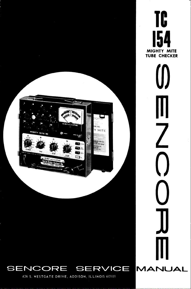
TC
1 5 4
MIGHTY MITE
TUBE CHECKE R
0
)
SENCORE SERVICE
426 S. WESTGATE DRIVE, ADDISON, ILLINOI S 60101
0
0
Ί)
M a n u a l .
Page 2
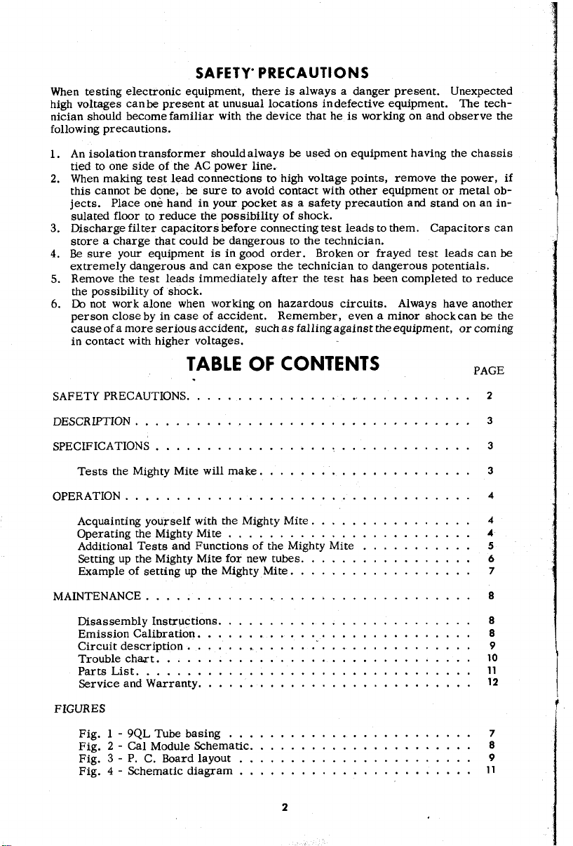
SAFETY’ P RECA UTION S
When test ing e lectronic equipme nt, there i s alw ays a danger present. Unexpect ed
high vo lta ges can be pres ent a t unusual lo cations in de fective equipment. The t ec h
nic i an should bec ome familiar with the device that he i s wo rking on and observe the
follow ing pre cautions.
1. An isolation transformer should always be used on equipment hav ing the chassis
tied to one sid e of the AC po wer l in e.
2. When ma king test lead connections to h igh vo ltage point s, remove the power, i f
this cann ot be d one, b e sur e to av oid contact with other equ i pment or metal ob
jects. Place o ne hand in yo ur poc ket as a safety pre cauti on and stand on an in
sulated floor to reduce the possibil ity of s hoc k.
3. Disc ha rge filter cap acit ors b efore connec ting tes t l eads to the m. Capacitors c an
stor e a charge that co uld be dangerous to the tec hnician.
4. Be su re your equipment is in good order. Broken or frayed test leads can be
ext re m el y d angerous and can e xpo se the t echnician to dangerous potentia ls.
5. Remov e the test leads i mmediately after the test has be en completed to reduce
the po ss ibil ity o f shock.
6. Do not work alone when w orki ng on hazardous circuits. A l ways have another
perso n close by in case of ac cident. Remem be r, even a minor shock ca n be the
cau se o f a m ore seri ous ac cident, suc h as falling against the equipment , or comin g
in contact with higher voltages.
TABLE OF CONTENTS PAGE
SAFETY PRECAUTIONS....................................................................................................
DESCRIPTION......................................................................................................................
SPECIFICA TIO NS
Tests the Mighty M i te will make
OPERATION..........................................................................................................................
Acqu aintin g yourself with the Mighty M ite
Operating the Mi ghty M ite .....................................................................................
Add i tional Tes ts and Func tions of the M i g h ty M i te
Setting up the Might y Mite for new tubes
Exa mple o f s etting up the Mi ghty M ite...............................................................
MAINTEN ANCE...................................................................................................................
Disassembl y In structi on s
Emissi on Calibrat ion................................................................................................
Circ uit d escript ion
Tr oub l e chaxt...............................................................................................................
Parts L ist......................................................................................................................
Ser vice and Warranty................................................................................................
FIGURES
Fi g. 1 - 9QL T ube bas i n g .....................................................................................
Fig . 2 - Cal Mod ule Schematic..............................................................................
Fi g. 3 - P. C. Board la y out
Fig. 4 - Schemati c d ia gram .................................................................................
...........................................................
......................
...........................................................
.................................
...................
...
.............................................................................
.................................................................................
...
...............................................
...................................................
.......................................................
.....................................
.......................................................
.....
.....
.....
.....
.....
.....
.....
.....
.....
.....
.....
.....
.....
.....
.....
.....
.....
.....
.....
.....
.....
2
3
3
3
4
4
4
5
6
7
8
8
8
9
10
11
12
7
8
9
11
2
Page 3

INSTR UCTIO N MANUAL FOR THE SENC ORE TC154
MIGHTY MITE VI TUBE TE STER.
DES CRIPTION
The new Senco re Might y Mite VI r eprese nts a unique brea kthrough in tube testers .
The M ighty Mite VI is compl etely solid state using the FET in a balanced b rid ge for
an i nstant on checker. This new outs tanding fe ature means that no time is wasted
wa i t ing f or the checker to warm up and stabil iz e before accurate testing c an begi n.
The new Migh ty Mite is ready as s oon as itis turnedon. A full load cat hod e cur rent
ch eck, high se nsitivi ty grid leakage check, and the famo us Se ncore Stethoscopi c
shorts test ma ke this the ideal check er for service work and the man o n the go.
Check the fe atures of the Mighty Mi t e below :
* Full load cathode current ch eck to pick out the weak tubes othe r checkers miss.
* 100 megohm grid leakag e sensitiv ity to find the tough dog tubes f ast.
* Steth osc opi c sh or ts test of 300K to pic k out true shorts in the tube.
* Burnout pro of meter , ev en if a shorted tube is tested backwa rds.
* FET bal anced bridge c ircui tr y for instant on action and greater accura cy .
* All steel c ase f or ma xim um pr otectio n and g ood looks for the life o f the checker.
SPECIFICATIO NS
Cathode Emission Test : Fu ll load curren t draw n throug h tube up to 120 mA . Max
applied voltage, 40 VAC RMS.
Grid Leakage Test: Good a rea, in finity to 200 megohm s, ? ar ea , 200 to 100 megohm s
and the Bad area 100 megohm s o r l e ss.
Shor ts Test: 300,000 oh ms or less will caus e s horts li ght to come on. Maxim um
applied voltage, 40 VAC RMS.
Power: 105 to 12 5 VAC, 50/ 60 Hertz at 32 watts maximum.
TESTS THE M I GHTY MITE WILL MAK E
Cathode Emission: The Mi g hty M i te tests all tubes at near their full ra ted cathode
curr ent level for the best emi ssion c heck. Th is is very import ant as many te ster s
do not test at this high lev el of cu rren t and c an pass many tubes as g ood that wil l not
work satisfactor ily in the ci rc uit. Thi s test is ver y important o n high power tubes
such a s rect if ier s, horizont al and sound output tubes.
Grid Le akage T est: Gr id lea kage or grid emi ssion in a tube can upset many c ircuits,
incl udin g the AGC, Chrom a, Video , Sy nc, ando th er s. Grid cur rents as low as one
microam pc an change the bias in th ese circui ts causing many headaches. TheM igh ty
Mite det ec ts grid cu rren t as low a s one-half a mic roamp or 1 00 megohms to pi ck out
these tr ouble making tu bes that ar e ofte n m issed by oth er tube checker s. As soon
as the tube is warm en o ugh to indicate ca thode emissi on, the gri d leaka ge test can
be pref ormed.
3
Page 4
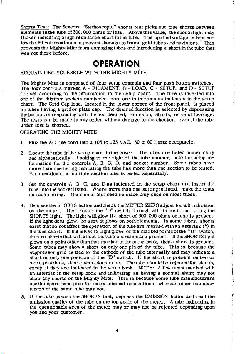
Shorts Test: T h e Sencore "S teth oscopic " shorts test pic ks out t rue sh orts betw een
el eme nt s in the tube of 300,000 oh ms or les s. Above this val ue, the sho rt s light may
flicker indicat ing a high re sis tance s ho rt in the tube. The a ppl ied v oltage is kept be
low the 50 volt maximum to pre ve nt damage to frame gri d tubes andnuv istors . Th is
prevents the Migh t y Mite from damaging tubes and introdu cing a sh or t in the tube that
was not there befor e.
OPERATION
ACQUAINTING YOURSELF WITH THE MIGHTY MITE
The Mighty Mite is compose d of four setup control s and four push button switc hes.
The four controls marked A - FILAME NT, B - LOAD, C - SETUP, and D - SETUP
are s et accor ding to the in for ma tion in the setup chart. The tube is inserted into
on e of the thi rte en soc kets num bered fr om on e to thirte en as ind ica ted in the setup
chart. Th e Grid Cap lead, located in the low er c or ne r of the fr ont panel, is pla ced
on tubes ha ving a gri d or pla te cap. The d esired function is selecte d by depres sing
the button corre sponding with t he test de sired , Emission, Short s, or Gr id Leakage.
The tests can be made in any orde r witho ut damag e to the che cker, even i f th e tube
under tes t is s horted.
OPERATING THE MIGHTY MITE
1. Plug the AC lin e c ord into a 105 to 125 VAC, 50 to 60 He rtz rec eptacle.
2. Locate the tube in the s etup chart in the cov er. The tub es are listed numerically
and alphab etical ly. L ookin g to the r ight of th e tube number, note the s etup in
formation for the cont ro ls A, B, C, D, and socket n umber. Some tubes have
more than one li sting indicating the tube has more than one section to be tested.
Each s ecti on of a m ult iple section tube is tes ted separ ately.
3. Set the controls A, B, C, and D as i ndicated in the se tup chart and inse rt the
tube in t o the socke t listed. W h ere more than one setti ng is listed, make the tests
on each setting . The shorts test need be mad e only once on most tubes.
4. Depress the SHORTS button and check the METER ZERO adj ust for aO indication
on the meter. Th en rotate the "D" swit ch through all its positi ons noting the
SHORTS light. The light will glow if a sh or t of 300,00 0 oh ms or less is present .
If th e ligh t does glow , be sur e it glows on both elem ents. In some tubes, short s
e xist that do not a ffect the operatio n of the tube are marked with an asterisk (*) in
the tube chart. If the SHORTS lightglows on the m arked points o f the "D" swi tch,
then no shorts that will affect the tube operation are present. If the SHORTS light
gl ows on a poin t other than that m arked in the setup book , then a short is presen t.
Some tubes may show a short on on ly one pin of the tube. Th is is because the
suppressor grid is tie d to the cathode of the tube in ternal ly and may indicate a
short on only one positio n of the ”D" s witch. If the short is p resent on two or
more po sitions, than a shortd oes e xist. The tube should be rej ec ted for sho rts,
except if they are indicated in the se tup book. NOTE: A few tubes marked with
an aster is k i n the setup book and ind ica ting a s havin g a nor ma l short m ay not
show any shorts on the M i ghty Mite. This is because some tube manu factu rers
use the s pa re base pins f or extra inter nal connect ions, whereas other man ufa c
turer s of the same tube may not.
5. If th e tube passes the SHORTS test, depress the EMISSION button and read the
em iss ion qua l ity o f the tube on the top scale of the meter . A tube indi cat ing in
the quest ionab le ar ea of the meter may or m ay not b e reject ed depe nding upon
you and your cus tomer .
4
Page 5

6. If the tube reads in the GOOD area of the met er and p a sses the EMISSION test,
depres s the GRID LEAKAGE butto n and read the grid leakage of the tube o n the
bottom scale of the m et er. This is a very important ch eck and will sh ow up a lot
of troublesome tubes that ma y ot herwi se c heck g ood. If th e mete r is indicating
in th e GOOD a rea of the meter but slowly ri sing, wait a m inute or so to see if
the meter will finally climb into th e BAD ar ea of the mete r. On he avy power
tub es, such as a hori zo ntal outpu t tube, do not make a g rid l eakage check a fter
an ex tended emission ch eck. If the tube is left in the emissi on chec k po sition
fo r several min utes, the gri d will heat up and when sw itched to grid leakage will
re ad hig her than normal. Al low the tube to cool slightly before ma king the grid
leakage check. You can expedite the grid leakage ch ec k by raising the filament
sw itch for a few se con ds. This is not the sa me overheating as was ca us ed in the
em ission che ck, but will show up g rid leaka ge . If the grid leakage indicati on
climbs into the BAD area on the meter, r educ e the filament voltage and see if
the meter remains in the bad ar ea. If it d oes so, then the tube will give trouble
in the cir cuit and should be re pl ac ed. If the met er dr ops off rapi dly back int o
the GOOD area, then the tube is good .
If the tube passes all the abo ve tests, it can be co nsidered good and should not be
replaced. If the tube is in the qu est ionable a re a on any te st, it is up to you or your
customer to deci de if the tube should be replaced. Show your customer the action
of the m eter indication on the tube and explain w h at will h appen. In this m ann er, the
Might y Mite becomes your customer convincer on new tube s ales.
ADDITIONAL TE STS AND FUNCTIONS OF THE MIGHTY MITE
Tube Life Expec tancy Tes’t: If the m et er needle climbs very slowly into the GOOD
area or Questio nable area o f the meter on the Emission test, the life exp ectancy of
the tube c an be conside re d much le ss than if the meter i ndicated GOOD in a sh or ter
pe rio d o f ti me. Al so, if the need le should climb into the GOOD ar ea and th en " f all
off", l ife expec tancy can be conside re d much less. We can not recomme nd that y ou
rep la ce these tub es. Tha t decision is up to you or your customer.
Fi lament Warm-Up Time: When replac ing a costly hori zontal output tube in a tele
visi on receiver , it i s a good idea to notonly c heck the horizo ntal os cilla tor for em is
sion and other standard tests , but to also check the leng t h of time it takes to warm up.
If the horizontal oscilla tor tube is slower in wa rming up than the ou tput tube, the
output tube will draw heav y cur rent and its life will be shortened considerably.
Checking the warm up time of the oscillator tube and making sure that it is as fast
or faster than the output tube can redu ce the ch ance of a call back later for the sa me
trouble and ke ep your cus tomer's conf idence h igh in yo ur servic e abili ty.
Filament V oltage Se nsitivity: Some tubes m ay c heck good o n the em iss ion test and
p ass the oth er test in the Mighty Mite, but may not always operate in the r eceiver.
These tubes may have a f ila men t sensitive c athode . That is, the emis si on from the
tube w ill change with a change in fi lament voltage. These tubes can give trouble,
especially in the newer series string receivers . A quick check on these tubes is to
re duce the Filament swit ch "A" down one step and obser ve the emiss ion reading on
the me ter of the Mighty Mite. A new tube will not change its em ission re adin g at all
when this step is preforme d. A tube havi ng a filament sensitive cathode w ill drop
in emi ssion read ing when the filamen t swi tch is reduced one step. If the tube falls
below the qu estion abl e ar ea, the tube will give trouble in the circui t and should b e
re placed . If your in the home, be sure to show your custo mer th e tube and how it
check s on the Mighty Mit e.
Rejuvenation: If you wis h to rejuvenate a sm all tube, mere ly increas e the filame nt
voltage by sett ing switch "A" one setti ng higher fo r ten to fifteen s ec onds. Th is wi ll
super heat the cat hode and b oil out mo re emitting material fr om under the o xid e
coatin g. Th is is onl y a tempora ry m easure as rejuvenation of a rec ei vin g tube will
not last very long.
5
Page 6

SETTI NG UP THE MIGHTY MITE FOR NEW TUBES
New tubes ca n so m etim es be a p roble m a s they may not b e listed in the se tup chart.
This can be the case, especial ly on new sets just int rod uced by the set manufac turer s.
With an u nder standing of the setup co nt rols on the Mi ghty Mite, you can set up and
ch eck a ny new tube that is not listed in the setup chart.
A FILAME NT Switch : This switch s elects the filamen t v oltage a ppl ied to th e tube
under test from 1 (one) to ove r 50 vol ts. The twelv e posit ion switch s elect s a r ang e
of vo ltage and with the un iqu e design of the filament trans former, the tube under t est
w ill load the transfo rmer to obtain the cor rect voltage for testing. When setting up
a new tube, simply set the A FILAMENT switch to the corre ct voltage or vo ltage
range.
B LOAD Sw it ch: This swit ch selec ts the proper AC vol tag e to be applied to the pla te
of the tube as wel l as the c orrec t load resistor so that the tu bes desi gn ed cu rren t
can b e set and the tube checked under f ull loa d. The current ra nges for the settings
of the B LOAD switch are a s follo ws:
B LOAD switch Cathode Cur r e nt B LOAD s w i tc h Ca t ho de Curre nt
A 50 m A plus F 2-7 mA
B 20-50 m A G ,7-2 m A
C 15-30 mA h . 5 -. 8 mA
D 10-1 6 mA j ,5 mA or less
E 6-12 mA
The current that the B LOAD switch is set to is the normal cathode current und e r
norma l bias co nditions as listed in the tube manual. If a tube ma nual is not handy,
then us ing Ohms law, compu te the cathode cur rent b y the voltage drop across the
cath ode or pla te load resistor in the circui t or from the sche matic.
C SETUP Switch : The C SETUP switch is used to isolate extra conn ectio ns inside
of the tube s uch as two gri d p ins so th at tests can be made. For ex amp le, Fig ur e 1
shows a typic al base diagram for a hori zo ntal outp u t tube, the 6JE6. Note that the
control grid is conne cted to pins 2 and 6 o n the tube base. Sin ce the control gr id
must be picked up for the t est, one of the connect ions must be isolated or ope ned up
so that the test can be made. The fol lowing sh ows the pins is olat ed with the setti ngs
of the "C" SETUP swi tch.
SETUP Switch
1
2
3
4
5
6
Pin isol ate d o n Tu b e ba s e
1 7
2
3
4 10
5
No pi ns iso lat ed , 12
a ll fee d thr o u gh
C SETUP Sw itc h
8
9 8
11
Pin isol ate d on Tube ba s e
6
7
9
10
No pins i solated,
a ll feed through
In the exam ple of Figu re 1, if pin 2 were chosen to b e is olat ed, the "C" swit ch would
be set to po sition 2. If you choose to isola te pin 6, then the "C" switch would be set
to 7 as indica t ed in the above ch ar t. If there are no extra co nn ections to be iso late d in
the tube, then the ”C” swi tch will be set to pos ition 6 so that all pins feed di rectly
through.
D SETUP Switch: The "D" swit ch is us ed to pick up the control gr id tor th e test
on the tu b e. I twas discovere d many years ago, that app roximatel y 97% of the elec
trons would go to the co nt ro l grid wh en chec king cath ode em ission so that t his is now
used as the pick-up element. In the exampl e of Figure 1, th e "D" swit ch would be
set to one of the c on tro l grids that is not isolated. If pin 2 were to be i solated, then
the "D” swi tch would be set to pickup pin 6. The following chart shows the positi ons
of the "D" switch and the tube pins that a re pi cke d up:
6
Page 7

D SWIT CH settings Pin on Tube ba se picked up D SWITCH settings Pin on Tube base picked up
A 1 G 7
B 2 H 8
C 3 J 9
D 4 K 10 and the grid ca p l ead
E 5 H-K Not used as a pick-up
F 6
The only ex ception to the abov e is o n s oc ket num ber 10 wher e pin 11 on the tube base
is picked up with
So ckets numb e r
the first position of the "D" sw itch.
TE R M I N AL CO N NE C T I O N S
Pin I - Gr id «2
Pin 2 - G rid #1
Pi n 3 - Co thod e
Pin 4 — H e ate r
Pin 5 - Heo ter
Pin 6 - Gri d #!
Pin 7 - G r id #2
BOTTOM VIEW
Figur e 1. 9QL Tube basin g
Pi n 8 - G rid *f3
Pin 9 - In te rn o l conn e ct io n
— do no t use
Cop - P l a te
3 and 8 are wir ed identical exc ept that so cket number 8 has thre e
pins not connected. Thi s socket is used to iso late ex tra connect ions wh ere more
than two ba se pins ar e connected to the same el ement such as i n the 1X2 hig h voltage
r ect if ier . The sev en pi n' sockets 4 and 7 are al ike ex ce pt that the fi lament pins on
socket 4 are 3 and 4 while on socket 7 the y a re 1 and 7.
SOCKET SETUP: The sockets on the Mighty Mi t e have th e fi lament pins prewir ed to
eliminate the extra setup that i s in volved. The a ctual p in connecti on s can be seen
on the schemati c diagram of the un it. Note that th e two octal sockets have different
filament connect ions. Sock et numbe r 1 i s for fi laments on pin s 2 an d 7 whil e so ck et
num ber 2 is for filaments on pins 7 and 8. Sockets 3, 8, and 13 are f or st andard 9
pin base tubes. Socke ts 3 and 8 have f ilament s o n pin s 4 and 5 while socket number
13 i s fo r special Hi-Fi tubes with f ilament s on pin s 1 and 2.
Ther e ar e two novar sockets that a re wired id en tical . Socket num ber 5 is for the
stan dard novar based tubes while socke t number 12 is for the magnoval based t ube s.
The pins on the magnoval base d tub es are larg er in d iameter than the st andard novar
base and can damage the novar socket. All ma gno val tubes are ch ecked in socket
numb e r 12 to prevent d ama ge to the regular novar s ocket num ber 5. When selec ting
the socke t for a new tube, se lect the socket for the filament wiring as well as the
socket the tube shoul d fi t int o.
EXAMPLE OF SE TTING UP THE MIGHTY MITE
L ets us e for our example, the6JE 6 shown in Figure 1. Thi s tube is a sta ndar d novar
base tube with the control grid tied to two pins on the tube base.
FIRST: Deter mine th e soc ket to use. In this case, th e tube is a standa rd novar base
tube so that socket numb er 5 will be used.
SECOND: Determine the filame nt vol tage. In this cas e, it is the 6JE6 so that the
filament sw itch "A" will be set to 6. The fir st set of numbers on the tube generally
indicate the filamen t v oltage o f the tube. On foreign tube s, consu lt a substitu tion
guide to find the filament voltage and cha racteri stics that can be used to ch eck the
tube.
THIRD: Select the current range that the tube is to be checked at using the infor
ma tion u n d er "SETTING UP THE MIGHTY MITE FOR NEW TUBES", the B LOAD
sw itch secti on. For our example , the A po sitio n wo u ld be us ed as the 6JE6 dra ws a
very heavy plat e curren t under norma l use.
7
Page 8

FOURTH: Se lect any pins that mu st be isola ted for a p rope r tes t. In this ex ample,
we have the control grid on pins 2 and 6 and the scre en gri d on pins 1 and 7 . The
"C" switch canisolate only one pin, s o we will isol ate the extra cont ro l grid connec
tion in the tube. The two scree n conn ectio ns will cause the short s light to gl ow and
th er efor e a nor mal shorts indication will exis t u n der the tube setting s. Isolate pin
2 by s etting the ”C" switch to position 2.
FIFTH: Select the cont ro l grid pin with the "D" SETUP sw itch. In this case, since
we isolat edpin 2, we mustpick uppin 6w hichis po si tionF onthe "D" switch. When
we rotat e the "D" s witch for the sho rts t es t, the short light will glow on pins 1 and
7 o r po sitions A and F of the switch and should be consid ered normal. Any ot her
indicatio n o n th is tube would indicate an interna l short.
MAINTENANCE
DISASSEMBLY INSTRUCTIONS
To r emo ve the Mighty Mite from i ts case for ad jus tment of the i nternal ca libration
co ntr ol or for any repa irs that may be necessary:
The front panel sho uld now be lifted fro m th e c ase, e xposin g the internal circuits of
the Mighty Mite for cal ibratio n or trouble shooting . To reassembl e the Mighty Mite,
simply revers e the procedure .
CALIBRATION
The Mighty Mite sh ould sel dom ch ang e i ts calib ra tion thro u gh it s normal li fe. With
the cal ibration module described below, you will not only be abl e to reca librate the
Mikity M i te, but per io di cally ch eck its calibration and insure yourself of top pre-
form ance. The m odul e is constru cted from an o ctal pl ug or an old octal tube base
and is i nserted into socket numbe r one on the Mig hty Mite. F igur e 2 show s the s che
m ati c o f the tes t modul e.
1. Remo ve the two screws a t the top o f the front panel.
2. Remove the two s crews on the b ack of the case near the
bott om of the unit .
CR1 = Silicon Diode, 100PIV @
R1 = 1 00 M e g (4-22 MEG and
1-12 MEG in series)
R2 = 270K
R3 = IK, 1%
Figu r e 2. Col Modu le Sch e mati c OLD TUB E BASE OR OCTAL PLUG
There are two calibrat ion control s on the pri nted circuit board in the Mi g h t y Mite.
See Figure 3 fo r t hei r location. The grid leakage must b e set first and the n the
em ission cont rol. The gr id le akage c on trol is in series with the meter and will affect
both emis sio n and gri d leakage cal ibration. Using the test module described above,
plu g it into socket number one and set the four fr ont panel controls with the foll owing
setting s. A B C D SKT
Grid Lea kag e C alibra tion 1 D 6 D 1
Depr ess the SHORTS b u tto n and set the mete r to zero with the METER ZERO c on trol.
Depr ess the GRID LEAKAGE button and ad jus t R ll, the Grid Le aka ge cal co ntrol
unti l the meter rea ds on the lin e between ? and BAD. D epress the SHORTS button
and re check the meter zero. To ch eck and ca libr at e the emissi on control, use the
fol lowing set tings: A B C D SKT
Emissi on Calibration 1 D 6 C 1
With the SHORTS button d epres sed, check the meter ze ro. Depr es s the EMISSION
BUTTON and adjust R17, the Emission Cal control until the meter rea ds AiTon the
em ission sc ale of the meter . £ &
5AMP
CRI Rll R 2 | R3 1
ί
8
Page 9

To check the sh or ts indi cat ing circuit of the Might y Mit e, depress the SHORTS button
and rotate the "D" switch through all its po sitions. Normal sh orts should occu r on
pos iti ons E and F.
CIRCUIT DESCRIPTION OF THE MIGHTY MITE VI
The new Mi ghty M ite VI represe nts a unique breakthrough in tube c hec kers, being
the first co mpl etely solid state tube checker. The new Mighty Mite uses the new
FET or Field Effec t transi stor in place of the usual tube givin g instanton a ction f or
faster and more acc urat e tube testing. Now, ther e is no need for the tube in the
tes ter to warm up and stabilize before chec king can begin and the ch ange in cali
bra tion that goes along with th e aging tube are als o gone with the new sol id state
Migh ty Mite.
The basic ci rcuit of the Mighty Mi t e is a bal anc ed bridge c ircuit meter ampii tier
consi sting o f F ETTR 1 anddiodeCR 4. The z ener diode r epresen ts a consta nt c ur rent
sou rce and takes the place' of the second FET nee ded for the bri dge circ uit. The
METER ZERO cont rol on the front panel is just like the z ero co ntrol of a VTVM and
balances the ci rcu it so with no sign al input, the meter rea ds zero. When a volta ge
is im presse d on the gate of the FET TR1, the br idg e is unba lance d and the meter
w ill read in propo rtio n to the a ppl ied s igna l.
The c atho de emissi on test puts an AC volta ge betwe en the c on trol g rid of the tube
under test and the cathode w ith a l oad resistor in series to deve lop a pulsatin g DC
voltage across. The B LOAD s witch selects the di ffere nt size load resist o r s and
applied vo l tag e so that a full range of cu rr ent is avail ab le from le ss than . 5 mA to
120 mA. The tube un der tes t rect ifies the app lied AC vo l tage and deve lops across
the l oad resi stors R1 throug h R7. The pulsat ing DC voltage is coupled through the
filt er netw ork of R17 and C6 to sm ooth i t to a pure DC voltage. Th is vo lta ge is ap
pl ied to the gate of TR1 through an additional isol ation and filterin g netw ork of R14 ,
R15, R20 andC3 . The resu ltant DC voltage ups ets the balance of the circuit causing
the meter to r ead upscale in proportio n to the emission q ualit y of the tube.
In the gri d leakage test , the control grid of the tube under test is ma de nega tive to
all other elemen ts in the tube by connect ing the grid to grou nd through the 30 m egohm
gat e resistor consisting of R 1 5 and R20, a n d applying a positive 8 volts t o all o ther
elements in the tube. If the tube ha s a ny g rid leakage or contaminat ion ca using the
tube gr id to emitt electron s, the flow of electro ns will be through the gate resistor.
Any current flow through the resistor will cause a v oltage dr op across the r esistor
causi ng an unba lance in the bridge circuit and the mete r to r ea d in proportion to the
amount of grid c ur rent in the tube under test. A leakage of 100 me gohms or less
will cause the meter to read into the BAD a rea . A leakage of 100 to 2 0 0 megohms
will cause a meter rea ding in the questiona ble a re a and a le akage of 200 megohm s
or m ore w ill read in the GOOD area on the meter . A leakage of 100 m egohms rep
rese nts a grid cu rrent in the tube u nder test of . 5 microam ps .
9
Page 10

The sh or ts test us es the Sencore Stethoscopic ap proach wher e each and ev ery el eme nt
in the tube is checked agai nst all othe r el ements. A c apacitor voltage divid er of Cl
andC4 is place d across the upper windin g of the primary of the filamen t tran sformer.
The AC voltage at this poi nt is 7 5 volts and the capa cit or Cl d rop s this to appro x
imatel y 34 volt s RMS that is applied acros s the elem ent s of th e tub e. This voltage
is below the ma ximum that sho uld be ap plied to nu vistors and frame grid tu bes to
pr event ar e ov er and bre a kdown in these tubes . C5, a . 1 condenser is in series with
the shorts t es t to prevent an y DC action of the tube fro m lighting the shorts lig ht. A
true short wi ll cause both e leme nts of the neon bulb to ligh t. If the short is 300, 000
oh ms or less, the short s light w ill glow, but if the sh or t is hig her in res istance, the
shorts light may o nly flicker.
The power sup ply fo r the FET and the le akage tests consis ts o f dio de CR1 and filter
cond enser C2. Th e necessary AC voltage is taken from the 22 volt tap on the p rimary
of the fil ament transf ormer T l . Zener diode CR2 and r esis tor R10 r eg ulate the
supply volt age to 8 volts so th at the voltage remai ns c onsta nt regar dless of the l ine
vol tage a pplied to the unit.
TROUBLE C HART FOR THE MIGHTY MITE VI
SYMPTOM
No meter indicati on on
any p osi tio n of push
button Funct i on switch.
Grid leakage meas ures
OK, but no emission
read ings.
Short ind ica t or glows on
one anode when c hecking
for shorts.
Bad tu bes indic ate ver y
good or full sca le.
Shorts light will not
glow, even with a
direc t s hort.
Emissi on OK, but Grid
leakage readin gs
not rig ht or absent.
PROBABLE CAUSE
CR1, CR2, T R 1, CR3
SI, T l, Grid leakage
push button contacts.
Shorted or leaky C5
Open lo ad resistor R1
to R7 or open contacts
on emissi on p ush button.
Open C5, op en con tacts
on SHORTS push button
sw itch.
Open c onta ct s on Grid
leakage push button
switch. Leakage CAL
off.
CORRECTIVE MEASURE
Ch eck d iodes and power
supply vo ltage . Check FET
with FET te ster and chec k
meter for open with ohm
meter.
Check resistors on B load
switch with oh m meter .
Check tran sformer for
opens and Grid leaka ge
switch for open contacts.
Check C5 for short ed or
leaky co ndit i on and
replace.
Check R1 to R7 for open s
with o hm m eter. Ch eck
contacts on pu s h sw i tch.
Check C5 for open and
replace . Chec k c ontacts
on switch.
Check conta cts on swit ch.
Ch eck and reset Lea kag e
CAL pot.
10
Page 11

MIGHTY MIT E VI PARTS LIST
SCHEMATIC NUMBER PART NO
R1
R ll
R12
R15
/CR1
CR2 50G8
CR3
CR4
TR1 19G35
Cl
>> C2
C4
SI
S2
S3
S4
S5
Tl
#11
#12
λ, Λ
(PRICES SUBJECT TO CHANGE WITHOUT NOTICE)
14G129
15G61
15S6
14G334
1651 0
19G16
50G10
24G81
>2 4G206
24G179
25S42A 2P9P R otary S w itch
25S22A
25S41A
25S43B
25B130
28B10
26G54
26G56
23B34
36G2 Grid Cap and Lead
SC8B20
DESCRIPTION
300 OHM 10W Taped
Re sist or
5K 30% PC Vert Mt
CAL POT
200 OHM 30% Carb o n
Co ntro l
30 MEG 1/2W 10% Re sist or
400 VPIV 5 AMP Silicon
Diod e
8. 2 V 1 Watt Zener Diode 1.95
IN816 Sta bistor Diode .7 5
2. 2V 20 m A Zener Dio de 1.9 5
2N54 57 F ET (S elect ed )
.00 62 MFG 5% bUUV
50 M FD 35 V Lyti c .7 5
. 0056 MFD 33 V Poly .25
1P12P Rotary Switch
11P12P Rotary Switch
2P11P Rotary Sw itch
2P4 Section P ush Button
Filament Transformer
10 Pin Sp eci al Soc ket
9 Pin Ma gnoval
0- 1 MA M eter 20.00
Contro l Esc utc heon
C ase Compl ete
PRICE
$ .95
.75
1 .50
.25
1 .50
1 .25
.25
3 .25
2.00
5.95
3.25
4.95
9.95
.50
.50
Page 12

Ca se Com p le te
(PRICES SUBJECT TO CHANGE WITHOUT NOTICE)
TCI54 SCHEMATIC , ,
 Loading...