

Page 1

SDI2X
SDI / IP Gateway Platform
User Manual
March 2019
8089R www.sencore.com | 1.605.978.4600 Revision 1.20
Page 2

SDI2X – User Manual
Date
Version
Description
Author
1/25/2018
0.1
First Draft
TDH
09/24/2018
0.2
Document format change
TDH
09/25/2018
1.0
Initial Release
TDH
3/14/2019
1.1
Corrected typo and added Default IP values
TDH
Copyright
© 2018 Sencore, Inc. All rights reserved.
3200 Sencore Drive, Sioux Falls, SD USA
www.sencore.com
This publication contains confidential, proprietary, and trade secret information. No part of this document
may be copied, photocopied, reproduced, translated, or reduced to any machine-readable or electronic
format without prior written permission from Sencore. Information in this document is subject to change
without notice and Sencore Inc. assumes no responsibility or liability for any errors or inaccuracies.
Sencore, Sencore Inc, and the Sencore logo are trademarks or registered trademarks in the United States
and other countries. All other products or services mentioned in this document are identified by the
trademarks, service marks, or product names as designated by the companies who market those products.
Inquiries should be made directly to those companies. This document may also have links to third-party web
pages that are beyond the control of Sencore. The presence of such links does not imply that Sencore
endorses or recommends the content on those pages. Sencore acknowledges the use of third-party open
source software and licenses in some Sencore products. This freely available source code can be obtained
by contacting Sencore Inc.
About Sencore
Sencore is an engineering leader in the development of high-quality signal transmission solutions for the
broadcast, cable, satellite, IPTV, telecommunications, and professional audio/video markets. The
company’s world-class portfolio includes video delivery products, system monitoring and analysis solutions,
and test and measurement equipment, all designed to support system interoperability and backed by bestin-class customer support. Sencore meets the rapidly changing needs of modern media by ensuring the
efficient delivery of high-quality video from the source to the home. For more information, visit
www.sencore.com.
Revision History
Page 2 (48)
Page 3

SDI2X – User Manual
Safety Instructions
Read these instructions
Keep these instructions
Heed all warnings
Follow all instructions
Do not use this apparatus near water
Clean only with dry cloth
Do not block any ventilation openings. Install in accordance with the
manufacturer’s instructions
Do not install near any heat sources such as radiators, heat registers, stoves, or
other apparatus (including amplifiers) that produce heat
Do not defeat the safety purpose of the polarized or grounding-type plug. A
polarized plug has two blades with one wider than the other. A grounding type
plug has two blades and a third grounding prong. The wide blade or the third
prong is provided for your safety. If the provided plug does not fit into your outlet,
consult an electrician for replacement of the obsolete outlet.
Protect the power cord from being walked on or pinched particularly at plugs,
convenience receptacles, and the point where they exit from the apparatus.
Only use attachments/accessories specified by the manufacturer.
Unplug this apparatus during lightning storms or when unused for long periods of
time.
Refer all servicing to qualified service personnel. Servicing is required when the
apparatus has been damaged in any way, such as power-supply cord or plug is
damaged, liquid has been spilled or objects have fallen into the apparatus, the
apparatus has been exposed to rain or moisture, does not operate normally, or
has been dropped.
Do not expose this apparatus to dripping or splashing and ensure that no objects
filled with liquids, such as vases, are placed on the apparatus.
To completely disconnect this apparatus from the AC Mains, disconnect the
power supply cord plug from the AC receptacle.
The mains plug of the power supply cord shall remain readily operable.
Damage Requiring Service: Unplug this product from the wall outlet and refer
servicing to qualified service personnel under the following conditions:
o When the power-supply cord or plug is damaged.
o If liquid has been spilled, or objects have fallen into the product.
o If the product has been exposed to rain or water.
o If the product does not operate normally by following the operating
instructions. Adjust only those controls that are covered by the
operating instructions as an improper adjustment of the controls may
result in damage and will often require extensive work by a qualified
technician to restore the product to its normal operation.
o If the product has been dropped or damaged in any way.
o The product exhibits a distinct change in performance.
Replacement Parts: When replacement parts are required, be sure the service
technician uses replacement parts specified by Sencore, or parts having the
same operating characteristics as the original parts. Unauthorized part
substitutions made may result in fire, electric shock or other hazards.
Page 3 (48)
Page 4

SDI2X – User Manual
SAFETY PRECAUTIONS
There is always a danger present when using electronic equipment.
Every precaution has been taken in the design of your product to ensure that it is as safe
as possible. However, safe operation depends on you the operator.
Always be sure your equipment is in good working order. Ensure that all points of
connection are secure to the chassis and that protective covers are in place and
secured with fasteners.
Never work alone when working in hazardous conditions. Always have another
person close by in case of an accident.
Always refer to the manual for safe operation. If you have a question about the
application or operation email ProCare@Sencore.com
WARNING – To reduce the risk of fire or electrical shock never allow your
equipment to be exposed to water, rain or high moisture environments. If
exposed to a liquid, remove power safely (at the breaker) and send your
equipment to be serviced by a qualified technician.
To reduce the risk of shock the power supply must be connected to a mains
socket outlet with a protective earth ground connection.
For the mains plug the main disconnect and should remain readily accessible
and operable at all times.
When utilizing DC power supply, the power supply MUST be used in conjunction
with an over-current protective device rated at 50 V, 5 A, type: Slow-blo, as part
of battery-supply circuit.
To reduce the risk of shock and damage to equipment, it is recommended to
ground the unit to the installation’s rack, the vehicle’s chassis, the battery’s
negative terminal, and/or earth ground. Warning: Changes or modifications to
this unit not expressly approved by the party responsible for compliance could
void the user’s authority to operate the equipment.
Package Contents
The following is a list of the items that are included in the shipping carton:
1. SDI2X
2. AC Power Cable
If either of these items were omitted from the packaging please email ProCare@Sencore.com to obtain a
replacement.
Page 4 (48)
Page 5

SDI2X – User Manual
Table of Contents
Section 1 Overview ............................................................................................. 7
1.1 Product Introduction ..................................................................................................... 8
1.2 Front Panel Overview .................................................................................................. 8
1.3 Rear Panel Overview ................................................................................................... 9
1.4 Cooling ......................................................................................................................... 9
1.5 Rack Information .......................................................................................................... 9
Section 2 Installation ........................................................................................ 10
2.1 Installation .................................................................................................................. 11
2.2 AC Power Connection ............................................................................................... 11
2.3 Maintenance .............................................................................................................. 11
2.4 Management Network Setup via Front Panel ............................................................ 11
Section 3 Operating the Front Panel ............................................................... 13
3.1 SDI2X Front Panel Overview ..................................................................................... 14
Section 4 Operating the Web Interface ........................................................... 15
4.1 SDI2X Web Interface Overview ................................................................................. 16
4.1.1 Logging into the SDI2X Web Interface ................................................................. 16
4.1.2 Control Panels ...................................................................................................... 16
4.1.3 Title ribbons .......................................................................................................... 16
4.1.4 Buttons and Status Indicators............................................................................... 17
Section 5 Web Interface Control Panels ......................................................... 18
5.1 SMPTE Control Panel ................................................................................................ 19
5.1.1 HDMI Monitoring Output ....................................................................................... 19
5.1.2 Channel Configuration .......................................................................................... 20
5.1.3 Configuring the Video/IP ports (SDI IP) ........................................................... 20
5.1.4 Configuring the Video/IP ports (IP SDI) ........................................................... 21
5.2 Admin Control Panel .................................................................................................. 25
5.2.1 Changing Unit Password ...................................................................................... 25
5.2.2 Profiles .................................................................................................................. 25
5.2.3 SNMP MIB files .................................................................................................... 26
5.2.4 Diagnostics ........................................................................................................... 27
5.2.5 Updating the SDI2X software ............................................................................... 28
5.2.6 Reboot the unit .................................................................................................... 29
5.2.7 Reset to Defaults ................................................................................................. 30
5.2.8 UID Indicator ......................................................................................................... 30
5.2.9 Unit Alias............................................................................................................... 31
5.2.10 Configuring the Network Ports ............................................................................. 31
5.2.11 Configuring SNMP ................................................................................................ 35
5.2.12 Syslog ................................................................................................................... 36
5.3 Reporting Panel ......................................................................................................... 36
5.3.1 Alarms ................................................................................................................... 37
5.3.2 Configuring the Alarms ......................................................................................... 37
5.3.3 Event Logs ............................................................................................................ 39
5.3.4 Configuring the Logs ............................................................................................ 40
5.4 About Control Panel ................................................................................................... 40
5.4.1 System Information ............................................................................................... 40
5.4.2 Contact Information .............................................................................................. 40
5.4.3 Hardware .............................................................................................................. 41
5.4.4 Third Party Software Information .......................................................................... 41
5.4.5 System Recovery ................................................................................................. 41
Section 6 Appendices ....................................................................................... 42
Appendix A – Error and Event List ........................................................... 43
Page 5 (48)
Page 6

SDI2X – User Manual
Appendix B – Acronyms and Glossary .................................................... 44
Appendix C – Specifications ..................................................................... 45
Appendix D – Warranty ............................................................................. 46
Appendix E – Support and Contact Information ..................................... 46
Appendix F – Open Source Software ....................................................... 47
Page 6 (48)
Page 7

SDI2X – User Manual
Section 1 Overview
Introduction
This section includes the following topics:
1.1 Product Introduction ..................................................................................................... 8
1.2 Front Panel Overview .................................................................................................. 8
1.3 Rear Panel Overview ................................................................................................... 9
1.4 Cooling ......................................................................................................................... 9
1.5 Rack Information .......................................................................................................... 9
Page 7 (48)
Page 8

SDI2X – User Manual
2
1
3 4 5
1.1 Product Introduction
The new SDI2X is a simple solution to bridge the gap between traditional SDI and IP
infrastructure.
The SDI2X maintains the long standing Sencore tradition of coupling ease of use, with a
straight-forward web interface to give the user complete control of the unit and signals
being processed.
The SDI2X supports both SDI to IP and IP to SDI workflows, and with its powerful
processor, chosen with future standards in mind, the SDI2X will be a convenient tool for
years to come.
Designed flexibly to support SMPTE 2022-6 and TR-03/SMPTE 2110. The SDI2X is a
must have for those considering baseband A/V over IP deployments.
The SDI2X platform supports one or more channels which can be configured to convert
SDI video inputs into IP output streams, or IP input streams into SDI video outputs. The
user can configure the direction (SDI->IP or IP->SDI) for each channel independently.
The platform will encapsulate or de-encapsulate the SDI video according to SMPTE
2022-6 standard.
The platform also supports redundancy using SMPTE 2022-7 seamless switching
standard.
1.2 Front Panel Overview
The SDI2X front panel will provide the user with
1. Input and Error LED’s for fast indication of unit, and stream processing status
2. A brightly lit LCD display provides details of configuration and signal processing
3. Up, Down, Left, Right arrow buttons for menu navigation using the front panel
4. Back, OK buttons for menu navigation and selection entry using the front panel
5. Unit Identification LED – for fast indication of specific unit within a system
Page 8 (48)
Page 9

SDI2X – User Manual
1
2
3
456
1.3 Rear Panel Overview
The SDI2X back panel will provide the user with the following connections
1. 120 VAC power outlet
2. Unit Identification LED – for fast indication of specific unit within a system
3. Copper RJ45 network port “1 CONTROL”
4. Four (4) Bi-directional 3G SDI BNC connectors “3G SDI I/O 1-4”
5. HDMI 2.0 monitoring port allows viewing of received IP video streams
6. Two (2) SFP Gigabit Ethernet Ports “1/10 GBE 2” and 1/10 GBE 3”
Sencore offers three (3) optional SFP adaptors that will allow the user the following
port configurations
10G Fiber (Sencore part SDI2X-10G-SFP-FIBER)
1G Fiber (Sencore part SDI2X-1G-SFP-FIBER)
1G RJ45 Copper (Sencore part SDI2X-RJ45-COPPER)
1.4 Cooling
The SSDI2X is cooled via forced induction through the front of the unit and
exhausted through the vents in the rear. The unit is equipped with a internal
temperature sensor. If the internal temperature exceeds 60°C the “Error” LED will
illuminate on the front panel and an error message will appear in the “Error List.”
1.5 Rack Information
The SDI2X is versatile and was designed to be deoployed as a ‘throw down’ device
for easy installation into locations with limited space. Or, with the optional rack mount
kit, the user can deploy three (3) SDI2X in a standard 19” rack and occupy slightly
more than 1RU of rack space.
Page 9 (48)
Page 10

SDI2X – User Manual
Section 2 Installation
Introduction
This section includes the following topics:
2.1 Installation .................................................................................................................. 11
2.3 AC Power Connection ............................................................................................... 11
2.6 Maintenance .............................................................................................................. 11
2.7 Network Setup via Front Panel .................................................................................. 11
Page 10 (48)
Page 11
SDI2X – User Manual
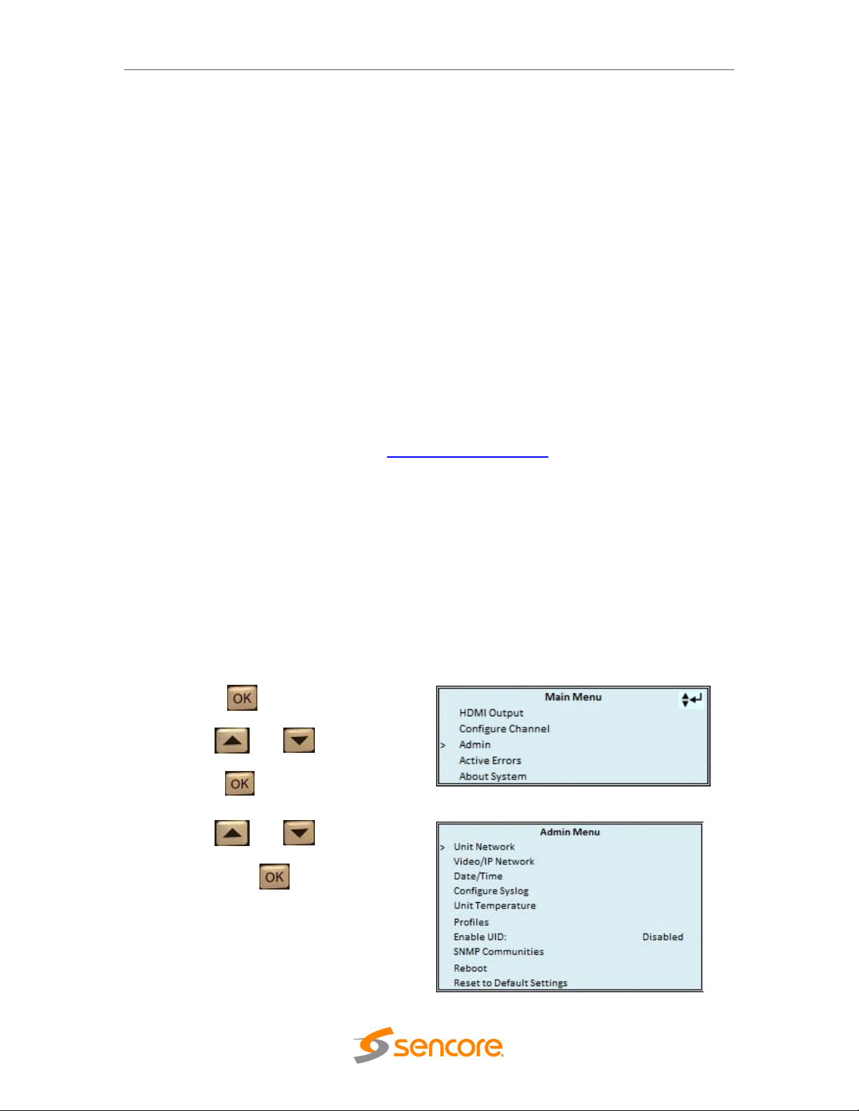
1. Press the button.
2. Use the and buttons to
move the cursor to “Admin”, then
press the button.
3. Use the and buttons to
move the cursor to “Unit Network”,
then press the button.
2.1 Installation
The SDI2X is small enough to be deployed as a standalone device, or placed into a rack
system using the optional rack mount (Sencore part number 7C1489) hardware which
will allow up to three (3) SDI2X to occupy a space slightly more than 1 rack unit.
2.2 AC Power Connection
The SDI2X is powered by a single connection to a 120V 60Hz source.To hook up the
power use the following steps:
1. Locate the AC power cord that was included.
2. Plug the female end (end with no prongs) of power cord into the back of the unit.
3. Locate a protected outlet to plug the male end of the power cable into.
2.3 Maintenance
The SDI2X is a maintenance-free piece of equipment. There are no user serviceable
parts on the inside of the unit. To request a copy of the latest SDI2X software or release
notes from Sencore, send an email to ProCare@sencore.com .
2.4 Management Network Setup via Front Panel
By default the management IP address will be static, and use the following settings
Address = 10.0.0.61; Subnet Mask = 255.255.255.0; Default Gateway = 0.0.0.0
The SDI2X can be setup on a network connection to allow remote management and
SNMP configuration. For these features to work, the network settings for the SDI2X must
first be configured properly for the network it is connected to.
Static IP Address
To setup the SDI2X with a static IP address, use the following steps:
Page 11 (48)
Page 12
SDI2X – User Manual
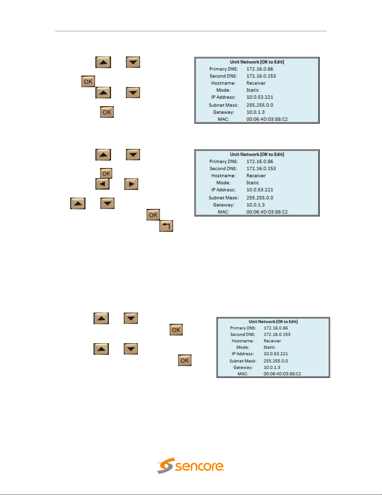
4. Use the and buttons to
move the cursor to “Mode”, then press
the button.
5. Use the and buttons to
change the selection to “Static” then
press the button.
1. Use the and buttons to
move the cursor to “IP Address”, then
press the button.
2. Use the and buttons to
select the column to edit and use the
and buttons to change the
location value. Press the button
to save the selection and the
button to return to setting selection.
3. Repeat steps 1 and 2 for “Subnet
Mask” and “Gateway” configuration
settings.
1. Use the and buttons to move the
cursor to “Mode:” then press the button.
2. Use the and buttons to change the
selection to “DHCP” then press the
button to save the selection.
IP Address/Subnet Mask/Gateway
DHCP
The SDI2X can be configured to use DHCP to obtain an IP address/Subnet
Mask/Gateway.
Note: It may take up to a minute for the SDI2Xto obtain an IP address. During this
time the unit will display a “busy” message next to DHCP.
Page 12 (48)
Page 13

Section 3 Operating the Front
Introduction
SDI2X – User Manual
Panel
This section includes the following topics:
3.1 SDI2X Front Panel Overview ..................................................................................... 14
Page 13 (48)
Page 14
SDI2X – User Manual
1
4
2
3
1
3
2
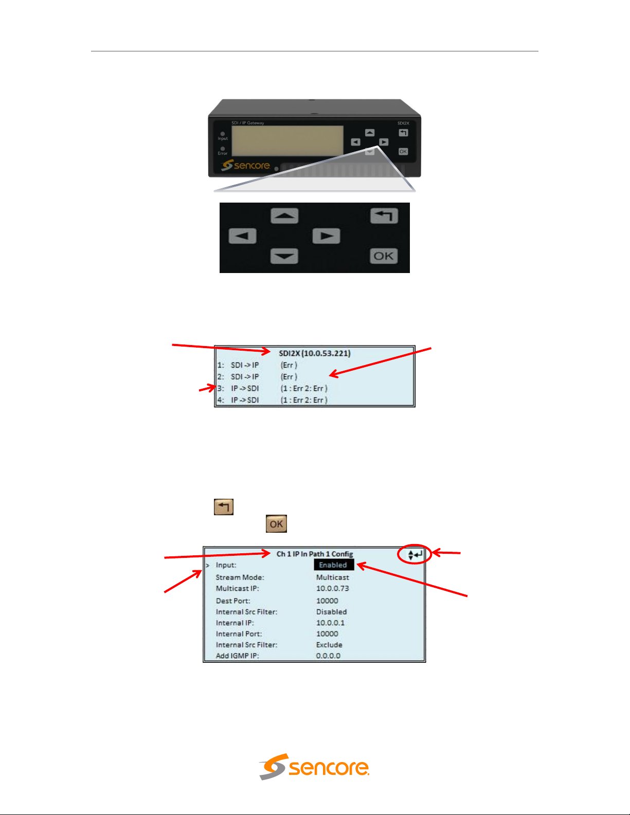
3.1 SDI2X Front Panel Overview
The SDI2X front panel allows the user to configure all settings that are present in the
web interface using the buttons located on the front of the unit. The screen below is the
idle screen of the SDI2X and provides the user with the following details at a glance
1. IP address of management port
2. Current path configuration of each available channel.
3. Stream processing condition of each path.
When viewing the menu screens, it is important to observe some of the important
features that have been noted below. They are common to all screens and provide
helpful information. The button allows the user to return to the home screen, cancel
settings and go back a menu. The button is used to select and save selections.
1. Screen title.
2. Icons indicate which control buttons are currently valid for entry.
3. Cursor shows which line is active.
4. When editing, active character or item is highlighted.
Page 14 (48)
Page 15

Section 4 Operating the Web
Introduction
SDI2X – User Manual
Interface
This section includes the following topics:
4.1 SDI2X Web Interface Overview ................................................................................. 16
4.1.1 Logging Into the SDI2X web interface ....................................................................... 16
4.1.2 Control Panels ........................................................................................................... 16
4.1.3 Title Ribbons .............................................................................................................. 16
4.1.4 Buttons and Status Indicators .................................................................................... 17
Page 15 (48)
Page 16

SDI2X – User Manual
SMPTE
This control panel is where the majority of the video stream
processing configuration and monitoring settings are located.
Admin
This control panel is where unit hardware and administrative settings
will get configured and monitored.
Reporting
This control panel is where alarms & logs are reported, configured
and maintained.
About
This control panel is where unit software and hardware details are
found.
4.1 SDI2X Web Interface Overview
4.1.1 Logging into the SDI2X Web Interface
To open the SDI2X web interface use one of the following supported browsers and
navigate to the unit’s IP address:
Internet Explorer 9 & above
Mozilla Firefox
Google Chrome, or
Microsoft Edge
The user will need to login to the web interface. By default the admin user account is
available without a password. Press the login button in order to login to the web
interface.
4.1.2 Control Panels
The web interface will provide complete control of unit configuration and process
monitoring with four (4) separately defined control panels. Each control panel will be
made up of unit features that are similar to each other to help the user easily locate the
unit features they seek. The control panels are:
4.1.3 Title ribbons
The Admin and About control panels will have similar feature specific settings grouped
together under a title ribbon. The title ribbon will have an icon and general description of
the settings that are offered beneath the ribbon. The title ribbons can be expanded or
collapsed using the control button at the right end of the ribbon.
Page 16 (48)
Page 17

SDI2X – User Manual
Green LED
Status is good. No errors are present and function is operating
normally.
Red LED
Status indicates function is affected by active error. To view the
errors navigate to Alarms panel to view Active Errors.
Grey LED
Status is inactive. Function is currently disabled or unavailable.
4.1.4 Buttons and Status Indicators
When the icon is shown user configuration is available. Clicking this button will open
menus where settings can be changed by the user.
When the icon is shown additional status information can be viewed. Click this button
will expand the menu to display the additional status information. All text in status menus
shown in ORANGE are user configurable settings. Text shown in BLUE report status
and details about the stream being processed. Clicking the collapse icon will close
the details viewing window.
Status in the SDI2X web interface is shown with LED status indicators:
Page 17 (48)
Page 18

SDI2X – User Manual
Section 5 Web Interface Control
Panels
Introduction
This section includes the following topics:
5.1 SMPTE Control Panel ................................................................................................ 19
5.2 Admin Panel .............................................................................................................. 25
5.3 Reporting Panel ......................................................................................................... 36
5.4 About Panel ............................................................................................................... 40
Page 18 (48)
Page 19

SDI2X – User Manual
5.1 SMPTE Control Panel
The SMPTE control panel of the SDI2x web interface is used to configure the video
processing details. This will include signal flow direction, configuring the Video/IP ports,
labeling of the channel and finally, channel monitoring.
The SDI2X offers redundancy that meets the SMPTE 2022-7 seamless switching
standard requirements. This setting is found on the Admin Control Panel and has a unit
wide coverage. This means that the setting is applied to all stream processing paths.
Default value for this option is ‘Seamless’.
When the SDI2X operates in ‘Seamless’ mode, all IP port configuration menus will
provide two paths (a primary path and a redundant path) to configure. When the SDI2X
operates with this value at ‘Disabled’, all IP port configuration menus will allow the user
to assign the output path to a specific hardware video IP port (see section 3.3.6.1 on
page XX for more details.). In the next section, examples of both configuration windows
will be addressed.
The SDI2X offers four (4) channels that the user can configure for video processing.
Each channel will offer the same configuration settings but operate independently from
the other channels.
5.1.1 HDMI Monitoring Output
The SDI2X provides the user with an HDMI output port (V2.0b) on the back of the unit
that will allow the user to monitor the IP input video stream. This output is able to be
assigned to the IP source port of any channels that is configured as IP SDI.
Configuration and status for this feature is found near the top of the SMPTE control
panel.
Page 19 (48)
Page 20

SDI2X – User Manual
HDMI Output
Possible settings are Enabled and Disabled.
Source
Possible settings are Channel 1, Channel 2,
Channel 3, and Channel 4.
Only available if channel direction is IP
SDI.
Alias
The user can assign a defining name or title to the
stream processing path. This label is only available to
the SDI2X interfaces; it will not be incorporated into the
video stream data.
Direction
Possible settings are SDI IP and IP SDI. This
setting represents the video processing path direction. It
will always be shown as (Input) (Output).
5.1.2 Channel Configuration
Click the configuration cog below the channel title ribbon to open the configuration
window. The user has two settings to control, Alias and Direction.
5.1.3 Configuring the Video/IP ports (SDI IP)
When the signal processing direction is SDI IP, the IP ports will be configured as
outputs.
Seamless Redundancy Enabled
When redundancy is enabled, the SDI2X will provide a primary IP output stream path on
one of the gigabit network ports, and a redundant IP output stream path on the other
gigabit network port. The output stream on both ports will contain the same content to
meet the seamless switching standard (SMPTE 2022-7). Configurable settings will be
the same for both paths/ports.
Begin by clicking on the “IP Output” configure cog icon. The IP Output Confirugation
window will have a tab for Path 1 and a tab for Path 2. There are three available settings
to configure for each path.
Page 20 (48)
Page 21

SDI2X – User Manual
Output
Possible settings are Enable and
Disable
Destination IP
Address
Assign a four decimal octet number as
Destination address. Address will be in
form of XXX.XXX.XXX.XXX.
Destination
Port
Assign the Destination port number.
Connector
Possible settings are 1/10 GbE Port 2,
and 1/10 GbE Port 3. This will define
the physical port the stream will be
available on.
Output
Possible settings are Enable and
Disable.
Destination IP
address
Assign a four decimal octet number as
Destination address. The address will
be in the form of XXX.XXX.XXX.XXX
Destination Port
Assign the Destination port number.
Seamless Redundancy Disabled
When redundancy is disabled, the SDI2X will only provide a primary IP output stream
path to configure.
The user will need to define which of the gigabit network ports the output will be
available on and then configure that port.
Click on the “IP Output” configure cog icon.
5.1.4 Configuring the Video/IP ports (IP SDI)
When the signal processing direction is IP SDI, the IP ports will be configured as
Inputs.
Page 21 (48)
Page 22

SDI2X – User Manual
Video Format
Mode
Possible settings are Auto
and Manual.
Auto
The SDI2X will
automatically detect the
input video format.
Manual
The user will select an
input video format
Manual Video
Format
This drop down box is
only available when the
video format mode is set
to Manual. It provides the
user with a list of 25 predefined video formats to
choose from.
Note
Auto mode should always be used when the input video format is unknown. The SDI2X
will report an error if the input video format does not match the manual setting
De-jitter/De-skew
Buffer
This setting will control the amount of buffering done to the input
stream. Possible settings are Disabled, Low, Medium and High.
Disabled
No buffering will be done, latency is negligible.
Low Tolerance
(10ms)
Minimal buffering is done. Latency is <= 10ms.
Medium Tolerance
(50ms)
Average buffering is done. Latency is <= 50ms.
High Tolerance
(150ms)
Maximum buffering is done. Latency is <= 150ms.
Seamless Redundancy Enabled
When redundancy is enabled, the SDI2X will provide a primary IP input stream path on
one of the gigabit network ports, and a redundant IP input stream path on the other
gigabit network port. The input stream on both ports must contain the same content to
meet the seamless switching standard (SMPTE 2022-7).
Click on the “IP Input” congfiguration cog to opent he IP Input Configuration window.
Configuration settings within the top pane will apply to both stream processing paths and
are considered ‘global’ because all processing paths receive these settings. Settings in
the lower pane are applied to the processing path defined by the selected tab.
Global stream processing settings
Page 22 (48)
Page 23

SDI2X – User Manual
Input
Possible settings are Enabled
and Disabled.
Stream Mode
Possible settings are Multicast
and Unicast.
Destination IP
address
Assign a four decimal octet
number as Destination address.
The address will be in the form
of XXX.XXX.XXX.XXX
Destination
Port
Assign the Destination port
number
Internal
Source Filter
Possible settings are Enabled
and Disabled.
Internal
Source Filter
IP
Assign a four decimal octet
number as the Internal Source
Filter IP address.
Internal
Source Filter
Port
Assign the Internal Source
Filter port number
IGMP Filter
Mode
Possible settings are Include
and Exclude. Defines filter
management of IGMP
Addresses in list window at
bottom of window.
IGMP Filter
Address list
User entered IGMP addresses
are displayed and managed
(added, removed) within this
section of the configuration
window.
Path specific stream processing settings
Seamless Redundancy disabled
When redundancy is disabled, the SDI2X will only provide a primary IP input stream path
to configure, and the user will need to define which of the gigabit network ports the
stream will be received on. Click on the “IP Input” configure cog icon.
Some path configuration settings will be the same whether seamless redundancy is
enabled or disabled and the extended description for these will be left out of the table
below.
Page 23 (48)
Page 24

SDI2X – User Manual
Video Format Mode
Possible settings are Auto and Manual.
Manual Video
Format
User selects from drop down list of 25 pre-defined formats.
Note: Use auto mode if input format is unknown to prevent format mismatch error.
De-jitter/De-skew
Buffer
User selects from these settings: Disabled, Low, Medium and
High.
Connector
Possible settings are 1/10
GbE Port 2 and 1/10 GbE
Port 3.
Input
Possible settings are Enable
and Disable.
Stream
Mode
Possible settings are
Multicast and Unicast.
Destination
IP address
Assign a four decimal octet
number as Destination
address. The address will be
in the form of
XXX.XXX.XXX.XXX
Destination
Port
Assign the Destination port
number
Internal
Source
Filter
Enable/Disable the tab
defined internal source filter.
Internal
Source
Filter IP
Assign a four decimal octet
number as the Internal
Source Filter IP address.
Internal
Source
Filter Port
Assign the Internal Source
Filter port number
IGMP Filter
Mode
Possible settings are Include
and Exclude. Defines filter
management of IGMP
Addresses in list window at
bottom of window.
IGMP Filter
Address
list
User entered IGMP
addresses are displayed and
managed (added, removed)
within this section of the
configuration window.
Page 24 (48)
Page 25

SDI2X – User Manual
The configuration button for this feature will be
found under the Admin Control Panel title ribbon.
This feature provides the SDI2X user management
control of the web interface access password.
In order to make changes to passwords, click the
change password button.
A window will appear to enter the current password
and new password. Click “Apply” to save and exit.
5.2 Admin Control Panel
To access the Admin Control Panel, click on the Admin tab. This page will offer the user
to control many global settings and maintenance tasks on the SDI2X.
5.2.1 Changing Unit Password
5.2.2 Profiles
The SDI2X has the ability to save all configured settings to multiple profiles. Profiles can
be saved locally, renamed and saved to external storage to be used on other SDI2X.
Profiles can be used to quickly and easily change the configuration of an SDI2X to suit
different inputs and decoding requirements.
Page 25 (48)
Page 26

Add New Profile
Adds a new profile from current settings. User must
name profile before creation is complete.
Upload Profile
Allows the user to browse to external storage or
workstation to upload profile to SDI2X.
Apply Profile
Select a profile from the drop down menu and click
this button. The SDI2X will apply all settings
contained in the profile selected.
Rename Profile
Select a profile from the drop down menu and click
this button. The user will be prompted for a new
name for the profile.
Delete Profile
Select a profile from the drop down menu and click
this button. The user will be prompted to confirm
deletion of the profile.
Download Profile
Select a profile from the drop down menu and click
this button. The user will be prompted to select a
directory to download the profile.
5.2.3 SNMP MIB files
SDI2X – User Manual
The SNMP MIB files for the SDI2X can be obtained by clicking on the SNMP MIBs
button at the top of the page.
This will open a new tab within the current web browser and give the user a list of all
available MIB files.
Directions on how to save them to an external storage location are provided at the
bottom of the list.
Page 26 (48)
Page 27

SDI2X – User Manual
This window is replaced with a download file
window when file creation is complete.
The user will be asked to ‘Open’ or ‘Save’ the file.
Selecting the Save option will download the .XML
file to the pc ‘downloads’ location.
The file can then be opened with a number of
different software applications.
An example of the diagnostic file is shown below
5.2.4 Diagnostics
The SDI2X provides the user the ability to take a snapshot of the ALL current unit
settings, reported values, active alarms, and the alarm and log file history. This snapshot
will be downloaded as an .XML format file that can be attached in an email or opened for
viewing.
Click the ‘Diagnostics’ button and a window will open showing the diagnostic file creation
progress.
Page 27 (48)
Page 28

SDI2X – User Manual
Upload Software
Update
To upload software updates to the SDI2X click this
button. The user will be prompted to navigate to an
update file. The file will then upload to the SDI2X.
When complete the SDI2X with prompt the user to
either apply the update or cancel
Delete the Uploaded
Software
Clicking this button prompts the user to confirm the
deletion of the software update from the SDI2X.
This will also clear the Uploaded Version status of
the Software Versions section.
Update Software to
Uploaded Version
Clicking the button starts the software update
process. The SDI2X will prompt the user to confirm
the update. Click Yes to continue or No to cancel.
5.2.5 Updating the SDI2X software
Updates to the SDI2X are performed through the web interface. A software update file is
provided by Sencore and then uploaded to the unit. To request the latest software
version or a copy of the release notes please send an email to ProCare@Sencore.com
The ‘Update Unit’ button is in the top right corner of the Admin control panel. When
opened this feature will allow the user to advance the software version the SDI2X
operates on, or rollback the software version that the SDI2X operates on.
Applying software updates
Click on the “Update Unit” button to open the upload window.
Click on the “Upload” button to open a browse window. Navigate to the software file
location and double click on the update file.
A progress bar will give details on the file upload to the SDI2X.
The user will be asked to confirm the software update is to be performed.
Another progress bar will give details on the update installation.
The SDI2X will reboot after a software update is complete.
Page 28 (48)
Page 29

SDI2X – User Manual
Rollback Software
Clicking this button starts the Rollback process.
The SDI2X will prompt the user to confirm the
rollback or click cancel to stop the process.
The SDI2X can be rebooted from the web interface
Admin page. The ‘Reboot’ button is located in the
top right corner of the Admin Control Panel.
To perform a reboot, the user will click the reboot
button.
The system will prompt the user to confirm the
reboot request.
If confirmed, a status window with a progress bar
will open be visible until the reboot is complete and
the login window displayed.
Rollback software updates
The SDI2X is capable of reverting back to a previous version of software using the
Rollback feature. This is accomplished by maintaining two separate software images
within memory. One version will be the version that the system is presently operating on.
The second version will be the software version that the unit was previously settings.
A rollback will begin by opening the Update Unit window and then select the Rollback
tab.
The previous version of installed software will be shown along with a ‘Rollback’ and a
‘Cancel’ button.
5.2.6 Reboot the unit
Page 29 (48)
Page 30

SDI2X – User Manual
Yes
Confirm and execute the reset to default
settings action. The unit will reboot following
this selection.
No
Deny the request and close the Reset to
Defaults request window.
5.2.7 Reset to Defaults
The SDI2X offers the user the ability to reset to unit configuration to factory defaults.
All settings will be returned to the factory defaults except the network management ports
TCP/IP settings.
All event logs will also be cleared so be sure to save any logged data prior to resetting
the unit.
The SDI2X will prompt the user to confirm the action.
5.2.8 UID Indicator
With the small size of the SDI2X, and the ability to deploy up to four of these in a single
RU space it would be nice to have a feature that would allow a single unit, in a densely
populated system, be easily identified. The answer to this is the UID indicator. The
SDI2X has a blue LED located on the front and rear panels that can be controlled
through the web interface to provide easy detection of the units’ location.
Page 30 (48)
Page 31

SDI2X – User Manual
5.2.9 Unit Alias
The configuration button for this feature is found under the General Settings title ribbon
of the Admin control panel.
The Unit Alias is a unique name or description the user can assign to the SDI2X. The
‘Alias’ will be available on the unit web client and front panel.
When selected, the user will be provided a text entry box to enter the alias. The user will
then click the Apply button to save the changes made. The web client and front panel
will update immediately.
5.2.10 Configuring the Network Ports
Since the SDI2X has a defined management port that is independent of the video stream
processing ports, there are two network configuration sections on the Admin control
panel.
Configuring the Management Port
By default the management IP address will be static, and use the following settings
Address = 10.0.0.61; Subnet Mask = 255.255.255.0; Default Gateway = 0.0.0.0
The “Unit Network” title ribbon will address the management port (1 Control) settings and
configuration cog icons.
There are two configuration points for the management port; Configure Nameservers in
the upper row, and the hardware configuration cog icon on the lower row.
Page 31 (48)
Page 32

SDI2X – User Manual
Primary
Nameserver
a four decimal octet number in
form of XXX.XXX.XXX.XXX
Secondary
Nameserver
a four decimal octet number in
form of XXX.XXX.XXX.XXX
Mode
Possible settings are DHCP and Static.
DHCP
The SDI2X will have its’ IP address, Subnet
mask, and Gateway assigned by the network
server.
Static
The user must define IP address, Subnet
mask and Gateway of the SDI2X.
Hostname
The hostname is the user defined name that
can be used to reach the unit in place of the
IP address.
IP
Address
Four decimal octets in the form of
XXX.XXX.XXX.XXX
Subnet
Mask
Four decimal octets in the form of
XXX.XXX.XXX.XXX
Gateway
Four decimal octets in the form of
XXX.XXX.XXX.XXX
Configure Nameservers:
These addresses define the Primary and Secondary Domain Name Server(s) that are to
be used for Hostname resolution. The Hostname is assigned in the hardware
configuration window.
Hardware configuration:
When the hardware configuration cog is selected, the configuration window that opens
will provide the user with five settings. These are used to define the unit’s network
management port IP Address, Mode and Hostname.
Page 32 (48)
Page 33

SDI2X – User Manual
Configure Card settings (global)
ICMP Response
Possible settings are Enabled and Disabled.
ICMP - known as ‘Ping response’, is commonly used to test network connection path to
a known IP address. This feature can be enabled or disabled for the SFP ports.
Redundancy Mode
Possible settings are Seamless and Disabled.
Seamless
When seamless is selected, the SDI2X will operate within the
SMPTE 2022-6 standard mode. This mode will provide primary
and redundant paths for configuration in the separate stream
processing paths.
Disabled
When disabled the SDI2X will provide a single IP path for input
and output streams and the user will determine the appropriate
Port 2:
(Port specific settings) These settings will only apply to Port 2.
IP Address
Four decimal octets in form of XXX.XXX.XXX.XXX.
Subnet Mask
Four decimal octets in form of XXX.XXX.XXX.XXX.
Gateway
Four decimal octets in form of XXX.XXX.XXX.XXX.
Port 3:
(Port specific settings) These settings will only apply to Port 3.
IP Address
Four decimal octets in form of XXX.XXX.XXX.XXX.
Subnet Mask
Four decimal octets in form of XXX.XXX.XXX.XXX.
Gateway
Four decimal octets in form of XXX.XXX.XXX.XXX.
Configuring the Video/IP Ports
By default the management IP address will be static, and use the following settings
Port 2 Address = 10.0.0.62; Subnet Mask = 255.255.255.0; Gateway = 0.0.0.0
Port 3 Address = 10.0.0.63; Subnet Mask = 255.255.255.0; Gateway = 0.0.0.0
The “Video/IP Network” title ribbon addresses the port settings and configuration cog
icons for the two SFP Gigabit Ethernet Ports.
There are three configuration cogs available to the user.
The settings within the ‘Configure Card’ feature are referred to as ‘global’ settings. This
means that the settings here will be applied to both SFP ports.
Page 33 (48)
Page 34

The SDI2X can be set to synchronize with an NTP
server or a manual data and time can be defined by
the user.
Click the “Configure Date/Time” cog icon to begin.
These values are used to timestamp entries in the
Alarm and Event logs under the Reporting tab.
Update
Mode
NTP
Manual
Setting to NTP uses the local network’s NTP
server to synchronize date and time. Manual
allows the user to define a date and time.
NTP Server
Four decimal octets:
XXX.XXX.XXX.XXX
Domain Name
This is the IP Address or Domain Name of the
local NTP Server on the network. This setting
is only available if Update Mode is set to NTP.
Date
MM/DD/YYYY
This setting is the user defined date. A
calendar widget can be used to select the data
by clicking the button. This setting is only
available if Update Mode is set to Manual.
Time
00:00:00 – 24:00:00
This setting is the user defined time. The time
is based on a 24 hour clock. This setting is
only available if the Update Mode is set to
Manual.
Date/Time
SDI2X – User Manual
Page 34 (48)
Page 35

SDI2X – User Manual
Add Manager
Clicking this button prompts the user for the IP
address of the SNMP trap manager.
Delete All
Clicking this button prompts the user to confirm the
deletion of all SNMP trap manager IP addresses. If
the user confirms deletion all SNMP trap manager
IP addresses will be removed.
Delete Single Entry
Highlight a single SNMP trap manager IP address
and click this button to delete the entry. A prompt
will appear confirming the deletion of IP address.
5.2.11 Configuring SNMP
SNMP Communities
SNMP Communities define whether users have read-only or read-write SNMP rights.
These two communities are given unique names. The default names for these
communities are:
Read –Only Community: public
Read- Write Community: private
To modify the names of these communities click on the “Configure SNMP Communies”
cog icon.
SNMP Trap Managers
The SNMP trap managers are recipients of SNMP traps sent from the SDI2X. The
following menu allows the user to configure the recipient’s IP addresses. To add and
remove recipients of the SNMP traps click the Configure SNMP Trap Manager cog icon.
Page 35 (48)
Page 36

SDI2X – User Manual
State
Enabled
Disabled
Enable or Disable sending
messages to Syslog server.
Network
Protocol
UDP
TCP
Select which network
protocol used to transmit to
the Syslog server
IP
Address
Four decimal octets:
XXX.XXX.XXX.XXX
IP of the Syslog server.
0.0.0.0 and
255.255.255.255 are not
permitted
Port
0 - 65535
Destination port of the
Syslog server
5.2.12 Syslog
The SDI2X can be configured to send error and event logs formatted in the syslog
protocol to a remote user specified Syslog server.
5.3 Reporting Panel
The Reporting control panel in the SDI2X will provide the user with a list of active
alarms, as well as a means to log the detected events. Active alarms are constantly
updated to reflect the real-time state of the unit.
Once an error is no longer detected, it will be cleared from the active alarms window.
The log files can be used to view alarm and event history. Both the active alarm and
event logs can be configured for specific behavior based upon the user’s needs.
Page 36 (48)
Page 37

SDI2X – User Manual
State
This column displays an icon that will signify the importance of the
event
The icon means the message is Informational and no error has
been detected.
The icon means the message is an Alarm and the unit status has
been set to ‘Error’.
Name
This column displays the description of the detected instance.
Location
This column displays the hardware or function that is experiencing the
active error.
Last
Changed
This column displays the data and time the error was raised.
Timestamps here are determined with the Date and Time settings
configured in Section 4.2.11.
5.3.1 Alarms
Clicking on the Alarms button displays the Active Alarms menu. This list displays all of
the active alarms currently being reported by the unit. There are four columns in the log
that display different types of information.
5.3.2 Configuring the Alarms
The SDI2X monitoring points are divided into Conditions and Events. Configuration of
how the SDI2X responds to either of these can be done by clicking on the configuration
cog in either the Alarms or Logs windows.
Conditions
These instances are monitored within specific hardware and stream processing paths.
How the SDI2X responds to the detection of the instance can be configured here. There
are six columns in the Conditions tab. Three are ‘checkbox’ columns. Clicking the
checkbox at the top of the column can be used to enable or disable all instances in
column in a single action.
Page 37 (48)
Page 38

SDI2X – User Manual
Name
This shows the user the error message that will be provided if the instance is detected.
Location
This shows the user the specific hardware or stream processing path where the instance
is detected.
Log
The checkboxes allow the user to define which instances will be recorded to the log file.
Severity
A dropdown box within the row allows the user to define the instance as an Error or
Information.
Alarm
The checkboxes allow the user to define which instances will signal an Alarm condition on
the unit. This will cause the Error LED on the front of the unit and in the web client to
illuminate.
SNMP Trap
The checkboxes allow the user to define which instances will trigger the SDI2X to send
trap messages.
Apply
This will save all setting changes made and close the Configure Conditions and Events
window.
Cancel
This will cancel the request to edit and close the Configure Conditions and Events
window.
Name
This shows the user the error message that will be provided if the
instance is detected.
Location
This shows the user the specific hardware or stream processing path
where the instance is detected.
Log
The checkboxes are used user to define which instances will be
recorded to the log file.
SNMP Trap
The checkboxes are used to define which instances will trigger the
SDI2X to send trap messages.
Apply
This will save all setting changes made and close the Configure
Conditions and Events window.
Cancel
This will cancel the request to edit and close the Configure Conditions
and Events window.
Events
These instances will have an impact on all hardware and stream processing areas of the
SDI2X. These instances can only be configured to be recorded in the log file, and send
SNMP Trap messages. There are four columns in the Events tab.
Page 38 (48)
Page 39

SDI2X – User Manual
Refresh
This button allows the user to prompt the SDI2X to update
the web page displayed logs.
Clear
The log files can be cleared manually by clicking the Clear
button.
Download
The Download button lets the user save the log as a “.csv”
extension file on their pc.
Severity
This displays an icon that will signify the importance of the instance.
The icon means the message is Informational and no error has
been detected.
The icon means the message is an Alarm and the unit status
has been set to ‘Error’.
Timestamp
This is the SDI2X associated date and time of the instance. See
Date/Time settings in Section 4.2.11.
Transition
This displays an icon to indicate the type of log entry being shown.
The icon means that the instance transitioned into an Error
state.
The icon means that the instance transitioned into a Clear
state.
The icon means a single point instance (such as NTP Time
was updated) took place.
Location
This column displays the hardware or function that experienced the
alarm or event.
Message
This displays the description of the specific path that experienced the
instance.
5.3.3 Event Logs
The Logs window provides the user a display of the log file and management tools to
streamline the data returned. If the SDI2X is rebooted or power lost, the Log files are
cleared. There are three buttons that will manage the log file.
Page 39 (48)
Page 40

SDI2X – User Manual
5.3.4 Configuring the Logs
Configuration of the logs will provide the user with the same configuration options as
covered in section 4.3.11.
5.4 About Control Panel
Under the About control panel, there are no user definable parameters but there is
information about software versions currently installed, hardware within the unit, how to
contact Sencore for questions or assistance, and third party software information.
5.4.1 System Information
This area of the control panel gives the user the unit serial number and software version
installed.
5.4.2 Contact Information
This area of the control panel gives the user the physical address, web address and
phone number as methods of contact.
Page 40 (48)
Page 41

SDI2X – User Manual
5.4.3 Hardware
This area of the control panel will provide details about the hardware contents of the
SDI2X.
5.4.4 Third Party Software Information
This area of the control panel can be expanded to show the third party software used by
the SDI2x. For more details see Section 5 – Appendix D for a complete list.
5.4.5 System Recovery
The SDI2X system has the ability to recover from complete image corruption. The
system recovery allows a user to start the platform into a prompt where a software
update will allow the system to be installed in the event all other images will not work.
To use the system recovery, hold two front panel buttons (any 2 buttons) when power is
applied to the unit for at least 10 seconds.
The unit will boot into recovery mode. The user can press the “Enter” button on the front
panel to configure the IP address if necessary. A web browser can then be used to
connect to the system and apply an update to the unit.
Page 41 (48)
Page 42

SDI2X – User Manual
Section 6 Appendices
Introduction
This section includes the following appendices:
Appendix A – Error and Event List ........................................................... 43
Appendix B – Acronyms and Glossary .................................................... 44
Appendix C – Specifications ..................................................................... 45
Appendix D – Warranty ............................................................................. 46
Appendix E – Support and Contact Information ..................................... 46
Appendix F – Open Source Software ....................................................... 47
Page 42 (48)
Page 43

SDI2X – User Manual
Event Notification Defaults
Condition
Log Severity
Log Entry
Alarms
SNMP Trap
Unit Booted Event
Info**
Enabled
(n/a)
Disabled**
Unit Shutdown Event
Info**
Enabled
(n/a)
Disabled**
Update Succeeded Event
Info**
Enabled
(n/a)
Disabled**
Update Failed Event
Error**
Enabled
(n/a)
Disabled**
NTP Updated Event
Info
Enabled
(n/a)
Disabled
Date/Time Changed Event
Info
Enabled
(n/a)
Disabled
**Note: these events can be viewed in the Reporting tab of the Web Interface. These events will
not trigger SNMP traps or relays.
System Condition Notification Defaults
Condition
Log Severity
Log Entry
Alarms
SNMP Trap
Fan Failure
Error
Enabled
Enabled
Disabled
Temperature Out-of-Range
Error
Enabled
Enabled
Disabled
Link Loss
Error
Enabled
Enabled
Disabled
Port Transmit Overflow
Error
Enabled
Enabled
Disabled
Output TS Overflow Error
Error
Enabled
Enabled
Disabled
Video Bitrate Out of Range Error
Error
Enabled
Enabled
Disabled
SDI Input Lost Error
Error
Enabled
Enabled
Disabled
Alarm Objects
Alarm message
Alarm Sent By
HDMI Output Source Invalid
HDMI Output
IP Input Channel RTP Packets Missing
IP Input Channel W
IP Input Stream Loss
IP Input Channel W Path XX
IP Output Stream Unicast Receiver Not Found
IP Output Channel W Path XX
Network Connector Link Loss
Video/IP Network Connector YYY
Network Connector Transmit Overflow
Video/IP Network Connector YYY
SDI Input Lock Loss Error
SDI port ZZZZ
Temperature Error
Unit
Appendix A – Error and Event List
Below are the default settings for Event and System Condition notifications for the
SDI2X.
Below is a table of Alarm objects that are configurable by the user. See section 4.3.1.1
for configuration details.
W = Channel number (range 1 - 4). XX = IP Port number (range 1 – 2).
YYY = IP Port number (range 1 – 2). ZZZZ = SDI port number (range 1 - 4).
Page 43 (48)
Page 44

SDI2X – User Manual
Acronym
Interpreted from
AAC
Advanced Audio Coding
AC-3
Also known as Dolby Digital
AES
Audio Engineering Society
ATSC
Advanced Television Systems Committee
Bit Rate
The rate at which the compressed bit stream is delivered from the
channel to the input of a decoder.
BNC
British Naval Connector
dB
Decibel
DHCP
Dynamic Host Configuration Protocol
DVB
Digital Video Broadcasting
Event
An event is defined as a collection of elementary streams with a
common time base, an associated start time, and an associated end
time.
FCC
Federal Communications Commission
HD
High Definition
I/O
Input/Output
IP
Internet Protocol
Kbps
1000 bit per second
LED
Light Emitting Diode
Mbps
1,000,000 bits per second.
MPEG
Refers to standards developed by the ISO/IEC JTC1/SC29 WG11,
Moving Picture Experts Group. MPEG may also refer to the Group.
MPEG-2
Refers to ISO/IEC standards 13818-1 (Systems), 13818-2 (Video),
13818-3 (Audio), 1318-4
NTP
Networking Time Protocol
PCM
Pulse-Code Modulation
PID
Packet Identifier. A unique integer value used to associate elementary
streams of a program in a single or multi-program transport stream.
Program specific
information (PSI)
PSI consists of normative data which is necessary for the mapping of
transport streams and the successful regeneration of programs.
Program
A program is a collection of program elements. Program elements
may be elementary streams. Program elements need not have any
defined time base; those that do have a common time base and are
intended for synchronized presentation.
RU
Rack Unit
SD
Standard Definition
SDI
Serial Digital Interface
SI
System Information
SMPTE
Society of Motion Pictures and Television Engineers
SNMP
Simple Network Management Protocol
TS
Transport Stream
Appendix B – Acronyms and Glossary
Page 44 (48)
Page 45

SDI2X – User Manual
Input / Output Interfaces
Video Connections
1 x 3G-SDI BNC
1 x HDMI 2.0 Interface
Additional 3 x 3G-SDI BNC Optional *
Ethernet Connections
2x SFP+ Sockets (Data)
Supported SFP’s
1 GbE Fiber (MSA-Compliant)
1 GbE Copper (MSA-Compliant
10 GbE Fiber (MSA-Compliant)
Network Management connection
1x RJ-45 1GbE (Control)
Processing
Standards
SMPTE 2022-6 Encapsulate/De-encapsulate
SMPTE 2110 / VSF TR-03 *
Capacity
1x FHD/HD/SD Video Service
8x PCM Audio Pairs
Full ANC Data (SMPTE 2038)
Capacity (per 1 RU shelf)
3x 4k UHD/FHD/HD/SD Video Service *
Synchronization
SMPTE 2059 (IEEE 1588 PTP) *
Correction
Hitless Switching (SMPTE 2022-7) FEC (SMPTE 2022-5)
Management
Control Interfaces
Front Panel Interface (Four Line Display/Six-Button Keypad)
Web Interface
HTTP RESTful API
SNMP Status/Control/Traps Syslog Alarm Support
Form Factor
Dimensions
5.7”/145mm W x 6.7”/170mm D x 1RU
Rack Mount
3 Units per 1RU Tray
Environment
Power Standard
120 VAC / 240 VAC
Power Connector
Standard IEC Line Cord
Power over Ethernet *
Operating Temperature
0 to 50 Degrees Celcius
Appendix C – Specifications
* - Planned Roadmap
Page 45 (48)
Page 46

SDI2X – User Manual
Appendix D – Warranty
Sencore One-Year Warranty:
Sencore warrants this instrument against defects from any cause, except acts of God
and abusive use, for a period of 1 (one) year from date of purchase. During this warranty
period, Sencore will correct any covered defects without charge for parts, labor, or
recalibration.
Appendix E – Support and Contact Information
Returning Products for Service or Calibration
The SDI2X server is a delicate piece of equipment and needs to be serviced and
repaired by Sencore. Periodically it is necessary to return a product for repair or
calibration. In order to expedite this process please carefully read the instructions below.
RMA Number
Before any product can be returned for service or calibration, an RMA number must be
obtained. In order to obtain a RMA number, use the following steps.
1. Copy and paste, or enter the following link into a web browser:
a. http://www.sencore.com/procare-support/service-repair
2. Complete the on-line request form and click the Submit button at the bottom of
the page
3. Once the RMA is generated it will be emailed to the address provided on the
request. Shipping instructions will also be included.
Shipping the Product
Once an RMA number has been issued, the unit needs to be packaged and shipped
back to Sencore. It’s best to use the original box and packaging for the product but if this
not available, check with the customer service representative for the proper packaging
instructions.
Note: DO NOT return any power cables or accessories unless instructed to do so by the
customer service representative.
Page 46 (48)
Page 47

SDI2X – User Manual
Package
Version
License
Copyright
AT32 UC3B
Software
1.7.0
BSD
2009, Atmel Corporation
BusyBox
1.20.1
GPL Version 2, June 1991
Erik Anderson, et. al.
dfu-programmer
0.5.2
GPL Version 2, June 1991
Weston Schmidt
Dropbear
2016.74
MIT-like 2002-2015
Matt Johnston, et. al (see license)
E2fsprogs
1.41.9
GPL Version 2, June 1991
Theodore Ts’o
ethtool
2.6.34
GPL Version 2, June 1991
David Miller, et. al.
FamFamFam
Silk Icons
13
Creative Commons Attribution
2.5
Mark James
FastDB
3.71
MIT-like
Konstantin Knizhnik
FCGI
2.4.6
FastCGI
Open Market, Inc
Iproute2
3.4.0
GPL Version 2 June 1991
Stephen Hemminger, Alexey Kuznetsov
Libusb
0.1.12
GPL Version 2.1 Feb 1999
Johannes Erdfelt, Thomas Sailer, Brad Hards
Lighttpd
1.4.30
BSD 2004
Jan Kneschke
Linux
2.6.30
GPL Version 2 June 1991
Linus Torvalds, et. Al.
Log4cpp
1
GPL Version 2.1 Feb 1999
Bastiann Bakker
Monit
5.1.1
GPL Version 3 29 June 07
2010
Tildeslash Ltd.
Net-SNMP
5.7.1
BSD 1989, 1991, 1992
by Carnegie Mellon Univsty.
NTP
4.2.4p7
NTP License 1992-2009
David L. Mills
OpenEmbedded
2011.03
MIT 2006-2009
Holger Hans Peter Freyther, et. al
OpenSSL
1.0.1c
BSD-Like 1998-2008
The OpenSSL Project, 1995-1998
OProfile
0.9.7
GPL Version 2, June 1991
John Levon, Philippe Elie, et. al
PCRE
8.3
BSD 1997-2012
University of Cambridge, et. Al
POPT
1.14
MIT 1998
Red Hat Software
qDecoder
12.0.2
BSD 200-2012
Seungyoung Kim
Socket-CAN
1171
BSD-like, June 1991 20022007
Volkswagen Group Electronic Research
Spawn-FCGI
1.6.3
BSD
Jan Kneschke, Stefan Bahler
TCLAP
1.2.0
MIT 2003
Michael E Smoot
U-Boot
2009.11.1
GPL Version 2 June 1991
Wolfgane Denk, et. al.
USB-Utils
0.86
GPL Version 2 June 1991
Thomas Sailer, Johannes Erdfelt, David
Brownell,
Zlib
1.2.7
Zlib/libpng License 1995-2005
Jean-loup Gailly and Mark Adler
Appendix F – Open Source Software
The SDI2X includes:
Page 47 (48)
Page 48

Sencore Inc.
3200 Sencore Drive
Sioux Falls, SD 57107 USA
www.sencore.com
Copyright © 2018Sencore Inc. 1.605.978.4600
 Loading...