

Page 1
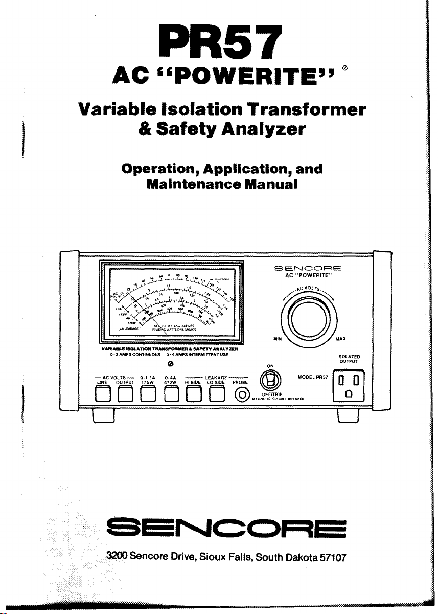
PR 5 7
AC “PO WER ITE ” *
Variable Isolation Transformer
& Safety Analyzer
Operation, Application, and
Maintenance Manual
S E N O O B E
AC “ P O W ERITE”
VAMABUE ISO LATION T RAN SFORMER A SA FETY ANALYZER
0 -3 AMPS CONTIN UO US 3 - 4 AMPS INTERMITTENT USE
LINE OUT P UT 17 S W 470 W HI SIDE LO SlOE
□ □ □ □ □ □
tzt
SENCORE
3200 Senc o re Drive , Sioux Falls , S o u th D a kota 5 7107
0 D
□
t T
Page 2
-------- ---------------
WARNING
------------------------
Please Observe Thes e Safety Precautio ns
Th ere is alw a ys a danger p resent wh e n te sti ng elec t ronic equip
m e nt. Unex p ecte d high voltages can be pres ent at unusua l
lo c a t ions in d efect i v e equ i pme nt. B e c o m e f ami l i ar with t he equ i p
m ent you’re w o r k i n g with and o b serve t he fo l lo wing sa fety pre
ca u t i ons.
Every p r ecau t i on has be e n t aken in t he de sign of y our i nstrument to
insure tha t i t is as safe a s p o s s i b le. H o wever , saf e o peration depe nds
on you, t he o p e r a t o r .
1. Ne v er excee d the limits o f this in str ument as giv e n in t he spe c i f i c a
tio n s ec t io n a n d th e ad diti ona l s p ec i a l war nings in t his ma n ual.
2. N e v e r u se t he PR57 to isola t e yo ur test eq uip ment, o n l y use it t o
isol a te t he eq uip men t that y o u are s e r v i c i n g .
3. N e v e r p l ug mo r e th an one unit at a time into th e PR57. To do so
could defeat t he isolat i o n t ransf ormer and p resent a p ossible sho c k
hazard t o the t e c hnici a n.
4. Remove t h e circu it powe r befor e making conne ct io n s t o hi g h vo lt a g e
poi n ts .
5. D i s c h a r g e f ilter capa citors be f o r e conn ecting test l e a d s to th e m.
6. Be sur e you r e qui pm ent is in go o d o rder. Bro ken o r f r a yed te st l e ad s
can be extremel y da n ge r ou s an d can expose you to dange ro u s voltages.
7. R e m o ve t he te st l e ads i mm e diat ely aft er t he test has be e n com
pl e t ed to reduce the poss i bili t y of shock.
8. Do not wo r k a lone w h e n w o r king on hazar dous c i r c uits. Always
ha v e an oth er pe r s on clo s e b y in cas e of an a c c i dent . Reme mber , e v en
a mi n o r sh ock ca n be the c aus e of a mo re seri o us ac c i dent , su ch as
fall in g ag ain st the equ i pm e nt, or c oming in contact w i th hig h
vol t a g e s .
9. Impr ope r Fuse(s ) Vo id Wa rranty. Fuses ar e for y our pr o t ection, so
alw ays re p l a c e f u s e wi th p r ope r t yp e and current ra t ing. The p r oper
fuse typ e d escript i on i s mar ked near t he fus e holde r and in the
instruc t ion man u al. Alway s :
a. Hav e the proper size re pla cement f u s e in s t o ck. W i t h each new
instrume nt, be su r e to up date y our fus e i nve nto r y w i t h an y
spec ia l v a l u e fus e s your ins t ru ment m ay req u i r e .
b. Av o i d s i tuati ons tha t will blow the f u s e . Whe n a p r otectio n f u se
blows, n ote what cau sed the fus e fai lu re . P reven t futu r e fus e
fai l u r e s b y follo w in g p r oper mea sur i ng procedure s .
Page 3
PR57
AC “ PO WER ITE”
Variable Isolation Transformer
& Safety Analyzer
Operation, Application, and
Maintenance Manual
VCQ». «*
SENCORE
...the electronic instrument “analyzer people"
3200 SE NC ORE DRIVE, SIOUX FA LL S . SOUTH DAKOTA 57107 -(605 )3 3 9 -0100
1
Page 4
TA B LE OF CONTENTS
SIMPLIFIED OPERATION
To Read V ol ta ge of AC Line or Isotated O u t p u t
To R ead W a t ta g e or C u rr ent ....................................................................
To R ead L e ak a ge ...........................................................................................
DESCRIPTION
In t r od u cti on .................................................................................................... 6
F eature s.......................................................................................................... 6
Spe c i fi c a t i o n s............................................................................................... 7
Sup pl ied Ac c esso ri e s
Co n tr ol s............................................................................................................10
OPERATION
In t r o d u cti o n ....................................................................................................12
Power C o nn ec t i on .......................................................................................12
Mag ne ti c Cir cu it Br ea ke r/P ow er Swi tch O pe r ati on
Fuse Replacem en t .......................................................................................13
Leakag e Te st Pro be M ou n t in g Cl i p
Using the Var iab le V o lt ag e O u tp ut Fun cti on
Using th e A C Line Mon it o r Po sition.....................................................14
Using the PR5 7 C ur re nt Funct i o n
Using the PR5 7 W a tt s Fu nc t i on..............................................................15
Det erm in in g th e W a t t a g e R atin g of a Unit ...........................................16
Perfo rm ing the Le aka ge T e s t
Dete rm in ing the A llo w ab le Le ak age L evel .........................................18
Testi ng L eak age on Th ree -W ir e Uni t s ................................................... 18
Che ck in g the C al ibr ati on of t he Leaka ge T est
................................................................................ 8
....................................................... 13
.........................................................
..................................................................16
................................
.......................
.........................
..................................
..........
...
...
...
12
14
15
19
MMMMi
4
4
5
APPLICA TIONS
Tro u bl es h oo ti ng Pow e r S u p p l i e s ............................................................20
Troublesho oting Co nstant V oltage Transform er Po wer Su ppl ie s . . 20
Ch eck in g C ir cuit Rep airs at r edu ce d I npu t A C V o lt ages
Refo rmin g Power Sup ply E lec tro ly tic Fil t ers
Ch eck in g the W irin g of the A C Line Cord and P ow e r S wi t c h
Tes tin g T ra n sf or m er Op e ra te d De v ic es for AC Le a k ag e
Read ing AC Le aka ge Le vels Be lo w 100 Mic r oa mp s
MAINT ENAN CE
Dis as s em b ly I ns t r uc t i on s
PR57 Cal ibr atio n Pr oc ed ur e.................................................................... 24
........................................................................ 24
....................................
.............
___
...............
.......................
21
21
22
23
23
SERVICE AND WARRANTY Inside Back Cover
Page 5

NOTES
Page 6

SIMPLIFIED OPERATION
TO READ VOLTAGE OF AC LINE
OR ISOLATED OUTPUT
m o n i to r AC m o n i to r AC to " ON " to be tes ted
line v o lt a g e vo lt a g e f rom
isol at ed
ou tp u t
TO READ WATTAGE OR CURREN T
6
. Read wa t t a g e or
4 .
Ad ju s t to r
117V on
teste d
Page 7
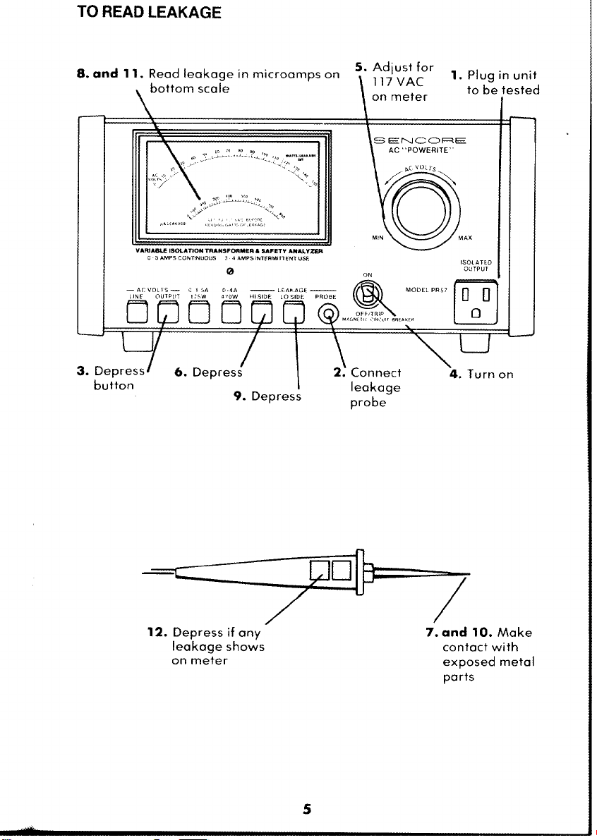
TO READ LEAKAGE
12. Depress if a ny
lea k a g e s hows
on mete r
7. and 10. Mak e
conta c t with
exp o se d m eta l
parts
5
Page 8
DES CRIPT ION
INTRODUCTION
M a ny e l e c t ro nic devic e s t hat op erat e f r o m the AC line d o n ot hav e an
isolati o n tr ans f ormer . So m e o f these ch a ssis have o n e side of t he AC
line connec t ed directl y to the ch a s sis. O t h er devic e s u s e a full-wav e
br i dge rectifie r connecte d to t he ch assis which plac e s the ch a ssis at
one- h a lf th e line vo ltage no matter how t he line co rd is con nect e d to t he
AC line. Th ese chassis must b e isolated fr o m the c omm on sid e of the
AC l ine with a n iso l atio n tr ansfo rm er t o p r event sh ock hazards an d to
prevent t he p oss i bili t y of d am agi ng t he d ev ic e und er te st or t es t
eq uip ment c onne c t ed di r ectl y to the c h a s s i s .
M any new circ u i t tr ouble shoot ing pro c edu r es r e quir e t hat the AC line
vo ltag e be adju stable t o t est regul ators, s h ut-d o wn circuits, a n d o t her
volta ge sen s i t i ve cir cuits. Inc rea sin g or re duc i n g th e lin e v olta ge can
also help loca t e intermi tten t p rob l e ms that do not show up with 117
volts appl i e d t o t he i nput .
Th e abi l i ty to mo nitor t he cu rre nt or po wer d rawn from th e AC line
of t e n si mplifie s trou ble shoot i ng of p o w e r supp l y or p o wer o utpu t
stage pr oble ms. A bno r mal l y hig h pow e r c ons umption in dicates a
pr oble m t hat may not b e i mm e diat ely r e c o g n i z e d bu t wh ic h may c ause
prob l e ms in the f utur e .
Fin ally, every un i t se r v i c e d s h ould be check e d to make sur e that
ex posed me t al p arts do not pose a shoc k h aza r d to the u s e r . A sa f ety
test is r e comme n ded by all manufa ctu r ers . This t es t i s of t en not d o n e
be cause the pr o ced ures g iven in se r v i c e li ter ature a re diffi cult t o per
fo r m an d int erpret .
Th e PR5 7 AC POWE RI TE iM is a n AC s afety s upp l y de sign ed t o ma k e
su r e tha t ev ery f actor re lated t o p o wer is c orrect. The ope r ation is
sim p l if i e d and all of t he fea t ures ne e ded to m e et thes e nee d s ar e includ
ed in a s in g l e , compact i nst rume nt.
FEATURES
Th e Sen c o r e P R57 P OWERITE™ feat ures fo ur f uncti ons in one
compact p a ckag e. Fi r st, the PR57 has a n isolat i o n t ransf orme r t o
isolat e c hassis that hav e o n e s id e c o nnec t e d d i rect l y t o t he AC pow e r
lin e to eli mi nate shoc k hazards dur in g s ervice . T he i so lation
tr ansfo rm er also pr ovides s afe t y for the test equipment and prevents
po s sible da mage to t he set its elf .
Seco nd , t he PR 57 ha s a var iabl e AC tr ansfo rm er that allow s you t o
v ary the isol a t ed A C o ut put volta ge fro m 0 to 140 vol t s AC . You c a n
appl y a hi gh an d low line to ch e c k r egula tor an d shut down circuit
op era t i on or appl y a hig h line to cook out t hat i ntermitt en t tro u b l e .
Page 9
Th i r d, the PR57 meter l ets you m oni t or the AC line vol t age or the AC
vo ltage f rom t he is ola t ed out pu t . T h e met er a ls o allow s you to mon i t or
th e watta ge and curr ent be i ng d r awn by th e unit un der test. The PR5 7
m ete r let s y o u kno w when the vol t age and po wer a r e r i ght.
F ourth , the PR 5 7 pr o vides a safe ty leaka ge te st so you ca n che c k e a ch
cus t ome r’s s et f or AC line l e a kage as re c omm ende d b y mo st manuf ac
ture rs. T here is no ext ernal re sis tor s or meter s t o hook up with t he
PR 57. S impl y de press a b utton, to uch the exp osed meta l parts with
the S afet y Leakage Test Pro be an d r e ad th e l eakage curr en t on th e
m e t e r .
Th e PR 5 7 PO WER ITE™ a lso fe ature s a mag net i c cir cuit brea ker
ba cked up by a 4 A mp slo-b lo fu se. T h e PR 57 is protected, e v en fro m a
di r e c t s hort on the isolat ed output. Th e PR57 a l s o h as only one iso la te d
o ut pu t t o p r ev ent plug gin g in more tha n on e unit and de fea t ing the
isolat i o n of th e i s olat i on tr ansfo rm er and creat i ng a poten tial shock
ha z ard.
SPECIFICATIONS
ISOLATED OUTPUT:
VOLT AGE: 0-140 VAC (typ ical ) c onti nuo usly v a r ia b l e .
CURRENT: 0-3 Amps conti nuous; 3-4 Amps in termittent usa g e (five
m inute s on, five minutes off).
AC LINE LEA KAGE: 50 uA max., eith er isola t ed outp ut t o gr o und.
AC LINE MONITOR:
LINE V OLTAG E: 0-150 V A C ± 3% F.S. (c alibr ated at 117 VAC).
O UT PU T VOLTAGE: 0-150 VAC, ± 3 % F. S . (ca l i b r ated at 117 VAC).
O UT PU T CURRE NT: Ranges: 0-1.5, 0-4 Amps AC; A ccu r a cy a t an y
o utput voltag e: 3% F.S .
O UT PU T WATTAG E: Rang e s: 0-175, 0-470 wat t s; M e t h od: vo lts
time s am ps p r odu c t; Acc u r a c y : 3% F.S. w ith ou tp ut vol t age se t t o
117 VAC.
SAFETY LEAKAGE TEST (Patent Pending):
R AN GE : 0-800 u A , ± 3% F.S . (calibr ated at 500 uA).
M ETHO D: Re f e r ence d to eit her sid e of is olat ed outpu t jack (switc h
selected).
PROTECTION:
AC INPU T: 4 A mp magnetic c i rcu i t b r eak er b uilt i nto p o w e r switc h.
ISOLATED OU TPUT: 4 Am p type 3AG slo-blo fus e on back pane l.
7
Page 10
GENERAL:
METER: 4 V2”, mov i ng coil, 1900 ohm , 100 uA F .S . , diod e pr otecte d
aga inst ove rl o ad ; Accu r ac y: ± 2%.
INPUT P OW ER: 105-125 VA C , .4 Amps idle current w i th no ou tput
loa d with 1 17V AC in put.
SI ZE: 6 ” x 11 Vi” x 12W ’ (15.2 x 29.2 x 32.4 cm.) HWD.
WEIG HT : 18 lbs. (8.2 Kg.)
ACCESSORIES (Supplied):
39G 1 4 8 Saf e ty Leakage Prob e wi t h built - in cali brat ion che ck .
64G 3 5 Le a kage Probe Mount i ng Clip
44G 2 3 Sp are 4 A mp t ype 3AG slo-blo fuse.
Page 11

NOTES
9
Page 12

CONTROLS
1. AC VO LTS L IN E pu shbu t ton: D e pre s s to m oni t or th e A C line
input v o l t age on t he meter (11) u sing the AC V OLTS sc a le ( 1 1A).
2. AC VOL T S OUTPUT pushb utt on : Dep ress to moni t or the AC
volta ge at the I SO LA TED OUTPU T (9). Read the v a l u e o f voltag e on
the met er (11) usi ng the AC V OLT S scale (11 A).
3. 0-1.5A/175W pu shbu t ton: Depress to r e ad curr ent unde r 1.5 a mps
or po wer le s s th an 175 watt s. R e ad value on m e t er (11) us i ng 0-
1.5A/ 1 75 W scale (11B).
4. 0-4A/470W pushbutt on: Dep ress to re ad curre nt to 4 a mps or
power to 470 watt s. Rea d v alue on met e r (11) u sin g scale 0 -4 A / 47 0 W
(11C).
5. HI SIDE LEA KAG E pu shbut ton: De pres s to read AC leakag e
refe r e n c e d to the h i gh (hot) s id e of the AC lin e at ISOL AT ED
O UTPUT ja ck (9). Us e w i th S AF ET Y LEA KAGE PROB E (12)
con n ected to PROBE J ACK (7). Re a d le akag e in mi croamps o n meter
(11) us i ng uA L EAK AGE sc a l e (lid).
6. LO S ID E LE AKAGE pushbutt on : Depress to re ad AC lea k age
refe r en c e d t o th e low (common) sid e of t he AC line at ISOLATED
OUTPUT ja ck (9). U s e w i t h S AFETY LEAKAG E P RO BE (12)
con n e c t e d to PROB E j ack (7). Re a d le akage in m i c roamps on m ete r
(11) us i ng uA LEA KAG E scale (li d).
7. LEA KAG E PR OB E inp ut jac k : Ins ert lea k age pro b e (12) before
m aking lea k age test s using LEAK AGE b uttons (5 or 6).
8. ON - OF F/T RIP swi tc h : C ombinatio n of-off s witc h and m agn etic
cir cuit b r eak er to protect PR 57 ag ain st ov e r l o a d s .
9. ISO LATED OU TP UT soc k e t : For i solated and va r iab l e AC
volta ge for u nit to b e t ested.
10. AC V OLTS co n tr o l : Adjus t s the is olat ed AC ou tput v oltage f ro m
0-140 v olts AC at th e ISOLA TE D OU TPUT so cket (9). Read va r i a ble
volta ge on met er (11) b y depr ess i ng O UTPUT VO LTAG E pu sh bu t ton
(2) using the A C VOL TS sc al e (11 A).
11. M e ter: Provides the f o u r sc a l e s f or vo ltag e, current , powe r , an d
lea k a ge for t he PR5 7 te sts .
11A. A C VOL TS scale : Indic ated by LED when e i t her AC VOLTS
L INE (1) or AC VOLTS OU TP UT (2) pushb utto n is de p r e s sed.
Page 13

IIB. 0-1.5A/175W scal e : In dic ate d by LE D w h e n 0 - 1 .5 A / 17 5 W push
b utton (3) is depres s ed.
IIC. 0-4A/470W sc al e: I ndi cat ed b y L ED wh e n 0-4A /4 7 0 W pu sh
b ut t on (4) is dep resse d .
IID. Le akage scale : In dic ate d by LE D whe n e i t her HI SIDE (5) or
LO SIDE LE AKAGE pushbutton (61 is depr esse d .
12. S afety Lea k age Probe : Used to m a ke all safe t y leak age t ests o n
sets befo r e r eturning them t o the c u stomer .
13. L eakage Te st Switc h : Depre s s ed a fte r a l e a k age rea din g is
obta i ned on m ete r (11) t o i ndi c ate t he tru e leakage in mic r oam ps on t he
leaka g e sc a le (11D) o n the met e r. Wh e n bu tton is not pr essed, in t ern a l
resi sto r prevents mete r fro m pe ggi ng o n high lea kag es and provid es
m e ans of tes ting c a l ibratio n of leakage tes t circ u i t.
Fig. 1 — L o c a t io n of c o ntr ol s a n d feat u r e s of the PR57.
11
Page 14

OPERATION
INTRODUCTION
Bef o r e o perat i ng your PR5 7 for t he first time, take a few minute s to
re ad t hrough the oper ations and applications sec t i ons of the manual.
A cquai nt yo urself w i th the fea t ure s an d tes ts that c an b e per f orm e d
w i th the PR 5 7 . The P R57 is no t o n l y a n i s olat i on tr ansfo rm er, i t i s a
trouble shootin g too l t hat will aid you in the da i l y s e rv i c e as well a s
pr ovide pr ote c t ion against sho c k h azar ds.
POWER CONNECTION
Th e PR5 7 is des i g ned to op e rate from a 105 t o 125 VAC, 60 Hertz
po w er line. Th e PR57 should be p lug g ed into a pro perl y ground ed
th ree wir e o utlet for maxim um s afet y .
MAGNETIC CIRCUIT BREAKER/
POWER SWITCH OPERATION
--------------------------------------
Th e ma gne tic circ uit breaker i s for you r safety and p rotect i on of
th e PR5 7 . Do not def eat its o p erati o n .
The PR 5 7 is prote cte d f r om ove r l o ad by a mag neti c circuit b reak er
bu i l t i nto t he po wer on -off switch . Th e b rea ker interrup ts the AC
pow er appli e d t o the P R57 whe n t r ipped by a n o verload or set to t he
O FF/TR I P p osit i on by hand. T h e ci r cuit bre aker p ort i on is res et after
an overload b y returning th e switch ha n dle t o the ON posit i o n.
I t is nor mal for the circuit br e aker t o allow th e P R57 t o o per ate f or
se v e r a l s econ d s ab o v e the 4 amp rat i ng . The circuit bre ake r will tri p
instantly if a short c i rcu i t is a ppli ed to the ISOLA TE D OU TPUT. Th e
time dela y d uri ng an ove r l oad les s than a dead sh ort will not c a use
damage t o th e PR 57 circu i t s .
SPECIAL NOTES:
1. Aft er a n o v e r l o a d , allow the cir c uit breake r to sit for a few s e c o n ds
befor e r esett ing to all ow the magnetic elemen t s insi d e the b r eak er to
sta b i li z e . At t empti ng t o rese t the breake r immedia t ely aft er it has
tr i pped may res ult i n the break er returning to th e “tripp ed " mode.
2. The br eaker m ay o c casio nally trip wh en turne d to th e ON pos i t i on
ev e n th ou gh t her e i s no o v e r l o a d . Thi s is normall y c aused by t he
WARNING----------------------------------------
Page 15

switc h co nta cts clos i n g at t he p e ak of the AC line vo l t age. Simpl y
repeat the turn- on pr ocess until t he breaker rem ain s on.
3. If the break er will not re ma i n in t he ON po siti on afte r sev e r a l
a ttempts, t he loa d c onnected to th e I SO LA TED OU TPUT may ha v e a
sh o r t c ircui t. Di sc o n ne c t the load, then tur n the MAG NET I C C I RCUIT
B REA KER /POWER switc h o n a g a i n . If the b r eak er conti nue s to t rip ,
the PR 57 m a y hav e an inter nal s hort . Refer to t he “Mai ntenan c e a nd
Se r vice” se c t i o n of this ma nua l fo r d e ta i l s .
FUSE REPLACEMENT
----------------------------------------WARNI NG
Al way s r e p l a c e the f use on t he rear pa nel of the P R57 with a
3AG , 4 Am p slo-blo t ype f u s e , Senc o re part number 44G23, o r its
ex a c t equivalen t . Any o t her ra ting or size f use may cau s e inter n a l
dama ge to th e PR57 a nd will vo i d all war r anti es.
Th e PR5 7 use s an addi t i onal bac k - u p fu s e t o protect the varia ble AC
tr ansfo rm er from d am age wi t h ex c essive c urrent dra wn at low ou tput
vo ltag es. A 3A G, 4 A mp slo-blo fuse, mount ed o n t he r ear pan e l, is in
se ri es with the iso lated output. I f the out put volta ge read on t he P R 57
m ete r drop s t o 0, and t he ma gnetic brea ker ha s not tr i ppe d, c h eck t he
4 Am p fu s e o n the rear pa n e l . If the fuse co ntin ues to b l ow wi t h a uni t
co n nect e d t o the PR5 7 , che c k t he unit fo r a malfu ncti on in the AC
inp ut or power s upp l y circuits .
---------------------------------------
LEAKAGE TEST PROBE MOUNTING CLIP
Fig. 2 — The S afe t y L e aka g e Prob e ma y be s t o re d on t he rear of t he
PR5 7 wi t h the special mo unt i ng clip suppli ed. This ke ep s th e prob e
ha n dy whe n nee d ed to ma ke the Saf ety L e a k a g e Test.
A speci a l mo untin g clip (64G35) is in c l u d ed with th e s pare p ar ts for
the PR 5 7 . This sp ec i a l clip may be mo unt ed on any cle an , d ry su r f a ce
to ho l d the Sa fety Leakage P r o be. Simply peel off th e pa per b ack i ng on
the clip, p l a c e it at t he lo c a t ion to be mou nted , an d p r ess firmly.
Mounting the clip on t he r ear of the P R57 allows t he p r o b e to be s t ored
out of t he w a y and s t i l l be a vailable fo r us e when th e PR57 i s carried to
the job. The clip may also be mo unt ed d i r ectl y to a work b e nch or othe r
su r f a ce n ex t to th e PR57. A ddit i onal clip s m a y be ordere d from the
Sen c o re Servi c e De par tm ent , 3 2 00 Senco re D r., Sio u x Fall s , SD 57107.
13
Page 16

USIN G T HE VARIABLE VOLTAGE OUT P U T FU NC TIO N
Th e PR57 PO WERI TE ™ va r i able vo l tag e out pu t is 0 t o 140 volts AC
RMS. T his can b e very han dy f o r trou blesho oti ng pow er s upply
p roblems, start up c i rcu its an d c he cking circui t re pairs b efo r e
ap ply i ng full v oltage to t h e m. T he t op m eter sc a le r e ads out in AC
volt s R MS so that yo u kno w just ho w much v olt age is a t the
ISOLATED OUT PUT .
---------------------------------------
Ne ver conne c t more t ha n one un i t at a t i me t o the IS OLATE D
O UT PUT. If more t han one unit is co nnec t e d to the o utput of t he
PR 5 7 , i t m ay d efeat t he i s o l atio n b e t ween the u nits a nd may
cr eate a shoc k h aza rd b e t ween uni t s .
To us e the Vari a b l e Outpu t Volt a g e fun c t i o n of the PR5 7 :
1. Plu g the P R57 into a proper l y groun ded t hre e wire AC outl e t.
2. Tu r n the PR 57 ON and de pres s the AC VO L TS O UTPUT push
button. The LE D on the left side o f the AC vo l t s m ete r sca le should
come on.
3. Adjust the AC V OLT S k nob for the desired output voltage a s
in dica t e d on th e met e r .
NOTE : Adjus t i ng th e AC VOLTS c on tro l will cha ng e the AC out pu t
volta ge regard les s of which pu s hb utt on is depres sed.
W ARNING----------------------------------------
USING THE AC VOLTS LINE MONITOR POSITION
Th e P R57 can b e u s ed to m onit or the A C lin e v oltage com i ng in t o your
sh o p or wor k be nch. To moni tor the AC lin e vo l ta ge:
1. Plug th e PR 57 into a pr ope r l y gr oun d ed thre e wire AC o utle t .
2. Depre s s th e AC VOLTS L IN E pushbut ton.
3. Tu rn t he PR57 t o ON wit h th e ON-OFF/TRI P swit c h .
Th e meter wil l n o w rea d the A C lin e volt age bein g ap plied to th e in put
of the PR5 7 . Th e P R57 m ay b e l e f t in t his m o d e anyt im e th at it is not
be i ng used to measure curr e nt, iso l ate a set or mak e l e aka ge t es ts to
act a s a n AC line m onito r .
Page 17

USIN G THE PR57 CUR RE NT FUNCTION
Th e PR57 has tw o c urr ent r a nges, 0-1.5 Amps an d 0-4 Amps. Each
ra nge has its ow n p us hbutton a nd met er scale. T he PR 57 will del iv e r
up t o 3 Amps c onti nuo usly and 3 to 4 Amp s intermitt en t d uty (5
m i nut es on, 5 min ute s off). The current ran ge cal i brat i o n is i nde p en
dan t of the se t ting o f the AC VOL T S cont ro l . Th e me ter is in serie s
wi t h th e ISO LATED OU TP UT a nd measur e s th e ac t ual cur ren t
dr awn by the uni t u nder t es t regar dless of the volt age b eing ap p li ed .
The AC V OLT S c ontr ol onl y n eeds to b e set to th e 117 vo l t set point if
the current re adi ngs ar e be i ng com p ared t o t he full ra ted curre nt con
sum ption of the dev i c e under te st.
To us e t he cur rent fu n c t i o n :
1. Plug the P R57 into a pro perl y gr oun ded t hre e wire o utlet .
2. Turn t he P R57 ON-OFF/TRIP s witc h to t he ON posit i o n.
3. Dep r ess t he AC VOL TS OUTP UT pu sh bu tton an d adju st th e AC
VO LTS c ontr ol fo r the desire d leve l of AC ou tput. T his wo u l d be 117
volts for compa r i ng manufac t urer’s spe c i f i c a t i o ns or a low e r vol t a ge
while t r ouble s hooting a defec t ive circ u i t.
4. P lug the unit to be t ested into t he IS OL AT ED OU TP UT and t urn
the un it on. Dep r ess th e 0- 4 A /4 7 0 W pushbutt on . If th e meter rea ds
les s t han 1.5 Amps, depress the 0-1.5A/ 175W pu sh bu tton and read th e
actu al curr ent on the met er sc a le indicated by the LED.
USING THE PR57 WATTS FUNCTION
Th e P R57 has t wo wattag e ra nge s, 0-175 and 0-470 watt s. E ach range
has it s own p us hb utton and met er scale. Th e P R57 will deli v e r u p to
350 watts con tinuou s l y an d 350 to 470 wa tts i ntermitt en t duty (5
m i nut es on, 5 minutes off). T he wattag e sc al e s are ca l i brat ed at 117
volts AC RMS at the isolat e d ou t l e t .
NOTE: Th e P R57 meas u r es the v o l ts tim e s a mps pro duc t an d does not
tak e the po wer fa ct or of th e circu it in to co nsid eratio n. Th er e may be a
sli g ht di ffe ren ce be tween the t rue w a t ta g e an d th e watta g e sh o wn on
the P R57 me t e r due to th e in d u c t i v e or capa ci tiv e nat u re of s o m e
powe r s upp lies . T h is s l i g ht differen ce can be ignore d in serv ic e work.
To oper ate t he P R57 f o r measu ring watts :
1. Plug th e PR 5 7 into a pr ope r ly grou nded th r ee wi re AC o utlet .
2. Turn t he P R57 ON-OFF/T RIP sw i t ch to the ON po s i ti o n .
15
Page 18

3. D epress the AC VO L TS OUTPU T pushbut to n a nd ad ju st th e AC
VOLTS co ntro l for a re adi ng o f 117 volt s (WAT T S OR LEAKA GE
SET line o n m e t e r ) at the i solated output . The LED will l i ght up
in dicating t he AC VOLT S scale when th e AC V OLT S pu sh butt on is
depres s e d.
4. Pl ug the uni t to be t es ted in t o th e isol a t ed output on the PR57 a nd
turn th e un it ON. Re adjust the AC VO LTS c ontr o l if necessar y to
br i ng the met er back to th e 117 v olt set point on the m e t e r .
5. Depr e ss the 0- 4 A /4 7 0 W push bu t to n a n d note t he r e adi ng on the
m eter scale in dica t ed by t he L ED. I f the reading is be lo w 175 watt s ,
de p ress th e 0-1 .5 A/175W pu sh butt on an d read th e pow e r on t he m e t er
scale indicated b y the LED.
DETERMINING THE WATTAGE RATING OF A UNIT
M ost manufac tur ers will l i st the wa t tage o r c urr ent d raw n b y t he
ele c t ronic d e v ic e o n a p a nel or a pla te near t he A C l in e cord i npu t . Th i s
figu r e c a n be in either amps or watts . If t he f ig ure is i n amps, re ad th e
to p f i g u res of t he s c al e and if in w att s, re a d t he bott om fig ures. These
fig ures will generall y be t he highest allow a b l e levels u nles s othe r wise
list e d .
Som e m anufa cture r s are now li sting the p o wer a s a typi c al p o wer
figu re . Thi s is d e r i ved by finding the maxi mum curr ent a nd the m ini
m um c urr ent an d calculatin g an average figu re . The un i t should be
checked at a no r mal v i e wing level for a TV or a t th e r e com mend ed
o utpu t for a n audi o sys t e m.
If n o figure is li s t ed, ch e c k t he circ uit b rea ker o r fu se ra t i ng. T he
average c urrent dra wn will be a bout % the level of th e fus e or c i r cuit
bre a ker. T h i s is only a guide a nd n ot an ex a ct fig u re . Differen t
man ufact urers may va ry f rom this typica l overr ating of a fuse or
bre a ker. A goo d ide a is t o r e c ord typic al f igure s from p r operly operat
in g set s on t he s chemat i c so yo u hav e a re f e r e n c e t o use w h en s e r vicin g
fu t ure cha ssis of the s ame type .
PERFORMING THE LEAKAGE TEST
Fig. 3 — Th e pu shbu t t on on th e Safe t y Lea k a g e Pr ob e is depre ss ed
when the ac tu a l v alu e of le ak age cu rr en t is to be read on the meter.
16
Page 19

Th e leakage test is perform ed to deter min e if there is a ny AC line
vo ltage lea k age o n any expose d m eta l part of the devic e un der te st.
Any l e a kage ind i cat e s a pot entia l shock h aza r d to anyone touc hin g th e
ex pose d p ar t tha t h as l e a k age. T h i s tes t is f o und on t he sa fety page of
mos t manu facturer’s s ervic e lit era ture and rec ommen ded by all. The
tes t s h ould be pe r f ormed on a compl e t ed u nit that is in the ca binet a nd
re ady to retur n t o t he cust omer. Th e P R57 si mplifie s this leakag e test
wi th the built -i n leakag e circu it a nd spe ci a l S afet y Leaka ge Pro be .
Simply t ouc h th e probe to all e xpos e d meta l pa rts and r ead th e leak
ag e on the m e t e r .
SPECIAL NOTE:
Th e Leak age test must be m ade wi t h no c onnecti o ns to the c hass i s
exce pt the Safet y L eak a ge Prob e . I f any pi e c e of test equipme nt ( oth e r
than th e PR57 ) or an a ntenna is co nnec t e d to the ch a ssis, th e l e a k a g e
re adi ngs may be i n accurat e.
Fig. 4 — The Saf ety Lea k a g e Test s h o u l d be m a d e to all exp ose d m e ta l
parts s uc h as the a n t enna s show n here.
To perfo r m t he Leakag e Test :
1. Plu g th e PR 57 i nto a p r ope r l y gr oun d ed t hre e wire A C o utle t .
2. D epress th e AC VOLT S OUTPUT pu shbutt on and ad j us t t he AC
VOLTS co ntro l for a read ing of 117 v olts on t he PR57 met e r .
3. Pl ug the unit t o b e tested into th e ISO LA TE D O UT PU T on th e
PR57 and tu rn it on. Re adjust t he AC V OLT S con t r o l , if ne c essary, to
re ad 117 vol t s o n t he mete r .
4. Dep r ess th e H I SIDE L EAK AGE pu shbutton a nd pl ug th e
Safe t y Le akage P r obe into the PR OBE jack on th e fr ont p a n el .
5. To u c h t he pr obe t ip to e v ery piec e of exp o s ed me t al, in clud i n g
scr e w h e a ds, a nte nnas, a ntenna ter min als, knobs, all c o ntro l s haf t s ,
w i t h the k nobs r e move d, ha ndles or an ything that eve n appea rs to be
met a l li c .
17
Page 20

6. Depr e ss the LO SIDE LEAKAG E pu sh butt on an d re peat t he
leakage test to th e sa me p oin ts t est ed in step 5.
Th e Saf ety Lea k age P rob e has a sw i t c h whic h p l a ces a curren t - lim i t ing
re sis t or in seri es wi t h t he curre nt tes t cir cuit. Th e re sis t or is bypasse d
wh e n the bu tton on t he probe is de pressed and in seri e s w hen t he p r obe
sw i t ch is in t he n orm a l “ out" pos i ti on.
Th i s r esi sto r lim i t s the amou nt of curr ent to prevent th e meter from
pegg i ng w h e n a test poin t w i t h hi gh l e akag e i s c ontacted. Thi s c ondi
tio n o c c u r s whe n the poi nt b eing tested is c o nnec t e d d i rec t l y t o e i t her
side of t he AC line. The met er is p rot ected ag ainst dam age , e v e n
w i thout th e l i miti ng re sis t or in th e c i rc uit, bu t th e li miti ng re sistor
offe rs add i t i ona l p rote c t i on.
A ny te st point that re ads full scale (800 uA) wi t h t he button in the
“ out” pos i t i on is co n nect e d dire ctly to the side of t he AC line indic ated
by t he LE AKA GE pushb ut t on us e d for that porti on of the saf ety t est .
If, for e x ample, the me t er r e ads full scale w h en t he LO SID E button is
dep r essed, ther e is a dir e ct co nnec t i o n to the comm o n side of t he AC
line. This is the si d e of th e pola r i z e d line cord p lug w ith t he la rger
con n e ct o r .
Le a k age readings , le s s t ha n full scale, i ndicate tha t th ere is a lea k age
p ath ( b u t not a de ad s hort ) to the point being tested . Simply pre ss th e
b utt on o n the S afety Leakag e Probe to read th e a cut al l e a kage curr ent
presen t .
DETERMINING THE ALLOWABLE LEAKAGE LEVEL
The max i mu m al l o w a b l e l e akage level of an ele ctron i c devic e is pri nted
in t he manufac t ur er’s se rvice li t era tur e on th e s afe t y p a g e . T his is the
m axi mum level of l e akage t hat confo r ms w i t h a l l sta ndards to insu r e
custom er s a f ety. The p resent lev e l of leakage on con s um e r elec t r o n i c
dev ic e s is 500 m i c r oam ps. S o me manu factu rer s will publis h a fig u r e
that is lo we r t ha n the 500 m i croamp level a s a s afe ty margin . Che c k
eac h s et to th e manu facturer’s speci fi e d sa f e leak age level.
Se t s ma nuf act ure d prior to 1972 wer e desi gned to me et th e 750 mi c r o
amp le akag e level. Be s ure t o check t hes e sets at t he level specifie d.
TESTING LEAKAGE ON THREE—WIRE UNITS
Th e PR 57 leakage t es t is design ed to op erat e exac t ly th e s ame on a
unit w i t h a two -w i re AC line cor d or a 3-wire (g ro u n d e d) AC lin e cord.
The gro und c onn e c t or on the I SO LA TE D OUTPU T ja ck is connect e d
to earth gr ound thr ou gh t he powe r c ord of the PR57. Th is ass ures s a fe
op era t i on of the un it u nder t est as i t s chas s i s is ma i nta i ned at ea r th
Page 21

po tent i al. Th is ground path do es n o t aff ec t th e safety le ak age test . T h e
lea k age b e t ween th e i nte r nal c ircu i t s and the chassis will be pr oper ly
re ad by sim p ly touching t he Safety Lea kage P rob e to the chassi s . D o
not defeat t he t hird- wire g r o u nd.
CHECKING THE CALIBRATION
OF THE LEAKAGE TEST
Th e c alib r ation of t he P R57 l e a kage t es t can be tested at any ti me so
that yo u will kn o w t hat t he r ead i ngs obtai ned duri ng the test ar e
cor r e c t.
Fig. 5 — Th e built-in cal ibr ation resis to r in the Sa f e ty Lea k a ge Probe
allows a qu i ck check o f t h e lea ka ge scale calibra tio n by i n s e rt i n g th e
Safe t y Le a k age Probe i n to the I s o l a t e d O utp ut a n d c h e c k in g fo r a full
scale leakage reading.
1. P l ug the PR5 7 into a prope r l y gr oun ded th r e e - w i r e AC o utle t .
2. Depr ess t he AC V OLT S OU TPUT and tu rn t he PR57 ON . Ad j us t
the AC V OLT S con t r ol for a r ead ing of 117 volts on th e PR57 met e r .
3. Pl ug th e l e akag e p r obe into the P RO BE jack a nd depr e ss th e HI
S I DE LEAK AGE pushb utton. Pl a c e th e p robe tip i nto th e sm a ll
bla de op e ning of th e I SO LATED O UT PUT soc ket on t he PR57. T h e
met er s h ould rea d 780 mic r oamps (full scale). If the r eadin g i s off,
che c k th e c alibration of the PR 57 usi ng the pr oce dure de s cribed in the
M aint ena nce secti o n of th i s ma n u a l .
NOTE: Be sure t hat the P R57 I SOLATED OUT PU T is se t to 117
volts. The acc ura cy of this setti ng d e t e rmine s the a cc urac y of the lea k
age test.
19
Page 22

APPLICATIONS
TROUBLESHOOTING POWER SUPPLIES
M any p o wer s uppl y tro ubl e s cause t he circuit breake r to trip o r fuse t o
blow on t he uni t unde r test whe n the full A C line vol tage is applied to
the input . This m ake s i t dif f ic ult to lo c ate the d e f e ct causing the
excessi v e c urr ent flow. Many of t hes e po wer s uppl i es will ope r ate
w ith out tri ppi ng the b r eak er or blowi n g t he fuse if the input AC line
vo l t age is red u c ed to a bout 60 v o l ts. At t his level of AC line v o l t a g e,
the r esult an t un regul ate d DC voltages in t he p o wer supp l y will be
about one- ha l f the level n o r mal ly fou n d o n t he s c hema t i c .
The normal a ction of a pow e r sup ply is to i n c r ease t he curre nt f rom t h e
AC line as the AC line v oltage i s i ncreased. At t he 60 volt lev el, the
curr ent drai n sh o u l d be o n e -h a lf o r l e s s t hat o f the full app l i e d A C lin e
vo ltage co n d i t io n . If the dra i n is ex ce s si v e, it indic ates a de f e c t in th e
pow e r su pply or as s oci ated c i r cuits . You may d i s c onn ect loa d c ircui t s
fro m the powe r su ppl y one at a t i me t o is olat e the c i r c uit that is draw
in g the ex c e s s i v e c urre nt.
If the po w e r su pply is used in tu be-oper ated equ i pment, t he o utput
volta g e fro m the sup ply wit h 60 vol t AC lin e inpu t will no r mal l y be
gr eater t han one-half. Thi s is b ecause the f i l aments o f the tubes ar e n ot
wa r m eno ugh t o allow t he t ubes to full y co nduct. Y o u may s lowly
incr e a s e t he ap plie d volt a ge in t hese case s unt i l the tub es beg in to
co ndu ct or t he ci rcu it bre ake r on the un it be i ng tes t ed tr i ps. Then
redu c e the AC vol t age f r o m the PR5 7 un t i l t he set will ope r ate wit hout
tr i pping t he br e a ker. This will all ow you to ma k e measur ements to
lo c a t e the defe c t.
If th e br e ake r will no t trip until the t ubes a r e warm e nou g h to c o nduc t ,
a tube may have a short o r o t her internal pr oblem caus ing the tr o uble .
TROUBLESHOOTING CONSTANT VOLTAGE
TRANSFORMER POWER SUPPLIES
Th e co nstant volta ge tran s for me r u ses a c apa c itor a cross a s econdar y
wi ndin g th at “t une s” t he t ran sform e r. This ca pac itor is g e n eral ly
about a 2 to 5 micr ofarad oil-filled ty pe. The seco nda r y vol t age of a
con sta nt vo l t age transformer re mai ns co nst an t ov e r a wide r ang e of
in put vo l t age s . In m a ny case s , the c apa citor o p ens and th e def ect is
not notice d unle s s a w id e r a nge o f AC v olta ge is a p plie d to t he cir c u i t.
Th e constant volta ge tr ansfo rm er and capa c itor can be check e d an d
trouble s l ocat ed in the su pply by l o werin g t he a ppli e d AC v olta g e. T h e
no rma l a ctio n of the “tu ni ng” of t he c apa citor ca n readil y be seen if
the v o ltage is incre ased from about 60 vol t s to 90 vol t s AC w h il e moni
Page 23

toring the AC cu r rent o n the PR57. The curre nt will i n crea s e to a leve l
hi g her tha n the n ormal cur rent at 117 vo l t s as t he tr ans for me r
attemp s to k e e p the o utput v oltage at a constant level. When the i nput
voltage s r e ach e s about 90 volts , the tuning will t ak e e ff e ct and t h e
curr ent will start to decr e ase as th e vo l t age is in c r e a s e d .
As th e v o ltage is inc reased furt her to 117 v olts, the curr ent will
de c r ease an d dip a t arou nd 117 vo lt s . If t he vol t a ge i s inc r eased
fu rther, t he curr en t will a gai n b e gin to inc r e a s e . If a cons tant volta g e
tr ansfo rm e r cir c uit d o e s not exh i bit th i s ch a nge i n cur rent with cha n g e
in volta g e, eit her the ca pacitor is open or t he tuni ng winding on the
tr ansformer is open.
NOTE: T he se co nd a ry vo lt a ge wave f o rm is a squar e w av e in a pr op e rl y
ope r a tin g con s t a nt v o lt ag e trans for mer . Use a scope or a D VM wit h a
true R M S func t i o n to meas u re th e v o lt a g e accura tely.
CHECKING CIRCUIT REPAIRS AT REDUCED
INPUT AC VOLTAGES
A f ter r epa i rs h ave b e en made to powe r s u p p l ie s , h orizon t a l o utpu t
ci r c uits or si milar powe r ty pe circ uits, th e u nit sho uld be test ed at a
red u ced i np ut voltag e. T h i s will red uce the possi bilit y of damage if
th ere is s t i l l another p r oble m in th e circ uit. Th e lo w e r ed AC input
vo ltage will allow the set to operate at reduce d pow e r and giv e you
time t o see if further rep air s a r e necess ary. A goo d p l a c e to st art is at
about 85 vo lts AC. S l ow l y increase the vol t age w hil e m oni t oring the
curr ent on t he PR57 me t e r . If the curre nt i ncre ases beyond the n orma l
lim i t s , turn t he power t o the PR57 OFF a nd r ec h e c k th e circ uit for a
ma l f u n c t i o n .
NOTE: In tu b e-o p era te d equ i pment, allow t im e for the filame n t s to
war m up as y o u incre ase the in put voltage. I f y ou a d j ust th e in p u t too
fast, t he tub e s will n o t h a v e a ch ance to warm up and th e exce s s iv e
cur re n t pr o b le m m ay no t sho w up u n t il i t is too late. A l low ab o ut two
seco n ds for each f i v e vo lt s t hat y ou increase th e i n put v o lta ge for the
tub e s to reach o pe r a ti ng te mp era tu re.
REFORMING POWER SUPPLY
ELECTROLYTIC FILTERS
Th e P R57 vari able AC v oltage ca n be us ed to r efor m the elec t r olytics
on old e r sets t hat hav e b een s itt ing for a l o n g pe r i od of tim e . The
electr olytic f i l t ers in the pow e r s upp ly co u ld be l e a ky an d should b e
operated at a low e r inp ut v oltage firs t a nd then ha v e t he volt age
in c r e ased slowly t o th e co r r ect o per ating p o i nt. This will p revent g a s
bui ld - u p a nd po ssib l e d amage to the c a paci t ors. Simply plu g the unit
in t o t he ISO LATED OUTP UT o f t he P R57. Se t the A C VOLTS
a dj us t to 60 vol t s , a n d a llow the se t to oper ate for 5 to 10 m inutes.
21
Page 24

Obser ve the c urr ent on the PR57 met e r . It s h o uld d e crease as t he c apa
citors re f orm the insula ting d i e le c t r ic mater i al. I ncr e ase the vo l t age in
5 vo lt steps and wat ch to see if th e curr ent decrea s e s , indicat i ng t he
capa citors are refor min g af t er e a c h vol t age inc r e a s e . I f t he cur r ent
in c r ease s abo v e th e norm al rati ng of the se t and doe s no t co me dow n , a
de f e ct i n t he po wer sup ply or oth er ci rcu i t s is in dica t ed. Th e cir cuit s
m ay be furth er tested at r e duc ed voltag e to prevent a ddi tional cir cuit
da mag e .
CHECKING THE WIRING OF THE AC LINE CORD
AND POWER SWITCH
To meet all st anda rds, a p o larized line cord mu st be use d on all
ch ass i s w h er e one s id e of the AC line is co nnected directl y to the
ch a s sis. The AC on-off s witc h on all set s must b e w i r e d t o interr upt t he
ho t sid e of th e AC po wer line. Both co nditi ons ca n b e qu i c k l y checke d
w i t h the PR 57 l e a k age p r obe a nd HI and LO si d e le aka ge test .
To che ck t he wirin g of the A C line cord:
1. P l ug the unit t o b e t ested in t o th e ISO LATED OUT PU T on the
PR 5 7 and turn b oth un its ON.
2. D epress th e LO SIDE LEA KAGE te st pushb utt on . Us e the
Sa f ety Le a kage P r obe to ma ke con t act wit h the me t al chas sis of th e
unit under te st. If the cold or g r ounde d side of th e line is prope r l y
wire d to th e c hass i s, the PR57 meter will rea d full scale. N o met er
def le c t io n indicates t hat the c o r d is w ir e d improper l y. NOTE: D o n o t
dep re ss the l eak ag e button on t he S afety L eakage Pro b e fo r the ab o ve
test.
To chec k the wir i ng of th e ON-OFF s w itc h :
1. P lug t he u nit t o b e t ested in t o th e ISO LATED OUT PU T on the
PR 57 a nd tu rn b oth units ON.
2. Depr e ss the HI SIDE l e a kage tes t but ton. Us e t he Saf ety Le a k
ag e Pr obe to ma ke co nta ct wi t h t he AC l in e term i nals on th e on-off
swi tc h . I f t he m e ter re ads full scale de f le c t i o n , the sw i t c h is cor rect l y
wir e d into the hot s ide of the AC line. No def l e c t i o n on the me t er
indicates t he s witc h i s wire d t o the w rong side o f t he AC power line.
NOTE: Do not d e pr es s the lea kag e bu t t o n on the S afe ty Le a k age
Prob e for th i s test.
Page 25

TESTING TRANSFORMER OPERATED DEVICES
FOR AC LEAKAGE
Th e pow e r tra nsform er u sed in e l e c t r o n i c e qui pment should isolate th e
chas s is o f t he equi pm ent fro m t he AC power line. The r e are oc c a si o n s
wh e r e the tran sfo rmer may inter nal l y s h ort; prim ary to the frame or
primary to se c o ndar y. Thi s r esult s in a ho t chass i s . So m e sets ha v e
byp ass c apa citors fr o m e ach sid e of t he AC lin e to the chas s is to
byp ass RF in t e r f e r e n ce. A shorted or lea ky bypass c apa cito r will also
result in a hot chas s i s . Eithe r of the se c ond it ions will be lo c ated by per
fo r min g t he Safety L e aka ge T est. The circ uit faul t is e asie r t o locat e
by noti ng which LE AKAG E bu tton is pr e sse d for the h i gh leakage
rea ding . If, fo r e x a mple , the hig hes t lea kage read is obt ain ed when the
HI SID E button is pr e ssed, the l e akage is fo ll owing the path for th e
hot sid e of the po larized PR57 output j a ck. The l e a kage pa th may be
tr ace d t hrough th e power c o r d by simpl y touc hin g the Safe t y L e a k age
Pr obe to bo t h s id es of t he AC line c o r d ins ide t he unit u nder te st wit h
th e HI SIDE button (in this e x a m pl e ) pres sed. The me t er will re ad full-
scale w hen the c orre c t s ide of the AC line is c onta cted.
READING AC LEAKAGE LEVELS BELOW
100 MICROAMPS
Th e PR5 7 i s d e sign ed to cov er the n orm al r ange of A C le akage fou n d
in c ons ume r electron i c s , 100 to 800 micr o amp s . It is ofte n d e sira ble to
re ad le akage current s belo w 100 micr o amp s . Th i s can be a c c omp l is hed
by using a D V M that will r ead AC curr en t below 100 uA, such a s t he
Sen c o r e D VM3 7 or DV M38. Just follow this proc e d u r e :
1. C o nnec t the co mmo n lea d of th e DVM to t he PR OB E inp ut jac k
on the P R 5 7 .
2. Pl ug the un i t to be test ed f o r le a kage into t he isolat ed o ut pu t on
the P R57 and turn both units on.
3. D epr ess th e AC VOL TS OUTPU T pus hb utton and adjus t t he A C
VOLT S contro l for a r ead ing of 117 v olts on t he P R57 meter.
4. D e press the HI SI DE L EAK AGE p ushb utt on. Us e the DVM
met er pr obe t o touch the p oints th at wou ld n orm a l l y be tested with t he
Sa fety Leak age P robe. Read the le aka ge current on the DV M .
5. D e pre s s t he L O SI DE LE AKAG E pu sh bu tton and rep eat ste p 4.
23
Page 26

MAINTENANCE
-----------------------------------
These serv icing i nstructions are for use by qua lified personnel
only. To avoid electric shock, do not perform any serv icing other
than that contained in the operating instructions unless you are
qualified to do so.
WARNING-----------------------------------
DISASSEMBLY INSTRUCTIONS
1. Set t he PR 5 7 in its n orm al o perat i ng posi t ion. R emov e t he two
scre w s s e curi ng th e t op to t he en d cap with t he ha ndle. The s e a r e t he
scre w s d i r ectl y above the ha n d l e .
2. Set th e P R57 on th e e nd wit h t he han dle. Rem o v e the five scre ws
se c u r i ng the e n d cap to th e case. D o not r e move the t wo scre ws
se c u r i ng t he e n d ca p to th e t op as the en d ca p and top will b e remove d
as on e piece.
3. Car e fu l l y lift th e end cap and top away from the case. T h i s will
exp o se th e in t ern al contr ols a nd PC boar d for calibrat ion a nd se rv ice.
To re move t he P C boar d fro m th e PR 57 :
1. R e move the e n d c a p an d to p as desc r i bed a bo ve .
2. Unplug t he fo u r c onn ecto rs g o i n g to t he PC b o a r d.
3. Re move the tw o sc r e ws se c uring the PC boa r d t o the ca s e. Thes e
mu st be remov e d from th e b ott om of the case.
4. Caref u l ly pu l l the PC bo ard bac k an d up sl i ghtl y away from the
fr ont pane l . No t e t hat there a re tw o m ounti ng pin s o n the fr ont p a n e l
that sec u r e the switches and PC b o a r d. Pul l t he PC board bac k p ast
these pin s to d i s engage i t t otally fro m th e case.
5. To rep l a c e the PC b oard , rev erse the a bove p roce dure being sur e
that the pins on t he fro nt p a n e l are a l i g ned wit h th e hol es i n the switch
brac ket b e fo r e p ushing the a ssemb l y forward.
PR57 CALIBRATION PROCEDURE
--------------------------------------WARNI NG--------------------------------------
The following procedure is intended for use only by a qualified
technical person who understands the po tential shock hazard
that exis ts with the PR57 cover removed. Do not touch any of the
internal terminals or exposed leads from the AC load. Make test
equipment connections to the PR57 or the AC load ONLY when
the power to the PR57 has been turned OFF. Only use an
insulate d screwdriver to make the internal adjustments.
Page 27

E quipme nt re q uire d for ca l ibrati o n:
1. Accurate DVM capab l e of mea suring both A C volts ave r age RM S
and 2A AC cur ren t avera ge R MS.
2. Res i s t ive AC lo a d cap a ble of dra win g 1.0 t o 1.5 a mps . A 100 watt
light b ulb can be us ed a s a load.
3. I nsula ted scr e wdriv e r .
Light Bulb
AC Load
Fig. 6 — AC load an d DV M conn ec ti on s for calib ratio n of PR5 7 1.5
Amp c ur r en t scale.
Th e follo w in g pro c e dure is use d t o c alibra t e the PR57. T he contr ols
mu st be ad j us t ed in the follow i ng o r der t o insur e proper cali b r ation .
1. Disass emble th e PR57 as descri b e d in the Disassembl y i nstruc
tio n s . Do n ot p l ug the P R57 i nto t he AC power line at t his time.
2. Conn ect a DVM, s et to measure AC curr ent, in serie s with t he AC
load. Conn ect t his se r ie s combina t i on t o the P R 5 7 IS OL AT ED
O UTPUT. Se t th e A C VO LTS co n t r o l to m i nimu m o r fully counte r
clockw is e.
3. D epress the 0 -1 .5 A /1 7 5 W pushb utt on, plug the PR57 i nto the AC
power line and tu rn t he ON -OFF / TRIP s witc h t o ON.
4. Adjust t he AC V OLTS c o ntro l while observ ing the DVM. Se t th e
co ntrol f or a con v enient D V M re ading ove r 1 Amp, such as 1.2 or 1.3
Amps .
5. Ad just t he 1.5A C AL co ntro l (R12) until t he PR5 7 m eter reads the
sa me c urr ent as the D V M .
25
Page 28

6. Turn the pow e r t o th e PR 57 OFF .
7. Conn ect th e DVM, set to measu r e A C volts ave rag e RMS , to the
PR57 I SOLATED OU TPUT. Depres s the AC VOLTS OUTPU T push
button .
8. T urn th e PR57 ON an d adju st the AC VO LTS control u ntil the
DV M r e ads 117 vo l t s . Ad ju st the V OLTA GE C AL control (R6) on th e
PC b oard until the PR5 7 me t er r eads 117 vo l t s ( WATTS O R
L EAK AGE S ET line on t he meter scale). T hen di s con nec t t he D V M .
9. Depre s s the HI SIDE leaka ge pushbutton. Conn ect th e Saf ety
Leak age Pro be t o t he P ROB E j ac k o n th e PR5 7. I nsert the p rob e end
into the small prong (r i ght side) of the ISO LATED OUTPUT . T he
PR57 me t er s houl d be 78 0 m i c r oam ps. NO TE: Do n o t d e pr es s th e
leak ag e b u t t on on t h e Safety L e a kag e Probe.
10. Ad j us t the L EAKAG E CAL C ONTROL (R2) on t he PC board
for a re adi ng of 780 microa mps on the le a kage scal e of the meter.
Th i s completes the cal i bra t i on o f the PR57. A peri o d i c chec k can be
ma de of t he l e akage cali bra t i on b y simply inser t ing t he Safet y
Le akage Pro b e in t o t he I SOLAT ED OU TP UT an d c h ecking f o r full
scale d e f le c t i o n a s d escr i bed in t he a b ove calibra t i on pr o c e dure .
Page 29

N OT ES
2 7
Page 30

SERVICE & WARRANTY
Warranty
Your PR57 “AC Powerite” has been built to the highest quality standards in the
industry. Each unit has been tested, aged under power for at least 24 hours, and then
retested on every function and range to insure it met all published specifications
after aging. Your instrument is fully protected with a 1 year warranty and Sencore’s
exclusive 10 0% Made Right Lifetime Guarantee in the unlikely event a
manufacturing defect is missed by these tests. Details are covered in the separate
booklet. Read this booklet thoroughly, and keep it in a safe place so you can review it
if questions arise later.
Service
The Sencore Factory Service Department provides all in- or out-of-warranty service
and complete recalibration services for Sencore instruments. No local service
centers are authorized to repair Sencore instruments. Factory service assures you of
the highest quality work, the latest circuit improvements, and the fastest turnaround
time possible because every technician specializes in Sencore instruments.
Sencore’s Service Department can usually repair your instrument and return it to
you faster than a local facility servicing many brands of instruments, even when
shipping time is included.
You do not need authorization to return an instrument to Sencore for service. Be sure
you include your name and address along with a description of the symptoms if it
should ever be necessary to return your instrument. Ship your instrument by United
Parcel Service or air freight if possible. Use parcel post only when absolutely
necessary.
Be sure the instrument is properly packed. Use the original shipping carton and all
packing inserts whenever possible. If the original packing material is not available,
make certain the unit is properly packed in a sturdy box with shock-absorbing
material on all sides. Sencore suggests insuring the instrument for its full value in
case it is lost or damaged in shipment.
A separate schematic and parts list is included if you wish to repair your own
instrument. Parts may be ordered directly from the Factory Service Department.
Any parts not shown in the parts list may be ordered by description.
We reserve the right to examine defective components before an in-warranty
replacement is issued.
SE NCORE FACTORY S ERVICE
3200 Sencore Dri ve
Sioux Fall s, S D 57107
I-8OO-SENCORE
FAX: 605/335-6379
Fill in for your records
Date Purchased:
Serial Number
Run Number____________________________________________________________
(NOTE: Plea s e r ef e r to t h e ru n n um b er if it is n e c e s s a r y to call th e Se r v i c e Dept.
The run n um b er m ay be u p d a t e d w h e n the unit has be e n r e t u r n ed for se r v ic e . )
________________________________________________________
__________________________________________________________
Page 31

S E I V J C O F R E
ELECTRONIC TEST EQUIPMENT
Innovatively Designed With Your Time In Mind
Phone T oll-Free 1 - 8 0 0 - S 5 r v iC O F :t S
Page 32

PR57
P OW E RITE ™
Schematic and Parts List
S ENCORE
AC “ POW E RI TE ”
VARtASL K ISOLATION T HAH SFORMB HA SAFET Y AN ALYZER
0 - a AM PS CO NT INU OUS 3 * 4 A MP S INTERM ITT ENT USE
— AC VOL T S— 0-1 .5 A
LINE OUTPUT 17SW
0-4 A
470W
□ □ □ □ □ □
- LEAKAG E --------------
HI 5I DE 1 0 SIDE PROBE
OFFrTHlP
MAGNETIC CmCUIT BKAKEH
u n u i' • u o mokm on»t«»
S E N C O R E
3200 Sencore Drive, Sioux Falls, South Dakota 57107
ISOLATED
OUTPUT
• ■1MVACMA m t to
Q D
Q
Page 33

Foil Side
Page 34

Component Side
SENCORE 43BI65-A
Page 35

PA RTS LIST
SCHEMATIC
REFERENCE PART NO.
P.C. BOARD ASSEMBL Y 100 BOARD
CR1
CR2, 3, 5, 6
CR4
CR7, 8
SW1
R1 14A52-18
R2 15C7-14
R3
R4 14A72-4
R5
R6
R7
R8
R9
RIO 14C5-470 Resistor, 47 ohm V4W, 10%
R ll
R12
R1 3, 14
Cl
C2, 3, 4
C5
EYELET BOARD & CHASSIS
CR201-204
Ml
*T1
*T2
•SW1
*F1
16010
50C3-2 J
50C5-2fA
50C4-11
25A287J&
14C5-122
14A52-19 Resist or, .7 ohm 10W, 5% W.W.
15C7-6 Control, 500K Vert P.C. Linear
14C5-125 Resistor, 1.2M ‘/sW, 10%
42E11 Resistance Wire .287 ohm/ft.
14B49-3 2 Resistor, 8 .2K 5W, 10% W.W.
14C5-103
15C7-2
14B49-10
24G223
24G207
24G382
20G18
23C70
28K77
28K78
25G28 4
8B245
44G23
39G14 8
DESCRIPTION
Diode, 1N40 04 1A 400V PIV
Diode, 1N695
Diode, 1N41 48
Diode, 15V Zener
Switc h, 6 station pushbutton
Resistor, 10K 10W, 10% W.W.
Control, 5K Vert P.C. Linear
Resistor, 1.2K V*W, 10%
Resis tor, 1.33 ohm 22W, 5%W.W.
Resist or, 10K V4W, 10%
Control, 10K Vert P.C. Linear
Resis tor, IK ohm 5 W, 10%
Cap., .15 uF Radial Lead Mylar
Capacitor, .01 uF dis.
Capacitor, 10 uF Lytic
LED Indicator, Mini
Meter, 100 uA 1900 ohm
Transformer
Transformer, Variable
Switch on/off w/circuit breaker
Escutcheon, Front Panel
Fuse, 4A Slo Bio
Leakage Probe
* Replace only with e xac t manufacturer parts.
Prices in effect at date of pr inting and are subject to change without
notice. When ordering parts, please specify model number, part number,
and description. Service and parts invoices are C.O.D. Pl ease include
rem ittance (check or money order) with your order to save C.O.D.
charges . Minimum billi ng $5.00.
5 P = M C O R I
Page 36

NOTES:
1. See parts list for safety critical parts. Use only
exact replacement for continued safety.
2. All resistances are in ohms.
3. All capacitances greater than one are pF, less than
one uF, unless otherwise indicated.
4. All controls and jacks on the outside of the unit are
shown in a box
BLACK
GREEN
m
 Loading...