

Page 1

January 2018
Form 8166A www.sencore.com | 1.605.978.4600 Revision 1.2
MIP 6210
High Rate IP Streamer
User Manual
Page 2

MIP 6210 – User Manual
Page 2 (75)
Copyright
© 2018 Sencore, Inc. All rights reserved.
3200 Sencore Drive, Sioux Falls, SD USA
www.sencore.com
This publication contains confidential, proprietary, and trade secret information. No part of this document
may be copied, photocopied, reproduced, translated, or reduced to any machine-readable or electronic
format without prior written permission from Sencore. Information in this document is subject to change
without notice and Sencore Inc. assumes no responsibility or liability for any errors or inaccuracies.
Sencore, Sencore Inc, and the Sencore logo are trademarks or registered trademarks in the United States
and other countries. All other products or services mentioned in this document are identified by the
trademarks, service marks, or product names as designated by the companies who market those products.
Inquiries should be made directly to those companies. This document may also have links to third-party web
pages that are beyond the control of Sencore. The presence of such links does not imply that Sencore
endorses or recommends the content on those pages. Sencore acknowledges the use of third-party open
source software and licenses in some Sencore products. This freely available source code can be obtained
by contacting Sencore Inc.
About Sencore
Sencore is an engineering leader in the development of high-quality signal transmission solutions for the
broadcast, cable, satellite, IPTV, and telecommunications markets. The company's world-class portfolio
includes video delivery products, system monitoring and analysis solutions, and test and measurement
equipment, all designed to support system interoperability and backed by best-in-class customer support.
Sencore products meet the rapidly changing needs of modern media by ensuring the efficient delivery of
high-quality video from the source to the home. More information about Sencore is available at the
company’s website, www.sencore.com.
All trademarks and registered trademarks mentioned herein are the property of their respective owners.
Page 3

MIP 6210 – User Manual
Page 3 (75)
Revision History
Date
Version
Description
Author
8/9/2017
1.0
Manual for the Sencore MIP 6210
GAK
8/10/2017
1.1
Edits and cleanup
SV
1/05/2018
1.2
Add Record, Licensing Features
GAK
Page 4

MIP 6210 – User Manual
Page 4 (75)
Safety Instructions
• Read these instructions
• Keep these instructions
• Heed all warnings
• Follow all instructions
• Do not use this apparatus near water
• Clean only with dry cloth
• Do not block any ventilation openings. Install in accordance with the manufacturer’s
instructions
• Do not install near any heat sources such as radiators, heat registers, stoves, or other
apparatus (including amplifiers) that produce heat
• Do not defeat the safety purpose of the polarized or grounding-type plug. A polarized
plug has two blades with one wider than the other. A grounding type plug has two blades
and a third grounding prong. The wide blade or the third prong is provided for your safety.
If the provided plug does not fit into your outlet, consult an electrician for replacement of
the obsolete outlet.
• Protect the power cord from being walked on or pinched particularly at plugs,
convenience receptacles, and the point where they exit from the apparatus.
• Only use attachments/accessories specified by the manufacturer.
• Unplug this apparatus during lightning storms or when unused for long periods of time.
• Refer all servicing to qualified service personnel. Servicing is required when the
apparatus has been damaged in any way, such as power-supply cord or plug is
damaged, liquid has been spilled or objects have fallen into the apparatus, the apparatus
has been exposed to rain or moisture, does not operate normally, or has been dropped.
• Do not expose this apparatus to dripping or splashing and ensure that no objects filled
with liquids, such as vases, are placed on the apparatus.
• To completely disconnect this apparatus from the AC Mains, disconnect the power supply
cord plug from the AC receptacle.
• The mains plug of the power supply cord shall remain readily operable.
• Damage Requiring Service: Unplug this product from the wall outlet and refer servicing
to qualified service personnel under the following conditions:
o When the power-supply cord or plug is damaged.
o If liquid has been spilled, or objects have fallen into the product.
o If the product has been exposed to rain or water.
o If the product does not operate normally by following the operating
instructions. Adjust only those controls that are covered by the operating
instructions as an improper adjustment of the controls may result in damage
and will often require extensive work by a qualified technician to restore the
product to its normal operation.
o If the product has been dropped or damaged in any way.
o The product exhibits a distinct change in performance.
• Replacement Parts: When replacement parts are required, be sure the service
technician uses replacement parts specified by Sencore, or parts having the same
operating characteristics as the original parts. Unauthorized part substitutions made may
result in fire, electric shock or other hazards.
Page 5

MIP 6210 – User Manual
Page 5 (75)
SAFETY PRECAUTIONS
There is always a danger present when using electronic equipment.
Unexpected high voltages can be present at unusual locations in defective equipment and signal
distribution systems. Become familiar with the equipment that you are working with and observe
the following safety precautions.
• Every precaution has been taken in the design of your MIP 6210 to ensure that it is as
safe as possible. However, safe operation depends on you the operator.
• Always be sure your equipment is in good working order. Ensure that all points of
connection are secure to the chassis and that protective covers are in place and secured
with fasteners.
• Never work alone when working in hazardous conditions. Always have another person
close by in case of an accident.
• Always refer to the manual for safe operation. If you have a question about the
application or operation call Sencore for assistance.
• WARNING – To reduce the risk of fire or electrical shock never allow your equipment to
be exposed to water, rain or high moisture environments. If exposed to a liquid, remove
power safely (at the breaker) and send your equipment to be serviced by a qualified
technician.
• To reduce the risk of shock the MIP 6210 must be connected to a mains socket outlet
with a protective earth ground connection.
• For the MIP 6210 the mains plug is the main disconnect and should remain readily
accessible and operable at all times.
• To reduce the risk of shock and damage to equipment, it is recommended that the
chassis grounding screw located on the rear of the MIP 6210 – be connected to the
installation’s rack, the vehicle’s chassis, the battery’s negative terminal, and/or earth
ground.
Page 6

MIP 6210 – User Manual
Page 6 (75)
Table of Contents
1 Introduction ...................................................................................................... 8
2 Specifications ................................................................................................... 8
3 Getting Started ............................................................................................... 10
3.1 Introduction .......................................................................................................................... 10
3.2 Package Contents ............................................................................................................... 10
3.3 Installation ........................................................................................................................... 10
3.4 Rear Panel Connections ..................................................................................................... 12
3.5 Power Connections - Installation ......................................................................................... 12
3.6 Front Panel Features .......................................................................................................... 13
3.7 Obtaining the MIP 6210 IP Address .................................................................................... 14
3.8 Unit Networking and DNS Configuration ............................................................................. 15
3.9 Controlling the MIP 6210 Using the Web GUI .................................................................... 17
3.10 Simplified Startup - Getting a Stream Playing ................................................................... 19
4 Play Control Panel ......................................................................................... 24
4.1 Play Control Panel Overview .............................................................................................. 24
4.2 Stream/PCAP Information Overview ................................................................................... 25
4.3 Player - Adding a Transport Stream .................................................................................... 26
4.4 Adding a PCAP Play File .................................................................................................... 30
4.5 IP Stream and PCAP Status & Configuration Information .................................................. 34
4.6 IP and PCAP Monitor Panel ................................................................................................ 36
5 File Viewing Panel .......................................................................................... 38
5.1 FTP - SMB Loading Play Files to the MIP 6210 ................................................................. 39
5.2 File Transfer Management - User Name and Password..................................................... 41
5.3 Managing Play Files & Folders ........................................................................................... 42
5.4 File Viewing Panel – Filter by Type ..................................................................................... 42
6 Record Panel .................................................................................................. 43
6.1 Record Panel Overview ...................................................................................................... 44
6.2 Record – Information Fields ................................................................................................ 45
6.3 Recording Input TS Stream Configuration .......................................................................... 46
6.4 Recording Input PCAP - Configuration ............................................................................... 50
6.5 Record Status & Configuration Information ........................................................................ 54
6.6 IP and PCAP Monitor Panel ................................................................................................ 57
7 Admin .............................................................................................................. 59
7.1 Changing Unit Password ..................................................................................................... 60
7.2 Profile Manager ................................................................................................................... 60
7.3 SNMP MIB Files .................................................................................................................. 61
7.4 Diagnostics .......................................................................................................................... 61
7.5 Update the Unit Software Version ....................................................................................... 62
7.6 Reboot Unit ......................................................................................................................... 63
7.7 Reset Unit to Factory Defaults ............................................................................................ 63
7.8 General Configuration ......................................................................................................... 63
7.9 Network Port Configuration ................................................................................................. 64
7.10 Licensing Configuration ..................................................................................................... 65
7.11 Date/Time Configuration ................................................................................................... 67
7.12 SNMP Communities .......................................................................................................... 68
7.13 SNMP Trap Managers ...................................................................................................... 68
7.14 Syslog Configuration ......................................................................................................... 69
8 Reporting Panel ............................................................................................. 70
8.1 Active Alarms ...................................................................................................................... 70
8.2 Event Logs .......................................................................................................................... 71
8.3 Configuring the Logs ........................................................................................................... 73
Page 7

MIP 6210 – User Manual
Page 7 (75)
9 About Panel .................................................................................................... 74
Page 8

MIP 6210 – User Manual
Page 8 (75)
1 Introduction
The MIP 6210 High-Rate IP Streamer aids in the design, verification, manufacturing, and
deployment of digital TV equipment and systems. The ability to play out hundreds of media
streams at Gigabit rates makes it the ideal solution for the development and deployment of IPTV
systems. It further serves as a reliable signal source for qualifying IPTV networks and digital
television equipment. With its full line-rate performance, the MIP 6210 is the ideal tool to test the
limits of networks and IP devices.
The intuitive web UI and full SNMP or web API remote control allows the MIP 6210 to offer users
reliable and powerful solutions for operational and lab environments. It offers multiple output
ports and numerous expansion options.
This manual provides startup and operational information. It is written for professional operators
of video distribution systems and assumes a prerequisite level of technical knowledge.
2 Specifications
Physical Interfaces
2 x RJ45 1Gbps Ports Included: (Use for streaming and/or management)
Additional Options: 2 x RJ45 1Gbps, Fiber 2 x SFP 1Gbps Optional Ports
Management Interfaces
Webpage User Interface, Web Service API
MPEG over IP Streamer
Full line rate streaming
PCAP, MPEG transport stream files supported
Seamless looping
Full transport parameters control (IP addresses, UDP ports, RTP)
MPEG over IP Recording
Capture to PCAP, MPEG transport stream files supported
Immediate record start or scheduled start
Full transport parameters control (IP addresses, UDP ports, RTP)
PCAP filtering
Performance
Cumulative Throughput: 1Gbps (Disk to all outputs)
1Gb Ports Streaming: Up to 1Gbps
Stream Storage Capacity: 1TB
Page 9

MIP 6210 – User Manual
Page 9 (75)
Dimensions/Power
Size: Rack-mount 1 RU chassis
Depth: 20 inches (507 mm)
Power: 100-240V, 50-60Hz
Specifications are subject to change without notice.
Page 10
MIP 6210 – User Manual
Page 10 (75)
3 Getting Started
3.1 Introduction
This section provides an overview of what is included with your MIP 6210. It provides critical
information on obtaining the unit’s IP address in which to gain access to the unit’s web interface
GUI. It provides front/rear panel descriptions and information on getting the unit mounted in a
standard rack.
3.2 Package Contents
The following is a list of the items that are included with the MIP 6210 unit:
1. Startup Guide
2. AC Power Cord
3. Rackmount Rails
If any of these items were omitted from the packaging of you unit, please call
1-605-978-4600 to obtain a replacement.
3.3 Installation
The MIP 6210 rackmount chassis is a 1RU enclosure that is designed to be mounted in a
standard 19” equipment rack. The unit is shipped with the mounting hardware necessary to safely
secure the chassis in the rack. This includes rackmount ears and screws for the front along with
rails to support the sides. The user is advised to always use the included rails for mounting.
The MIP 6210 is designed for front-to-back ventilation. Care must be taken to ensure that this
ventilation is not impeded in any way.
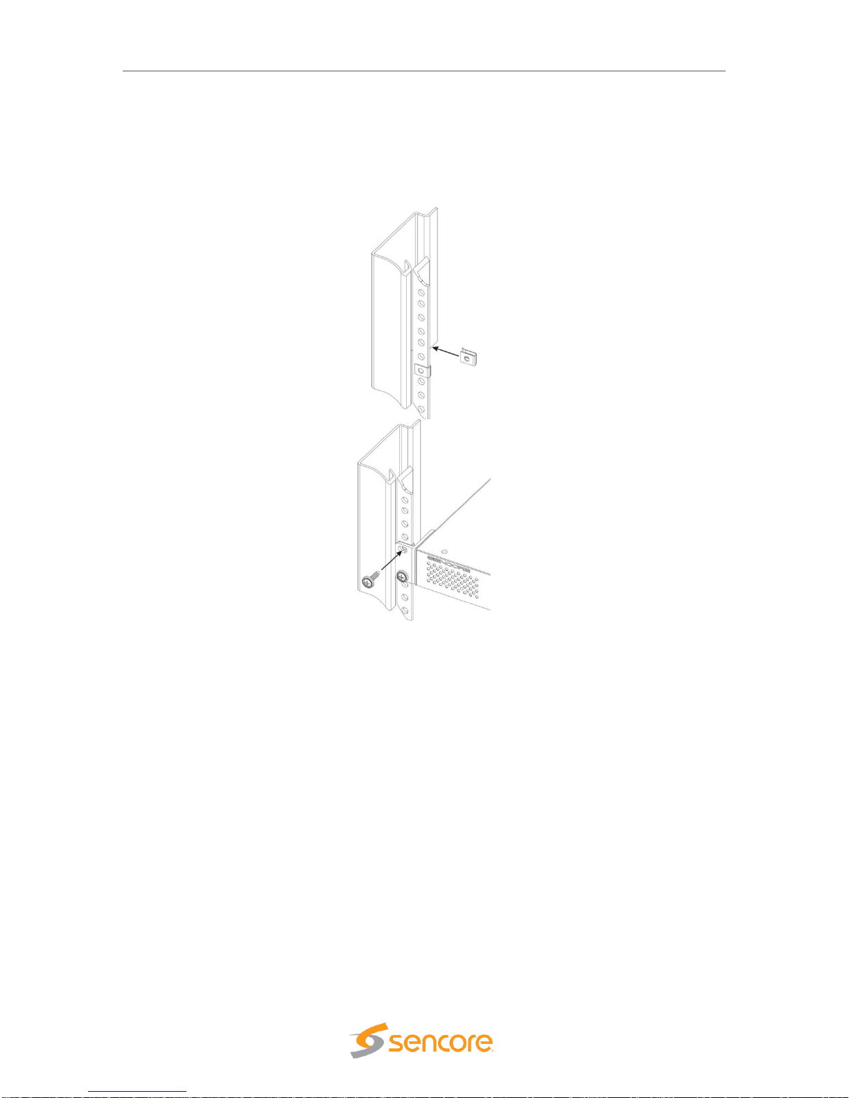
To install the MIP 6210 into a rack, use the following steps:
1. Determine the desired position in the rack for the MIP 6210 making sure that the air
intake on the front of the unit and the exhausts on the rear of the unit will not be
obstructed.
2. Insert the rack mount clips into place over the mounting holes in the rack.
3. Slide the MIP 6210 into position in the rack.
Page 11
MIP 6210 – User Manual
Page 11 (75)
4. Secure the MIP 6210 to the rack by installing the four screws through the front mounting
holes and tightening.
WARNING: To prevent injury, the apparatus must be securely attached to the floor/wall in
accordance with the installation instructions.
The MIP 6210 is designed for front-to-back ventilation. Care must be taken to ensure that this
ventilation is not impeded in any way.
Page 12
MIP 6210 – User Manual
Page 12 (75)
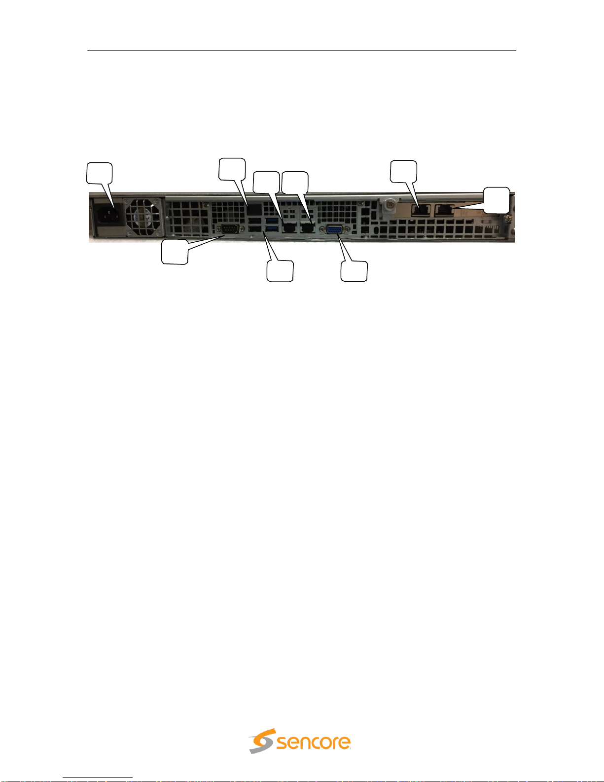
3.4 Rear Panel Connections
All of the external connections for the MIP 6210 are located on the rear of the unit. These
connections include standard computer I/O (Monitor, USB, parallel, serial, audio, and LAN ports)
and the MIP 6210 IP output connections. The power connection is also located on the rear of the
unit. The following provides an overview description of the rear panel connections and features.
Descriptions:
1. Power Connector: Provides AC power connection for powering the system
2. IPMI Port: Can be used for remote server management, but not normally used in the MIP
6210 operation
3. eth0 Port: Network port for management and streaming/recording
4. eth1 Port: Network port for management and streaming/recording
5. eth2 Port: Port available only with the addition of optional card adding either 2x RJ45 or
2x SFP ports
6. eth3 Port: Port available only with the addition of optional card adding either 2x RJ45 or
2x SFP ports
7. VGA Monitor Output
8. USB Interface Ports
9. RS-232 Port
3.5 Power Connections - Installation
Using the proper power connections is vital to the safe operation of the MIP 6210. Only use the
supplied 3-prong power connectors or those with equal specifications. NEVER tamper with or
remove the 3rd – prong grounding pin on any cord. This could cause damage to the unit,
personnel, or property.
The MIP 6210 is intended for use on either 120V or 240V systems. The power supply will
automatically detect the voltage to which it is connected. There is one power supply and one AC
power cord. To connect AC power, perform the following:
1. Locate the proper AC power cord.
2. Plug the female end of the power cord (end with no prongs) into the back of the unit.
3. Plug the male end of the power cord into a proper protected AC outlet.
6
9
8
2
354
Page 13
MIP 6210 – User Manual
Page 13 (75)
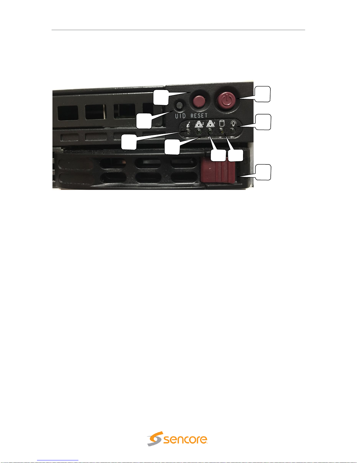
3.6 Front Panel Features
The front panel contains some pushbuttons and indicator lights. This section provides an
overview of these features.
*NOTE: Some design modifications may occur in which features shown in this image and
described below may not be found on your MIP 6210.
Front Panel Descriptions:
1. UID: Pushbutton: This pushbutton provides a unit identification light at the rear of the unit.
Press the UID pushbutton to turn on a blue light at the rear of the unit. This makes it easy
to identify the unit when viewing from the back of the equipment rack. The “i “ light on the
front panel (#8) indicates when the UID is switched on.
2. Reset Pushbutton: This pushbutton provides a reset of the system. Press and release to
initiate a reset operation of the operating system.
3. Power Pushbutton: Turns the unit AC power on and off. Hold down for 3 seconds and
release to power the unit on or off.
4. Power Light: Indicates when the unit is powered on for normal operation
5. Hard Disc Drive Light: Indicates normal OS unit disc drive activity
6. Media Drive Indicator Light: Indicates normal unit drive activity
7. Media Drive Indicator Light: Indicates normal unit drive activity
8. i Indicator Light: This light provides an indication when the UID feature is turned on
illuminating a blue light at the rear of the unit.
3
9
8
2
1
4
Page 14

MIP 6210 – User Manual
Page 14 (75)
3.7 Obtaining the MIP 6210 IP Address
Operating the MIP 6210 depends on gaining access to the unit’s network GUI as there is no front
panel interface. Connecting to the unit’s web GUI using a web browser requires knowledge of the
IP address of the port in which to enter into the address field of a web browser. To acquire and or
to change the port’s IP address from the factory default requires viewing a computer monitor
connected to the unit along with the use of a keypad to navigate the provided menus.
To obtain or make changes to the port’s IP address:
1. Connect a computer monitor to the VGA
connector and power it on. Reference Section
3.4 in this manual – (#7) rear panel port.
2. Connect a PC keyboard (USB type) to the rear
panel USB connectors. Reference Section 3.4 in
this manual – (#8) rear panel USB connection
ports.
3. With power properly connected to the MIP 6210, push and release the front panel power
button. Allow some time for boot up. The system
starts up with no user or password entry required.
A Main Menu screen appears on the monitor
.
4. The Ethernet port 0 (eth0) and Ethernet port 1
(eth1) IP addresses are shown on the initial Main
Menu. Enter the IP address of the port you are
using into your web browser. See the next sections
(3.7, 3.8) of this manual for more details on
changing the IP address and using the web GUI.
5. If the IP addresses are not shown, press the ENTER key on the keyboard to advance to
the next menu. Press the Up or Down arrow keys on the keyboard to select the eth1 or
eth0 Adapter Status listing by Moving the cursor in
front of the selection. Note: If no cursor is seen, press
ENTER a second time.
6. Press Enter on the keyboard to advance to the
configuration menu if you wish to change the IP
mode (static or DHCP) or to change IP Address,
Subnet, or Gateway addresses. See the next
section in this manual for additional information.
In some instances, you may be able to use the factory default IP addresses to gain web access.
The following default IP addresses are used.
Factory Default Settings:
eth0: DHCP
eth1: 10.0.0.61
eth2: 10.0.0.62 (with added optional ports)
Page 15

MIP 6210 – User Manual
Page 15 (75)
3.8 Unit Networking and DNS Configuration
The MIP 6210 network configuration is managed with setup menus visible by connecting a
computer monitor and USB keypad to the system. The configuration menus provide entry of host
names, gateway and DNS server addresses. Setup of the unit’s Ethernet ports including if they
are static or DHCP configured. If static, entry of the ports IP address, gateway and subnet may be
entered. This section shows the typical setup menu features and describes how to setup the
network settings.
Viewing the setup utility screens provided by the MIP 6210 requires connecting a computer
monitor to the VGA video output connector on the rear of the unit. It requires the use of an USB
keypad. View the monitor screen and use the keypad for navigation and entry. The following
navigation and entry rules are used and included as a reminder on each setup screen.
Press [Enter] to confirm a selection – advance to next menu/selection
Press [Esc] to go back to previous menu and accept entries
Press [Left] and [Right] arrow keys to navigate
Press [Up] and [Down] arrow keys to navigate
Press number and letter keys for field input values
Press [Del] and [Backspace] as needed for text entry
Configure Networks Settings
Network configuration settings are available to enter a unit host name, define a gateway and
enter primary & secondary DNS addresses. These selections are available in the “Configuration
Networks” menu.
1. From the opening menu – press the ENTER key.
2. Position the cursor in front of Configure Networks selection as in illustration below. Press
the ENTER key to advance to the Network Configuration Menu.
3. To enter a Host Name: Position the cursor in front of the Host Name row using the up
and down arrow keys. Press ENTER. The first field is selected for letter or number entry.
Enter the number or letter. Press left or right arrow key to move to the next digit. Press
ENTER key.
4. To enter a Default Gateway: Position the cursor in front of the Default Gateway row.
Press Enter. Enter the desired gateway. Press ENTER.
5. To enter a Primary and/or Secondary DNS: Position the cursor in front of the Primary
DNS and/or Secondary DNS row to be changed or entered. Press the ENTER key. Enter
the address using number keys while navigating with the arrow keys. Press ENTER.
Page 16

MIP 6210 – User Manual
Page 16 (75)
Ethernet 0 and Ethernet 1 Port Configuration Changes
Network configuration settings are available to enter a static IP address, gateway address and
subnet mask for Ethernet port 0 (eth0) and Ethernet port 1 (eth1). These selections are available
in the respective “eth1 Adapter Status” menu and “eth0 Adapter Status” menus. The following
describes the steps to enter or change a port’s static IP address.
1. From the start menu, press the ENTER key to advance to the Unit Networking screen.
2. Press the Up or Down arrow key as needed to move the cursor position in front of the
eth0 or eth1 row. Press the Enter key to advance to the Adapter eth Status menu.
3. Use the up and down arrow keys to position the cursor in front of the IP Mode row. If it
shows DHCP - Press the ENTER key to select the setting field. Click the up or down
arrow key to increment setting to “Static.” Press ENTER.
4. Use the up and down key to position the cursor in front of the IP Mode row. Press
ENTER to enter the field. Enter number values to define the desired static IP address.
Use the left and right arrow keys to move to different digits. Press ENTER when
complete.
5. Change Mask and Gateway settings using the same technique as in step 4. Press the
ENTER key when finished to accept entries and return to the menu.
Page 17
MIP 6210 – User Manual
Page 17 (75)
3.9 Controlling the MIP 6210 Using the Web GUI
Controlling the MIP 6210 is done by a network connection to either the eth0 or eth1 ports and the
use of the web interface or GUI. From any PC that is connected to the same network as the MIP
6210, open a web browser application and type the IP address of the unit in the address field.
You must obtain the unit IP address with the procedure in the Startup section.
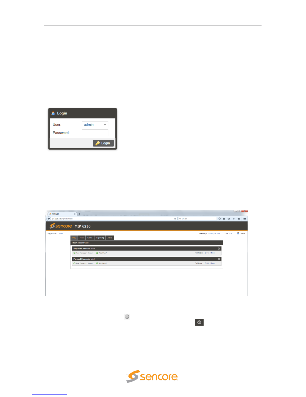
When connecting to the web GUI, you are greeted with a Login screen as shown below. The
default user field entry is admin and the default password field is left blank or no entry. Press the
login button in order to login to the web interface. The User and Password can be changed for
improved security in the Admin section of the GUI. Please see section 5.2.
When connected you are greeted with the home or start page of the web GUI as shown below.
Depending on the options and licensing some variations in the screen may be seen.
To open the MIP 6210 web interface, use one of the following supported browsers.
• Internet Explorer version 9 or newer
• Firefox
• Google Chrome
• Microsoft Edge
The user is capable of configuring parameters from this page by clicking on the selection tabs at
the top of the page below the Sencore MIP 6210 header. User configuration changes are offered
in each section by clicking on the (cog) which represents a settings configuration is
available for the listed item. Each section contains a dropdown icon which is used to
collapse or expand a section to see additional details. Further details of the common fields in the
web GUI of the MIP 6210 are described
Page 18

MIP 6210 – User Manual
Page 18 (75)
The top section or fields of the MIP 6210 web GUI includes login and operational information of
the system. Below is a reference to the fields and information provided.
1. Logged in as: This field indicates the logged in user. This field may not be selected or
changed. The User and Password may be set in the Admin tab. See section 6.1.
2. Selection Tabs: Provides operational control of the MIP 6210. Click on a tab to select.
3. Storage Disk Usage: Indicates actual disk size that is currently in use
4. Storage Disk Usage: Indicates total disk size available for use
5. CPU: Indicates the percentage of CPU usage
6. Logout: Provides quick logout, click to log out from the MIP GUI.
Field
Button/Selections
Description
1. Logged in
as:
Admin (Default)
Shows the logged in user name. A view only field.
2. Selection
Tabs
Play
Record
Files
Admin
Reporting
About
Provides control for playing stream and PCAP files
Provides control for recording streams and PCAP
files (Optional)
Provides viewing of media disc play files
Provides administrative tasks
Provides reporting and logging
Provides unit information
3. Disk
Usage
Example shown: 6.6
GB
Indicates the disc drive memory space that is
currently being used by the system
4. Disk
Usage
Example shown:
98.3GB
Indicates the total disc drive memory space
available for TS and PCAP stream storage
5. CPU
Example shown: 0%
Indicates percentage of CPU processing capacity
that is in use.
6. Logout
Click on
icon
Click to log out of the web GUI connection to the
MIP 6210
34561
2
Page 19
MIP 6210 – User Manual
Page 19 (75)
3.10 Simplified Startup - Getting a Stream Playing
This section provides a quick start process to assist you in getting an output stream playing to the
Ethernet 1 port. This section provides only enough information to get you outputting a TS stream.
It is not intended to completely summarize all the information contained in this manual. Please
reference other portions of the manual to answer questions and become familiar with the MIP
6210 and its features.
Get Unit Powered & Network Connected:
1. Locate the MIP 6210 in a convenient location or mount in an equipment rack in which AC
power and a connection to the network is closely available. Connect an AC cord from the
rear of the unit to the AC outlet.
2. Connect a network cable between the Ethernet port 1 (Port nearest the VGA video
connector on rear panel) and to your network.
3. Momentarily press the Power button on the unit front panel. You will observe and hear
normal PC startup activities. The front panel power light should illuminate and drive light
activity indicated. Wait while the unit boots up.
Establishing a Web Connection with the Pre-Set Management IP Address
To access the MIP 6210 web user interface, it is necessary to establish an Ethernet connection to
the device. There are two alternative ways to connect to the MIP 6210’s management IP address:
1.) Use the pre-set management IP address or 2.) Connect a monitor and keyboard to the server
to retrieve the IP address. The following steps describe how to use a pre-set management IP
address on a PC via a connection to the Eth1 port.
The MIP 6210 is shipped with the following factory settings for the Eth1 network ports.
Eth1 Default IP address:
10.0.0.61
You can connect to the web UI
of the MIP 6210 using a PC and
connecting directly from the
PC’s network port to the Eth1
port with an Ethernet cable.
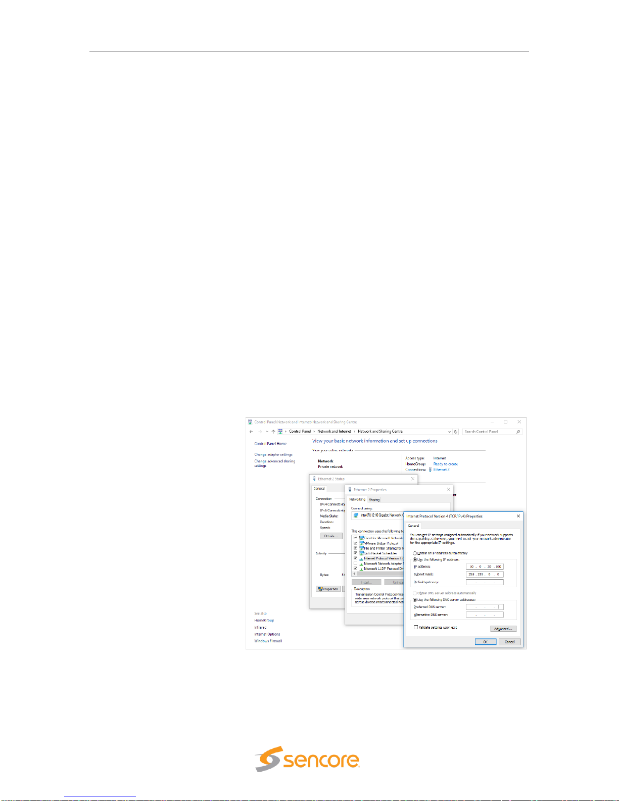
Configure the PC’s network port
settings to permit a direct
connection.
For Windows, the network
parameters are set in the
Control Panel — Network and
Internet — Network and
Sharing Center — Network
Connection — Properties —
Internet Protocol Version 4
Properties viewing menu.
Select the user defined address, and set the PC’s IP address to 10.0.0.60 and the subnet mask
to 255.255.0.0.
When the IP address of the PC has been set in the same subnet as the MIP 6210’s factory
setting, a web browser can be used to access the web user interface at 10.0.0.61.
Page 20
MIP 6210 – User Manual
Page 20 (75)
Retrieve and/or Configure the Unit IP address
You can determine the MIP 6210’s IP address of both Eth0 and Eth1 ports by connecting a
monitor and keyboard to the server. All configuration of the MIP 6210 is done via a PC and web.
The Ethernet port 1 can serve both as a management port for web browser access and as the
streamer IP/PCAP network port. The following section describes how to connect a monitor and
keyboard to the server to retrieve and/or change the unit’s IP address on both ports. To connect
to the unit’s web browser:
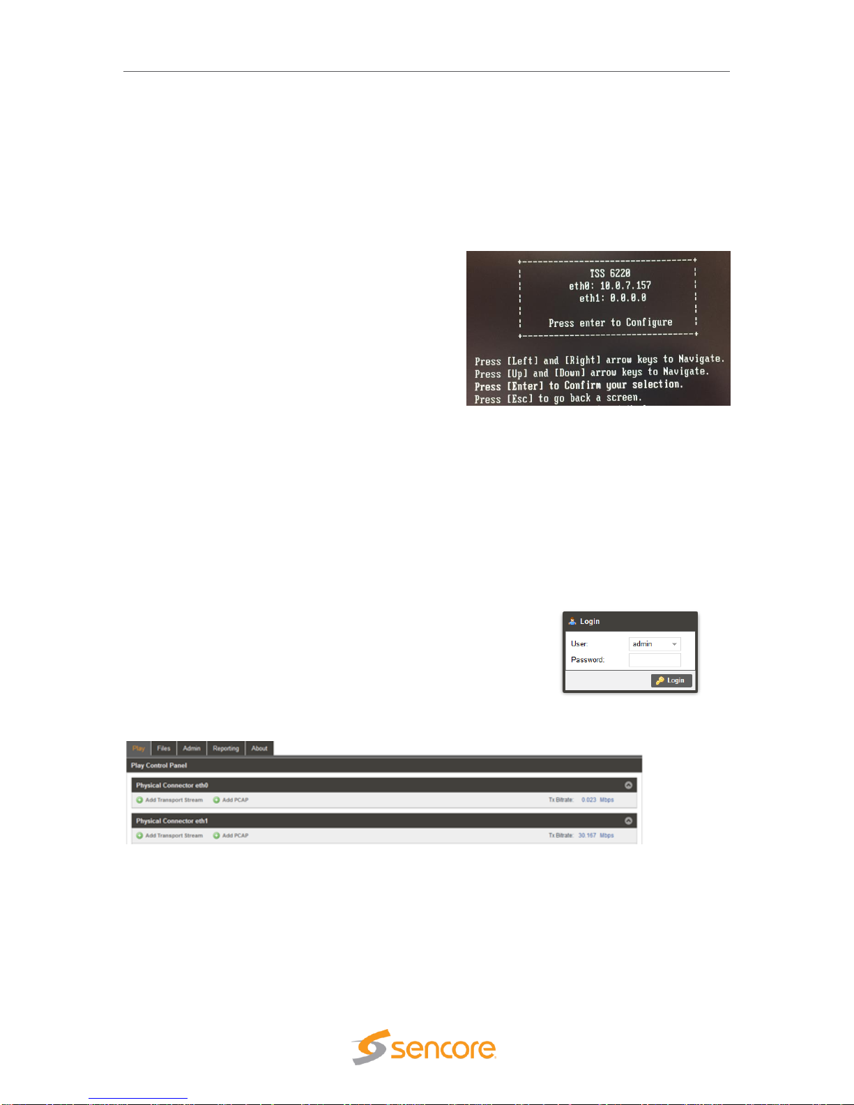
1. Connect a computer monitor to the MIP
6210. Connect a VGA video cable from the
VGA connector at the rear of the MIP 6210
to the computer monitor. Power up the
computer monitor. Connect a PC USB
keyboard to one of the USB ports at the rear
of the MIP 6210. The display screen on the
monitor will indicate the current IP address
for the Ethernet 1 port (eth1). It also shows
the IP address for the other Ethernet 0 port
(eth0)
2. If you do not have a computer monitor you may try to access the web GUI as described
in the previous page using the factory default IP settings shown below:
Ethernet port 0 (eth0): 10.0.0.61
Ethernet port 1 (eth1): 10.0.0.62
Use PC Web Browser to Connect to the MIP 6210’s Web GUI
1. Connect a PC to the same network as the MIP 6210. Open a web browser application on
the PC and in the top address field enter the IP address of the eth1 port as found in the
previous step.
2. The Login screen appears with a successful connection.
The default User name is admin and the default password
is blank or no entry. Click on the Login field.
When successfully logged in the web connection to the GUI
produces a Play Control Panel. Click on the Play tap to access.
Use FTP or SMB to Load Stream/PCAP Files to Media Storage Drives
The MIP 6210’s media drives are available to store files used for playout in a schedule. Click on
the “Files” tab at the top of the GUI to view available files. If a file is available for selection, click
on the Schedule tab and skip to the instructions “Creating a Play/Event Schedule” instruction
section.
Page 21
MIP 6210 – User Manual
Page 21 (75)
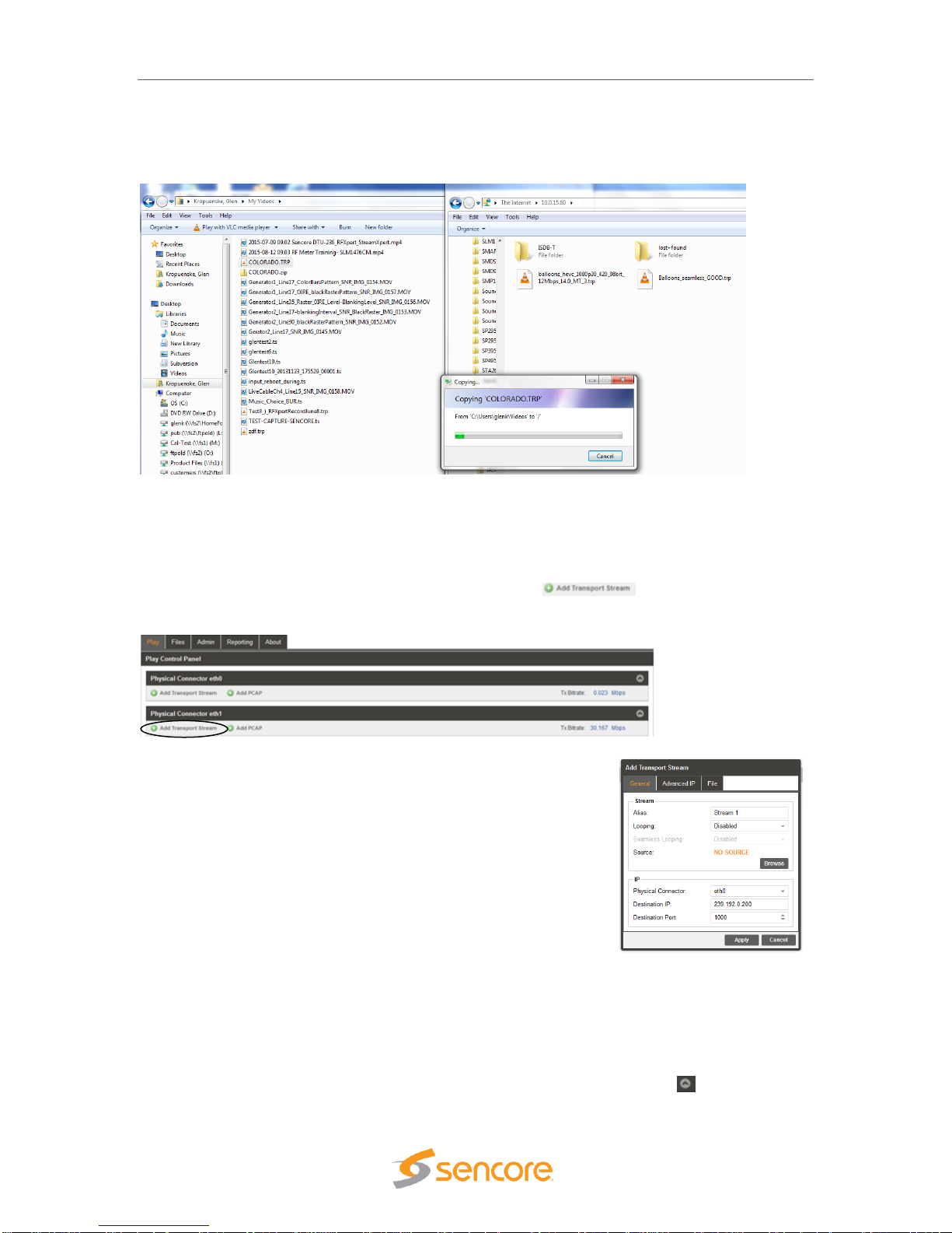
If no files are available you will need to access and use FTP or SMB to load files to the media
drive. Read on in this section for details on accessing FTP and loading files/folders. Using FTP
requires starting an instance of Windows Explorer on your PC and entering the address of the
FTP server. Follow the instructions below.
The FTP server address is located in the
File Viewing Panel (Files tab) in the MIP
6210’s web GUI. Look near the top of the
page under the Files Control Panel
header. (See circle in illustration) Click at
the end of the field and drag the mouse to
highlight the ftp address. Copy the
address – (Keyboard Ctrl C key
sequence).
Open a Windows Explorer application window on your PC. In the header of this application – paste
in the ftp address listed in the TSS 6220’s File menu
on the second line below the Files Control Panel
heading. Paste the ftp address – (Ctrl-V) as shown
in the example figure.
Example shown: ftp://10.0.15.60.
Press the Enter key on your keyboard.
Upon connection to the ftp server you will be prompted for a
username and password: Below is the default User and
Password. The Username/Password can be set - see section 5.2 for
instructions.
User: root
Password:
Note: The Password field is left blank or no entry as shown.
Click on the Log On field to access the FTP server.
Upon connection to the ftp
server you can view the
current folders and play
files in the TSS 6220.
To transfer files to the ftp
server, you may use
common window’s based
file copy and paste
techniques or drag and
drop techniques. For example, open a 2nd version of Windows Explorer application. (Right mouse
click on the Windows Explorer icon at the bottom system tray – click on Windows Explorer) You
now have both the FTP server window and the Windows Explorer application running. Position
Page 22
MIP 6210 – User Manual
Page 22 (75)
both the FTP window and the Windows Explorer windows beside each other on your PC screen.
See example below. Click on a file or folder in the Windows Explorer window and drag it into the
right side of the FTP server window. The folder or file is transferred as illustrated below.
In Play Control Panel Add a Transport Stream
The MIP 6210 web GUI opens to the Play Control Panel (Play Tab). To create or add a playing
stream to the IP output on the Ethernet 1 port, click on the icon below the Physical
Connector eth1 heading. An Add Transport Stream menu opens and defaults to the General tab.
Configure the Output Stream
The General configuration menu provides selections defining the
output IP stream and IP destination address and ports. Select a
source file for playout. Click on the Browse field and navigate to the
file you wish to select for playout. Open the file. It will populate the
Source listing with your file name.
Define the IP parameters. The Physical Connector field should
indicate eth1. If not, select the dropdown and select eth1. Click on
the Destination IP field and enter the destination address. Enter a
Destination Port in the Destination Port field. Click on the Apply box
at the bottom of the menu to add the stream to the Ethernet port 1 (eth1) output.
Start the Output Stream Playing
After the stream is added you will see the stream listed in the Physical Connector eth1 section of
the Play Control Panel. If you don’t see the listing click on the Show/Hide icon . Click on the
Page 23

MIP 6210 – User Manual
Page 23 (75)
Play icon to begin producing the stream output. The light at the far right turns green and the bit
rate field beside it begins to show the output transport stream bitrate. The stream time begins to
increment and the blue highlight advances from the left (start) to the right (end) in the center
progress window.
Your selected stream is now outputting to the network. Click on the cog wheel icon to make
changes to the stream output configuration. You may also click on the icon to bring up a
configuration and monitoring panel. It provides a shortcut to improve viewing and playout
statistics while offering some convenient control options.
Page 24

January 2018
Form 8166A www.sencore.com | 1.605.978.4600 Revision 1.2
4 Play Control Panel
The Play Control panel is selected by default upon entering the web GUI with the correct user
and password criteria. This panel may also be selected at any time by clicking on the Play tab in
the GUI header. The Play Control panel provides management of all the TS files and PCAP files
that are configured for playout from the MIP 6210. This panel manages each of the available
Ethernet streaming ports defining which TS streams and PCAP files are sourced to each port.
This panel further defines the criteria of each of the streams and PCAPs added to the output. This
section provides an overview of this panel and its features. Subsequent sections provide further
details of some of the menus within these sections.
4.1 Play Control Panel Overview
The Play Control Panel includes a section for each available ethernet output port. The sections
are identified by headers indicating the physical connector port. For example, the ethernet port 0
is shown as “Physical Connector eth0.” If you have added the optional Ethernet ports to the MIP
6210, then two additional sections are included for Physical Connector eth2 and eth3.
Each Ethernet port section includes some common control fields. The following is a general
overview of items in the Play Control Panel and description of some common fields.
Item or Field
Button/Action
Description
A. Add an IP
Transport
Stream
Output
Click on this
icon to add a TS file
to stream to the
output
Provides menu to select a file and define stream
output characteristics adding the output to the
Ethernet port. See section 4.3. for details
B. Add PCAP
stream output
Click on this
icon to add a PCAP
to the output
Provides a menu to select a PCAP file and criteria to
define it adding it to the Ethernet output port 0. See
section 4.4 for details
C. Show/Hide
port info
Selectable, click on
the icon
Hides all the stream and PCAP listings, click to hide or
click to show all streams/PCAPs
D. TX Bitrate
Not a selectable field
Shows the total output bitrate of all the streams and
PCAP to the Ethernet port
E. TS Stream
See next section
Row defining a stream output to Ethernet 1 port (eth1)
C
E
F
D
Page 25

MIP 6210 – User Manual
Page 25 (75)
F. PCAP stream
See next section
Row defining a PCAP output to the Ethernet 1 port
4.2 Stream/PCAP Information Overview
The Play Control Panel shows all the playout IP streams and PCAPs. Each playback transport
stream and PCAP file output has a row of information and control functions. There are common
data fields for each stream/PCAP forming columns of information in the panel. This section
provides a brief definition of the information provided in each column.
Item or Field Name
Button/Action
Description
A. Status &
Configuration
Click on this icon
Provides a window showing IP stream/PCAP status
and configuration information
B. Configuration
Menu Select
Click on this icon
to access
configuration menu
Provides a menu with configuration settings to define
the output IP/PCAP stream and IP address
C. Output
Control
Pause -click on
icon to Pause
Play – click on
icon to start output
Indicates IP/PCAP stream as playing or paused. Click
on icon to pause or play. When paused, the current
location of the stream or PCAP is maintained.
D. Stop Control
Click on icon to
stop IP/PCAP output
Stops a playing or looping IP/PCAP output. Click on
play icon to restart – restarts at file starting point.
E. Stream name
or alias
Not selectable, No
action
Shows a default output IP/PCAP stream name. See
section 4.3.1 for entering an optional alias name.
F. TS/PCAP File
name
Double click to
browse/select
different file
Indicates the current selected play file.
G. Stream
configuration
Click on icon to
open configuration
menu
Provides convenient overview of stream playout
status, some critical settings, and provides some
control features. See section 4.6 for details.
H. Play Status
Not selectable
Indicates a stream is playing or active. Indicates play
position/time within the start-to-end duration time
span. Visual blue highlight indicates stream progress.
K
I
H
L
G
M
E
A
B
C
D
Page 26

MIP 6210 – User Manual
Page 26 (75)
I. IP
Address/Port
Not selectable
Indicates the destination IP address and port
J. Delete icon
Click to delete
stream or PCAP
Removes a IP/PCAP stream from the play listings and
Ethernet output
K. Total Port
Bitrate
Indication
Not selectable, view
only
Indicates accumulative Ethernet port bitrate of the
addition of all playing TS streams and PCAP files
L. Bitrate
Indication
Not selectable, view
only
Indicates bitrate of the individual stream to the Ethernet
port
M. Status
Indicator
Not selectable, view
only
Indicates status of output:
Gray: Inactive – stopped or paused
Green: Good playback output condition
Red: Fault condition -
4.3 Player - Adding a Transport Stream
To create a new IP stream output requires that you select a play file and define its output
parameters. To create or add a playing stream, click on the icon. Note that this
selection is available for each of the Physical Connector Ethernet ports of your MIP 6210. Select
the icon in the section corresponding to the Ethernet port in which you want the
output to stream.
The Play Control Panel is simplified for viewing with a Hide/Show streams feature for each
Physical Connector eth section. To show all the streams outputting to an Ethernet port click on
the Show/Hide icon .
Page 27

MIP 6210 – User Manual
Page 27 (75)
4.3.1 Add Transport Stream - General Configuration
Upon clicking on the icon, the Add
Transport Stream menu opens. This menu contains 3
selection tabs which provide menus for defining the
transport IP stream. By default, the General tab is
selected providing some common selections to configure
the output. The General configuration menu provides
selections defining the output IP stream and IP
destination address and ports. This section provides an
overview of the configuration fields.
The first step is to select a source file for playout. Click
on the Browse field and navigate to the file you wish to
select for playout. Select the file and open it. It will
populate the Source listing with your file name. In the
Stream section of the click on the Alias field and enter an
alias name if desired. This is not required as the
application automatically assigns a name as an incrementing stream number.
If you want the playing stream upon reaching the ending point to loop back to the start and
continue playing out, click on the dropdown arrow in the Looping field. Select “Enabled” if you
want the looping feature active. When looping is enabled, the Seamless Looping field becomes
available to configure. Set this field to “Enabled” if you want the MIP 6210 to properly seem
together the ending point with the beginning point of the stream. With this enabled the MIP 6210
corrects PCR discontinuities and continuity counters.
Define the IP parameters in the IP section. Verify that the Physical Connector field indicates the
desired Ethernet port. If not, select the Ethernet port you wish to output the stream. Enter the
Destination IP and the Destination Port values. Click on the Destination IP field and enter the
destination address. Click on the Destination Port field and enter a Destination Port. Click on the
Apply box to add the stream to the Playout Control Panel under the respective Ethernet port.
Add Transport Stream – General Tab Settings
Setting
Range
Description
Stream - Alias
Value and or Letter
Entry
Provides entry to name or assign alias to identify
a stream. If no name is entered, the MIP 6210
assigns an incrementing stream number
Stream - Looping
Enabled
Disabled
Turns on the looping function in which the file
plays to the end and then loops back and starts
playing from the start again. When disabled, the
stream stops when it reaches the end of the file
Seamless
Looping
Enabled
Disabled
Enabled: Provides corrections to PCR values and
PAT/PMT table continuity counts so as to appear
to the receiver as a continuous uninterrupted
stream.
Source
Not selectable
Indicates “No Source” when no file has been
selected. Indicates the selected file name when a
file is opened.
Page 28

MIP 6210 – User Manual
Page 28 (75)
Browse
Click on field to
access stream files in
library
Provides navigation to browse to available stream
and PCAP files for selection.
IP – Physical
Connector
Selects eth0 or eth1,
the standard
Ethernet ports,
eth2 and eth3
available if MIP 6210
has added optional
ports
Entry selects which of the available Ethernet
ports on the MIP 6210 that the stream output is
assigned
Destination IP
224.0.0.0 –
239.255.255.255
This address is the IP address the source device
is sending to for a multi-cast. A unicast would use
an IP address less than 224.0.0.0.
Destination Port
0 – 65535
This is the UDP port the source device is sending
to.
4.3.2 Add Transport Stream - Advanced IP Configuration
The Add Transport Stream Advanced IP tab includes settings to define the MIP 6210 as a
specific source device for IGMPv3. This feature allows each steam to be seen by the network as
a unique source device with a unique IP address, and/or source port, and/or MAC address. This
section provides descriptions of the settings in the Advanced IP menu.
Page 29

MIP 6210 – User Manual
Page 29 (75)
Setting
Range
Description
Source IP Mode
Settings: Select Auto
or Manual
In Auto, the MIP 6210 simulates a source device
and creates and communicates a unique source
IP address. In Manual, a user entered source IP
address can be entered.
Source IP
Available for entry
when Source IP
Mode is set to
Manual.
Provides entry of a Source IP address for the
stream that is communicated by the MIP 6210
Source Port
Click up or down
arrows to increment
value shown. Click in
field and enter value.
Range: 1030 to
65535
Specifies a value for the source port associated
with the stream.
Source MAC
Mode
Auto,
Manual
In Auto, the MIP 6210 simulates a source device
and creates and communicates a unique source
MAC address for the stream. In Manual, a user
Source MAC address can be entered.
Source MAC
In “Manual Mode”
enter MAC address,
Provides entry of a MAC address you want to
specify as the Source MAC for the stream
TS Packets Per
IP Packet
Enter value 1 to 7,
Default is 7
This setting determines the number of TS stream
packets that are inserted into IP packets. 7 being
the maximum and the typical setting. Lesser
packets may be selected.
4.3.3 Add Transport Stream - File Configuration
The File tab within the Add Transport Stream menu provides
selection to define starting and ending points when playing out
an IP stream file. It further provides a selection to
automatically or manually control the output IP stream bitrate.
To access this configuration menu, click on the File header
tab
You can enter starting and ending times within the play
duration time of the IP play file. You can enable or disable the
playout to conform to these entered start point and end point
times. Set the Start/End Point field to “Enabled” and enter the
Start Point and End Point.
The Bitrate Mode provides an automatic setting in which the
MIP 6210 automatically determines the ideal playout stream rate. You can set the Bitrate mode to
Manual when you wish to increase the output bitrate. In the manual mode, click on the up and/or
down arrows in the bitrate field to increase or decrease the bitrate in Mbps.
The following chart provides an overview of the configuration settings in the File menu.
Page 30

MIP 6210 – User Manual
Page 30 (75)
Setting
Range
Description
Start/End Points
Enabled
Disabled
Adds control of the output defining a starting and
stopping point within the play duration of the
selected stream or PCAP play file
Start Point
Range of play file
duration but prior to
End Point
This setting establishes a point/time in the play
file duration which defines the starting point of the
stream or PCAP file when it is streaming to the
output port
End Point
Range of play file
duration but after the
start point
This setting establishes a point/time in the play
file duration which defines the ending point of the
stream or PCAP file when it is streaming to the
output port
Bitrate Mode
Auto
Manual
In Auto the MIP 6210 determines the playout rate
automatically. In Manual, the user may modify or
enter a playout bitrate.
Bitrate (Manual)
Enter Bitrate
Provides user entry to manually enter a desired
output bitrate
The Bitrate Mode provides an automatic setting in which the MIP
6210 automatically determines the ideal playout stream rate. You
can set the Bitrate Mode to Manual to increase the output bitrate. In
the manual mode, click on the up and/or down arrows in the bitrate
field to select from available bitrates in Mbps. The following chart
provides an overview of the configuration settings in the File menu.
4.4 Adding a PCAP Play File
To create a new PCAP output file test stream requires that you select a PCAP file and define its
output parameters. To create or add a PCAP stream, click on the icon. Note that this
selection is available for each of the Physical Connector Ethernet ports of your MIP 6210. Select
the icon in the section corresponding to the Ethernet port in which you want the output
to stream. This section describes how to select, add and configure a PCAP file to playout one of
the MIP 6210’s Ethernet port outputs.
The Play Control Panel is simplified for viewing with a Hide/Show streams feature for each
Physical Connector eth section. To show all the streams outputting to an Ethernet port click on
the Show/Hide icon .
Page 31

MIP 6210 – User Manual
Page 31 (75)
4.4.1 Add PCAP - General PCAP Play Settings
When adding a PCAP file to play on the MIP 6210 use the configuration settings in the General,
Advanced PCAP, and File tabs to configure the output.
Click on the icon to add a PCAP file to the play list. Upon clicking the icon, the Add
Transport Stream menu opens. This menu contains 3 selection tabs which provide menus for
defining the transport PCAP stream. By default, the General tab is selected providing some
common selections to configure the output. The General configuration menu provides selections
defining the output PCAP stream and its destination address and ports. This section provides an
overview of the configuration fields.
The first step is to select a source PCAP file for playout. Click on the Browse field and navigate to
the PCAP file you wish to select for playout. Select the file and open it. It will populate the Source
listing with the file name. In the Stream section of the menu click in the Alias field and enter an
alias name as desired. This is not required as the application automatically assigns a name as an
incrementing stream number.
If you want the playing PCAP stream upon reaching the ending point to loop back to the start and
continue playing out, click on the dropdown arrow in
the Looping field. Select “Enabled” if you want the
looping feature active.
Define the PCAP parameters in the PCAP section.
Verify that the Physical Connector field indicates the
desired Ethernet port. If not, select the Ethernet port
you wish to output the stream. Enter the Destination
IP and the Destination Port values.
The PCAP file contains within it the destination and
port addresses so these parameters cannot be
entered in the same manner as with a TS stream.
When finished with the configuration, click on the
Apply box to add the stream to the Playout Control
Panel under the respective Ethernet port.
Page 32

MIP 6210 – User Manual
Page 32 (75)
Setting
Range
Description
Stream - Alias
Value and or Letter
Entry
Enter name you want to identify stream. If no
name is entered, the MIP 6210 assigns an
incrementing stream number
Looping
Enabled
Disabled
Enabled: Turns on the looping function in which
the PCAP file plays to the end and then loops
back and starts playing from the start again.
Disabled: After the file is started it plays to the
end of the file and stops.
Source
Not selectable
Indicates “No Source” when no file has been
selected. Indicates the selected file name when a
file is opened.
Browse
Click on field to
access PCAP files in
library
Provides navigation to browse to available PCAP
files for selection.
IP – Physical
Connector
Selects eth0 or eth1,
the standard
Ethernet ports,
eth2 and eth3
available if MIP 6210
has added optional
ports
Entry selects which of the available Ethernet ports
on the MIP 6210 that the PCAP output is
assigned
4.4.2 Add PCAP - Advanced PCAP Settings
The Advanced PCAP selection tab provides a menu to define
the Source MAC Mode. The MAC address indicated by the
PCAP play output may be configured to match the MAC
address of the NIC or be IP Source criteria. The following
provides descriptions of the settings included.
Source MAC Mode: From NIC
When the MAC address source is set to “From NIC” the MAC address for all the Ethernet frames
transmitted during PCAP play output shall be the same as the MAC address of the selected
output NIC.
Source MAC Mode: From Source
When the MAC address source is set to “From Source” the MAC address for all Ethernet frames
transmitted during a PCAP play output shall be the same as captured in the selected PCAP file.
Page 33

MIP 6210 – User Manual
Page 33 (75)
Setting
Range
Description
Source MAC
Mode
From NIC
From Source
Determines the MAC address transmitted with all
Ethernet frames during PCAP output.
From NIC: MAC is the same as MAC of selected
NIC
From Source: MAC address is the same as MAC
captured in the selected PCAP file.
4.4.3 Add PCAP - File Play Settings
The File tab within the Add PCAP menu provides selection
to define starting and ending points when playing out a
PCAP file. You can enter starting and ending times within
the play duration time of the PCAP file. You can enable or
disable the playout to conform to these entered start point
and end point times that you specified. To access this
configuration menu, click on the File header tab. The
following section provides an overview of this menu.
Keep in mind some general rules. You cannot set an End
Point time that is after the normal End Play time of the
selected file. You cannot set an End Point that is prior to the Start Point time. You can set a Start
Point and End Point in the File Menu, but you must set the Start/End Points to “Enabled” to
playout only the part of the PCAP specified by the Start/End Point times.
Setting
Range
Description
Start/End Points
Enabled
Disabled
Adds control of the output defining a starting and
stopping point within the play duration of the
selected stream or PCAP play file
Enabled: Directs output to follow the defined start
and ending time references entered
Disabled: Output PCAP does not follow start or
ending time entries. Playout is from the beginning
of the file to the end of the file
Start Point
Range of play file
duration but prior to
End Point
This setting establishes a point/time in the play
file duration which defines the starting point of the
stream or PCAP file when it is streaming to the
output port
End Point
Range of play file
duration but after the
start point
This setting establishes a point/time in the play
file duration which defines the ending point of the
stream or PCAP file when it is streaming to the
output port
To setup starting and ending playback points for a PCAP file. Note the duration of the file in the
Play Control Panel prior to specifying the starting and ending points as the times selected must
be within the duration offered by the file.
Page 34

MIP 6210 – User Manual
Page 34 (75)
Select the cog wheel for the PCAP file to be specified. Click
on the File tab to select the File Menu containing the starting
and end points settings. Click the dropdown arrow in the
Start/End Points field and select “Enabled.” The Start Point
and Ending Point fields become available for entry. Click on
the appropriate hour, minute, seconds fields and modify to the desired start time. Repeat to enter
the desired end time.
When starting and ending points are specified and enabled, the
playback windows observed in the Playback Control Panel change
to indicate the start/end limits that are specified. Brackets indicate
the starting and ending points.
4.5 IP Stream and PCAP Status & Configuration Information
For each of the IP streams or PCAP files that are listed in the Play Control Panel a Status and
Configuration window is available. To
access this window and add it to the
panel, click on the icon at the left of the
row containing the IP stream or PCAP
listing. The Status and Configuration
boxes are added to the Play Control Panel
providing status and configuration details. Click on the icon at the same location to hide the
status and configuration information.
IP Stream - Status and Configuration Windows
This section summarizes the status and configuration information provided for an IP stream.
Summary of the listings and descriptions of the Status section.
Status Listing
Description
File Size:
Indicates the total memory size of the play file
Duration:
Indicates the total playtime or duration of the selected file or
PCAP
Source IP:
Indicates the source IP address
Page 35

MIP 6210 – User Manual
Page 35 (75)
Source MAC:
Indicates the source MAC address
Mode:
Indicates the current streaming Mode, Multicast, Unicast,
Receiver MAC:
Indicates the MAC address of the receiver, when available or
communicated by the receiver
Summary of the listings and descriptions of the Configuration section.
Configuration Listing
Description
Playback Loop:
Indicates the Playback Loop setting as Enabled or
Disabled. Indicates if the Playback Loop feature is active
for stream playout
Source IP Mode:
Indicates the Source IP Mode setting as Auto or Manual.
Auto indicates the IP automatically selected by the MIP
6210. Manual provides user entry of the source IP
address.
Source Port:
Indicates the Source Port value setting
Source MAC Mode:
Indicates the Source MAC Mode setting as Auto or
Manual. Auto indicates the MAC address is automatically
selected and communicated by the MIP 6210. Manual
provides user entry of the MAC address communicated
as the Source
TS Packets:
Indicates the number of TS packets per IP packet setting
Seamless Looping:
Indicates the Seamless Looping Setting as Enabled or
Disabled
Bitrate Mode:
Indicates the Bitrate Mode setting as Auto or Manual.
PCAP File - Status and Configuration Windows
Click on the icon at the left of the row containing a PCAP stream adds the Status and
Configuration windows to the Play Control Panel. There is less status and configuration
information for a PCAP file compared to an IP stream file. The following describes the information
provided in the Status and Configuration windows. Click on the icon at the same location to
hide the Status and Configuration windows.
Page 36

MIP 6210 – User Manual
Page 36 (75)
Status Listing
Description
File Size:
Indicates the total memory size of the PCAP file
Duration:
Indicates the total playtime or duration of the selected PCAP file
Source MAC:
Indicates the source MAC address
Configuration Listing
Description
Playback Loop:
Indicates the Playback Loop setting as Enabled or
Disabled. Indicates if the Playback Loop feature is active
for PCAP playout. When Enabled, the PCAP output upon
playing to the end of the file loops back and restarts
Source MAC Mode:
Indicates the Source MAC Mode setting as From NIC or
From Source. Setting determines the Source MAC
transmitted with Ethernet frames. From Source: MAC
address is the same as MAC captured in the selected
PCAP file.
4.6 IP and PCAP Monitor Panel
For each listed transport stream or PCAP row in the Play Control panel you will find a icon.
Clicking on this icon provides a monitoring panel for that transport stream or PCAP output. This
panel provides a convenient shortcut to improve viewing of the playout statistics and provides
several convenient control options. The following descriptions provide an overview of the
features provided.
L
D
J
H
A
ECG
I
K
F
B
Page 37

MIP 6210 – User Manual
Page 37 (75)
Configure IP/PCAP Panel Descriptions
Item or Field Name
Button/Action
Description
A. File name
Not a selectable field
Indicates the current source file for the transport
stream or PCAP file that is playing.
B. Browse
Click to browse or
view available files
Provides quick access to view files, to locate
current play file or search for files. Files cannot be
selected in this menu to replace the existing play
file.
C. Bitrate
Not selectable
Indicates the bitrate of IP or PCAP stream
D. Play location
time indicator
Not selectable
Indicates the current play position or time within
the duration or total play time of the IP or PCAP
stream
E. Stream End
Time
Not selectable
Indicates the total time duration or the ending time
of the IP or PCAP stream.
F. Play Bar
Progress
Indicator
Not selectable
Provides visual indicator that the stream output is
active and progressing. Indicates the current play
position or time relative to the start and end points.
G. Play/Pause
Control
Pause,Click on
icon to pause
output
Play – click on
icon to start output
Indicates IP/PCAP stream as playing or paused.
Click on icon to pause or play. When paused, the
current location of the stream or PCAP is
maintained.
H. Stop Control
Click on icon to
stop IP/PCAP
output
Stops a playing or looping IP/PCAP output. Click
on play icon to restart – restarts at file starting
point.
I. Loop Control
Click on icon to
enable loop mode.
Enable or Disable
Indicates the loop mode is enabled. The
stream plays to the end and loops to the starting
point and continues to play out.
Indicates the loop mode is disabled. The stream
plays to the end and stops.
J. Start Point
Time
Value cannot be
changed in this menu
Indicates a specified stream starting point time.
K. Start/End
Time Play
Enable
Click box – adds check
in box (Enabled), click
box removes check mark
(Disabled)
Provides Enable/Disable control of start/end points
of the playout stream. Enabled (Box checked)
stream plays from entered start to end points.
Disabled (box not checked) the stream plays from
beginning to end of the file
L. End Point
Time
Value cannot be
changed in this menu
Indicates a specified stream End Point time.
Page 38

MIP 6210 – User Manual
Page 38 (75)
5 File Viewing Panel
The File Viewing Panel provides a convenient reference to view the media drive folders and files.
It provides navigation to all directory levels. It provides information of each file including the
naming, type, size, bitrate and duration information. This section describes the navigation tools
and information provided.
The File Viewing Panel does not provide file or folder management. All folder and file
management functions are performed using FTP or SMB. FTP or SMB provides file loading to the
media drive, folder creation and naming. It provides file management including renaming, moving,
and deletion. The next sections in this chapter describe how to access and use FTP and SMB.
File Viewing Panel Descriptions
The File Viewing Panel is structured much like that of a PC based file viewing application. It
differs in the information provided regarding the file information providing information important to
managing the MIP 6210’s output. The following chart provides details of the fields and features of
this panel.
To view folders or files, click on the folder in the root directory. Or, you may click on the
navigational icons to move back or up in the folders directory.
Item or Field Name
Button/Action
Description
A. Back
Click back icon
Moves back one level in the directory
B. Forward
Click forward icon
Moves forward in the directory level. When
grayed out – the action is not available file
C. Up
Click Up Icon
Moves up in the directory. When grayed out
the action is not available
D. Directory
Not selectable
Shows the selected file/folder hierarchy with
left to right order
E. Refresh
Screen
Click on icon
Refreshes the page and contents
A
B HD E F
I
J
C
KLG
Page 39

MIP 6210 – User Manual
Page 39 (75)
F. Search
Folder/File
hierarchy
Enter text in the
field
Click on field – enter folder or file names to
search the directory
G. Folder/File
Directory
Not a Selectable
field
This field shows the selected file/folder
hierarchy
H. File Name
Not a Selectable
field
Indicates a list of all the files by name of in
the selected folder
I. File Type
Not a selectable
field
Indicates the type of file by suffix for each of
the files
J. File Size
Not a selectable
field
Indicates the memory size of the named file
K. File Bitrate
Not a selectable
field
Indicates the playout bitrate of the file when
added to the playlist and output from the MIP
6210
L. File
Duration
Not a selectable
field
Indicates total duration of the play file
5.1 FTP - SMB Loading Play Files to the MIP 6210
The MIP 6210 requires stream files and PCAP files to play out as scheduled events. The files
must be loaded onto the internal storage drives of the unit. This is done using FTP (File Transfer
Protocol), a common protocol used for the transfer of computer files between a client and server
on a network. Or, you may use Samba (SMB), a network file sharing protocol implemented in
windows.
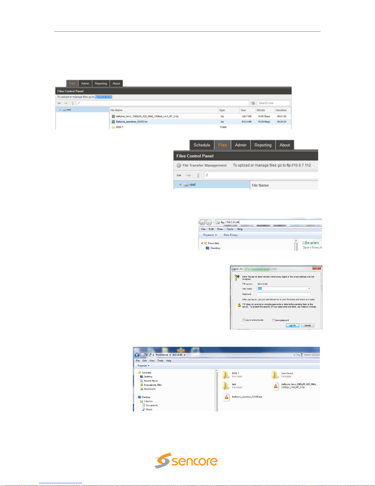
The FTP server address is located in the File
Viewing Panel (Files tab) in the MIP 6210’s web GUI.
Look near the top of the page under the Files Control
Panel header. (See circle in illustration) Click at the
end of the field and drag the mouse to highlight the
ftp address. Copy the address – (Keyboard Ctrl-C
key sequence). When using SMB (Samba), copy
only the IP address.
Page 40

MIP 6210 – User Manual
Page 40 (75)
Open a Windows Explorer or File Explorer application window on your PC. In the header of this
application – paste in the ftp address listed in the
MIP 6210’s File menu on the second line below
the Files Control Panel heading. Paste the ftp
address – (Ctrl V). For SMB protocol, enter
backslash key entries and paste only the IP
address listed into the Control Panel address line of Windows
Explorer. See example below.
Example ftp shown: ftp://10.0.15.60.
Example SMB (Samba) shown: \\10.0.7.48
Press the Enter key on your keyboard.
Upon connection to the ftp server you will be prompted for a
username and password: The default username and
password is shown below. Please see the next section in this
chapter on how to create a Username and Password to
provide protection against unwanted file transfers or deletions.
Default Settings:
User Name: root
Password:
Note: The Password field is left blank or no entry as shown.
The User Name and Password can be changed and managed to provide protection against
unwanted file changes by unauthorized users. Please see the next section of this manual.
Once you have entered the User name and Password, click on the Log On field to access the
server.
Upon connection to the server you can view the current folders and play files in the MIP 6210.
To transfer files to the server, you may use common window’s based file copy and paste
techniques or drag and drop techniques. For example, open a 2nd version of Windows Explorer
application. (Right mouse click on the Windows Explorer icon at the bottom system tray – click on
Windows Explorer) You now have both the server window and the Windows Explorer application
running. Position both the server window and the Windows Explorer windows beside each other
on your PC screen. See example below. Click on a file or folder in the Windows Explorer window
and drag it into the right side of the server window. The folder or file is transferred.
Page 41

MIP 6210 – User Manual
Page 41 (75)
5.2 File Transfer Management - User Name and Password
The ability to access the internal media files of the MIP
6210 can be limited to authorized users by setting up
a User name and associated password.
Click on the File Transfer Management cog wheel
located at the left of the page under the Files Control
Panel header.
The Configure File Transfer Management menu
appears providing entry of enabling/disabling the
Username/Password protection. Enabling the Allow
Anonymous setting provides anonymous user entry and
access. Disabling the Allow Anonymous setting enables
the Username/Password user requirement.
Username/Password: These fields provide entry for a
Username and associated Password. Click in the field
and enter up to 32 characters. Click the Apply field to
enter changes. Click on the Show Password checkbox to check it if you wish to made the characters
of the entered Password visible.
Field
Action/Range
Description
Allow Anonymous
Click dropdown
arrow, select
Enabled or Disabled
Enabled: Username/Password entry not
required – allows anonymous user entry.
Disabled: Username/Password entry required
Username
Select which network protocol used to transmit
to the Syslog server
Password
Click in the box,
enter up to 32
characters
IP of the Syslog server. 0.0.0.0 and
255.255.255.255 are not permitted
Page 42

MIP 6210 – User Manual
Page 42 (75)
5.3 Managing Play Files & Folders
All file and folder management in the MIP 6210’s media drive is done using the FTP or server.
For details on getting connected and viewing the files and folders in FTP see the previous section
of this manual, Section 5.1. Once connected you can use conventional window’s based file
management techniques. The management tasks are summarized below:
In FTP you can do the following file/folder management tasks:
Delete a file: Right click on the file you want to delete. Select Delete. Click Yes to confirm.
Rename a file: Right click on the file you want to rename. Select Rename. Click in the name field
and edit or rename as desired. Click outside the field to apply
Create a new folder: Click on the File tab at the top. Click on “New”. Click on Folder. Click in
naming field and name as desired
Delete a folder: Right click on the folder you wish to delete. Select Delete. Click Yes to confirm.
Rename a folder: Right
click on the folder you want
to rename. Select Rename.
Click in the naming field
and edit or enter the
desired name. Click outside
the field to apply.
Move a folder: Select the
folder. Click on the Edit tab at the top. Click on Move to folder selection. Browse and select the
new folder location. Click Move.
5.4 File Viewing Panel – Filter by Type
The files listed in the File Viewing Panel may be filtered by type so you can see only the TS files
or the PCAP files. The filter selection is located at the bottom right of the File viewing Panel. Click
on the dropdown to see the filter categories.
By default, the “All Files” type is selected. This shows all file types in the panel. You may select
the “PCAP” or “TS Files” selections to filter and view only the chosen file types. In a library that
contains many files it can speed up finding a file of interest.
To search for a known file name, use the file search utility that is located at the top right side of
the panel. Click on the folder or root index listing at the left, click in the field and
enter the file name.
Page 43

MIP 6210 – User Manual
Page 43 (75)
6 Record Panel
The Record Panel provides a recording feature to record an incoming transport stream or PCAP.
The record feature is a licensed feature of the MIP 6210. When licensed, the Record tab is shown
and available to select. To access the Record Panel, click on the Record tab in the header. This
chapter provides descriptions and overviews of the features provided by the Record feature.
The record feature provides manual recording in which a user may control the start and ending of
the record segment. A user may also perform a scheduled record event in which the duration of
the timed recording may be specified along with the start date and time.
The MIP 6210 can record a transport stream via an MPEG-IP unicast or multicast as available
from the specified Ethernet port. It also can perform a PCAP capture from the specified Ethernet
port. Filters are available to specify PCAP IP address and/or port. Multiple recording events can
be created and scheduled for each available Ethernet port. Each record license includes the
ability to display and configure 10 record events.
To perform a recording requires that you first create and configure a recording event. A recording
event can be specified as an immediate event or a scheduled (Date/Time) event. Each created
record event is shown as a listing or row of information in the Record Panel. Each listing, or row
of information, provides details of the event and user control of the event.
Page 44

MIP 6210 – User Manual
Page 44 (75)
6.1 Record Panel Overview
The Record Panel includes a section for each available Ethernet port. The sections are identified
by headers indicating the physical connector port. For example, the Ethernet port 0 is shown as
“Physical Connector eth0.” If you have added the optional Ethernet ports to the MIP 6210, then
two additional sections are included for Physical Connector eth2 and eth3. The shown ports are
available for input transport stream or PCAP recording.
Each Ethernet port section includes some common control fields. The following is a general
overview of items in the Record Control Panel and description of some common fields. The
remainder of this chapter describes definition of the fields and configuration menus.
Item or Field
Button/Action
Description
A. Add Record
event to eth0
port
Click on this icon
to add a recording
event to eth 0
Provides menus to select record file, define input
criteria, define record criteria and schedule,
B. Add Record
event to eth1
port
Click this icon to
add a recording event
to eth 1
Provides a menu to select record file, define input
criteria, define record criteria and apply a schedule.
C. Show/Hide
port record
event info
Selectable, click on
the icon
Hides or shows all the record event listings, click to
hide or click to show all listed record events
D. TX Bitrate
Not a selectable field
Shows the receive input bitrate of stream or PCAP to
the Ethernet port
E. A record
event
See next section
Row showing a created record event and information
regarding the event’s current status and input to
Ethernet 1 port (eth1)
C
EDB
Page 45

MIP 6210 – User Manual
Page 45 (75)
6.2 Record – Information Fields
The Record Panel creates and shows all the record events and scheduled record events. Each
event has a row of information and related control functions. There are common data fields for
each listed record event forming columns of information in the panel. This section provides a brief
definition of the information and/or features provided in each column.
Item or Field Name
Button/Action
Description
A. Status &
Configuration
Click on this
icon
Provides a window showing IP
record stream/PCAP status and
configuration information
B. Configuration Menu
Select
Click on this icon
Provides a menu with
configuration settings to define
the record IP/PCAP stream and
IP address
C. Output Control
Record - click on
icon to start
recording
Indicates IP/PCAP stream as
record active or paused. Click on
icon to record. When paused, the
current location of the record
event of stream or PCAP is
maintained.
D. Stop Control
Click on icon to
stop IP/PCAP
recording
Stops a recording or timed
recording event. Click on record
icon to restart – restarts at file
recording point.
E. Stream name or
alias
Not selectable, No
action
Shows a default output IP/PCAP
stream name. See section 6.3 for
naming streams. (Alias field)
F. TS/PCAP File name
Double click to
browse to
name/select record
file
Indicates the current
selected/named record file.
G. Stream
configuration
Click on icon to
open configuration
menu
Provides convenient overview of
stream input and record status,
some critical settings, and
provides some control features.
See section 6.6 for details.
B
D
K
I
G
H
L
MJF
A
E
C
Page 46

MIP 6210 – User Manual
Page 46 (75)
H. Record Status
Not selectable
Indicates a stream recording is
active. Indicates record
position/time within the start-toend duration time span. Visual
blue highlight indicates stream
progress.
I. IP Address/Port
Not selectable
Indicates the IP receive address
and port
J. Delete icon
Click to delete
stream or PCAP
Removes a IP/PCAP stream
record event from the record
listings
K. Total Port Bitrate
Indication
Not selectable, view
only
Indicates Ethernet port receive
bitrate of the addition of all
recording TS streams and PCAP
files
L. Bitrate Indication
Not selectable, view
only
Indicates bitrate of the individual
record stream/PCAP to the
Ethernet port
M. Status Indicator
Not selectable, view
only
Indicates status of record event.
Gray: Inactive – stopped or
paused
Green: Good recording active
condition
Red: Fault record condition
6.3 Recording Input TS Stream Configuration
To record a new TS stream requires that you select or name a record file and configure the input
receive MPEG-IP parameters. To create a record event click on the icon. Note
that this selection is available for each of the Physical connector Ethernet ports of your MIP 6210.
Select the icon in the section corresponding to the Ethernet port in which you
want to create a record event.
The Record Panel is simplified for viewing with a Hide/Show feature for each Physical Connector
eth section. To show all the record events listed for use with a certain Ethernet port, click on the
Show/Hide icon .. To hide all the record events listed for a certain Ethernet port, click on the
Show/Hide icon ..
Page 47

MIP 6210 – User Manual
Page 47 (75)
6.3.1 Record Add Transport Stream - Configuration
To define a recording event, start by clicking on the
icon. The Add Transport Stream menu
opens. The Add Transport Stream record menu provides
configuration of the record file, receive MPEG-IP
configuration, and how the recording event will start and
end. This menu contains 2 sections for configuring the
record stream event, the top “Stream” section and the
lower “IP” section. This part of the manual covers the
settings within the top “Stream” section of the menu. The
next part of this manual (section 7.3.2) covers the
settings within the IP section of this menu.
The Stream section of the Add Transport Stream menu
provides entry of an alias name to provide a convenient
reference. Click on the Alias field and enter an alias
name. This is not required as the application
automatically assigns a name as an incrementing stream
number.
The Start Mode field defines how the recording event
starts. The event can be configured to start immediately
when the record icon is selected in the main menu. If a
manual recording start is desired, click in the Start Mode
field and select “Immediate.” This setting is the default
setting.
A timed recording event may be configured by clicking
the dropdown in the Start Mode field and selecting Date/Time. When the Date/Time mode is
selected, the menu’s Start Date and Start Time entry fields become available. Select or enter the
start date and the start time in these fields. It is important to note that a timed recording event
once defined as an event by clicking the Apply field must be launched or be activated by clicking
on the record icon in the main menu. Once the record icon is clicked, the recording event
becomes active counting down to the date/time specified in the Start Date and Start time field and
recording as specified by the time and duration entries.
.
The Duration field provides entry of the length of the recording. In the duration field enter the
hours, minutes, and seconds of the record duration. Keep in mind that the record duration directly
impacts the memory of the system using available storage memory space. The memory used is
dependent on the incoming stream bit rate and duration of the recording.
The Output field, and associated Browser button provide definition of the record file name in
memory in which to route the incoming transport stream. You can create a new file or select an
existing file. To create a new file, click the Browse box . Enter the new file name in the
directory or file type field. Click the Apply icon . To select an existing file, click on the Browse
icon and select/click the existing file to re-record, replacing the existing record file with the new
record event. Click on the Apply icon to select the file.
Page 48

MIP 6210 – User Manual
Page 48 (75)
The following chart provides a summary of the fields within the Stream section of the Add
Transport Stream menu.
Add Transport Stream – Stream Section Settings Overview
Setting
Range
Description
Stream – Alias
Value and or Letter
Entry
Provides entry to name or assign alias to identify
a record event or stream. If no name is entered,
the MIP 6210 assigns an incrementing stream
number
Stream – Start
Mode
Immediate
Date/Time
Selects recording event to start immediately upon
manually clicking on the record icon in the main
menu. Selecting Date/Time configures for a timed
record event in which the record start date and
time is defined and the Record event activated by
clicking on the record/start icon
Start Date
Enter date in date
fields, or click on
calendar and click on
month/day to select
Selects a day – month/day in which the desired
recording event is to be scheduled.
Start Time
Enter time in hours,
minutes, seconds
Specifies a time within the day selected in which
the recording event will start
Output (Record
File)
Creates a new
record file name in
which the input TS
stream is recorded,
or, selects an
existing recording file
to be re-recorded
Creates a new record file name in which the input
TS stream is recorded, or, selects an existing
recording file to be re-recorded
Browse
Click on field to
access stream files
in library.
Provides navigation to browse to available stream
and PCAP files for selection. Provides name entry
field in which to specify a new file name in which
to direct the recording event to a memory file
Page 49

MIP 6210 – User Manual
Page 49 (75)
6.3.2 Record Add Transport Stream - IP Configuration
The Add Transport Stream record configuration
menu includes an IP section. The IP section
provides configuration of the IP input used to receive
the MPEG-IP unicast or multicast and route the TS
stream to the record file. This section provides
descriptions of the settings in this IP section of the
menu.
To configure the IP input set the Receive field to
“Enabled.” Select the Physical Connector or
Ethernet port on the MIP 6210 to use as the receive
port. Eth 0 and Eth 1 are available. If the added
ethernet port option is added to your MIP 6210 then
eth 2 and eth 3 will be available in the dropdown.
Select the Mode of the receiver to be Unicast or
Multicast. For unicast, specify the destination port in
the Destination IP field. For Multicast, specify the
Destination IP address, and Destination IP Port.
The IP configuration section further includes settings
to provide IGMPv3 features. An IGMP filter may be
implemented for use to specify the inclusion or
exclusion of source addresses. The MIP 6210 is
IGMPv3 compliant. IGMPv3 allows each steam to be
seen by the network as relating to a unique source
device with a unique IP address, port, and/or MAC
address. IGMPv2 is used to join/leave multicast streams by default if no IGMP Filter addresses
are entered in the Add IGMP Address section of the menu. If IGMP Filter Mode addresses are
specified then IGMPv3 is automatically used.
The chart below summarizes the selections within the IP section of the Add Transport Stream
record menu.
Setting
Range
Description
IP Receive
Enable
Disabled
This setting allows the user to enable or disable
these input stream settings.
IP – Physical
Connector
Selects eth0 or eth1,
the standard Ethernet
ports,
eth2 and eth3
available if MIP 6210
has added optional
ports
Entry selects which of the available Ethernet
ports on the MIP 6210 that the stream record
input is assigned
IP Mode
Multicast
Unicast
Multicast setting allows the unit to receive
multicast streams. Multicast streams originate
from the IP range 224.0.0.0 – 239.255.255.255.
Unicast allows the unit to receive unicast
streams. Unicast streams originate directly from
a source device.
Page 50

MIP 6210 – User Manual
Page 50 (75)
Destination IP
Enter Value: 224.0.0.0
– 239.255.255.255
This address is the IP address the source
device is sending to for a multi-cast. A unicast
would use an IP address less than 224.0.0.0.
This setting is only available when receiving a
multicast stream. This address is the IP
address the source device is sending to.
Destination Port
Enter Value: 0 –
65535
This is the UDP port the source device is
sending to. This is the only setting required to
receive a unicast stream.
IGMP Filter Mode
Settings: Select
Include or Exclude
Used on networks supporting IGMPv3. If this
setting is set to Exclude any streams originating
from the user defined IP addresses will be
rejected. If this setting is set to Include any
streams originating from the user defined IP
addresses will be received.
Add IGMP
Address
Click in field - Enter IP
address to include or
exclude as per filter
mode: Values: 0.0.0.0
– 255.255.255.255
Enter and list IP address of IGMPv3 to include
or exclude as a filter setting.
Remove All
Click on icon
Removes or clears all the listed IGMPv3
address
6.4 Recording Input PCAP - Configuration
To create a new PCAP record event requires that you select a PCAP file and define its output
parameters. To create or add a PCAP record event, click on the icon. Note that this
selection is available for each of the Physical Connector Ethernet ports of your MIP 6210. Select
the icon in the section corresponding to the Ethernet port in which you want to use for
the IP input. This section describes how to select, add and configure a PCAP record event for
recording from one of the available Ethernet ports.
The Record Panel is simplified for viewing with a Hide/Show feature for each Physical Connector
eth section. To show all the record events listed for use with a certain Ethernet port, click on the
Show/Hide icon .. To hide all the record events listed for a certain Ethernet port, click on the
Show/Hide icon ..
6.4.1 Record Add PCAP - Stream Configuration
Page 51

MIP 6210 – User Manual
Page 51 (75)
To define a recording event, start by clicking on the
icon. The Add PCAP menu opens. This
record menu provides configuration of the record file,
receive MPEG-IP configuration, and how the recording
event will start and end. This menu contains 2 sections
for configuring the record event, the top “Stream”
section and the lower “PCAP” section. This part of the
manual covers the settings within the Stream section of
the menu. The next part of this manual covers the
settings within the PCAP section of this menu.
The Stream section of the Add PCAP menu provides
entry of an alias name to provide a convenient
reference. Click on the Alias field and enter an alias
name. This is not required as the application
automatically assigns a name as an incrementing
stream number.
The Start Mode field defines how the recording event
starts. The event can be configured to start
immediately when the record icon is selected in the
main menu. If a manual recording start is desired, click
in the Start Mode field and select “Immediate.” This
setting is the default setting.
A timed recording event may be configured by clicking
the dropdown in the Start Mode field and selecting Date/Time. When the Date/Time mode is
selected, the menu’s Start Date and Start Time entry fields become available. Select or enter the
start date and the start time in these fields. It is important to note that a timed recording event
once defined as an event by clicking the Apply field must be launched by clicking on the record
icon in the main menu. Once the record icon is clicked, the recording event becomes active.
When active, you see it counting down to the date/time specified in the Start Date and Start time
fields and recording indications when the specified date/time is reached.
.
The Duration field provides entry of the length of the recording. In the duration field enter the
hours, minutes, and seconds of the record duration. Keep in mind that the record duration directly
impacts the memory of the system using available storage memory space. The memory used is
dependent on the incoming PCAP data bit rate and duration of the recording.
The Output field, and associated Browser button provide definition of the record file name in
memory in which to route the incoming PCAP recording. You can create a new file or select an
existing PCAP file. To create a new file, click the Browse box . Enter the new file name in
the directory or file type field. Click the Apply icon . To select an existing file, click on the
Browse icon and select/click the existing file to re-record, replacing the existing record file with the
new record event. Click on the Apply icon to select the file.
Page 52

MIP 6210 – User Manual
Page 52 (75)
Add PCAP – Stream Section Settings Overview
Setting
Range
Description
Stream - Alias
Value and or Letter
Entry
Provides entry to name or assign alias to identify
a record event or stream. If no name is entered,
the MIP 6210 assigns an incrementing stream
number
Stream – Start
Mode
Immediate
Date/Time
Selects recording event to start immediately upon
manually clicking on the record icon in the main
menu. Selecting Date/Time configures for a timed
record event in which the record start date and
time is defined and the Record event activated by
clicking on the record/start icon
Start Date
Enter date in date
fields, or click on
calendar and click on
month/day to select
Selects a day – month/day in which the desired
recording event is to be scheduled.
Start Time
Enter time in hours,
minutes, seconds
Specifies a time within the day selected in which
the recording event will start
Output (Record
File)
Creates a new
record file name in
which the input TS
stream is recorded,
or, selects an
existing recording file
to be re-recorded
Creates a new record file name in which the input
TS stream is recorded, or, selects an existing
recording file to be re-recorded
Browse
Click on field to
access stream files
in library.
Provides navigation to browse to available stream
and PCAP files for selection. Provides name entry
field in which to specify a new file name in which
to direct the recording event to a memory file
Page 53

MIP 6210 – User Manual
Page 53 (75)
6.4.2 Record Add PCAP - PCAP Configuration
The Add PCAP record configuration menu includes an
PCAP section. This section provides configuration of the
IP PCAP input parameters used to receive and filter the
MPEG-IP input and route the PCAP capture date to the
specified record file. This section provides descriptions of
the settings in this PCAP section of the Add PCAP menu
To configure the IP input set the Receive field to
“Enabled.” Select the Physical Connector or Ethernet port
on the MIP 6210 to use as the receive port. Eth 0 and Eth
1 are available. If the added ethernet port option is added
to your MIP 6210 then eth 2 and eth 3 will be available in
the dropdown.
The PCAP record input can be filtered by enabling an
incoming Destination IP address and/or a Destination IP
port. Set the Destination IP Filter State field and/or the
Destination Port Filter State fields to Enabled. Enter the
filter IP address and/or the Destination Port Filter value in
their respective entry fields. Click on the Apply field to create the record PCAP event with the
specified filter values.
The chart below summarizes the selections within the IP section of the PCAP section of the Add
PCAP record menu.
Setting
Range
Description
Receive
Enable
Disabled
This setting allows the user to enable or disable
these input stream settings.
IP – Physical
Connector
Selects eth0 or eth1,
the standard Ethernet
ports,
eth2 and eth3
available if MIP 6210
has added optional
ports
Entry selects which of the available Ethernet
ports on the MIP 6210 that the stream record
input is assigned
Destination IP
Filter State
Enabled
Disabled
Enables or Disables an IP Address filter for the
incoming PCAP recording
Destination IP
Filter Address
Enter Value: 0.0.0.0 –
255.255.255.255
This IP address is used to filter the incoming
PCAP recording
Destination Port
Filter State
Enabled
Disabled
Enables or Disables an IP Port filter for the
incoming PCAP recording
Destination Port
Filter
Enter Port Value: 0 –
65535
This port value is used to filter the incoming
PCAP recording
Page 54

MIP 6210 – User Manual
Page 54 (75)
6.5 Record Status & Configuration Information
Each of the record events listed in the Record Control Panel includes a Status and Configuration
window. To access this window and add it to the panel, click on the icon at the left of the row
containing the IP stream or PCAP record listing.
The Status and Configuration boxes are added
to the Play Control Panel providing status and
configuration details. Click on the icon at the
same location to hide the status and
configuration information.
IP Stream - Status and Configuration Windows
The Status and Configuration windows provide information relative to the recording event. This
section summarizes the information provided for a record event of an input transport stream.
The Status window indicates the size or memory space required for the recording. The
Countdown to Record listing indicates or counts down the time remaining before the recording
event starts. Keep in mind that once the scheduled recording event is created, you need to click
on the Record icon to activate or launch the event. Once activated, the countdown indicates the
countdown or time remaining. The Sync Status, Packets Per Frame and Encapsulation fields
provide information regarding the incoming receive transport stream. Should the Sync Status
indicate “Unlocked” check the IP configuration settings and/or availability of the MPEG-IP stream.
Summary of the informational fields in the Status window:
Status Listing
Description
File Size
Indicates the memory size of the record file
Countdown to
Record
Indicates the time remaining from the current time to the
scheduled record time of the record event. This field indicates
00.00.00 when the event is an immediate event or when the
scheduled recording time is reached or surpassed. This field
shows decrementing time values or time remaining until a
scheduled recording event.
Sync Status
Indicates the source TS stream is being received and TS sync is
established.
Packets Per
Frame
Indicates the TS packets per TS frame in the incoming TS stream
Encapsulation
Indicates receive IP stream encapsulation, RTP, UDP
Page 55

MIP 6210 – User Manual
Page 55 (75)
The Configuration part of the window provides information regarding the settings for the record
event. It indicates if the record event is to be immediate or scheduled for a later specified
date/time. If scheduled, it indicates the user selected start date and time along with the duration.
The Configuration window also indicates the IGMP receive mode, unicast or multicast, along with
IGMPv3 settings and filter addresses.
Summary of the informational fields in the Configuration window:
Configuration Listing
Description
Start Mode: Immediate or
Date/Time
Indicates recording event mode: Immediate: Starts
recording immediately upon manually clicking on the
record icon in the main menu. Date/Time: Records when
specified date/time is reached.
Start Date:
Indicates the year – month – date when the recording
event is scheduled to start
Start Time:
Indicates the hour – minute – second when the recording
event is scheduled to start
Duration:
Indicates the duration of the record capture once it is
started.
Mode:
Indicates if input receive is configured as Unicast or
Multicast
IGMP Mode:
Indicates Include or Exclude mode for IGMPv3 address
entry
Add IGMP Filter
Indicates listed IGMP filter addresses to Exclude or
Include for Source Specific IGMPv3
PCAP File - Status and Configuration Windows
Click on the icon at the left of the row containing a PCAP stream adds the Status and
Configuration windows to the Play Control Panel. There is less status and configuration
information for a PCAP file compared to an IP stream file. The following describes the information
provided in the Status and Configuration windows. Click on the icon at the same location to
hide the Status and Configuration windows.
Page 56

MIP 6210 – User Manual
Page 56 (75)
Status Listing
Description
File Size
Indicates the total memory size of the recorded PCAP file
Countdown to
Record
Indicates the time remaining from the current time to the
scheduled record time of the record event. This field indicates
00.00.00 when the event is an immediate event or when the
scheduled recording time is reached or surpassed. This field
shows decrementing time values or time remaining until a
scheduled recording event.
Packets Dropped
Indicates the dropped packet count of the incoming p-cap
recording
Configuration Listing
Description
Start Mode:
Indicates recording event mode: Immediate: Starts
recording immediately upon manually clicking on the
record icon in the main menu. Date/Time: Records when
specified date/time is reached.
Start Date:
Indicates the year – month – date when the recording
event is scheduled to start e
Start Time:
Indicates the hour – minute – second when the recording
event is scheduled to start
Duration:
Indicates the duration of the record capture once it is
started.
Destination IP Filter
State:
Enabled or Disabled
Enables or Disables an IP Address filter for the incoming
PCAP recording
Destination IP Filter:
This address is used to filter the incoming PCAP
recording
Destination Port Filter
State:
PCAP recording Enables or Disables an IP Port filter for
the incoming
Destination Port Filter:
This port value is used to filter the incoming PCAP
recording
Page 57

MIP 6210 – User Manual
Page 57 (75)
6.6 IP and PCAP Monitor Panel
For each listed transport stream or PCAP record event listed in the Record Control panel you will
find a icon. Clicking on this icon provides a record monitoring panel for that transport stream
or PCAP record event and corresponding input. This panel provides a convenient shortcut to
improve viewing of the record event and provides several convenient control options. The
following descriptions provide an overview of the features provided.
Descriptions of fields in the Record Event Monitor Panel
Item or Field Name
Button/Action
Description
A. File name
Not a selectable field
Indicates the current record file for the
transport stream or PCAP record event
B. Browse
Click to browse or
view available files
Provides quick access to view files, to
locate current file or search for files. Files
cannot be selected in this menu to
replace the existing play file. (A file is
created in memory after a record event is
started.)
C. Bitrate
Not selectable
Indicates the bitrate of input IP or PCAP
stream
D. Record time
indicator
Not selectable
Indicates the current record time position
or time within the duration. When record
D
J
H
A
E
C
G
I
K
F
B
Page 58

MIP 6210 – User Manual
Page 58 (75)
scheduled – indicates negative time
countdown to record event time
E. Record Time
Duration
Not selectable
Indicates the total time duration or the
ending time of the TS or PCAP recording.
F. Record Bar
Progress Indicator
Not selectable
Provides visual indicator that the stream
record is active and progressing,
Indicates the current record position or
time relative to the start time and record
duration.
G. Start Control
Record – click on
icon to start output
Indicates IP/PCAP stream as playing or
paused. Click on icon to pause or play.
When paused, the current location of the
stream or PCAP is maintained.
H. Stop Control
Click on icon to
stop IP/PCAP
recording
Stops a recording of IP/PCAP input. Click
on record icon to restart – restarts at file
starting point.
I. Record Mode
Indicates Immediate
or Date/Time mode
Indicates the record mode. If Date/Time
is selected the day and time information
indicates the record start date and time
J. Record Date
Value cannot be
changed in this menu
Indicates a specified stream record
starting - year, month, day
K. Record Time
Value cannot be
changed in this menu
Indicates a specified stream record
starting time – hour, minute, second
Page 59

MIP 6210 – User Manual
Page 59 (75)
7 Admin
The Admin Panel provides administrative tasks and configuration settings. To access the Admin
Control Panel, click on the tab. This section provides descriptions and overviews of
the features provided by the Admin panel.
Located directly under the admin control panel are the options for saving/loading profiles,
changing the network password, downloading the SNMP MIBs, downloading the diagnostic file,
updating the unit software, and resetting to factory defaults. Below is a short description of each
feature shown. The sections that follow provide more operational details for each of the features.
Change Password: Select to change the unit’s network login credentials (User name/password)
Profiles: Creates, saves, recalls, applies unit configuration files or profiles
Diagnostics: Generates a diagnostic file to be used by Engineers when analyzing unit operation.
Update Unit: Provides updates to the unit’s operational software version.
Reboot: Provides a reboot of the unit.
Reset to Defaults: Resets the unit to factory preset configuration settings.
Page 60

MIP 6210 – User Manual
Page 60 (75)
7.1 Changing Unit Password
The MIP 6210 can be assigned an access password
and the current access password can be changed.
In order to make changes to passwords, click the
button. A window will appear to
enter the current password and new password.
Enter the new password and click the Apply field.
7.2 Profile Manager
The MIP 6210 has the ability to save all configuration settings to a file (profile). Multiple profiles
can be saved for recall. Profiles can be saved locally, renamed and saved to external storage to
be used on other MIP 6210s. Profiles can be used to quickly and easily change the configuration
of an MIP 6210 to suit different applications.
Action
Button
Description
Add New Profile
Adds a new profile from current settings. User must
name profile before creation is complete.
Upload Profile
Allows the user to browse to external storage or
workstation to upload profile to MIP 6210.
Last Profile
Applied
Select to see the last profile that was applied.
Apply Profile
Select a profile from the drop-down menu and click
this button. All settings in the selected profile are
applied
Rename Profile
Select a profile from the drop-down menu and click
this button. You are prompted for a new name for
the profile.
Delete Profile
Select a profile from the drop-down menu and click
this button. You are prompted to confirm profile
deletion.
Download Profile
Select a profile from the drop-down menu and click
this button. The user will be prompted to select a
directory to download the profile.
Page 61

MIP 6210 – User Manual
Page 61 (75)
7.3 SNMP MIB Files
The MIP 6210 stores the SNMP MIB files for the currently installed version of software on the
unit. These files can be downloaded directly from the MIP 6210 by clicking on the
icon. The screen below will appear where the files can be downloaded and saved off of the unit.
7.4 Diagnostics
The “Diagnostics” icon generates a text file for troubleshooting by Sencore support.
Click on the icon to generate the file. This file includes the configuration of the
system, a log history, licensing and hardware information.
Upon generation of the diagnostic file you are prompted with an “Opening diagnostics.txt” screen.
You may open the file to view the contents using the default application (Notepad) or choose to
save the file. Click on the selection circle for “Save File” and enter a file name. The file is saved to
the computer browsing to the unit.
Page 62

MIP 6210 – User Manual
Page 62 (75)
7.5 Update the Unit Software Version
Software updates may become available from Sencore to improve performance or add features.
Updates to the MIP 6210 are performed through the web interface. Select the Admin tab of the
MIP 6210 main menu and locate the Update Unit icon at the top of the screen.
7.5.0 Applying Software Updates
A software update file is provided by Sencore and
named with a numbered sequence indicating the
version. The update file is first downloaded from
the Sencore web site or from an ftp site as
referred by Sencore support. If downloaded as a
zip folder, navigate to the zipped folder and unzip
the file by right mouse clicking on the file and
selecting “Extract All”. Always install or browse to
the unzipped folder when applying software
updates.
Software updates are governed by Software
Subscription Agreements which dictate an
expiration date. Software released after the
expiration date cannot be loaded. The expiration date is indicated in the License Information
section of the Admin tab. Please see section 7.8 in this chapter on Licensing Configuration for
more information.
To apply a software update within the web GUI, select the Admin tab and click on the
icon. The current version and any uploaded version is displayed in the Software
Versions section. If no version has been uploaded, this field indicates “none.” Click on the Upload
field and browse to the unzipped folder containing the MIP 6210 update software. Open the file
and it will be uploaded and be readied for installation. You will be prompted to approve the
installation. Approve and the uploaded software is installed into the MIP 6210. The unit reboots
after a software update is complete. The reboot requires that you refresh or re-establish your
network connection to the unit.
Action
Button
Description
Upload Software
Update
To upload software updates to the MIP 6210,
click this button. The user will be prompted to
navigate to an update file. The file will then
upload to the MIP 6210. When complete the MIP
6210 with prompt the user to either apply the
update or cancel
Delete the
Uploaded Software
Clicking this button prompts the user to confirm
the deletion of the software update from the MIP
6210. This will also clear the Uploaded Version
status of the Software Versions section.
Update Software to
Uploaded Version
Clicking the button starts the software update
process. The MIP 6210 will prompt the user to
confirm the update. Click Yes to continue or No to
cancel.
Page 63

MIP 6210 – User Manual
Page 63 (75)
7.5.1 Rollback - Software Update
The MIP 6210 is capable of reverting back to a previous
version of software using the Rollback feature. The MIP
6210 maintains two separate software images; one is the
most current version of software with all current settings
and the other is the previous version of software with all
settings. To perform a rollback, click the
button and then click the tab. The MIP 6210
will reboot after the rollback process is complete.
Action
Button
Description
Rollback Software
Clicking this button starts the Rollback process.
The MIP 6210 will prompt the user to confirm the
rollback or click cancel to stop the process.
7.6 Reboot Unit
The MIP 6210 can be rebooted from the web interface. In order to perform a reboot, click the
button. The MIP 6210 will prompt the user to confirm the reboot. Once the reboot is
complete the login screen will appear allowing the web interface to be logged into.
7.7 Reset Unit to Factory Defaults
The MIP 6210 settings can be reset to factory defaults. All
settings will be returned to the factory defaults except the
network management ports TCP/IP settings. All event logs
will be cleared. To reset all settings to default, click the
button. The MIP 6210 will prompt the
user to confirm the reset as shown. Click the Yes field to
proceed with the reset in which all the unit settings will be
set back to factory setting. Press No to exist without
resetting the unit to factory defaults.
7.8 General Configuration
The MIP 6210 can be assigned an
alias which is displayed in the upper
right-hand corner of the web
interface. The alias helps identify
which MIP 6210 the operator is
logged into. To edit the Unit Alias,
click on the icon. The name can be up to 32 characters. Click the Apply box
to enter or edit changes to the alias name.
Page 64

MIP 6210 – User Manual
Page 64 (75)
7.9 Network Port Configuration
The Ethernet ports used for web management and stream playout of the MIP 6210 can be
configured from the web interface. Select the Admin tab within the MIP 6210 web GUI and locate
the Network section as shown below.
Domain name servers can be configured by clicking the
button. Choose the default gateway from
available unit network ports. IP address and web address
entries are accepted as Nameserver addresses.
The network ports of the MIP 6210 can be configured from
the web interface. To make changes click the cog wheel
icon at the left in the Network section for the respective port
you wish to change.
NOTE: Exercise caution when performing changes to this menu as network
communication can be lost with the MIP 6210.
Note the IP address before making changes and prior to changes so you can reestablish a
connection to the unit’s web GUI.
When selected for changes, the Configure ethX menu is presented and identified by the Network
Name. You may set the port to use DHCP to derive IP settings or select static settings and enter
the desired IP Address, Subnet Mask and Gateway addresses.
Page 65

MIP 6210 – User Manual
Page 65 (75)
Configure Networks and Configure Network Port Settings
Setting
Range
Description
Hostname
Valid characters:
A through Z
0 through 9
- (hyphen)
This setting allows the user to define an optional
unit Hostname.
Mode
DHCP
Static
Setting to DHCP will allow the network assign an
IP address automatically to the MIP 6210 (if
supported). Setting to Static allows the user to
manually define all TCP/IP settings for the
management port.
IP
Four decimal octets:
XXX.XXX.XXX.XXX
This option is only available if Static Mode is set.
This is the IP address assigned to the
management port.
Subnet Mask
255.0.0.0 –
255.255.255.254
This option is only available if Static Mode is set.
This is the Subnet Mask assigned to the
management port.
Gateway
Four decimal octets:
XXX.XXX.XXX.XXX
This option is only available if Static Mode is set.
This is the Gateway address assigned to the
management port.
7.10 Licensing Configuration
Features of the MIP 6210, such as the Record feature, require an added license to be functional.
Licensing information is shown in the web GUI within the Admin tab and License Information
section. This section also provides license management in which new licensing may be applied to
add a feature(s).
The License Information section displays all licenses which are available as well as the following
status regarding the listings.
• License Locked or Unlocked
• License is Supported or Unsupported by the installed hardware
• Instances of the license when multiple licenses with the same name are applicable
Page 66

MIP 6210 – User Manual
Page 66 (75)
If licenses need to be applied to the MIP
6210 click icon. The
menu below appears where the user can
copy and paste the provided license key
from Sencore. The currently applied license
key, if applicable, can be viewed by clicking
the button.
The MIP 6210 software updates are managed by software support agreements (SSAs). A 1-year
SSA is automatically included at the time of the unit purchase and issuance of the base software
license. The user is able to apply any software update that was created by Sencore before the
SSA expiration date. The expiration date is indicated at the far right of the Apply License key row
in the GUI as shown/circled below. Software updates created by Sencore after the indicated SSA
expiration date cannot be loaded into the MIP 6210.
Customers may purchase extensions to the Software Support Agreement period to extend the
expiration date. Extensions are available to add 1-year, 2-years, or 4-years of software support
time.
Page 67

MIP 6210 – User Manual
Page 67 (75)
7.11 Date/Time Configuration
The MIP 6210 provides date and time references. The date/time can be set to synchronize with
an NTP server or a manual data and time can be defined by the user. The Date/Time setting is
found in the web GUI under the ADMIN tab. Locate the Date/Time section and click the
button to configure the date and time. The date/time values are used to
timestamp entries in the Alarm and Event logs under the Reporting tab.
To set the Date/Time manually, click the
icon and set the Update Mode to “Manual.” Enter the current
date and time. Click on the Apply field at the bottom. To
update the date and time via an NTP server, click on the
icon and set the Update Mode to “NTP.”
Enter the NTP Server address in the address field. Click the
Apply field.
Setting
Range
Description
Update Mode
NTP
Manual
Setting to NTP uses the local network’s NTP
server to synchronize date and time. Manual
allows the user to define a date and time.
NTP Server
Four decimal octets:
XXX.XXX.XXX.XXX
Domain Name
This is the IP Address or Domain Name of the
local NTP Server on the network. This setting is
only available if Update Mode is set to NTP.
Date
YYYY-MM-DD
This setting is the user defined date. A calendar
widget can be used to select the data by clicking
the button. This setting is only available if
Update Mode is set to Manual.
Time
00:00:00 – 24:00:00
This setting is the user defined time. The time is
based on a 24-hour clock. This setting is only
available if the Update Mode is set to Manual.
Time Zone
Click arrow dropdown,
select GMT
Select GMC offset from the world time zone
descriptions
Page 68

MIP 6210 – User Manual
Page 68 (75)
7.12 SNMP Communities
SNMP Communities define whether users have read-only
or read-write SNMP rights. These two communities are
given unique names. The default names for these
communities are:
• Read –Only Community: public
• Read- Write Community: private
To modify the names of these communities, click on the button.
7.13 SNMP Trap Managers
The SNMP trap managers are recipients of SNMP traps sent from
the MIP 6210. The following menu allows the user to configure the
recipient’s IP addresses. To add and remove recipients of the
SNMP traps click the button.
Action
Button
Description
Add Manager
Clicking this button prompts the user for the IP
address of the SNMP trap manager.
Delete All
Clicking this button prompts the user to confirm the
deletion of all SNMP trap manager IP addresses.
If the user confirms deletion all SNMP trap
manager IP addresses will be removed.
Delete Single Entry
Highlight a single SNMP trap manager IP address
and click this button to delete the entry. A prompt
will appear confirming the deletion of IP address.
Page 69

MIP 6210 – User Manual
Page 69 (75)
7.14 Syslog Configuration
The MIP 6210 can be configured to send error and event logs formatted in the syslog protocol to
a remote user specified Syslog server. Configuration is provided in the Admin tab section of the
MIP 6210 web GUI within the Syslog section.
To configure the Syslog, click on the Configure Syslog icon . Enter the IP
address and port values along with the network protocol. Enable or Disable the Syslog state as
desired.
Action
Range
Description
State
Enabled
Disabled
Enable or Disable sending messages to Syslog
server.
Network Protocol
UDP
TCP
Select which network protocol used to transmit
to the Syslog server
IP Address
Four decimal octets:
XXX.XXX.XXX.XXX
IP of the Syslog server. 0.0.0.0 and
255.255.255.255 are not permitted
Port
0 - 65535
Destination port of the Syslog server
Page 70

MIP 6210 – User Manual
Page 70 (75)
8 Reporting Panel
The reporting tab provides listings of unit alarms that are currently active alarms and also a listing
of logs that show past alarm activities and conditions. To access the Reporting panel, click on the
Reporting tab at the top of the screen. This section provides an overview of the alarm and logging
features of the MIP 6210 and shows how to configure the operation.
The tab in the MIP 6210 contains logs for active alarms currently affecting the unit and
an event log. The active alarms are updated periodically in order to reflect the real-time state of
the unit. Once an error is cleared it will be cleared from the active alarms window. The event log
can be used to view alarm and event history. Both the active alarm and event logs can be
configured to hide or change the behavior of alarms and events.
8.1 Active Alarms
Clicking on the button displays the Active Alarms menu. This list displays all of the active
alarms currently affecting the unit. There are four columns in the log that display different types of
information.
Page 71

MIP 6210 – User Manual
Page 71 (75)
Title
Description
State
This column displays the nature of the alarm. The icon means the
log entry is informational and is not an error. The icon means the
log entry is an active alarm.
Name
This column displays the description of the error. The function that is
experiencing an error condition is described here.
Location
This column displays the hardware or function that is experiencing the
active error.
Last Changed
This column displays the data and time the error was raised. This data
and time correlates with the Date and Time settings configured in
Section Error! Reference source not found..
MIP 6210 Alarm Conditions:
• Link Loss Error: Error occurs
when the NIC on the
Streaming Server Platform
NIC is providing a network link
for an enabled output IP
stream and the NIC loses
physical link to the network
• Link Loss Error Ends: Error
condition clears when the NIC
regains the link or unit
reconfiguration has the NIC no
longer providing a network link
for an output IP stream or
PCAP
• MPEG/IP Transmit Unicast Receiver Not Found: Error condition occurs when the
streamer is outputting a unicast and cannot communicate with a receiver
• MPEG/IP Transmit Unicast Receiver Found: Error clears when the unicast receiver
communication occurs
• Dropped Packet Error: Error condition occurs when TS packet counter indicates an
improper increment indicating a dropped packet
8.2 Event Logs
Clicking on the button displays the Event Log menu. This list displays all of the events
and alarms that have affected the unit. The MIP 6210 stores up to four days’ worth of logs. If the
unit is rebooted or powered off and on, the event logs are cleared. The logs can be cleared
manually by clicking the button. The logs can be downloaded as a. tsv file and saved to an
external location by clicking the button. There are five columns in the log that display
different types of information.
Page 72

MIP 6210 – User Manual
Page 72 (75)
Title
Description
Severity
This column displays the nature of the alarm. The icon means the
log entry is informational and is not an error. The icon means the
log entry is an active alarm.
Timestamp
This column displays the data and time the error was raised or cleared.
This data and time correlates with the Date and Time settings
configured in Section Error! Reference source not found..
Transition
This column displays when an alarm transition from a bad to good
state. When an error is raised the icon is displayed. When an error
is cleared the icon is displayed. When an event takes place the
icon is displayed.
Message
This column displays the description of the error or event. The function
or hardware that experienced the event or error is described here.
Location
This column displays the hardware or function that experienced the
alarm or event.
MIP 6210 Event Conditions
• Unit Booted: The Streaming Server
Platform shall notify the user when the unit
is booted.
• Unit Shutdown Event: Indicates the unit
shutdown
• Update Succeeded Event: Notifies when
a software update has succeeded.
• Update Failed Event: Notifies when a
software update has failed.
• NTP Updated Event: Notifies when the
system time has been updated by an NTP
server.
• Date/Time Changed Event: Notifies when the system time has been changed by the
user.
Page 73

MIP 6210 – User Manual
Page 73 (75)
8.3 Configuring the Logs
The MIP 6210 allows the user to configure alarms and events. Events and alarms can be hidden
or set to send SNMP traps. To configure these options, click the button while in the
section of the tab.
The tab allows the user to configure the alarms reported by the MIP 6210. The
tab allows the user to configure the events reported by the MIP 6210. Each column and its
function are described below. A user configured time offset can also be applied to allow viewing
the logs in a local time zone.
Title
Description
Name
This column displays the name of the error or condition. This is
informational data; no options can be set here.
Location
This column displays the hardware or function that the alarm or event
applies to. This is informational data; no options can be set here.
Log
Checking the box in this column creates an entry in the event log in the
case this error or event is raised. If this box is unchecked this error or
event will be hidden and not logged if raised.
Log Severity
This column is only available in the tab This option allows the
user to set the severity of the error to Info or Error. If Info is selected in
the drop-down box the icon will be displayed in the event log. If
Error is selected the icon will be displayed in the event log.
Alarm
This column is only available in the tab This option allows the
user to enable or disable this alarm in the Active Alarms log. If checked
the alarm will be displayed in the Active Alarms log if raised. If this box
is unchecked this error will be hidden.
SNMP Trap
This column allows the user to send an SNMP Trap if this alarm is
raised. If this box is checked an SNMP Trap is sent when this alarm is
raised. If this box is unchecked an SNMP is not sent.
Page 74

MIP 6210 – User Manual
Page 74 (75)
9 About Panel
The About tab provides information regarding the MIP 6210 including system information,
hardware and software options, Sencore contract information, and third-party software
information. Click on the About tab to access the About Panel.
Under the tab, there are no user definable parameters. Below is a description of the
information found in the About Panel.
System Information
The System Information section provides the following information regarding the specific MIP
6210.
Software Version: Indicates the current software version
Unit Serial Number: Indicates the unit’s serial number
UUID: Indicates a unique unit identification number
Page 75

MIP 6210 – User Manual
Page 75 (75)
Options
The Options section provides a list of the unit’s hardware and software options. Click on the
symbol at the left of each listing for additional drop down informational lines and details of each
option. The listings provide useful information regarding the hardware versions and unit
configuration. The listings differ depending on the configuration and options of the MIP 6210.
Contact Information
The Contact Information section provides Sencore company and contact information.
Third Party Software Information
The Third-Party Software Information section lists all the MIP 6210’s third party software.
Information includes the package identification, software version, license numbers and copyright
information. Click the box to show a complete listing.
 Loading...