

Page 1
LC77
“AUTO-Z”
CAPACITOR — INDUCTOR
ANALYZER
Operation, Application, and Maintenance Manual
SENCORE
3200 Sencore Drive, Sioux Fails, South Dakota 57107
1
Page 2
TAB LE O F CO NTEN TS
SAFETY PRECAUTIONS
SIMPLIFIED OPERATIONS
DESCRIPTION
Introduction
Features ...
Specifications
Controls
Rear Panel Features ................................. 10
Supplied Accessories .................................
Optional Accessories
OPERATION
Introduction . ...................................... 12
AC Power Operation ............................................ 12
Battery Operation .............................12
Battery Test .. ............................................... 13
Recharging the Battery
Auto O f f.............................................................
Test L e a d s
Test Lead Mounting Clip .................. 15
Test Lead Adapter.................. . .... 15
Test Lead Fuse ......................... 15
Lead Zeroing ................................... 16
Entering Component Data ................. .. 16
Error Codes ........... ......... : ...i. . • 18
Capacitor Testing ..... ..... .,.............. 19
Capacitance Measurement Accuracy ........ 19
Measuring Small Capacitance Values in
Noisy Environments ..................... 20
Capacitor Parameter Testing
Measuring Capacitor Value ................ 20
Measuring Capacitor Dielectric Absorption .... 20
Measuring Capacitor Leakage (Microamps) .. . 21
Paper, Mica and Film Capacitor
Aluminum Electrolytics :...
Tantalum Electrolytics . ...
Non-polarized Electrolytics ........... ... 22
Leakage Charts............................ . .... 22
Aluminum Electrolytics . .................................
Tantalum Electronics......................................24
Measuring Capacitor Leakge (ohms)
Measuring Capacitor ESR ....................................25
Capacitor Automatic Good/Bad Testing
Inductor Testin g
Balancing Out Lead Inductance
Inductor Value Testing ........................ .... 30
Inductor Automatic Good/Bad Testing .......... 30
Checking Inductors with the Ringer Test
Good/Bad Inductor Value Testing ........... 31
...............................
.....................................................................
.................................................... 6
............................................... 8
................................................................14
Ceramic Capacitors ..........................
........................................................
.............
....................................... 10b
Inside Front Cover
............... ......................
............
............................ 14
................... 20
.. 6
.............
......... 22
....
...........
..............................
.................................22
...............
...........
........................
.........
4
6
10a
.. 14
22
22
23
24
26
29
29
30
IEEE 488 BUSS OPERATION
Connecting the LC77 for IEEE Operation
Sending Data to the LC77 .......
Component Type Commands ...................... 33
Value Multipliers . ...
Test Function Commands
General Commands ............................................35
Reading Data from the LC77 ...................................
Data Format............................................................36
Separating Data Fields .......................................36
Advanced Programming Ideas
Error Testing ....................................................... • 37
Good/Bad Results ..............................................
Shorted Capacitors ..............................................
Open Inductors ,........................ 38
Making Leakage Tests with IEEE ......................
Making ESR Tests with IE E E ....................
Programming Examples ...
Sending Listener Codes .....................................39
Sending Talker C odes.........................................39
Sample Programs ................................................
APPLICATIONS ....
Introduction .................................................................44
Indentifying Capacitor Types
Aluminum Electrolytics ...
Tantalum Electrolytics .....................................
Double Layer Electrolytics .. . .
Ceramic Capacitors................... ..........................46
: Ail Other Capacitors
Identifying Inductors Types ......................................47
Yokes and Flybacks ....... .............................47
Switching Transformers . ......................................47
Coils.";.... .. .. .. .. . ..........................................48
Identify Unknown Components . ...........................t 48
Capacitor Testing Applications ...............................
Interpreting Capacitor Value Readings
Dielectric Stress ... .. . .
Checking Leakage in Multi-Section Lytics .... 49
Intermittent Capacitors ........................................50
Checking Ceramic Temperature
Characteristics...................................................... 50
Checking Capacitance of Silicon Diodes
and Transistors
Testing High Voltage Diodes .. .
Reforming Electrolytics
Inductor Testing Applications ...
Testing Inductors In-Circuit..................................
■v - Mutual inductance . . . . . . . ...............................
Ringing Peaking C oils
Ringing Metal Shielded Coils
Ringing Flyback Transformers
Ringing Deflection Yokes ...
Note on Solid State Yokes & Flybacks
...................................31
.............
................................ 32
........................
.........................................39
.............
...................................,44
.....................................45
.........
..................................47
..................................................50
...........
.........................................
....
.................
.............
..............................
............................44
.................
................................
................................
.. 34
..........................
.............
........................
............................
............................
..........................
.............
31
33
35
37
. 37
38
38
........
38
40
.. 45
46
49
49
.. 49
51
51
52
52
52
52
53
53
54
55
2
Page 3

Notes
Page 4
Introduction
DESCR I PTION
Capacitor and inductor usage is extensive, encompas
sing all facets of industrial and consumer electronics.
Very few circuits lack either of these components. Be
cause the transistor gave way to the IC, and the IC
gave way to the LSIC, capacitor and inductor usage
continues to increase rapidly since neither of these com
ponents can be physically incorporated into ICs on a
broad basis.. Though they have changed some in phys
ical size, capacitors still perform the same basic func
tions. But in today's circuits, more than ever before,
the tolerances and parameters of capacitors and induc
tors are critical to proper circuit operation.
Capacitor value and tight tolerance is just one impor
tant parameter. In today’s high performance circuits,
leakage, dielectric absorption, and ESR are necessary
indicators of a capacitor’s ability to perform properly
in circuit. Inductors too, require tight tolerances and
quality checks. Unless all of these parameters can be
thoroughly analyzed, troubleshooting becomes a gues
sing game.
The Sencore LC77 “AUTO-Z” takes the guess work out
of capacitor and inductor testing. It provides automatic
tests of capacitor value, leakage, ESR, and a patented
dielectric absorption test. Inductors are automatically
analyzed for value and quality with patented tests. The
LC77 is a complete, automatic, microprocessor-control-
led capacitor and inductor analyzer. Its features make
it ideally suited for both single component analyzing
in service or maintenance work, or for large volume
batch testing in a lab or incoming inspection.
Features
The Sencore LC77 “AUTO-Z” is a dynamic, portable,
automatic capacitor and inductor tester. It is designed
to quickly identify defective components by simply con
necting the capacitor or inductor to the test leads and
pushing a test button. The test result is readily dis
played on an LCD readout in common terms. All
capacitor and inductor test results may also be dis
played as good/bad compared to standards adopted by
the Electronic Industries Association (ElA). User de
fined limits may also be programmed into the LC77 for
the good/bad comparison.
In addition to testing capacitors for value up to 20
Farads, the LC77 checks capacitors for leakage at their
rated working voltage, up to 1000 volts. ESR is checked
with a patent-pending test, and an automatic, patented
test checks capacitor dielectric absorption. A patented
inductance value test provides a fast, accurate test of
true inductance. A patented ringing test checks coils,
deflection yoke, switching power supply transformers,
and other non-iron core inductors with a fast, reliable
good/bad quality test.
Automatic lead zeroing balances out test lead capaci
tance, resistance, and inductance for accurate readings
on small capacitors and inductors. The LC77 is pro
tected from external voltages applied to the test leads
by a fuse in the TEST LEAD JACK and special circuitry
which locks out all test buttons when voltage is sensed
on the test leads.
Battery operation makes the LC77 completely portable
for on-location troubleshooting in all types of servicing
from industrial equipment to avionics to cable fault
locating. An optional SCR & Triac tester extends the
LC77 test .capabilities to provide a fast, accurate test
of these components. The LC77 may be interfaced into
any IEEE 488 Bus system for fully automatic, computer
controlled testing in a laboratory or incoming inspec
tion area.
Specifications
DIGITAL READOUT
TYPE: .45”, 6 digit, 7 segment LCD
READINGS: Fully autoranged with auto decimal place
ment. One or two place holding zeros added as needed
to provide standard value readouts of pF, uF, F, uH
or mH.
ANNUNCIATORS: pF, uF, F, uH, mH, H, uA, mA, %,
V, kft, MA, OHMS, RINGS, SHORT, OPEN, WAIT,
GOOD, BAD.
CAPACITORS (Out of circuit)
Dynamic test of capacity value is determined by
measuring one RC time constant as capacitor is charged
to 4-5 V through:
1.5 Megohms for 0 - .002 uF
15 Kilohms for .002 uF - 2 uF
Values above 2 uF are charged with a constant current
of:
60 mA for 2uF - 2000uF
416 mA for 2000 uF - 19.99 F
Maximum voltage across capacitors larger than 2000
uF limited to 1.75 V.
ACCURACY: + / — 1% + /- lp F 4- /- 1 digit for values
to 1990 uF. 4-/ —5% 4 - / - .1% of range full scale for
values 2000 uF to 19.99 F.
RESOLUTION AND RANGES: 1.0 pF to 19.99 F, fully
autoranged:
.1 pF —
IpF —
.00001 uF —
.0001 uF —
.001 uF —
.01 uF —
1.0 pF to
200 pF to
0.00200 uF to
0.0200 uF to
0.200 uF to
2.00 uF to
199.9 pF
1999 pF
0.01999 uF
0.1999 uF
1.999 uF
19.99 uF
6
Page 5
.luF —
luF — 200 uF
10 uF —
100 uF —
.001F —
.01F — 2.00 F
20.0 uF
2,000 uF to
20,000 uF
0.200 F
to
to
to
to
to
199.9uF
1,999 uF
19,990 uF
199,900 uF
1.999 F
19.99 F
CAPACITOR LEAKAGE
READOUT: User selectable between leakage current
and resistance.
ACCURACY: + / - 5% + / -1 digit.
APPLIED VOLTAGE: Keyboard entry; 1.0 to 999.9
volts in . 1 volt steps; accuracy +0 -5%. Short circuit
current limited to 900mA, power limited to 6 watts.
RESOLUTION AND RANGES: .OluA to 20 mA, fully
autoranged:
.O luA —. 0.01 uA to 19.99 uA
.l uA — 20.0 uA to 199.9 uA
1 uA — 200uA to 1999uA
.01mA— 2.00 mA to 19.99 mA
CAPACITOR ESR (Test patent pending)
ACCURACY: +/ -5% + /- 1 digit.
CAPACITOR RANGE: 1 uF to 19.99 F.
RESOLUTION AND RANGES: .10 ohm to 2000 ohms,
fully autoranged:
.01 ohm — 0:10 ohms to '1.99 ohms
.lohm — 2.0ohms to 19.9ohms
1 ohm — 20 ohms to 199 ohms
10 ohm — 200 ohms to 1990 ohms
CAPACITOR D/A (U.S. Patent #4,267,503)
ACCURACY: + /- 5 counts.
RANGE: 1 to 100%.
CAPACITOR RANGE: .01 uF to 19.99 F.
RINGING TEST
A dynamic test of inductor quality determ ined by apply
ing an exciting pulse to the inductor and counting the
number of cycles the inductor rings before reaching a
preset damping point. (U.S. Patent # 3,990,002)
INDUCTOR RANGE: 10 uH and larger ,-non-iron core
ACCURACY: -i- / — 1 count on readings between 8 and
13.
RESOLUTION: + /-1 count.
EXCITING PULSE: 5 volts peak; 60 Hz rate.
GENERAL
TEMPERATURE: Operating range: 32c to 104°F (0°
to 40°C) Range for specified accuracy (after 10
minute warmup): 50° to 86°F (10° to 30°C)
POWER: 105-130V AC, 60Hz, 24 watts max. with
supplied PA251 power adapter. Battery operation
with optional BY234 rechargeable battery. 210-230V
AC operation with optional PA252 Power Adapter.
AUTO OFF: Removes power during battery operation
if unit sits idle longer than 15-20 minutes.
BATTERY LIFE: 8 hours typical inductor testing; 7
hours typical capacitor testing.
SIZE: 6” x 9” x 11.5” (15.2cm x 22.9cm. x 29.1cm) HWD
WEIGHT: 6 lbs. (2.7kg) without battery, 7.6 lbs (3.4kg)
GOOD/BAD INDICATION: Functions on all tests. Re
quires user input of component type and value, or
input of desired limits.
IEEE: Requires the use of Sencore IB72 Bus Interface
Accessory..
The following interface codes apply: SHI, AH1, T8,
L4, SRO, RLO, PPO, DCO, DTC, CO. All readings
are test accuracy 4-/-.1 count.
INDUCTORS (In or out of circuit)
A dynamic test of value determined by measuring the
EMF produced when a changing current is applied to
the coil under test. (U.S. Patent # 4,258,315)
CURRENT- RATES: automatically selected
50 mA/uSec —
5 mA/uSec —
.5 mA/uSec —
50 m A/mSec —
5mA/mSec —
.5 m A/mSec —
.05 mA/mSec — 1.8H
ACCURACY: +/- 2% +/ - I digit
RESOLUTION AND RANGES: .10 uH to 20 H, ful
autoranged
.01 uH — 0.10 uH
.1 uH —
1 uH —
.001 mH —
.01 mH —
.ImH —
1 mH —
.001H —
.01H —
OuH to 18 uH
18 uH
180 uH to 1.8 mH
1.8 mH :
18 mH to 180 mH
180 mH
20.0 uH
200 uH
1.000 mH
2.00 mH
20.0 mH
200 mH
1.000 H
2.00H
to 180 uH
to
to
to 19.99 H
to
to
to
to
to
to
to
to
to
19.99 uH
199.9 uH
999 uH
1.999 m il
19.99 mH
199.9 mH
999 mH
1.999H
19.99 H
18 mH
1.8 H
Specifications subject to change without notice
ACCESSORIES
SUPPLIED:
39G143 Test Leads
39G144 Test Lead Adapter
39G201 Test Button Hold Down Rod
64G37 Test Lead Mounting Clip
PA251 AC Power Adapter/Recharger
OPTIONAL:
39G85 Touch Test Probe
FC221 Field Calibrator
BY234 Rechargeable Lead Acid Battery
SCR250 SCR/Triac Tester
CC254 Carrying Case
CH255 Component Holder
CH256 Chip Component Test Lead
IB 72 Bus Interface Accessory
PA252 220V AC Power Adapter/Recharger
7
Page 6
Controls
1. COMPONENT TYPE select buttons. Use with
TEST buttons (4), and COMPONENT PARAMETERS
buttons (6) for component limit testing.
a. - e. capacitor type buttons - Use with other beige
color coded capacitor buttons (4a - d) and (6m - o).
f. SPARE - Provides a spare button to allow for
future component types and internal memory up
dates.
g. - i. Inductor type buttons - Use with other blue
color coded inductor buttons (4e - f) and (6s - u).
2. LCD DISPLAY
2a. SHORT - Indicates that test leads, or component
connected to test leads, are shorted when LEAD
ZERO OPEN button (9a) or CAPACITOR VALUE
TEST button (4a) is pushed.
2b. OPEN - Indicates that test leads, or component
connected to test leads, are open when LEAD
ZERO SHORT button (9b) or INDUCTOR VALUE
TEST button (4e) is pushed.
2c. WAIT - Indicates internal circuits are discharg
ing after CAPACITOR LEAKAGE TEST button
(4c) is released. Also indicates external voltage on
test leads. All tests are locked out while WAIT
indicator is on.
2d. DIGITAL READOUT - Indicates value of test
result. Last two digits are place holders and indi
cate 0 on large readings. Displays error message
if error condition exists.
2e. READING ANNUNCIATORS - Automatically
light to qualify the reading displayed in the DIGI
TAL READOUT (2d).
2f. GOOD - Indicates that component meets pre-de-
fined tolerances for the test selected by TEST but
ton (4).
2g. BAD - Indicates that the component does not
meet the pre-defined tolerances for the test
selected by TEST button (4).
3. A PPLIED VOLTAGE LCD DISPLAY - Displays
the amount of leakage voltage to be applied to the TEST
LEAD (10) when the CAPACITOR LEAKAGE button
(4b) is pressed. Voltage is selected using COMPONENT
PARAMETERS keypad (6a-l & 6r).
5. CAUTION INDICATOR LED - Blinks as a warning
when leakage voltage is set to 25 volts or higher, as
indicated on APPLIED VOLTAGE LCD DISPLAY (3).
Voltage is only present at test leads when CAPACITOR
LEAKAGE test button (4c) is depressed.
6. COMPONENT PARAMETERS keypad - Use to
enter parameters for limit testing.
a-k. NUM ERIC INPUT - Use to enter numerical
value portion of parameters. Use with COMPO
NENT PARAMETERS buttons (m-u).
1. CLR - Push once to clear NUMERIC INPUT entry.
Push twice to clear all parameters and COMPO
NENT TYPE switches (1).
m-G. CAPACITOR VALUE MULTIPLIER - Use
after NUMERIC INPUT entry (6a-k) to enter
capacitor value. Push to recall entered value.
p-q. PERCENTAGE buttons - Use after
NUMERIC INPUT entry (6a-k) to enter compo
nent tolerance. Push to recall entered value.
r. VOLTS - Use with NUMERIC INPUT (6a-k) to
select desired test voltage for capacitor leakage
tests.
s-u. INDUCTOR VALUE MULTIPLIER - Use
after NUMERIC INPUT entry (6a-k) to enter in
ductor value. Push to recall entered value.
7. PULL CHART - Provides simplified operating in
structions and quick reference tables.
8. LEAKAGE Switch
a. CURRENT - Selects readout of leakage current
in uA or mA when CAPACITOR LEAKAGE but
ton (4c) is depressed.
b. OHMS - Selects readout of leakage in ohms when
CAPACITOR LEAKAGE button (4c) is depressed.
9. LEAD ZERO Switch
a. OPEN - Use with CAPACITOR VALUE button
(4a) and open test leads to balance out test lead
capacitance.
b. SHORT - Use with INDUCTOR VALUE button
(4e) and shorted test leads to balance out test lead
inductance.
4. TEST buttons
a. CAPACITOR VALUE - Depress to test capacitor
value.
b. DIELECTRIC ABSORP - Depress to read per
centage of dielectric absorption.
c. CAPACITOR LEAKAGE - Depress to test
capacitor leakage after the capacitor working vol
tage is entered with the COMPONENT
PARAMETERS keypad (6).
d. CAPACITOR ESR - Depress to test capacitor
ESR.
e. INDUCTOR VALUE - Depress to test inductor
value.
f. INDUCTOR RINGER - Depress for ringing (qual
ity) test on coils, yokes/flybacks and switching
transformers after selecting inductor type with
COMPONENT TYPE switches (lg-i).
10. TEST LEAD INPUT JACK - Provides a connec
tion for attaching supplied test leads (17) or optional
CHIP COMPONENT TEST LEADS (30). Unscrew jack
for access to protection fuse.
11. POWER Switch
a. OFF - Removes power from all circuits.
b. AUTO OFF - Provides power for approximately
15 minutes after auto off circuitry is reset. Auto
off is bypassed when LC77 is powered from the
AC Power Adapter.
c. ON & BATT TEST - Turn unit on and reset auto
off circuitry. Remaining battery life is displayed
in LCD DISPLAY (2d).
8
Page 7
2 c v
WAIT
2b— OPEN
2a
-SHORT
Fig. 1 — Location of front panel controls and features.
O O O O O O S F m H m A K Q G ° 6 D
U . U . U . U . U . U .
Fig. 2 — LCD annuncia tors.
r in g s % n BAD
-------
29
Page 8
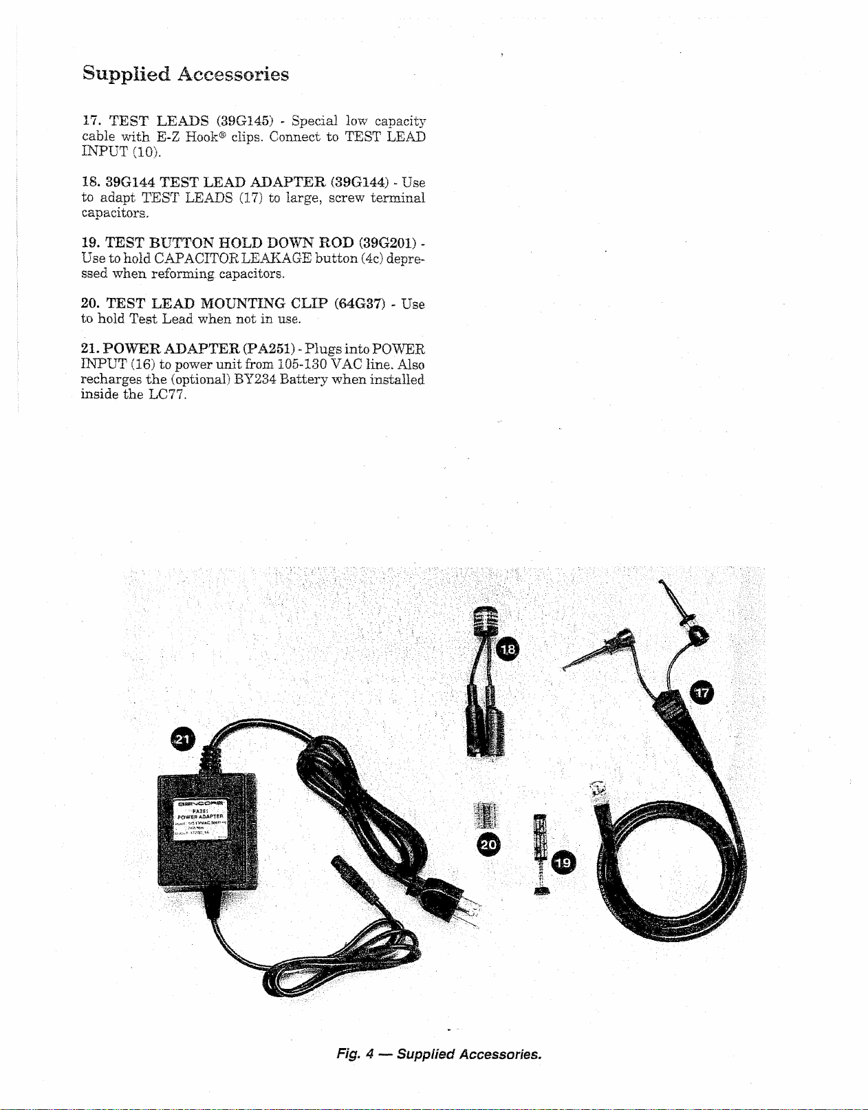
Supplied Accessories
17. TEST LEADS (39G145) - Special low capacity
cable with E-Z Hook® clips. Connect to TEST LEAD
INPUT (10).
18. 39G144 TEST LEAD ADAPTER (39G144) - Use
to adapt TEST LEADS (17) to large, screw terminal
capacitors,
19. TEST BUTTON HOLD DOWN ROD (39G201) -
Use to hold CAPACITOR LEAKAGE button (4c) depre
ssed when reforming capacitors.
20. TEST LEAD MOUNTING CLIP (64G37) - Use
to hold Test Lead when not in use.
21. POWER ADAPTER (PA251) - Plugs into POWER
INPUT (16) to power unit from 105-130 VAC line. Also
recharges the (optional) BY234 Battery when installed
inside the LC77.
Fig. 4 — Supplied Accessories.
Page 9
OPERATIO N
Introduction
Before you begin to use your LC77 “Auto-Z”, take a
few minutes to read through the Operations and Appli
cations sections of this manual and acquaint yourself
with the features and capabilities of your instrument.
After you have familiarized yourself with the general
operation of the LC77, most tests can be performed with
the information on the front panel.
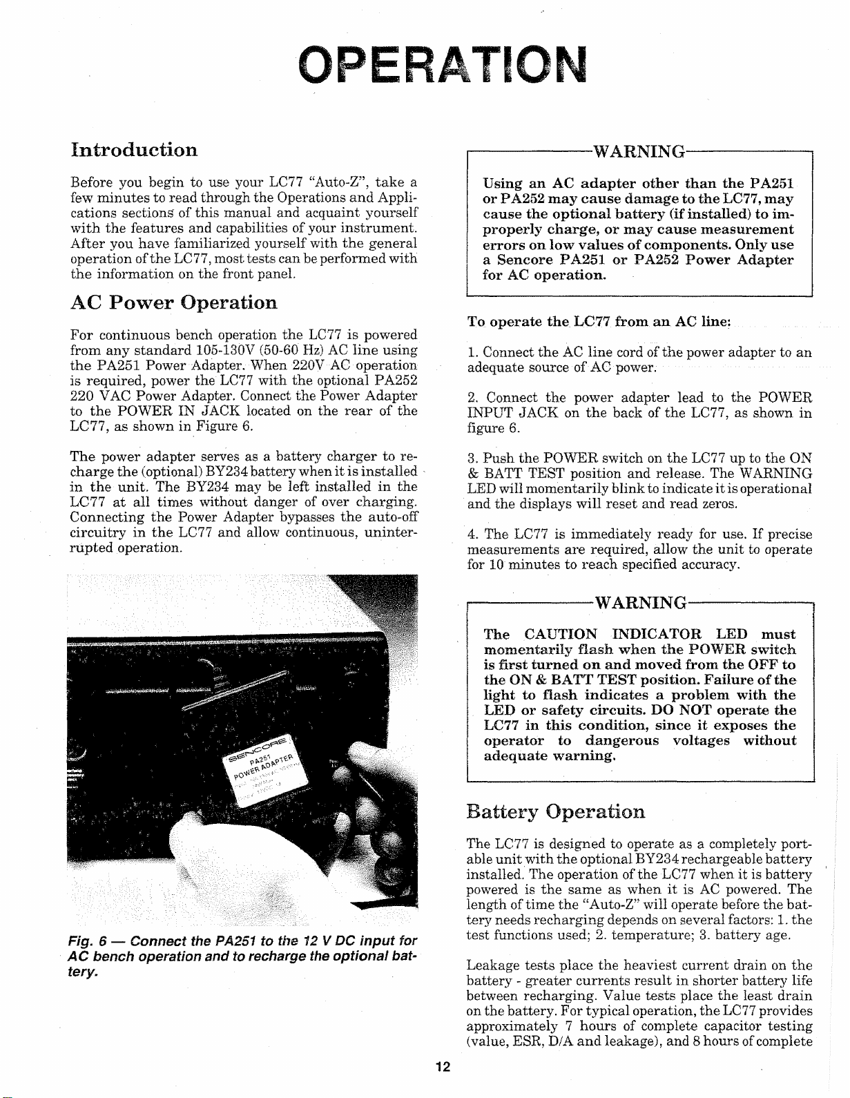
AC Power Operation
For continuous bench operation the LC77 is powered
from any standard 105-130V (50-60 Hz) AC line using
the PA251 Power Adapter. When 220V AC operation
is required, power the LC77 with the optional PA252
220 VAC Power Adapter. Connect the Power Adapter
to the POWER IN JACK located on the rear of the
LC77, as shown in Figure 6.
The power adapter serves as a battery charger to re
charge the (optional) BY234 battery when it is installed
in the unit. The BY234 may be left installed in the
LC77 at all times without danger of over charging.
Connecting the Power Adapter bypasses the auto-off
circuitry in the LC77 and allow continuous, uninter
rupted operation.
------------------
Using an AC a dapter other than the PA251
or PA252 may cause damage to the LC77, may
cause the optional b attery (if installed) to im
properly charge, or may cause measurement
errors on low values of components. Only use
a Sencore PA251 or PA252 Pow er A dapter
for AC operation.
To operate the LC77. from an AC line:
1. Connect the AC line cord of the power adapter to an
adequate source of AC power.
2. Connect the power adapter lead to the POWER
INPUT JACK on the back of the LC77, as shown in
figure 6.
3. Push the POWER switch on the LC77 up to the ON
& BATT TEST position and release. The WARNING
LED will momentarily blink to indicate it is operational
and the displays will reset and read zeros.
4. The LC77 is immediately ready for use. If precise
measurements are required, allow the unit to operate
for 10 minutes to reach specified accuracy.
WARNING
------------------
Fig. 6 — Connect the PA251 to the 12 V DC input for
AC bench operation and to rechar ge the optional bat
tery.
-------:-------------
The CAUTION INDICATOR LED m ust
momentarily flash when the POWER switch
is first turned on and moved from the OFF to
the ON & BATT TEST position. Failure of the
light to flash indicates a problem with the
LED or safety circuits. DO NOT operate the
LC77 in this condition, since it exposes the
operator to dangerous voltages without
adequate warning.
WARNING— :
............
..........
Battery Operation
The LC77 is designed to operate as a completely port
able unit with the optional BY234 rechargeable battery
installed. The operation of the LC77 when it is battery
powered is the same as when it is AC powered. The
length of time the “Auto-Z” will operate before the bat
tery needs recharging depends on several factors: 1. the
test functions used; 2. temperature; 3. battery age.
Leakage tests place the heaviest current drain on the
battery - greater currents result in shorter battery life
between recharging. Value tests place the least drain
on the battery. For typical operation, the LC77 provides
approximately 7 hours of complete capacitor testing
(value, ESR, D/A and leakage), and 8 hours of complete
12
Page 10

Notes
11
Page 11
inductor testing (value and ringing). These times, of
course, will vary with temperature and battery age.
As the temperature of the battery decreases, its capac
ity also decreases. The operating time between recharg
ings decreases at the rate of approximately 1 hour for
every 20 degrees F drop in temperature below 70°F.
The BY234 battery is a sealed, lead-acid type which
requires no maintenance other than recharging. As a
battery ages, it will require more frequent rechargings.
If used properly, the BY234 will provide several years
of service before needing replacement.
You can maximize the lifetime of the BY234 several
ways: 1. Never allow the battery to deeply discharge.
The LC77 has a built-in battery test and low battery
shut off circuitry. Check the remaining charge period
ically and recharge the battery before the low battery
circuit shuts the unit off. 2. Keep the battery fully
charged. The BY234 will not be harmed if it is left
installed in the LC77 during AC operation. Instead,
this will keep the battery fresh and ready for use and
will actually lengthen its useful lifetime, 3. Recharge
the battery before using it if it has sat idle for more
than a couple of weeks. Lead-acid batteries normally
lose some of their charge if they sit idle for a period of
time.
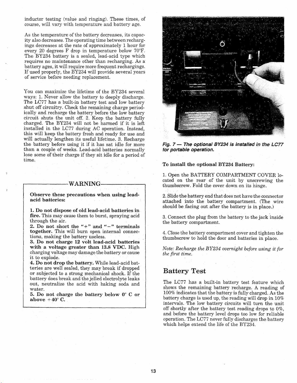
Fig. 7 — The optional BY234 is installed in the LC77
for por table ope ration.
To install the optional BY234 Battery:
----------------
Observe these precautions when using lead-
acid batteries:
X. Do not dispose of old lead-acid batteries in
fire. This may cause them to burst, spraying acid
through the air.
2. Do not short the “ 4-” and “ — ” term inals
to geth er. This will burn open internal connec
tions, making the battery useless.
3. Do not charge 12 volt lead-acid batteries
with a voltage greater than 13.8 VDC. High
charging voltage may damage the battery or cause
it to explode.
4. Do not drop the battery. While lead-acid bat
teries are well sealed, they may break if dropped
or subjected to a strong mechanical shock. If the
battery does break and the jelled electrolyte leaks
out, neutralize the acid with baking soda and
water.
5. Do not charge the battery below 0° C or
above +40° C.
—WARNING.
---------
— ------
1. Open the BATTERY COMPARTMENT COVER lo
cated on the rear of the unit by unscrewing the
thumbscrew. Fold the cover down on its hinge.
2. Slide the battery end that does not have the connector
attached into the battery compartment. (The wire
should be facing out after the battery is in place.)
3. Connect the plug from the battery to the jack inside
the battery compartment.
4. Close the battery compartment cover and tighten the
thumbscrew to hold the door and batteries in place.
Not e: Rec harge th e BY234 overnight before usi ng it f or
the first time.
Battery Test
The LC77 has a built-in battery test feature which
shows the remaining battery recharge. A reading of
100% indicates that the battery is fully charged. As the
battery charge is used up, the reading will drop in 10%
intervals. The low battery circuits will turn the unit
off shortly after the battery test reading drops to 0%,
and before the battery level drops too low for reliable
operation. The LC77 never fully discharges the battery
which helps extend the life of the BY234.
13
Page 12

To perform the battery test:
A u to O ff
1. With a BY234 installed, move the POWER switch
to the ON & BATT TEST position.
2. Read the percentage of remaining battery charge in
the LCD DISPLAY, as shown in figure 8.
3. If the reading shows 0%, the unit may not operate,
or operate for just a short time since the low battery
circuit turns the LC77 off at this battery level.
To conserve battery charge, the LC77 contains an auto
off circuit. This circuit keeps the batteries from running
down if you should forget to turn the unit off, but keeps
the “Auto-Z” powered up during use. The auto off circuit
will shut the LC77 off after approximately 15 minutes
if none of the front panel buttons have been pushed.
Pushing any COMPONENT TYPE button, COMPO
NENT PARAMETERS button, TEST button, or
momentarily moving the POWER button to the ON &
BATT TEST position will reset the auto off circuits.
The auto off circuits are bypassed when the LC77 is
operated from the PA251 AC Adapter/Charger.
To operate the LC77 using the optional BY234 bat
tery:
1. Install the BY234 battery into the LC77 battery com
partment.
NOTE: If you are using the BY234 for the first time,
be sure to charge the battery before using the LC77.
Though factory tested, the BY234 may not be charged
when you receive it.
2. Push the POWER switch to the ON & BATT TEST
position and release. The WARNING LED will momen
tarily blink to indicate it is operational and the displays
will reset and read zeros.
Fig, 8 — Push the Power switch to "On & Batt Test”
to r ead the remaining battery charge.
Recharging the Battery
The BY234 battery should never be allowed to remain
discharged for more than a few hours, since this will
shorten its lifetime. The battery must be recharged
whenever the battery test reads 0%. However, you
should recharge the battery more often than this to
lengthen the battery’s lifetime and keep the LC77 ready
for portable use at all times.
To recharge the battery, simply leave it installed inside
the LC77 while the unit in connected to the PA251 AC
Adapter/Charger and the Power Adapter is connected
to a source of AC power. The charging time required
to return the battery to 100% depends on how far it is
discharged. The battery will trickle charge while the
LC77 is in use and powered from the AC adapter, but
it will recharge the quickest if the POWER switch is
in the “OFF” position. Normally, a battery will com
pletely recharge in about 8 hours with the POWER
switch “OFF”.
3. The LC77 is immediately ready for use. If precise
measurements are required, allow the unit to operate
for 10 minutes to reach specified accuracy.
-----:---------
The CAUTION' INDICATOR LED must
mom entarily flash when the POWER switch
is m oved from the OFF to the ON & BATT
TEST position. Failure of the light to flash
indicates a problem w ith the LED or safety
circuits. DO NOT operate the LC77 in this con
dition, since it exposes the operator to dang er
ous voltages w ithout adequate warning.
------
WARNING
---------
■■■■■
..........
Test Leads
The test leads supplied with the LC77 (39G143) are
made of special, low capacity coaxial cable. Using any
other cable will add extra capacity to the meter circuits,
which may not be within the range of the lead zeroing
circuits. Attempting to zero the leads with another,
higher capacitance cable connected will cause the LCD
DISPLAY to show the message error. This indicates
that the value is beyond the zeroing limits of the LC77.
If the test leads ever require replacement, new leads
(part # 39G143) may be ordered directly from the: SEN
CORE SERVICE DEPARTMENT at 3200 Sencore
Drive, Sioux Falls, SD 57107.
14
Page 13
Test Lead Mounting Clip
A TEST LEAD MOUNTING CLIP (64G37) is supplied
with the LC77. This clip is useful to hold the test leads
out of the way when not in use, but keeps them ready
and within reach at any time. The mounting clip may
be attached on the top of the LC77, on the side of the
handle, or wherever it is most convenient. To mount
the clip, peel off the backing, place the clip in the desired
location and press it firmly in place.
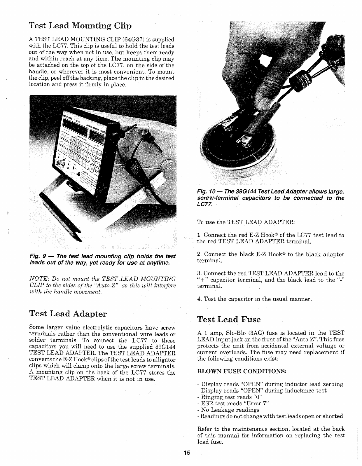
Fig. 10 — The 39G144 Test Lead Adapter allows large,
screw-ter minal capacitors to be con nected to the
LC77.
Fig. 9 — The test lead mounting clip holds the test
leads out of the way, yet ready for use at anytime.
NOTE: Do not mount the TEST . LEAD MOUNT ING
CLIP to the sides of th e “Auto- Z” as this will interfere
with the handle mov ement.
Test Lead Adapter
Some larger value electrolytic capacitors have screw
terminals rather than the conventional wire leads or
solder terminals. To connect the LC77 to these
capacitors you will need to use the supplied 39G144
TEST LEAD ADAPTER. The TEST LEAD ADAPTER
converts the E-Z Hook® clips of the test leads to alligator
clips which will clamp onto the large screw terminals.
A mounting clip on the back of the LC77 stores the
TEST LEAD ADAPTER when it is not in use.
To use the TEST LEAD ADAPTER:
1. Connect the red E-Z Hook® of the LC77 test lead to
the red TEST LEAD ADAPTER terminal.
2. Connect the black E-Z Hook® to the black adapter
terminal.
3. Connect the red TEST LEAD ADAPTER lead to the
“ + ” capacitor terminal, and the black lead to the
terminal.
4. Test the capacitor in the usual manner.
Test Lead Fuse
A 1 amp, Slo-Blo (3AG) fuse is located in the TEST
LEAD input jack on the front of the “Auto-Z”. This fuse
protects the unit from accidental external voltage or
current overloads. The fuse may need replacement if
the following conditions exist:
BLOWN FUSE CONDITIONS:
- Display reads “OPEN” during inductor lead zeroing
- Display reads “OPEN” during inductance test
- Ringing test reads “0”
- ESR test reads “Error 7”
- No Leakage readings
- Readings do not change with test leads open or shorted
Refer to the maintenance section, located at the back
of this manual for information on replacing the test
lead fuse.
15
Page 14
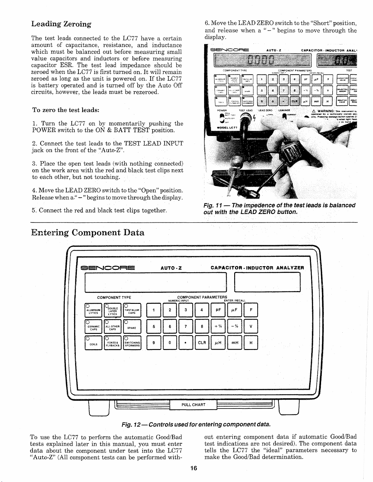
Leading Zeroing
The test leads connected to the LC77 have a certain
amount of capacitance, resistance, and inductance
which must be balanced out before measuring small
value capacitors and inductors or before measuring
capacitor ESR. The test lead impedance should be
zeroed when the LC77 is first turned on. It will remain
zeroed as long as the unit is powered on. If the LC77
is battery operated and is turned off by the Auto Off
circuits, however, the leads must be rezeroed.
6. Move the LEAD ZERO switch to the “Short” position,
arid release when a “ — ” begins to move through the
display.
CAPACITOR-INDUCTOR ANAL’
COMPONENT TYPE
COMPONENT PARAMETERS
—IIr™
0000000
i B Q 0 0 0 0 0 0 0
To zero the test leads:
1. Turn the LC77 on by momentarily pushing the
POWER switch to the ON & BATT TEST position.
2. Connect the test leads to the TEST LEAD INPUT
jack on the front of the “Auto-Z”.
3. Place the open test leads (with nothing connected)
on the work area with the red and black test clips next
to each other, but not touching.
4. Move the LEAD ZERO switch to the “Open” position.
Release when a “ — "begins to move through the display,
5. Connect the red and black test clips together.
Entering Component Data
S E N C O R E
AUTO - Z
TEST ICAO L£AD2£BO LEAKAGE
I CUKfltNT .
A WARNING: T** ic
optfra tf td by d v «n ia p«ri
oMy. i M U g * B utton 2!
• - *-• Ught
Fig. 11 — Th e impedence of the test feads is balanced
out with the L EAD ZERO button.
CAPACI TOR - INDUCTOR ANALYZER
COMPONENT PARAMETERS
nu m e r i c i n p u t en t er / rec a l l
o
ALUMINUM
IYTICS
0
CEHAtffC
CAPS
0
COILS
OMPONENT TYPE
o
DOUBLE
TANTALUM
LAYER
LYTICS
YOKES &
FLYBACKS
5
0
SWITCHING
XFQRME8S
[O
I ALL OTHER
I CAPS
0
CAPS
SPARE
Fig. 12— Controls used for enter ing c ompo nent data.
To use the LC77 to perform the automatic Good/Bad
tests explained later in this manual, you must enter
data about the component under test into the LC77
“Auto-Z” (All component tests can be performed with
pF PL?
CLR
mh
PULL CHART F—
out entering component data if automatic Good/Bad
test indications are not desired). The component data
tells the LC77 the “ideal” parameters necessary to
make the Good/Bad determination.
16
..........
mH
_______
Page 15
The component data which can be entered into the LC77
includes: component type, value, tolerance and rated
working voltage for capacitors, and component type,
value, and tolerance for inductors and coils. These
parameters are usually marked on the component, or
can be determined by looking the component up in a
parts list or replacement guide. The Applications sec
tion of this manual contains information on how to
identify capacitor and inductor types.
NOTE: All component d ata can be cleare d by pushing
the “CLR” button on the gray COMPONENT KEYPAD
twice.
To Enter Component Type:
NOTE: The compo nent type swit ches t ell th e LC77 wha t
kind of component is b eing t este d.
1. Press the desired COMPONENT TYPE button. Use
the beige color coded buttons when checking capacitors
and the blue buttons when checking inductors.
2. A red LED indicator in the corner of the COMPO
NENT TYPE button lights when that button is selected.
To Enter Component Value:
1. Enter a number, up to 3 significant digits, equal to
the value of the capacitor or inductor. (Example: “123”.
or “123000.”). Each digit will appear in the display as
a key is pushed.
a. The LC77 rounds the entry down if yo u enter a
number having more tha n 3 si gnificant d igi ts (Exam
ple : “1239” bec ome s “1230”).
b. TheLC77accepts numbers up to 6places before the
decimal. (Example: “10 000 0”). E ntries larger th an
this reset to 0.
c. TheLC77 accepts numbers up to 5 pla ces aft er t h e
de cim al for numbers le ss than 1. (Exam ple:
“0.00001”). Entries smaller than this re sult in “Erro r
2” . '
d. All unneces sary place holder dig its a re drop ped,
(Examp le: “.06 700” becomes “.067 ”).
e. Pu sh the “CLR” b utton once to clea r the va lue entry
a nd st art over.
To Enter Component Tolerance:
1. Enter a 1, or 2 or 3 digit number up to 100 which
equals to the “ + ” value tolerance of the capacitor or
inductor. Do not use a decimal.
2. Press the white “ + %” PERCENTAGE button.
3. Enter a 1 or 2 digit number up to 99 which equals
to the value tolerance of the capacitor or inductor.
Do not use a decimal.
4. Press the white PERCENTAGE button.
5. To check the entered percentage, press the white
“ -r %” or “ -%” button at any time.
SENCORE
COMPONENT TYPE
o
G
G-O
G
2-
O
CAPAC ITO R- IND UC TO R ANALYZER
a
©ENCORE
COMPONENT PARAMETERS
H H Q E D ' '
□ □ □ 0 0 0 H
b
CAPACITOR • INDUCTOR ANALYZER
2. Enter the desired CAPACITOR VALUE MULTIP
LIER or INDUCTOR VALUE MULTIPLIER.
a. The c apacitor value range is 1 pF to 19.9 F. The
inductor value range is .1 uH to 19.9 H. Ente ring
values beyond this ra nge causes an “E rror 2”.
b. The LC77 accepts non-convention al value n ota
tions, such as “.00001F”, 00002 uF” or “100000pF”
3. After entering the multiplier, the display momentar
ily shows the entered value and multiplier before re
turning to a “0000” reading. The LC77 is now ready
for the next parameter entry.
4. To check the entered capacitor value at any time,
push any beige colored CAPACITOR VALUE MULTIP
LIER button. To check the entered inductor value push
any blue colored INDUCTOR VALUE MULTIPLIER
button.
5. To change an entered value parameter, repeat steps
1 & 2.
CAPACITOR - INDUCTOR ANALYZES
n n
COMPQUH
MT P AR AWTjERS
L UJ
0000
0000
□ □ □ 0
d
Fig. 13 — To enter compon ent data select the COMPO
NENT TYPE switch which corresponds to the compo
nent being tested (a). Next, enter the component value
(b) and value tolerance (c). Finally, if te sting a
capacitor, enter the rated working voltage (d).
17
Page 16
To Enter Leakage Voltage:
1. Enter the desired voltage from 1 to 999.9 using the
gray keys on the NUMERIC INPUT keypad, A decimal,
followed by one digit may be entered, but is not neces
sary.
2. Push the white “V” key to enter the voltage. The
voltage will appear in the APPLIED VOLTAGE LCD
DISPLAY. For values greater than 25 volts the red
CAUTION INDICATOR LED will blink.
NOTE: The voltage is appl ied to the component Test
Leads when the CAPACITOR LE A K AG E test butt on is
pus hed.
3. To enter a different voltage, repeat steps 1 & 2.
Error Codes
Error 3 - Entered Value Beyond Range Of Test -
The component parameter entered via the keypad or
IEEE is beyond the limits of the automatic good/bad
test. The component may still be able to be tested, but
not for a good/bad indication.
Possible causes:
1. Performing an ESR test with a capacitor value of less than 1 uF
entered.
2. Performing a D/A test with a capacitor value of less than .01 uF
entered.
3. Performing an INDUCTOR RINGER test with an inductor value
of less than 10 uH entered.
E rror 4 - Value Beyond Zeroing Limit - The amount
of inductance or capacitance at the TEST LEAD INPUT
is beyond the range of the zeroing circuits. An open
(greater than 20 Kilohms) or shorted (less than 1 ohm)
test lead will cause the “OPEN” or “SHORT” annun
ciator to come on, rather than produce an “Error 4”.
Several error conditions may occur while using the
LC77 which cause an error message to appear in the
LCD display. These are usually caused by small errors
in the operation of the LC77, although severely defec
tive components may also cause certain error condi
tions. The error conditions are explained below.
E rror 1 - Component Type Selection E rro r - This
error occurs when a component test is attempted, and
either an incorrect COMPONENT TYPE switch is
selected for the test, or no COMPONENT TYPE switch
is selected when required.
Possible causes:
1. Performing a capacitor test with an inductor COMPONENT TYPE
switch selected.
2. Performing an inductor test with a capacitor COMPONENT TYPE
switch selected.
3. Performing the INDUCTOR RINGER test without an inductor
COMPONENT TYPE switch selected.
4. Performing any component test with the “Spare” capacitor COM
PONENT TYPE button selected.
Error 2 - Entered Value Beyond Range of Unit -
The component parameter entered via the keypad or
IEEE is beyond the measuring range of the LC77.
Possible causes:
1. The capacitance at the TEST LEAD INPUT is greater than 1800 pF.
2. The inductance at the TEST LEAD INPUT is greater than 18 uH.
8. The resistance at the TEST LEAD INPUT is greater than 1 ohm.
Error 5 - ‘No Voltage E ntered - This error occurs
when the CAPACITOR LEAKAGE button is pushed
and no test voltage has been entered.
Error 6 - Invalid IEEE Command - An improper
command was sent to the LC77 via the IEEE bus.
Possible causes:
1. Sending a command that is not recognized by the LC77.
2. Wrong command syntax.
NOTE: Ref er to the IEEE 488 Bu s Ope ration sec t i on of
this manu al for infor mation on usi ng the “Auto-Z” with
IEEE contr ol.
E rror 7 - Component Out Of Test R ange - The com
ponent under test exceeds the limits of the test which
was attempted.
Possible causes:
Possible causes:
1. Entering a capacitance value greater than 19.9 Farads, or less
th an 1 picofarad.
2. Entering an inductance value greater than 19,9 Henrys, or less
th an .1 microhenrys.
3. Entering a leakage voltage greater than 999.9 volts.
4. Entering a tolerance percentage greater than 4-100%, or less than
- 99%. ,
5. Entering a tolerance percentage that includes a decimal.
NOTE: E ntering a leakag e voltage les s t han 1 volt wi ll
set th e leakag e supply to 0 volts.
1. Measuring ESR of a capacitor having a value less than 1 uF.
2. Measuring capacitance value on an extremely leaky capacitor.
3. Attempting a capacitor value test with 1 ohm to 2 Megohms of
resistance connected across test leads.
18
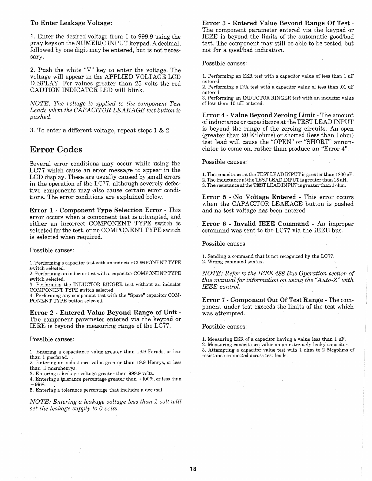
Page 17
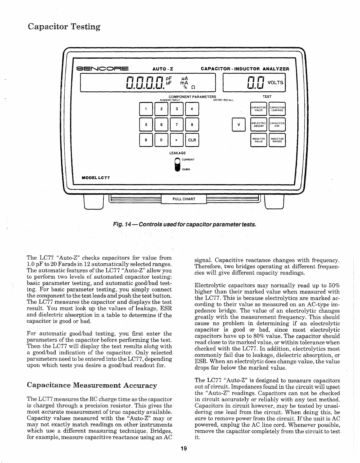
Capacitor Testing
S E N C O R E AU TO -Z
n n n n
U.U.U.U. m% n
NUMERIC INPUT ENTER / RECALL
(MODEL LC 77
Fig. 14— Controls used for capacitor p arameter tests.
CAPACIT OR - INDUCTOR ANALYZER
COMPONENT PARAMETERS
CLR
LEAKAGE
CURRENT
OHMS
PULL CHART
TEST
The LC77 “Auto-Z” checks capacitors for value from
1.0 pF to 20 Farads in 12 automatically selected ranges.
The automatic features of the LC77 “Auto-Z” allow you
to perform two levels of automated capacitor testing:
basic parameter testing, and automatic good/bad test
ing. For basic parameter testing, you simply connect
the component to the test leads and push the test button.
The LC77 measures the capacitor and displays the test
result. You must look up the values of leakage, ESR
and dielectric absorption in a table to determine if the
capacitor is good or bad.
For automatic good/bad testing, you first enter the
parameters of the capacitor before performing the test.
Then the LC77 will display the test results alofig with
a good/bad indication of the capacitor. Only selected
parameters need to be entered into the LC77, depending
upon which tests you desire a good/bad readout for.
Capacitance M easurement Accuracy
The LC77 measures the RC charge time as the capacitor
is charged through a precision resistor. This gives the
most accurate measurement of true capacity available.
Capacity values measured with the “Auto-Z” may or
may not exactly match readings on other instruments
which use a different measuring technique. Bridges,
for example, measure capacitive reactance using an AC
signal. Capacitive reactance changes with frequency.
Therefore, two bridges operating at different frequen
cies will give different capacity readings.
Electrolytic capacitors may normally read up to 50%
higher than their marked value when measured with
the LC77. This is because electrolytics are marked ac
cording to their value as measured on an AC-type im
pedance bridge. The value of an electrolytic changes
greatly with the measurement frequency. This should
cause no problem in determining if an electrolytic
capacitor is good or bad, since most electrolytic
capacitors have up to 80% value. The capacitor should
read close to its marked value, or within tolerance when
checked with the LC77. In addition, electrolytics most
commonly fail due to leakage, dielectric absorption, or
ESR. When an electrolytic does change value, the value
drops far below the marked value.
The LC77 “Auto-Z” is designed to measure capacitors
out of circuit. Impedances found in the circuit will upset
the “Auto-Z” readings. Capacitors can not be checked
in circuit accurately or reliably with any test method.
Capacitors in circuit however, may be tested by unsol
dering one lead from the circuit. When doing this, be
sure to remove power from the circuit. If the unit is AC
powered, unplug the AC line cord. Whenever possible,
remove the capacitor completely from the circuit to test
it.
19
Page 18
WARNING
Measuring Capacitor Value
When checking capacitors, remove the
capacitor from circuit if possible. Otherwise,
make sure the power is removed from the cir
cuit and the AC line cord to the unit contain
ing the capacitor is unplugged. Always con
nect the capacitor to the LC77 test leads be
fore depressing the CAPACITANCE VALUE
test button.
_______
___
_____
Measuring Small Capacitance
Values In Noisy Environments
The sensitive “Auto-Z” measuring circuits may be af
fected by large, outside signals (such as the AC fields
radiated by some lights and power transformers) when
small capacitance values are being measured. Special
circuits in the LC77 help minimize noise pickup and
stabilize the readings.
Measurements of small value capacitors in noisy envi
ronments may be further improved by grounding the
LC77 case to earth ground. When possible, power the
LC77 with the PA251 AC Adapter/Charger connected
to a properly grounded AC outlet. The PA251 Adapter/
Charger maintains the third wire ground shield and
keeps the noise away from the measuring circuits inside
the “Auto-Z”.
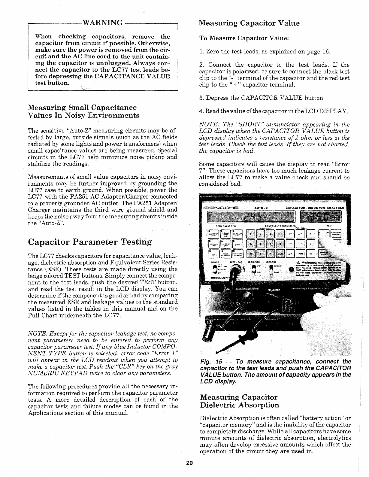
To Measure Capacitor Value:
1. Zero the test leads, as explained on page 16.
2. Connect the capacitor to the test leads. If the
capacitor is polarized, be sure to connect the black test
clip to the terminal of the capacitor and the red test
clip to the “ + ” capacitor terminal.
3. Depress the CAPACITOR VALUE button.
4. Read the value of the capacitor in the LCD DISPLAY.
NOTE : Th e “SHORT” annunciator appearing in t he
LCD di splay when the CAPACIT OR VALUE butt on is
depressed indicates a res istance of 1 ohm. or less at the
test leads. Check t he test leads. If they are no t s horted,
the capacitor is bad.
Some capacitors will cause the display to read “Error
7”. These capacitors have too much leakage current to
allow the LC77 to make a value check and should be
considered bad.
Capacitor Parameter Testing
The LC77 checks capacitors for capacitance value, leak
age, dielectric absorption and Equivalent Series Resis
tance (ESR). These tests are made directly using the
beige colored TEST buttons. Simply connect the compo
nent to the test leads, push the desired TEST button,
and read the test result in the LCD display. You can
determine if the component is good or bad by comparing
the measured ESR and leakage values to the standard
values listed in the tables in this manual and on the
Pull Chart underneath the LC77.
NOTE: Except for the cap acitor lea kage te st, no compo
nent parameters need to be enter ed to perf orm any
capa citor para meter test. I f any blue Inductor COMPO
NENT TYPE butto n is select ed, error code “Error 1”
w ill appear in the LCD readout when you atte mp t to
make a capacitor test . Push the “CLR" key on the gray
NU MERIC KEYPAD twice to clear any p arameter s.
The following procedures provide all the necessary in
formation required to perform the capacitor parameter
tests. A more detailed description of each of the
capacitor tests and failure modes can be found in the
Applications section of this manual.
Fig. 15 — To measure capacita nce, connect the
capacit or to the te st ieads and push the CAPACITOR
VALUE button. The amount of capacity appears in the
LCD display.
Measuring Capacitor
Dielectric Absorption
Dielectric Absorption is often called “battery action” or
“capacitor memory” and is the inability of the capacitor
to completely discharge. While all capacitors have some
minute amounts of dielectric absorption, electrolytics
may often develop excessive amounts which affect the
operation of the circuit they are used in.
20
Page 19
To check a capacitor for dielectric absorption, press the
DIELECTRIC ABSORPTION button and compare the
value to the chart. A fully automatic good/bad test may
also be used to test for dielectric absorption. This test
is explained in a later section.
charts. The capacitor is good if the measured leakage
is be low the amount shown in the chart. A fully automa
tic good/bad test may also be used to check capacitors
for leakage. This test is explained in a later section.
To measure capacitor dielectric absorption:
1. Connect the capacitor to the test leads. If the
capacitor is polarized, connect the red test clip to the
“ + ” capacitor terminal and the black test clip to the
terminal.
2. Depress the DIELECTRIC ABSORPTION button. A
will appear and slowly move through the display
indicating that the test is in progress.
3. Read the percentage of dielectric absorption on the
display.
4. Compare the measured D/A to the amount listed in
Table 1 for the capacitor type you are testing to deter
mine if the capacitor is good or bad.
NO TE: Depending on the capacitor’s value, type and
actual D/A, the LC 77 may, in a few cases, take up to 10
seco nds to displa y a reading.
Maximum Allowable Percent Of D/A
Capacitor type Maximum % of D/A
Double Layer Lytic Meaningless. D/A may normally
be very high.
Aluminum Lytic
Tantalum Lytic 15%
15%
CAPA CIT OR- IND UCT OR ANALYZER
COMPONENT PARAMETERS
“ i
1
5
9 0
2
=5'l
7 j
6
" I
H M I f I ”
— . — —
i.. H *>; \ loicu-ci’wc
j[ | I
1! li Trr —
MH mw fl
CLR I
A WARNING. .
op ei a tv d b y s * e ef tn f
1000 vofts id imnJs wftev.
Bo not capaeiim ut
i&a kage t«st.
tAPAC-iTO*
Pr&ssmg leakage to-
rj
D
1
Fig. 16— To test capacitor leakage, enter the working
voltage of the capacitor.
To measure capacitor leakage:
1. Connect the capacitor to the test leads. If the
capacitor is polarized, connect the red test clip to the
“ + ’’ capacitor terminal and the black test clip to the
terminal.
2. Set the LEAKAGE switch to the “Current” position
to read the leakage of the capacitor in uA or mA.
i
Ceramic
All others
Refer to the Applications section of this manual for
capacitor type identification.
Table 1— Maximum amounts of Dielectric Absorption.
10%
0%
Measuring Capacitor
Leakage (In microamps)
Capacitor leakage occurs when some of the voltage from
one plate flows (leaks) through the dielectric to the
other plate. The amount of leakage current through
the dielectric depends on the voltage applied across the
plates. For this reason, always check a capacitor for
leakage at (or as close as possible to) its rated voltage.
Voltages up to 999.9 volts may by applied with the
LC77.
To check capacitors for leakage, enter the working vol
tage of the capacitor and press the CAPACITOR LEAK
AGE button. Compare the measured leakage current
to the maximum allowable amounts in the leakage
3. Enter the normal working voltage of the capacitor
as explained earlier in the section “Entering Compo
nent Parameters” on page 16.
-----------
-------
WARNING
-------------------
The LC77 is designed to be operated by a tech
nically trained person who understands the
shock hazard of up to 1000 volts applied to
the test leads during the capacitor leakage
test. DO NOT hold the capacitor in your hand,
or touch the test leads or capacitor leads
when making the leakage test.
4. Depress the CAPACITOR LEAKAGE button and
read the amount of leakage in the LCD display.
5. Compare the measured leakage to the maximum
allowable amount listed in the Leakage Charts on pages
23 and 24 for the type, value, and voltage rating of the
capacitor you are testing.
NOTE: By enter ing the Com ponent Type and Value
p aramet ers for th e capac itor, the LC77 will a utomati
call y display the measured leakage along wi th the same
good!h ad indic atio n as the L eakage Charts.
21
Page 20

Voltage will be applied to the capacitor as long as the
CAPACITOR LEAKAGE button remains depressed,
and the leakage readings will decrease as the capacitor
continues to charge. Some capacitors may take a few
seconds to charge up to the applied voltage and may
cause the display to overrange with a flashing “88.88
mA” display. Continue to depress the CAPACITOR
LEAKAGE button until the leakage reading drops
below the maximum allowable amount listed in the
Leakage Chart.
When the CAPACITOR LEAKAGE button is released,
the LC77 discharges the capacitor through a low value,
high wattage resistor. The LC77 contains safety circuits
which sense the voltage across the test leads. Therefore,
when you release the CAPACITOR LEAKAGE button
after checking a large value capacitor, or after applying
a high leakage voltage, the display may show “Wait -
- - until the voltage is gone from the test leads. All
data input and test buttons will be locked out until the
display returns to “0000”.
LEAKAGE IN PAPER, MICA AND
FILM CAPACITORS
Paper, mica and film capacitors should have extremely
small amounts of leakage. Measuring any leakage
when checking these types of capacitors indicates a bad
component. The leakage reading may take 1-2 seconds
to show an accurate display while the capacitor charges,
LEAKAGE IN CERAMIC CAPACITORS
Leakage in ceramic capacitors is generally very low.
Ceramic disc capacitors, however, may have small
amounts of normal leakage. Ceramic disc capacitors
with voltage ratings above 50 WVDC should have less
than 1 uA of leakage. Some discs with working voltages
less than 50 WVDC may have a lower insulation resis
tance, and therefore may show somewhat more leakage,
depending upon manufacturer. In general, a 10 WVDC
ceramic disc capacitor may show as much as 16 uA of
leakage, and 25 WVDC ceramic disc may read up to
2.5 uA of leakage and still be considered good.
LEAKAGE IN ALUMINUM ELECTROLYTICS
Because of their larger value and higher leakage
characteristics, aluminum electrolytic capacitors may
take several seconds to charge. The LC77 display may
overrange (flashing 88.88 mA display) indicating the
charging current is greater than 20 mA while the
capacitor is charging. Table 2 shows the approximate
time that you can expect the LC77 to overrange for a
given capacitor value and applied voltage. After the
LC77 stops overranging, the current will drop in prog
ressively smaller steps as the capacitor charges. When
the cap is fully charged, the leakage readings will
change just a few digits up or down. You do not need
to wait until an electrolytic capacitor is fully charged
to determine if it is good. Simply keep the CAPACITOR
LEAKAGE button depressed until the leakage reading
falls below the maximum amount shown in the Leakage
Charts.
Capacity (uF)
Table 2 — Meter Overrange time versus capacitor
valu e and applied voltage.
LEAKAGE IN TANTALUM ELECTROLYTICS
Tantalum electrolytic capacitors have much lower leak
age than aluminum electrolytics of the same size and
voltage rating. Therefore, tantalum lytics will give a
leakage reading in a much shorter time than an
aluminum lytic - typically within 2 to 5 seconds. Com
pare the measured leakage with the amounts shown in
the leakage charts to determine if the capacitor is good
or bad.
LEAKAGE IN NON POLARIZED
ELECTROLYTICS
Electrolytic capacitors which are non-pol arized should
be checked for leakage in both directions. This requires
that you measure leakage twice, reversing the LC77
test lead connections for the second test. The maximum
allowable leakage for a non-polarized electrolytic in
either direction is twice that of a similar polarized elec
trolytic of similar capacitance value and voltage rating.
Leakage charts
The following leakage charts list the maximum amount
of allowable leakage for the most common aluminum
electrolytics and dipped soiled tantalum capacitors.
These charts are also duplicated on the pull chart below
the LC77. Good capacitors (as far as leakage is con
cerned) will measure lower than the amounts shown
in the Leakage Charts. When measuring leakage, you
do not need to wait for the readings to drop to zero or
to its lowest point. The capacitor is good for any leakage
reading which is lower than the amount shown in the
chart.
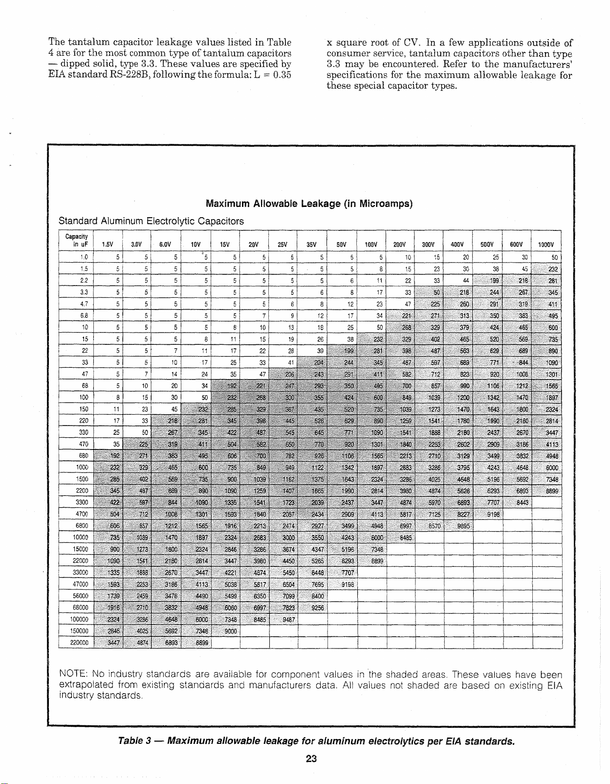
Leakage values shown in Table 3 for aluminum elec
trolytic capacitors are the worst-case conditions, as
specified by the Electronic Industries Association (EIA)
standard RS-395. The values are determined by the
formulas: L = 0.05 x CV (for CV products less than
1000) or L= 6 x square root of CV (for CV products
greater than 1000. (The CV product is equal to the
capacitance value multiplied by the voltage rating).
Page 21
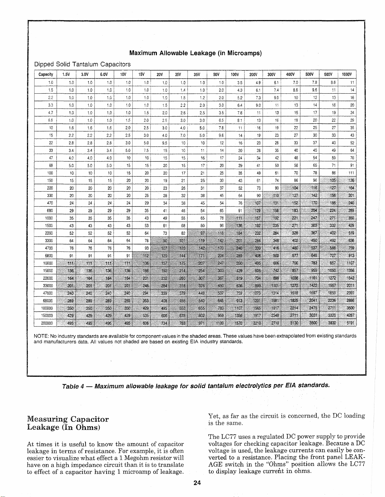
The tantalum capacitor leakage values listed in Table
4 are for the most common type of tantalum capacitors
— dipped solid, type 3.3. These values are specified by
EIA standard RS-228B, following the formula: L = 0.35
Maximu m Allowable Leakage (in Micro amps)
Standard Aluminum Electroiytic Capacitors
Capacity
in uF
1.5 V 3.GV 6.0V | 10V
1.0
1.5
2.2
3.3
4.7
6.8
10
15 5 5
22
33
47
68
100
150
220
330
470
680 192 271 383
1000
1500
2200
3300
4700 5Q 4
6800
10000
15000
22000
33000
47000
560C -:' 1739
68000
1000C0 1 2324
15000. 23-3
220 0CC ! 3 ^ 7
5
5 j 5
5 5 [ 5
5
5 5
5 5
5 5
5 5
5
5
5 10 I 20
8 15
11
17 33
25
35
V
232
285 *02
•345
422 697
606
735 1039
900
1C30 • 1541
1335
1593
|
1916'
5 5 5 5 5
5 ; 5
5
7
23
50
: 225
329 . :465 600 735 849 345
487 689
V2 1008
£57 12 >2 1565
■c?3
18 33 2570
2253
2459, 3*76 4490 5499 6350
2'< 0
3256 4648
£C25
437-
5 | 5
5 5
5
5 I 5 fi
5 | 8
7
10
14
J
30
45
218 281
267
319
569
:• : 844
1470
1300
2
j 30
3185
3B32
5592
6333
\#
5
5
5
11
•17 25 33 41
24
34
50 232
232 205 329
345 422
411
495
735
890 10 9C 1259
'.090
1301 ' '1593 1840
189“
2324
2814
3447
4:13
494 S 6060 6997 7823 9256
eooc
7346 9000
3899
20V
15 V
5
5
5
5
5
5
5 5
5 7 9
10 13
ll
15 19
17
22 28
35 47 235
22'
192
268 330
345 398 44 5
457
504 552 65 3
606 703 782
S3C 1039
'335 1541
2212
1916
2324
2583
2S46
3286
3447
3980
4574
422 1
5C 33
5617 6504 . 7695 ,L 9198
8485 .9487
7345
25 V 35V
247
357
545
’ ■63
1407
1723 2039 2437
2057 2434
24-4
3000
3674
4450
5450
7039
x square root of CV. In a few applications outside of
consumer service, tantalum capacitors other than type
3.3 may be encountered. Refer to the manufacturers’
specifications for the maximum allowable leakage for
these special capacitor types.
50V 100 V
5 5
5 5 5 j 8
5 5 e l 11 | 22
5 6
e
8 12
12
18 25
26 38
39 199
234 244
243 231 4-1
?S3 350
355 424
435
526 529
645
770 920
925
<122
1375 ■643 2324
1665 1990
2927
3550
4347
5255 S293
6448
.. 8400
5
8 j 17 33
17
520
7 7"!
■.*06
1342
2903 41-3
3499
4243
5195
7707
i
j
1
\
|
200V 300V
5
23
34 22* . 271
50
2G8
232 32 3 402
281 338
.157
345
582 712
495
70Q
600
849 . :. 1039; • 1200
735
1033 ■ 1273
aso
1259 .1541 1780
^030 154 1 1888
1 34-3
isc:
155 5
2213 2710 3129
1357
2683
3236 4025
2814
398-3
4874
3447
5517
R937
4943
S G3C
643 5
7348
B899
j .
10
15
47
400V
20 25
15
23 30 38
44
33
5C .. 213 244
225
329
437
: 597
857.
2253
3236 3795
4374
5S7 0 6S93
7125
■'8570.
260
■ 313.
■ ■ 379 ■
465
• 563
689
823
, 990 1106 ■ 1212
1470
t
2180
2602
4648
5628
8227
■ 9895
500V 600V
.....
19 9
291 ■ 319: 411
350 ■383.
424
' 520 563
629
' 771 ■ -844
• 920
■ 13 42
1643
'
1990
~ 2437
2909
3499
4243;
519 6 .. 5692
6293- 6893
7707
9198
I
...
1000V
30 50
45
232
218
- . 281
267.
345
• 495
465
600
689
890
1090
-cos
1301
• .. 1565
1470 1897
1800
2324
2180
2814
2670 3447
3186 4113
3332
4948
4648
. 6000
. . 7348
■ 8899
.8443
i
735
:
NOTE: No industry stand ards are available for component va lues in the shaded areas. These values have been
extrapolated from existing st anda rds and manufactur er s data. Ail vaiues not sh ade d are based on existing EIA
industry stand ar ds.
Table 3 — Maximum allowable leakage for aluminum e lectrolytics per EIA standards.
23
Page 22
Dippe d Solid Tantalum Capacitors
Capacity 1,5V
1.0
1.5
2.2
3.3
4,7
6.8
10
15
22
33
47
68
100
150
220
330
470
680
1000
1 SCO
2200
3300
4700
6800
1.0
1.0 1.0 1.0 1.0 1.0
1.0 1.0 1.0
1.0 1.0 1.0 1.0 1.0
1.0 1,0 1.0
1.0 1.0 1.0 1.5 2.0
1.6
2.2 2.2 2.2 2.5 3,0
2.8 2.8
3.4 3.4 3.4 5.0 7.5
4.0
5.0 5.0 5.0
10 10 10
15 15 15
20 20 20
20
24 24
29 29
35 35 35
43 43 43 43 53
52 52 52 52 64
64
76 76 76
91
1000 0 111- 111
15000
. 136
22000
33000
47000 240
g
o
100000
150000
200000
164
201 201 201
289
350
■V: .V 429
■ 495 495
3,0V 6.0V
1.0 1.0
1.6
4.0
20
64
91
.V-' 111
136
• 164
240 ' 240
239
'. 350
■ 429
10V
1.6 2.0 2.5
2.6 3.0 5.0
4.0 10 10
. 15
20 20 25
24 24
29 29 35
64
91 91
r i
136
136
164 134 201
20 1 246
240
289
350
259 353
350 429
429 425 535 606 573 5 G2
495 495
Maximum Allowable Leakage (in Microamps)
15V
1,0
1.0
1.0
1,0
1.0
1,5 2.0 2.6 2.5
15
15 20
20
20
20 20
29
.' 41
35
43
64
78
76
93
' M
-36
166 192 214 254 303
294
605
25V 35V 50V
20V
1,0 1.0 1.0
1.4
1.0
1.0 1,8 1.2 2.0 5.2 7.3
1.5 2.2 2.0 3,0
2.5
3.0
3.0 4.0
7.0 5.0
4.0
9.5 10 10 12
■ 15 10 11
15 15 16
20 15 17 20
20-
19 21
23 26 31
28 32 38
34
46
49 55 65
61 68
73 82
90
W
’.G7
120 1- 12 170
144 171 204
129
157 175
1.0 2.0
3.0 6.5
5.0
17 21 25
25 30
45 54
38
54
80 96
97
■ 19 142
2C 7
100 V 20 0V 300V
1.0 3.5 4.9 6.1
4,3
6.4
3.5
7.6 11 13
9. 1 13
7.8
9.6
65
78
11 | -16
14 19 23
. 16 23
14
20 28
17
24 34
29
35 49
43 61
37
52
45
54 90 1 1C 127
76
91
111
133 192
154 23 2
r e
2C1 28 4
24 C 339
239
247
35 C
42S
■73
307 367
449
537
763 1107
959
11 CO
513
635
753 1073
1356
157C
252 25C
31S 375 450
284
339
455 540 645 913 1291
408
553 655
495
734 78 3 S71
■- 734
; ^ 1565
400V
7.4
6.1
9.0 10
9.0
11 13
16 18
19 22 25
28 33
35 40
42 48
41 50 58
61 70
74 86
73 90
500 V
7.0 7.8
'9.6 11 14
8.6
' 12 13 16
15 17
.27
104
;: i16
14
20
30
37
45
54
65
78
96
-,-;■ 127
600V 1000V
8.6
16 20
19 24
22
27
33 43
40 52
49 64
59 76
71 91
86 111
105 136
■v. 164
142 156 201
107 131 152 170. 1 8 6 24 0
;;V - 224
■29 158 183
'57
' 19 2 221
' '235
284
.348
416 480
500
408
606-
435
742
605
£99
839 11C1
:2'4 ' 1518
15 S"
19-7
234 3
1917
271 0 3130
2210
271
328
402
577
700 • 783
857 •. 959
1038
1272 1422
1825
2214 2475
J27--1 3031 3320
204
V 247
: r- ” ; 303
367
271 350
332 429
402 519
• .450 •4 92
■ 537
■•645
583 75S
- 707
• 913
. 357 1107
1050. . . 1356
. . :1161' 1272 1642
1557
. ' 2011
1697
' 1859
' 23S 3
.•'2041. 2236
2711
■ 3500
3500
3830
; 51 91
11
29
35
289
636
2886
4287
NOTE: No i n du s t ry standa r ds a re availab l e for com p onen t val u es in th e shad ed ar eas . These valu e s h a v e b een extra pola t ed from existing standards
an d ma nufa c t urer s da t a . All values not sh aded ar e based on existing EIA ind u st r y st anda r ds.
Table 4 — Maximum allowable leakage for solid tantalum electrolytics per EIA sta ndards.
Measuring Capacitor
Leakage (In Ohms)
Yet, as far as the circuit is concerned, the DC loading
is the same.
The LC77 uses a regulated DC power supply to provide
At times it is useful to know the amount of capacitor
leakage in terms of resistance. For example, it is often
easier to visualize what effect a 1 Megohm resistor will
have on a high impedance circuit than it is to translate
to effect of a capacitor having 1 microamp of leakage.
voltages for checking capacitor leakage. Because a DC
voltage is used, the leakage currents can easily be con
verted to a resistance. Placing the front panel LEAK
AGE switch in the “Ohms” position allows the LC77
to display leakage current in ohms.
24
Page 23

To measure capacitor leakage in ohms:
1. Connect the capacitor to the test leads. If the
capacitor is polarized, connect the red test clip to the
“ + ” capacitor terminal and the black test clip to the
terminal.
2. Set the LEAKAGE switch to the “Ohms” position to
read the leakage current in ohms.
3. Enter the normal working voltage of the capacitor
as explained earlier in the section “Entering Compo
nent Parameters” on page 16.
•WARNING-
The LC77 is designed to be operated by a tech
nically trained person who understands the
shock hazard of up to 1000 volts applied to
the test leads during the capacitor leakage
test. DO NOT hold the capacitor in your hand,
or touch the test leads or capacitor leads
when making the capacitor leakage test.
4. Depress the CAPACITOR LEAKAGE button and
read the amount of leakage resistance in the LCD dis
play.
8 ■
PF
+ %/
MH
‘J u
■-%
mH
COM P O N E N T T YPE
*
in i£S :
_
| vOuts 8
©
«
f*
1
2
S
6
0
. 9
•1
'1
' I
4
CLft
•
m
CfflAWlC
CAPS
COU.fe
Fig, 17 — Piace the LEAKAGE switch in the “ohm”
position to measure leakage resistance.
Measuring Capacitor ESR
Fig. 18— Depress the ESR button and r ead the amount
of ESR in the LCD display.
To measure capacitor ESR:
1. Zero the test leads, as explained on page 16.
V
2. Connect the capacitor to the test leads. If the
capacitor is polarized, be sure to connect the black test
clip to the terminal of the capacitor and the red test
clip to the “ ~r ” capacitor terminal.
3. Depress the CAPACITOR ESR button and read the
amount of ESR in ohms on the digital display.
4. Compare the measured ESR to the value listed in
the following ESR tables for the capacitor type, value,
and voltage rating of the capacitor you are testing.
NO TE: By e ntering the com ponent type, wor king vol
tage, and val ue parameters for the capacitor, the LC77
will automatically display the measu red ESR al ong with
the same goodlbad indication as the ESR tab l es.
Equivalent Series Resistance (ESR) occurs when a
capacitor develops abnormally high internal resistance.
The LC 77 tests capacitors for abnormal amounts of in
ternal resistance using a patent pending ESR test.
To test a capacitor for excessive ESR, simply press the
CAPACITOR ESR button and compare the measured
ESR to the maximum allowable ESR listed in Table 5
for aluminum electrolytic capacitors, and Table 6 for
tantalum capacitors. A fully automatic good/bad test
may also be used to test capacitors for excessive ESR.
This test is explained in a later section of this manual.
25
Page 24

Maximum Allowable ESR (in Ohms)
Standard Aluminum Electrolytic Capacitors
CAPA CITY
in u F 1.5V 3.0V 6.0V j 10 V
1.0
663 653
U Z
1.5
2.2 332 302 302 J 302 2H
3.3 201 ! 23'1 201 1 201
4.7
6.8 98 j SS 98 | 96
10
15
22 30 * 30 30 j 30 21 21
33 20 20 20 j 20
47
68
100 6.63 6.63 6.63 6.63
150 4.42 4.42 4.42 4.42 3.10 3.10
220
330
470
680 .976 .976 .976
1000 .663 .663 .663
1500
2200
3300
4700
680C
10000 .066 .066
15000
22000 .030 j .030
33000
47000 .014 .014 .0 ^
56000 { .012 . . -.012
68C00 ] .010 ’ .010 010 .010
i42
14 1 j 14‘
66 i - 65
U
j 44
14
9.76 9.76
3.02 3.02
. 2.01 2.01
1:41
.
1- 4 1
.442 .442
.302' .302
m
*
.098 .098
.020 .020 020
c
3
663 663
442 | 442 | 310 310 | 310 | 221
141 j 141 99 99
66 1 66 46 46 46 I 33
44 j 44
'A
14 j 14 9.88 9.88
9.76 9.76 6.83 6.83
3.02 3,02 2. 11 2.11 | 2.1 1 ] 1.51
2.01 2.01
1.41 1.41 .988 [ .986 j .988 1 .706
.442 ,442 j .310
.302 .302 | .211 j .211 [ .211
.201
p i
.141 .141 .099 1 .099 .099
.098 .098 .06 3 .0 6fc
.066 .066 .045 .0*8
.044 .
C30
.01 2 .0-2
15 V | 20V 25V | 35V
464 ! 464
141 141
68
31 31
14 14
4.64 4.64 4.64 | 3.32 3.32 2.65
1.41 | 1.41 j 1. 41 j 1.01
.976 .683 [ .683 { .683
.464 1 .464 ! ,464 .332
.663
j
.201 j .141 | .141 ,141
.0 31
.02’
.030
.C20 .0-4
.CM
.0-0
464
j
464 332 332 265
211 | 211
68
.310 | .310
.03-
C2-.
C“4 .014
.010
j
151 151
141
j
101 101 80 80 80
99 j 71
68
j
49
31 j 22
21
j
14 ; 10
9.08 | 7.06
6,83 I 4.68
3.10 ! 2.21
.488 .488 | .390 .390 .390
.221 .221
.151 .15'
.1 01
.07 1 .07'
.C SS .049 .C-iS .035
.043 .033 .033
.03 1
.02^
.022
.015
.010
O'C
i ■
50 V 100 V 200 V 300V
265 265
177 177 177
221
121 121 12 1 121'
71 56
49 39
33 27 27
22
18 18
15 12 12 12
15
10 8.04 8.04 8.04
7.06 5,65 5.65 5.65
4.88
3.90 3.90 3.90
2.65 2.65 2.65
1.77
2.21
1,51 1.21 | 1.21
1.01 | .804 j .804
.706 | .565 .565 .565
.332 j .265 .265 .£•35 • .265 .265
.1 01 .03 0 .080 .030
.022
.CI S
.010
..........................
.1.77
.177
.177
.121
■ .121
.056
.056
.C3S
.027 .C27 .027
.016
.018
C 12
012
i
..................-.........
56 56 56 56
56
39 39
27
18 18 18 18 18
1.77 1.77 1.77 1.77
1,2.1
,804 | .804 .804
.17 7 .177 .177 .177
• - . .• .121
.05 6 .056
.03 9 ■■ ...039 .039 .039
.018
■012
400V 500V 600 V
265 265 265
177
8.04 8.04 8.04 8.04
5.65 5.65 5.65 5.65
3.90 3.90 3.90 3.90
1.21 1 . 21
.565
.390 .390
.121
.080 .030 .080 ;; r .080
.C 27
.018
.012
177 177 177
121 121 121
80 80 80 80
39 3S
27 27
12 12
2.65 2.65 2.65
• .565 .565 .565
■ -121
.056 .056
• .027, : . : : .027
.018
.012
39
27
12
. 1.21
.804
.350 .390
. .265.
.121
.018
.012
/ 121
1000V
1.77
.265
.177
'
.121
• ; .056
.039
.027
.01 8
.012
56
39
27
12
'
NOTE: N o industry standards are available for component values in the shaded area. These values have been extrapolated from existing standards
and manufacturers data. AH values not shaded are based on existing EIA industry st and ard s.
Table 5 — Maximum allowable ESR for aluminum electrolytics per EIA standards.
Capacitor Automatic
Good/Bad Testing
microprocessor memory. The tables and formulas in the
“Auto-Z” memory are the same as those printed in this
manual, and are based on EIA standards and manufac
The LC77 “Auto-Z” can automatically display a “good/
bad” indication for capacitor parameter tests. The au
tomatic tests are much faster than manual parameter
tests, since you do not have to look up the result in a
chart, or interpolate between listed values. The LC77
compares the measured values of dielectric absorption,
leakage, and ESR to tables and formulas stored in its
turers' data. Not every parameter for some capacitor
types are specified by EIA standards or manufacturers’
data. The LC77 will not produce a “good/bad” display
for capacitor parameters not covered by industry ac
cepted standards. The capacitor types and parameters
which will produce a “good/bad” indication are listed
in Table 7.
26
Page 25

Maximum Allowable ESR (in Ohms)
Dipped Solid Tantalum Capacitors
CAPACITY
in uF
1.5V
3,0V 6.0V
133
1.0
88.4
1.5
2.2
60.3 60.3 60.3 36.2 36,2
3.3
40.2
4.7
28.2 28.2
6.8
19.5 -19. 5 19.5 11.7 11.7
10
13.3 13.3 13.3 7,96 7.96
8.84
IS
22
6.03 6.03 6.03 3.62 3.62
4.02
33
47
2,82 2.82 2,82
68
1.95
100
1.33 1.3 3 .
150
0.88 0.86 0,88 0.88
220 0.60 0.60 0.60
330
0.40 0.40 0.40 0.40 0.40
470
0.28 0,28 0.28 0.28
680
0.20 0,20 0.20 0.20
1000
0.13 0.13
1500
0.09 0.09
2200
0.06
0.04
3300
4700
0.03
6800
0.02 0.02 0.02 0.02 0.02
133 133 79.6 79.6
88.4 88.4
40.2 40.2 24.1 24.1
28.2 16.9
8.84 8.84
4,02
4.02
1.95 1,95
1.33 -
0.13
0.09 0.05 0.09
0.06 0.06 0.06
0.04 0.04 0.04 0.04
0.03 0,03
10V 15V 20V 25V
53.1 53,1
5.31 5.31
2,41
1.69
1,17 1.17
0.80 0.80
0.60
0.13
0.03
— y— ■- -~-
l
35V
79.6
53.1
36.2 36.2 30.1
24.1
16.9 16.9 16.9
11.7 11.7 11.7 11.7
7.96 7.96 7.96
5.31 5.31 5.31 5.31 . 5.31. v* 5.31 j 5.31 '. ■ 5.31' /.
3.62 3.62
2,41
2.41
1.69 1 .69 1.69
1.69
1.17
0.80 0.80
0,88 0,88 0.53
G.88
0.60
0.60
0.40
0.26 0.28
0.28
0.20 0.20 0.20
0.13 0.13
0.09 0.09
0.06 0.06 0.06 0.04
0.04
0.03 0.03 0.03
0.02 0.02
66.3
79.6
53.1 44.2
24. 1
20.1
14,1 14.1 i
3.62
2.41
2.41
1.17 1.17 ■••!
1.17
0.80
0.60
0,36 :;.3C : -■ a36-'-: j'VM fe.:'.
0,40 0.24
0.17 0.17 . " .c: i7” .]. - 0:if7-:.
0;12
0.06
0.13
0.05 0,05 0.05, 0;05>
0.04
0.02
0,02
.0.01 : ■ Q-0-!: ■
0.01
100 V | 20QV
50V
66.3 .-65.3 ’ i . 6S.3 . • 66.3' | -. 66.3 ' 56.3 -.66,3 j 56.3
.'44-.2; j' 44.2 '44.2' -I'.- 44;2- ■
44.2
30.1 - p 30:i 30.?.. f 3G.1- ..j ■ 30:s-- j ' 30.1-!' ‘
30.1
'2 0 1 .' j; '20,V'.“ 2 0.l' j 20.5. -j ■ 2 D .T y j 20.1
20.1
7.Si 796 j 7.55 .
3 62 3.S2 '
2.41 ‘“V iV ■
\c = I . 1.6 9.. } ■ .-1.S9' '■ •' 1 59-.. j 1.69
3.62 ; 3.52 ; 3.52.
2.41 ■
' p 7
0.80 0.80 •' '■ ■ MD ■ 5-80:^;!... 0.S0
e.=:; ■ 0.53 !; p s f >'i0,5*7>
r..~. ' . 0.24-V
0.12
0.0s !.--a:os.
C L'.; ! !& pf
■jc :; j- c.0&:/;. ^ 0 0 2 ;
.0.02 ."'!
.[■'
oo& :
q:p i;
’ .ffiOi
400V
300V
; .1 ^ . - |-„v«-.1 ■ ) : 14.2 R f
71.7 ■ | 11,7 J 11.7 ■■■
■ .7.96." 7,96..
7S5
. . 2.41 1 . -2.V41- ' ;
■.
■ Vi?.5 -...; S 1.17
3,35 v ■ i' ■ .036./; ■
.. o !if !!j .0:12^ !!
•;s.3 8. ^ e . 6 8
!;■ Q.B4 k";
;> p ;6^vl :! !sf e p2^
.o!fi2!':'j- ^ i l 2 >'.
.! ='
5Q0V | S00V
■■■ 442 . j ■■ 44.2 '- [-..±4.2 i
.' s . 3 r ; '
3.62:.' 3.62 ■
■2.41 ■■■■'. ■
1.69'" - 1.59
.. ''0:80 ^;;:
.>d!pB>;-
■ 0.01; .'.
■ 11.-7. --
7.S6 "
3.31. !;,!
■2.4v;;.. 241
'•'■1:17-. •’
. !.4S 3 ::'
w Ql36.:;.'
;;>!o:17 S '
■ -0.0&
. ,0.0,5 ..>:
Y
C.01'--
j
1000V
. .-30.1
20.1 ;
f ' -
' \ \ T
. 796
;. 531 !
- 36 2
■ . 1.69
1,17 -
■ C80
; 053: '-
':p .36,;:
" ! ' P #
0.03
e,05;:;
:v 0.04^!
■ ■■■- -0.0.1 • ' •
1
NOTE: No industry standards are available for component values in the shaded areas. These values have been
extrapolated from existing standards and manufacturers data. Ail values are based on existing EIA industry
standards.
Table 6 — Maximum allowable ESR for dipped solid tantaium electrolytics per EIA standards.
27
Page 26

CAPACITOR TYPE
TESTS TO PERFORM
Value Leakage D/A ESR
Aluminum Lytic
Double Layer Lytic
Tantalum
Ceramic
All other caps
X
X
X
X
X
X X X
X
X
X
X
X X
(paper, film, mylar, etc.)
Table 7 — The LC77 will provide an automatic good/bad test of the capacitor parameters sh own here.
To perform an automatic good/bad test, you must enter
the capacitor type, capacitance value, and voltage rat
ing of the capacitor to be tested so the LC77 can deter
mine the good/bad limits. If you desire to grade
capacitors according to value, you must also enter the
desired “ + ” and value tolerances. The value toler
ances, however, do not need to be entered for automatic
good/bad tests of leakage, ESR, or dielectric absorption.
TEST
Cap. Value X
Cap. Leakage X
Cap. ESR
Cap. D/A
CAP
VALUE
X
X
+ % ;
-% CAP
VOLTAGE
X X
X X
X X
COMPON.
TYPE
X
NOTE: The leakage test function may requir e from 4 to
8 di splay updates for the leaka ge value to settl e before
a good/bad indication is di sp la yed.
X
Table 8 — These parameters must be enter ed into the
“Auto-Z” fora complete good/bad test of a capacitor.
To perform an automatic good/bad capacitor test:
1. Zero the test leads.
2. Connect the capacitor to the test leads.
3. Place the LEAKAGE switch in the “Current” posi
tion. The LC77 will not give a good/bad reading with
the switch in the “Ohms” position.
4. Enter the component type, value, and voltage rating
of the capacitor to be tested. (Refer to the section “En
tering Component Data” on page 17.)
5. To grade capacitors according to value, enter the “ + ”
and value tolerance.
6..Push the desired capacitor TEST button.
7. Read the test result in the LCD along with the good/
bad indication.
Fig . 20 — The LC77 provides an automatic good/bad
indic ation of each capacitor parameter.
8. The display m ust show a “good” reading for all of
the tests listed in table 7 under the type of capacitor
being tested.
28
Page 27

Inductor Testing
Fig. 21 — Controls used for inductor testing.
The LC77 “Auto-Z'" measures the true inductance of
coils using a fast, reliable patented test. Coils from
.luH to 19.99 H are automatically measured for value
by connecting the test leads and pressing the test but
ton. A patented Ringer test dynamically checks the “Q”
of the coil and provides a proven good/bad check.
Balancing Out Lead Inductance
The LC77 test leads have a small amount of inductance
which must be balanced out for greater accuracy when
measuring inductor values smaller than 1000 uH, This
lead inductance is balanced out with the LEAD ZERO
switch.
To balance out test lead inductance:
1. Connect the test leads to the TEST LEAD INPUT
JACK on the LC77.
2. Connect the red and black test clips together.
3. Move the LEAD ZERO switch to the “Short” position,
and release when a begins to move through the
display.
4. The test lead inductance will automatically be ba
lanced out for all subsequent inductance tests as long
as the “Auto-Z” remains on.
Fig. 22 — Connect the test leads together and push
the LEAD ZERO button to “Short” to balance out the
test lead impedence when checking small value induc
tors.
NOTE: Z eroing or not zeroing t he test lead s will not
affect t he Ringer test.
Page 28

Inductor Value Testing
lower the Q of the coil, causing the LC77 display to
read “BAD” and show less than ten ring’s.
Inductors are tested for value with the LC77 by simply
connecting the inductor to the test leads and pushing
the INDUCTOR VALUE button. No component type
switches need to be selected to measure inductance
value. Make sure none of the beige capacitor type but
tons are selected, or the LC77 will only display “Error
1” when the inductor test button is pressed.
NOTE: On ly the blue co l or codedLC77 bu ttons are us ed
for i nduct or value testing .
To m easure inductance value:
1. Zero the test leads.
2. Connect the inductor to the test leads.
3. Push the INDUCTOR VALUE button.
4. Read the inductance value on the LCD display.
NO TE: The LC77 display will read “OP EN” if the com
ponent conn ected to the test leads has more than 20
kilohms of resista nce when the INDUCT OR VALUE
button is pressed. Check the co nnections to the inductor.
If you are testing a multitap coil or transformer, be sure
yo u are connected to the proper taps. If the connection s
are good, the inductor ha s an open wi nd ing and is bad.
In addition to air core coils and RF chokes, vertical
deflection yokes, horizontal flyback transformers and
switching power supply transformers are reliably
checked with the Ringer test. The LC77 automatically
matches the coil impedance to the necessary testing
parameters for the inductor type when the proper induc
tor COMPONENT TYPE switch is selected. Simply
select the component type and press the INDUCTOR
RINGER test button to obtain the good/bad indication.
Refer to the Applications section of this manual for
more details on inductor types.
t v ,'-:;
COILS
, |Q r
bp mb.
1°
1 YOKES & SWITCHING
1 FLY BACK S XFORMERS
'o
u
L B m 21
: 5 I. a ll OTi- .rr,;; >
i ,PS | I CAP., i
'C <rtli 'Srti
I
o
Inductor Automatic
Good/Bad Testing
The LC77 provides two good/bad tests for inductors.
The first good/bad test is the patented Ringing test
which checks for shorted turns (low Q) in the inductor.
The second LC77 good/bad test compares the actual
measured value of an inductor to a user-entered value
and tolerances. Both tests will display a good/bad read
out along with the measured parameter.
NO TE: The blue color co ded TEST and COMPONENT
TY PE Select bu ttons are used for inductor go odlbad
tests.
Checking Inductors
With The Ringer Test
A shorted turn in many coils will go unnoticed with a
value test, since the shorted turn changes the induc
tance value only a small amount. The patented Ringer
test, however, provides a fast and accurate good/bad
indication of non-iron core coils larger than 10 uH by
checking their quality or “Q” factor. The Ringer test is
sensitive enough to detect even a single shorted turn
on a coil. The “Auto-Z” measures Q by applying a pulse
to the coil and counting the number of ringing cycles
until the ringing dampens to a preset level. A good coil
will indicate “GOOD”, and 10 or more rings will be
shown in the LC77 LCD display. A shorted turn will
111
Fig. 23 The inductor COMPONENT TYPE switches
match the Ringer test circuits to the inductor impe
dance.
FUSE
To perform the Ringer test:
1. Connect the coil to the LC77 test leads.
2. Select the proper inductor COMPONENT TYPF
switch.
3. Push the INDUCTOR RINGER button.
4. Read the condition of the coil as “GOOD” or “BAD”
in the LC77 LCD display.
Sp ecial Notes On Using Th e R inging T est:
1. Do no t ring c oils and transform ers hav ing lamin ated,
iro n cores, such as pow er transforme rs, filt er chokes and
audio outp ut transformers . The iron core will abs o rb
the ringing ener gy and p roduce unreliable t est resul ts.
2. Good coils b elow 10 uH may not read “GOOD ” because
the small i nduc tance value may not allow th e coil to
rin g. Compare the nu mber o f ring s to a known good coil.
Page 29

The patented S enco re Ringing test is bas ed on th e Q of
the coil. Howe ver, the readin gs on the “A uto-Z” may not
agree with the Q readings obt ain ed using a “Q Mete r”
or bridg e . This is becaus e the Ringin g tes t h as been
simp lified to provide a simple goo d/bad test, rather th an
a frequency d ependent reactan ce!resistan ce ratio.
Testing Inductor Values
Using The Good/Bad Test
The LC77 will automatically compare the measured
value of an inductor to its marked value and display a
good or bad result, based on the component being in or
out of tolerance. In order for the “Auto-Z” to compare
the marked value to the measured value you must prog
ram the inductance value and tolerance into the LC77
using the NUMERIC KEYPAD. Then when you push
the INDUCTOR VALUE button, the measured induc
tance value will be displayed along with a good/bad
reading based on the programmed tolerance.
IEE E 488
BU S OPE RA T IO N
All of the LC77 “Auto-Z” tests may be totally automated
or incorporated into an automated test system through
the use of the IEEE 488 General Purpose Interface Bus
(GPIB). The LC77 is interfaced to any IEEE system or
controller using the (optional) IB72 IEEE 488 Bus In
terface accessory. The IB72 makes the “Auto-Z” a fully
compatible IEEE instrument.
As an IEEE compatible instrument, the LC77 may have
either of two functions. As a “listener” it can receive
instructions from the IEEE 488 bus controller to change
functions or ranges. The LC77 listener functions pro
vide complete automation, as the controller is able to
send any values or tolerances needed for good/bad test
ing comparisons and the controller can select any of
the “Auto-Z” test functions.
As a “talker” the LC77 can send readings back to the
IEEE 488 bus controller as the controller requests
them.
Fig. 24 — The LC77 wili provide a good/had test of
inductance vaiue if the marked value and tolerance is
programmed in.
To Use The Good/Bad Inductance Test:
1. Zero the test leads.
2. Connect the inductor to the test leads.
3. Enter the marked value, along with the “ + ” and
tolerance of the inductor to be tested. (Refer to' the
section “Entering Component Data” on page 17.)
Connecting The LC77
For IEEE Operation
The IB72 IEEE 488 Bus Interface accessory must be
connected to the LC77 “Auto-Z” for IEEE operation.
The IB72 acts as a translator between the GPIB signals
and the microprocessor inside the LC77 “Auto-Z”. The
IB72 connects to the INTERFACE ACCESSORY JACK
located on the back of the LC77. The standard GPIB
cable then connects to the IB72.
4. Push the INDUCTOR VALUE button.
5. If the measured inductance value is within the prog
rammed value tolerance the “GOOD” annunciator will
come on.
6. If the measured inductance value is outside the prog
rammed value tolerance, the “BAD” annunciator will
come on.
Fig. 25 - The IB72 IEEE 488 Bus Accessory interfaces
the LC77 to any GPIB system for automated operation.
31
Page 30

When using the LC77 in a Bus system only operate the
LC77 from its PA251 AC Adapter/Charger. The PA251
AC Adapter/Charger prevents the auto-off circuits from
removing power from the LC77 during an automated
test. If the auto-off circuits shut the “Auto-Z” down, the
bus controller may become hung up in the middle of
its program.
Each instrument in an automated bus system must be
assigned its own address in order for the controller to
send instructions to or receive readings from one instru
ment at a time. The address of the LC77 is set with a
group of m iniature slide switches on the back of the
IB72. Refer to the IB72 instruction manual for details
about addresses and setting these switches.
Sp ecial Note On IEEE Programs
The computer p rograms or softwar e used to automa te a
sy stem must be written for the sp ecific application being
performed. Th e amount of programming required de
pends on the type of IEEE 488 c ontroller used and what
you wa nt the automation to accomplish. Most IEEE 488
progra mming is d one in the BASIC computer lan guage,
although any other l anguage compatible with y our con
trol ler can be used as we ll. The exa mples covered in this
section are writte n in BASIC, since it is the most c om
monly used co mputer language for GPIB application s.
Sending Data To The LC77
To connect the LC77 to an automated GPIB sys
tem:
1. Remove power to the LC77 and to the IB 72.
2. Set the Bus Address slide switches on the back of
the IB72 to the address you have assigned to the LC77.
3. Connect the male DIN connector on the IB72 to the
Interface Accessory Jack on the back of the LC77.
4. Connect the AC power adapters to the LC77 and to
the IB72 and connect them to AC outlets.
5. Confirm that power has reached the units by check
ing the power LED on the IB72 and the digital readout
on the LC77.
6. Follow the instructions for your controller to load
and run the software.
As a ‘listener”, the LC77 accepts commands from the
controller. These commands can be used to select a
function or to send parameters to the LC77 for good/bad
comparison testing. The commands sent to the “Auto-Z”
during bus operation duplicate the front panel pushbut
tons. Follow the same programming sequence and
range limits as for manual (non-IEEE) operation.
The listener codes consist of one, two or three charac
ters, and relate to the function being selected or the
data being entered. Most listener codes consist only of
the code characters. The listener codes used to enter
data for good/bad testing consist of a number, followed
by the character code.
Most controllers send information over the bus by
means of a “print” statement. The information to be
sent is usually placed into a variable, and the variable
is then printed to the bus, along with the address of
the instrument. Study the information with your con
troller for details about sending information to instru
ments.
The codes may be sent by the controller as either upper
or lower case (capital or small) letters.
Fig. 26 - The LC77’s ad dress is selecte d by the Bus
Address switches located on the rear of the IB72.
All data sent to the LC77 must end with a linefeed
character, to be recognized by the LC77. Some control
lers automatically add this character to the end of every
string of data, while others have a special function
which adds the linefeed when activated with a software
command. If your controller has neither of these op
tions, you can add a linefeed character by storing the
character in a variable and then adding this variable
to your data before sending it to the bus.
Fig. 27 shows how the linefeed character can be stored
in a string-variable called “LF$”. This variable can
then be combined with the function stored in “LIS-
TEN$” before being sent to the bus.
32
Page 31

100 LF$*CHR$(I0 ): REN CHR$(10> IS A LINEFEED
Value Multipliers:
110 LISTEN $=LISTEN$+IF$: REM ADDS THE LINEFEED TO THE DATA
120 PRINT L ISTEN?: REM SENDS THE STRING TO THE BUS
Fig. 27 - Use th is routine to add a linefeed c haracter
to the end o f data statements sent to the LC77.
The data or listener codes sent to the LC77 fall into
four groups: 1. Component Type Commands, 2.
Value Multipliers, 3. T est Function Commands,
and 4. G eneral Com mands. All listener codes are
listed in Table 9. They are also listed in section 12 of
the Simplified Operating Instructions on the pull-chart
under the unit for ready reference.
Component Type Commands
Aluminum Lytics ALM
Double Layer Lytics DBL
Tantalum C a ps TAN
Ceramic Caps CER
All Other Caps AOC
Spare SPR
Coils COL
Yokes & Flybacks YFB
Switching Transformers SWX
Value Multipliers:
(to be preceeded by numeric value)
pF,uF, F, UH, MH, H ,+%, — %,V
Test Function Commands
Capacitor Val ue CAP
Capacitor Le akage (current) LKI
Capacitor Le a kage (ohms) LKR
Dielectric Absorption D/A
Capacitor ESR ESR
inductor Value iND
Inductor Ringer R1N
General Commands
Lead Zero Open LDO
Lead Zero Short LDS
No Function NFC
Control Panel On CPO
These GPIB listener codes let the controller send com
ponent data information to the LC77 including the ideal
component value and value tolerance limits. The codes
duplicate the non-IEEE operation of the component
parameters keypad for entering component data.
COMPON E N T PA RA M ETERS
NUMtRiC: WPOI ENfER JRFCALi
PF
CLR
/uH
mH
J :t A VS. 7 C D r\
Fig . 28 - During IEEE operation the Value Multiplier
Codes allow component data to be entered into the
LC77.
As with manual operation each Value Multiplier Com
mand includes a number, followed by the listener code.
There are four types of Value Multipliers for IEEE
programming: 1. Capacitor value, 2. Inductor Values,
3. Percent tolerance, and 4. Capacitor voltage. The first
three are only used for LC77 automatic good/bad com
parisons. The capacitor voltage code also sets the LC77
power supply to the selected voltage for the leakage test.
When sending a component value to the LC77 it is not
necessary to send long strings of zeros to establish de
cimal readings. Instead, use the value multipliers uF
(microfarads) pF (picofarads), and F (farads) for
capacitors and uH (microhenries), mH (millihenries),
and H (henries). For inductors the characters may be
sent in upper or lower case. For example, “uF”. “UF”,
or even “Uf” will all produce the same results. The
LC77 also ignores any blank spaces between listener
code characters. This means that “10UF”, “10 UF” and
even “10 U F” work equally well.
Table 9 - IEEE control codes for t he LC77.
Component Type Commands:
These codes duplicate the front panel COMPONENT
TYPE switches and must be sent to the LC77 if you
want the test results to be compared to the tables and
calculations associated with the LC77 microprocessor.
As in non-IEEE operation, the LC77 uses these to estab
lish the good/bad limits for the leakage, ESR, dielectric
absorption, and coil ringing tests. The good/bad results
may be in error if the wrong Component Type Command
is sent.
Note: The LED’s on the COMPONE NT TYPE switch
w hic h indicate if the sw itch i s selec t ed DO NOT li ght
whe n the L C7 7 is und er I EEE contro l.
The complete Value Multiplier code consists of the cor
rect numeric value, the Value Multiplier, and the End
Terminator. The following examples show valid com
mands, with the End Terminators not shown:
33
Page 32

4.7 uF
(enters capacitor value of 4.7 microfarad)
100 pF
(enters capcacitor value of 100 picofarads)
15 V
(enters leakage voltage of 15 volts)
20 + %
(enters value tolerance of -t- 20%)
5H
(enters inductance value of 5 Henrys)
Setting The Leakage Voltage:
The leakage power supply must be set to the desired
voltage before selecting a leakage test with the LKI or
the LKR codes. The supply can be set to the nearest
tenth of a volt. The listener code simply consists of the
desired voltage followed by the letter V and the End
Terminator. For example, “100V” sets the supply to
produce 100 volts when a leakage function is activated.
The highest voltage which can be programmed into the
LC77 is 999.9 volts the lowest is 1 volt. Attempting to
enter a voltage higher or lower than this range will
produce an “Error 2” condition.
The amount of component data which needs to be en
tered with the IEEE Value Multiplier codes for a good/
bad test depends on the LC77 function. The chart in
Table 10 shows the component parameters needed for
each good/bad test. Sending additional data to the LC77
will not affect the tests.
TEST
Cap. Value X
Cap. Leaka g e
Cap. E SR
Cap. D/A
Ind. Value
Ind. Ringing
CAP
VALUE
X
X
X
IND -f% -% CAP
VALUE VOLTAGE
*
*
X
X
X
* *
X
COMPON.
TYPE
X
X
X
X
X
X
X = Must be entered for good/bad results.
*= Tolerances are set to zero percent at power-up.
Table 10 - These para meters must be entered for the
LC7 7 to produce a good /bad te st result.
NO TE: The LC77 wil l send go od/bad indicators back
to the cont roller for each reading if al l necessary i nfor
mation has been supplied. To stop the LC77 from send
ing the “G” or the “B” as pa rt of its returned data, simply
send a zero value reading, s uch as “0pF“. Th e other
V alue Multipliers (such as percentage s or volt age) will
remain in the L C77 memory u ntil changed or unt il
power is remove d from th e unit.
The plus and minus component tolerance limits must
be sent in the correct form. First, the number must be
a whole number, with no decimal. Then, the percen
tages must be within the allowable range. The largest
negative number allowed is 99 percent (-99%), and
the largest positive number allowed is 100 percent
(+100%).. Numbers that are outside this range, or that
contain a decimal, produce an “Error 2” condition.
The leakage power supply only applies power to the
test leads after one of the two leakage functions have
been selected with the LKI or LKR listener code. The
power supply automatically removes voltage from the
test leads when the controller sends any other listener
code, or when any front-panel button is pressed.
------------------
WARNING
------------:-----
The warning LED on the front of the LC77
will flash as a reminder that a shock hazard
of up to 1000 volts may be applied to the test
leads when a leakage test is selected. Use ex
treme caution when the LED is blinking.
NO TE: When not u sin g a lea kag e test, send the lis tener
code “OV” to the LC77 to prevent a ccid entally applyi ng
a voltage to the test lead s .
Test Function Commands:
One of the seven listener Test Function Codes must be
sent to the LC77 before the controller can request a
reading. The selected function is cancelled by any other
listener code sent to the LC77, meaning that a Test
Function Command must be the last listener code sent
before a reading is requested.
The LC 77 will remain in the last function selected until
it receives another test function command or listener
code. The controller can select an LC77 test, go on to
other instruments on the bus, and then come back to
the LC77 at a later time to request a reading. This
allows tests which require longer times, such as
capacitor leakage, to be used without slowing the oper
ation of other instruments on the bus.
34
Page 33

TEST
CAPACITOR
VALUE
CAPACITORS
LEAKA GE j
functions with a Test Function Command or when
changing component parameters with a Value Multip
lier Command, since any listener code clears the cur
rent function. Sending the “NFC” command when the
LC77 is not in a test function has no effect.
DIELECTRIC
ABSORP
INDUCTOR 1
VALUE I
CAPACITOR
ESR
INDUCTOR
RINGER
Test Function Commands
Capacitor Value CAP
Capacitor Leakage (current) LKI
Capacitor Leakag e (ohms) LKR
Dielectric Absorption D/A
Capacitor ESR ESR
Inductor V alue IND
Inductor Ringer RIN
Fig. 29 - The LC77 TEST functions are selected via
IEEE using t he Test Function Commands.
The LC77 starts a test from its beginning every time
it receives another Test Function Code. Therefore, if
the LC77 has been preset to a function for a delayed
reading, make certain that the controller does not re
send the code just before a reading is taken.
General Codes:
The four general listener codes activate special func
tions when sent to the LC77. The codes let the controller
instruct the LC77 to compensate for the test leads, clear
a function, or return control of the LC77 to the front-
panel switches.
The LC77 must subtract residual effects of the test
leads when testing ESR, and small capacitor or inductor
values. The Lead Zero (LDO) and Lead Short (LDS)
listener codes duplicate the operation of the front-panel
LEAD ZERO button to null out the effects of the re
sidual resistance, capacitance, and inductance of the
test leads and test fixture. The leads must be shorted
before sending the LDS command and opened before
sending the LDO command. If not, the test lead impe
dance will not be compensated for.
NOTE: The leads can be nulled man ually before turnin g
control of the LC77 over to the automated system, Simply
follow th e pr oce dur es f or manually nulling the effects
of the leads, as explai ned on page 16. The LC 77 will
reme mber the correc t compensation u ntil the power is
turned off.
----------------
IMPORTANT
-----------------
Do not disconnect or connect any components
to the LC77 after performing any capacitor
or inductor test without first sending a No
Function Command (NFC) or other command
first to clear the test function. The LC77 may
be damaged if a charged capacitor, or static
voltage is connected to it. Also, a severe shock
hazard may exist to the user if a capacitor is
removed after a leakage test without first
being discharged.
The front-panel switches are automatically disabled
whenever the LC77 receives its first GPIB command
through the IB72. As a reminder of this, any LEDs
associated with the COMPONENT TYPE switches will
turn off as soon as the LC77 receives a GPIB command.
The panel will remain locked out for all functions until
the Control Panel On (CPO) code is sent or until power
to the LC77 is removed.
NOTE: One exce p tion is the capacitor leakag e function.
Depressi ng any. of the fron t-panel switches will unlatch
the le akage pow er supply.
Reading Data From The LC77
The LC77 will send data to the controller through the
IB72 IEEE 488 Bus Interface accessory whenever the
controller sends the correct talker address and a “Talk”
command. The data returned over the bus will be the
same as the reading appearing in the LCD display.
Error messages will also be returned over the bus. The
error codes will be the same as the codes during manual
(non-bus) operation, and are listed on page 37.
NOTE: Most controllers automaticall y co mbine the
“Talk” com mand with the instruct ion containing the
add ress, so there is not a s eparate step required in the
pro gr am. Con sult the. manual for the c ont roller you are
u sing for informatio n on its oper ation.
Once addressed, the LC77 sends a reading over the bus
every time it updates the reading on the LCD display.
The softwear in the controller determines how many
readings are recorded. Some applications only need a
single reading, while other applications may require
collecting several readings in a row,
The No Function Command (NFC) cancels any test that
is in progress and places the LC77 into the standby
.node (no button pressed.) You only need to send “NFC”
f you want to clear a test. For example, you may wish
o turn off the capacitor value test function while you
remove one component and replace it with a different
one. It is not necessary to send “NFC” when changing
The only difference between collecting a single reading
or collecting a series of readings is in the controller
software. If only one reading is desired, the controller
will trigger the talker function, and then w ait until
one reading is received. Then the controller sends a bus
instruction which causes the LC77 to stop sending read
ings.
35
Page 34

One way to stop the LC 77 from sending readings is to
simply address a different instrument on the bus with
the controller. The LC77 will remain in the test func
tion, but the readings will not be sent to the controller
until the LC77’s talk address is again selected by the
controller.
A second method to stop the LC77 from sending read
ings is to send any listener code, including the No Func
tion Code (NFC), to the LC77. This will both stop the
readings and place the LC77 into its standby mode.
Always use this method if a different component is
going to be connected to the LC77.
NOTE : Th eLC77 will retu rn a C ontr ol Pan el O n(CPO)
he ader if it is addre ssed to talk but has not re ceived a
valid listener code. A No Functio n Command (NFC) is
re t urned if the LC 77 has rece ived a va lid li sten er code,
but has not been given a T est Function Command .
Numerical Data Field: The 11 spaces following the
Header (characters 4 through 14) contain the numerical
results of a talker function. The values returned from
a test function are in scientific notation, allowing any
value to be represented with the same number of
characters. Error codes appear as a single digit (from
1 to 7) without the scientific notation.
N OTE: The L C77 does not need (nor does it respond to)
the special “GET” (group-execute-trigger) command
used in some contr olle rs. It w ill begin sending resul t s
as soon as the talk command is complete.
Data Format
All data returned from the LC77 falls into a standard
data format. Each data string is 17 characters long and
contains information in four data fields. The software
can keep the entire string of characters together, or it
can separate the data into three parts for calculations
or processing.
CAPXXX • XXXEXXXG CR LF
Header Numeric Data Field I End
j Terminator
Good/Bad Indicator
Fig. 30 - The da ta form at returned by the LC77 is a
string of 17 characters long.
Good/Bad Indicator: The single space following the
Numerical Data Field (the fifteenth character) is re
served for the results of the automatic LC77 good/bad
tests. The single letter “G” or “B,J appears in this pos
ition when the LC77 has sufficient information to deter
mine if the reading is good or bad. If a piece of data
(such as the tolerance or ideal value) is missing, the
position occupied by the Good/Bad Indicator is left
blank.
NO TE: A leakage test function may requ ire from 4 to 8
re adings for the leakage to settl e before providing a good!
bad in dicati on.
End Terminator: All data ends with both a carriage
return (ASCII decimal 13) and a linefeed (ASCII deci
mal 10) character, as recommended by the IEEE 488
standard. Many controllers respond to either character,
while others only respond if the linefeed is present. A
few controllers, however, may stop accepting data when
the carriage return character is sent, leaving the LC77
hung up waiting to send its last (linefeed) character. If
this happens, you may need to put an extra GET or
INPUT statement into your program to'let the LC77
send its last character into an unused variable. Refer
to the manual for the specific controller that you are
using for information on the end terminator it acts on.
Separating Data Fields
The four fields of the data string are: 1. Header, 2.
Numerical Data Field, 3. Good/Bad Indicator, and 4.
End Terminator. Each field has the same number of
characters for all test functions, allowing the same sub
routines to process any returned data. Here are the
details for each field of data.
Header: The first three characters identify the test
function which produced the reading. The three charac
ters sent back from the instrument are usually the
same as the test function commands used to select a
function when the LC77 acts as a listener. These codes
let the software identify the source of the data, confirm
that the correct function is producing readings, or label
the data for future retrieval.
In certain cases, the Header identifies some special con
ditions, such as errors or shorted or open components.
The controller software should test for these conditions
before processing readings for accurate test results, as
explained in the section “Error Testing” on page 37.
The BASIC commands needed to separate the three
fields of information into separate variables are LEFT$
and MID$. The LEFTS command can collect the three
characters of the Header if they need to be compared
to information within the program. The MID$ com
mand is used to separate the Numerical Data Field and
the Good/Bad Indicator from the other results.
2000 REM SUBROUTINE TO SEPARATE DATA INTO 3 PARTS
2010 HEAD$* LEF T$(RES ULT $,3): REM FIND HEADER
20 20 ANSW ER=VAL(MID$(R ES U L T$ , 4 ,1 1 )): REM VALUE
20 30 G00D$=MID$(R ESULT S,15 ,1 ): REM FIND GOOD/BAD ;
20 40 RETURN: REM JUMP BACK TO MAIN PROGRAM
Fig, 31 - The formatted data returned by the LC77 car
be easily s eparated into string-var iables using simple
BASIC commands.
36
Page 35

For example, the controller could place a reading from
the LC77 into a string-variable called RESULTS. The
subroutine in Figure 31 can then separate the header
into the string-variable HEAD$, the Numercial Data
into the numerical-variable ANSWER, and the Good/
Bad Indicator into the string-variable GOOD$.
Line 2010 moves the first 3 characters into the header
variable. Line 2020 selects the 11 characters, starting
at the fourth position, and then converts the result to
a value (with the VAL statement) before placing it into
ANSWER. Line 2030 selects the fifteenth character
and moves it to GOOD$. This subroutine can be used
to separate data from any reading into the three main
parts.
Most errors cause the LC77 to return a header with
the three letters “ERR’'. A simple test for this header
allows the program to be alerted to the error. The value
of the Numerical Data Field tells the controller which
of seven errors have occurred. The error codes are sum
marized in Table 11. Refer to the section entitled “Error
Codes” for a more detailed explanation of each error
condition. The program segment listed in Figure 32
tests for errors and then prints a message which indi
cates its cause.
200 GOSUB 2000: REM SEPARATE DATA INTO PARTS
Program languages other than BASIC have similar
commands which can separate the data into its different
fields.
Advanced Programm ing Ideas
After the data has been separated, there are many
things your program can do to process it. This section
explains how to add these refinements to your BASIC
programs. In each case, we will refer to the short sub
routine listing in Figure 31, with a GOSUB 2000 state
ment, resulting in the LC77 reading being stored in
the variables HEAD$, ANSWER, and GOOD$.
Error Testing
Your controller software should test for error conditions
(often called “error trapping”) after every reading has
been collected from the LC77 to avoid an error from
causing unexpected results. The software can either
report the error or skip over it, but should do one or
the other without crashing the program. If your prog
ram is particularly advanced, it may test for the type
of error (as indicated by the error number returned in
the Numerical Data Field) and then branch to different
parts of the program which can take the correct action
to compensate for the error.
210 IF HEAD$<>"ERR" THEN GOTO 300: REM NO ER ROR FOUND
220 ON ANSWER GOT O 230,240,250,260,270,280,290
230 PRINT "COMPONENT TYPE SELECTI ON ERROR"; GOTO 300
240 PR INT " VALUE BEYOND RANG E OF UNIT": GOTO 300
250 PRINT "VALUE BEYOND RAN GE OF TEST”: GOTO 300
260 PRINT "VALUE BEYOND ZEROING L IMIT": GOTO 300
270 PRINT nN0 VOLTAGE ENTERED": GOT O 300
280 PR INT “INVALID IEEE COMMAND’': GOTO 300
290 PRINT "COMPONENT OUT OF T EST RANGE" : GOTO 300
300 __(Rest of Program)
Fig, 32 - A simple BASIC subroutine allows any errors
to be identified,
Line 210 in Figure 32 causes the program to jump over
the error messages for any header except “ERR”. The
next line takes advantage of the ON..GOTO function
of BASIC which sends the program to line number 230
if ANSWER = 1, to line 240 if ANSWER = 2, etc.
Error
Description
1 Co m p o n e n t Type selection error
2
Entered value b e yo n d r ange of unit
3
Entered value be yo n d r ange of test
Value beyond zeroi ng li mit
4
N o v o lt a g e entered
5
Inv alid SE EE command
6
7
Component out of test range
Table 11 - Error codes returned by the LC77 during
IEEE oper ation.
NOTE: Er rors d etected by the LC77 do not cause a ser
vice request (SRQ) on th e bus. The LC 77 does n ot re
spond to seri al or parallel polls because e rrors are sent
as part of the nor mal data string, instead o f with a
servi ce request.
Good/Bad Results
The string-variable GOOD$ in Figure 31 will contain
a single ASCII character, either G or B. The contents
of GOOD$ can be tested with simple IF statements and
used to produce any desired output. If the Good/Bad
Indicator Field is blank, the program can indicate that
the result is not available because the LC77 has insuf
ficient data to make a comparison. If the field contains
the letter “G” or “B”, the controller can print a message
concerning the quality of the part. Figure 33 lists a
BASIC subroutine which can be used to check the good/
bad test result.
37
Page 36

iAO GOSU B 2000: REM SEPARATE DATA INTO PARTS
150 IF G00D$**‘ " TRE N PRINT "NO GOOD/BAD TEST”
160 IF GOOD$=,,G” THEN PRINT "THE RESULT IS GOOD”
170 IF G00D$* "B” THEN PRINT "THE RESULT IS BAD"
180 ...(Rest of Program)
Fig. 33 - Thi s subroutine can be used to read the result
of the L C7 7 automatic good/ bad test
Shorted Capacitors:
The LC77 automatically senses if a capacitor is shorted
before performing a capacitor value test. If a short is
detected, the LC77 sends the letters “SHT” as the
Header Field of the returned data and displays “Short”
in the LCD display. Adding one line of program code
will test for this condition. This line should appear be
fore any part of the software program which depends
on a value reading, so that the value test will be skipped
in case of a shorted capacitor. The program section
listed in Figure 34 tests for shorts, prints an error mes
sage on the CRT, and jumps to line 400, which handles
the error.
200 GOSUB 2000: REM SEPAR ATE DATA INTO PARTS
210 IF HEAD$=,,SHT“ TH EN PRINT "CAP IS SHORTED": GOTO 400
220 ...(Rest of Program)...
400 . ..(Err or Handling Function s)
Fig. 34 ~ The LC77 returns a “SHT” data Header when
a shorted capacitor is test ed. This sample subr outin e
checks for the short indicati on.
Making Leakage Tests With IEEE:
When testing for leakage on large capacitors, the first
reading returned by the LC77 may be outside the nor
mal leakage limits because the capacitor is charging.
In the case of electrolytics, several readings may be
needed before the capacitor drops to a “good” level,
since an electrolytic also goes through a re-forming
process every time it is charged from zero. This means
that the controller software should ignore the first few
readings in order to accept a meaningful reading.
There are several ways to handle this in the software.
For example, the program could place the LC77 into
the leakage function (with the “LKI” listener code) and
then set a softwear timer to insert the correct delay
(based on the normal charging time of the capacitor)
before reading the leakage value. During this time, the
controller could work with other instruments on the
bus to keep the delay from slowing down other steps
in the automated system. Rather than a fixed time
delay, the software can be written to ignore a certain
number of readings before recording the one which is
to be checked for value.
In either case, the controller can base its decision on
whether the capacitor is good or bad by using the Good/
Bad Indicator in the returned data. For the automatic
good/bad test to function the capacitor’s value, voltage,
and type must be sent to the LC77 prior to the test.
This allows the LC77 microprocessor to compare the
leakage readings to the internal formulas and tables.
The program steps listed in Figure 36 can be used to
report on the capacitor’s condition. The program then
jumps to line 200 for further testing. If GOOD$ contains
neither a “G” nor a “B” then the steps from 140 to 199
take the steps needed to work with a non-good/bad test.
100 ...(Program with leaka ge delay)
Open Inductors:
The LC77 automatically senses if an inductor is open
(or if the test leads are not connected to the coil) before
performing an inductor value test. If an open is de
tected. the LC77 sends the letters “OPN” as the header
and displays “OPEN” in the LCD display. One addi
tional program line will test for this condition. Place
this line before any portion of the program which de
pends on an inductor value reading, so that the value
test will be skipped in case of an open inductor. The
program section listed in Figure 35 tests for opens,
prints an error message on the CRT, and jumps to line
300, which handles the error.
100 GOSUB 2000: REK SEPARAT E DATA INTO PARTS
110 IF HEAD$** ‘OP N” THEN PRINT "COIL IS OPEN: GOTO 300
120 ... (Rest of Program)...
300 ...(Error Handling Functions)
Fig. 35 - Open tesi leads or an o pen ind uctor cause
the LC77 to return the data header “OPN ". This simple
subroutine may be used to check for an open condi
tion.
110 GOSUB 2000: REM SEPARATE DATA INTO PARTS
120 IF GOOD$-*'G‘* THEN PRINT "LEAKAGE IS OKAY": GOT O 200
130 IF GOOD$='‘B‘’ THEN PRINT " LEAKAGE IS BAD": GOTO 200
140 ...(Progr am steps for no G/B test) ...
200 ...(Rest of Program)
Fig. 36 - The good/bad indicator Fi eld Returned by the
LC77 can be checked to test capaci tor leakage.
Making ESR Tests With IEEE:
The capacitor test for Equivalent Series Resistance
(ESR) may cause unexpected program errors if your
software does not handle the returned data correctly.
Remember that ESR tests are only valid on electrolytic
capacitors with values larger than 1 microfarad. Also
remember that some caspacitors may have such high
levels of ESR that the value is above the measuring
range of the test. Therefore, make certain that your
software tests for the following conditions:
1. An “ERR 1” occurs if any component type other than
ALM, DBL, or TAN has been sent to the LC77 in its
listener mode.
38
Page 37

2. An “ERR 3” occurs if the capacitor under test meas
ures less than. 1 microfarad.
3. An “ERR 7” occurs if the amount of ESR is above
2000 ohms.
4. The leads must be zeroed (either manually or by
using the “LDS” listener function) before making ESR
tests, or the added lead resistance may cause erroneous
results.
Programming Examples
Line 10000 will be unique to each controller. Refer to
the manual for the specific controller you are using for
details on how it sends data to the IEEE bus.
The steps listed in Figure 37 send all the information
needed by the LC77 to test an aluminum electrolytic
capacitor with an ideal value of 50 uF, a working vol
tage of 15 volts and a tolerance of + 80% and -20%. The
primary address of the LC77 is 8. Each “GOSUB 10000”
line sends the data to the unit.
It would be impossible to write a program, that would
work for every LC77 user. First, there are numerous
types of bus controllers. Additionally, dozens of per
sonal computers (PC’s) can be converted to bus control
lers by adding a GPIB control card or expansion device.
Each PC could use any of several different GPIB cards.
But in addition to hardware differences, the application
of the LC77 will be different for each bus system. For
example, a Reliability Lab will run different tests than
an Incoming Inspection System will.
Several programming hints are provided in this section
to help you get your LC77 bus system up and running.
The first examples are “building block” programs which
allow you to plug the specific details for your controller
into an LC77 “Auto-Z” test program. Two complete
programs are included at the end of this section. Those
programs are ready to run, provided you have the same
hardware for which they were written.
Sending Listener Codes
The specific steps needed to send listener codes to in
struments on the bus depend on the controller you are
using. Some controllers only require the addition of a
special code (such as a control character) into a standard
PRINT statement. Most, however, require several addi
tional initialization steps to tell the controller’s micro
processor which expansion slot or memory location con
tains the interface card, the address of the instrument
being addressed, which method is used to address the
talkers or listeners, and so on.
This doesn’t have to complicate programming, however,
if you use subroutines to take care of all these details.
You simply debug these subroutines once, and call them
each time you send information over the bus. Your
main program places a couple of pieces of information
into variables before turning control over to the sub
routine which, in turn, handles all the details of com
municating with the bus.
Fig. 37 shows an example of a program which uses a
subroutine at line 10000 to send information to any
instrument on the bus. This subroutine needs two pieces
of information; the listener address of the instrument
and the data to send to it. The primary address is placed
into the variable ADDRESS, and the data into the
string-variable CODE$ before calling the subroutine.
Once ADDRESS has been loaded, it does not need to
be changed unless the controller needs to work with a
different instrument. This is the reason line 100 is the
only one which uses the variable ADDRESS.
100
110 CODE$="5Q UF’
120
130
140 GOSUB 10000
150
160 GOSUB 10000
17 0
180 GOSUB 100 00
190
200
Fig . 37 - This sa mple program uses a s ubroutine to
si mplify sending data over the bus to the LC7 7. The
subrouti ne called up is unique to each controller.
ADDRESS=8 : REM PRIM AR Y ADDRESS OF LC77
REM I DEAL VALUE
GOSUB 10 000:
CODE$= " 1 5V” :
C0DE $ = “ ALM":
C0DE $ = M8 0+ %" :
CODE$=*’ 20-% ":
GOSUB 1000 0
REM SEND V ALUE TO L C 7 7
REM WORKING VOLTAGE
REM CAPACI TO R TYPE
: REM POSITI VE TOLERANCE
: REM NE GATIV E TOLERANCE
Sending Talker Codes
As with sending listener codes, all the steps needed to
transfer information from the LC77 back to the control
ler can be done in a subroutine which is called every
time the program requests a reading. In the example
listed in Figure 38, the subroutine is at line 12000. The
listener subroutine is still at line 10000.
Some controllers require a different talker and listener
address, but these addresses can be calculated by the
program. The subroutine at line 10000 calculates the
necessary listener address, while the subroutine at line
12000 calculates the needed talker address from the
value already stored in the variable ADDRESS. Thus,
it is not necessary to place a new value into the AD
DRESS variable.
The last line of the subroutine starting at line 12000
includes an INPUT statement which collects the LC77
reading and places it into the string-variable RE
SULTS. RESULT$ is then processed through another
subroutine to separate the data into its three parts.
39
Page 38

210 C0 DE$ «"CAP" : REM LISTENER CODE FOR CAP VALUE
220 GOSUB 100 00: REM SEND CODE TO UNIT
230 GOSUB 120 00: REM REQUEST READING FROM UNIT
240 CVALUE $=RESULT $ : REM TRANSFER FROM SUBROUTINE
250 C 0DE$*"LKI” : REM LISTENER CODE FOR LEAKAGE
260 GOSUB 1000 0: REK SEND CODE TO UNIT
270 GOSUB 12000: REK REQUEST READING FROM UNIT
280 LEAK $ =RESU LT$: REM TRANSFER FROM SUBROUTINE
290 CODE$2c"D/A " : REH CODE FOR DIEL ECTRIC ABSORB.
300 GOSUB 100 00: REM SAME AS BEFORE
310 GOSUB 12000
320 DA$“ RESULT$
330 CODE$=” ES R": REM CODE FOR ESR TEST
340 GOSUB 10 000
350 GOSUB 12000
360 ESR$*=RESULT$
Fig. 38 -A subrouti ne can b e used to simplify reading
the data sent over the bus b y the L C77. The subroutine
called is unique to each controller.
Sample Program s
The two sample programs which follow are ready to
run. However, they will only work for the type of bus
controller stated in the open remark section of the prog
ram. Use them as a guide for connecting the LC77 into
your IEEE bus system.
1 REM THIS PRO GRAM ALLOWS THE DSER TO ENTER THE
% REM STANDARD VALUES FOR ANY CAPACITOR, SENDS THE
3 REM VALUE S TO THE LC77, AND THEN SHOWS THE RESULTS
4 REM AS GOOD OR BAD. COPY RIGHT (C) SENCORE FIELD
5 REM APPLICATION DEPA RTMENT , 1987. THIS PROGRAM MAY
6 REM MAY BE USED AS IS OR MODIFIED BY ANY LC77 OWNER
7 REM WITHOUT FURTHER PERMISI ON FROM SENCORE, ISC.
10 REM
20 D$ = CHR$ (4): REM DOS COMMAND CHARACTER
30 Z$ = CHR$ (26): REM IE EE CARD COMMAND CHARACTER
40 Q$ = CHR$ (17): REM SCREEN TO 40 COLUMNS
50 G$ = CHR$ (7): REM RINGS BELL
60 FOR X = 1 TO 19 :BL$ = BL$ + " NEXT X: REM
FOR MS 20 BLANK SPACES
70 DATA ALM,DB L,TAN,CER,AOC
80 FOR X = 1 TO 5: READ CT$(X): NEXT X
1000 REM ******* INPUT D ESIRED VALUES *******
1010 HOME : GOSUB 10200: REM SE LECT PRIMARY ADDRESS
1020 REM ******* BEGIN IDEAL INPUT *******
1030 HOME : VTAB 7: IN VERSE : HTAB 6: PRINT " ENTER
IDEAL VALUES: NORMAL
1040 PRINT : HTAB 6: INPUT ” VALUE: " ;V$
1050 V = VAL (V$): REM CONVERT TO NUMERIC VALUE
1060 IF V = 0 GOTO 1020: REM ZERO VALUE NOT ACCEPTED
1070 VTA B 9: HTAB 16: PRINT V;"
1080 VTAB 11: HTAB 1: INVERSE : PRIN T "MULTIPLIER:";:
NORMAL : PR INT ” [1] PF, [2] UF, [3] F ";: GET K$
1090 MU $ * ”F":VM = 1
1100 IF K$ = “ I" THEN MU$ = "PF “:VM = IE - 12
1110 IF K$ - *,2" THEN MU$ = "UF“:VM = IE - 6
1120 IF K$ < "1" OR K$ > ”3" GOTO 1080: REM REPE AT UNTIL
VALID
1130 VTAB 10: PRINT BL$;BL$: REM COVER WITH BLANK
SPACES
1140 VTAB 9: HTAB 25: PRINT MU$: REM ECHO SELECTION TO
SCREEN
1150 V$ = STR$ (V) + M U$: REM PREPARE STRIN G TO SEND TO
METER
1160 HTAE 6: INPUT " +%: ";PP$
1170 PP = V AL (PP$): REM REMOVE NON-NUMERIC CHARACTERS
1180 PP$ = STR$ (PP) + "+ Z ": REM PREPARE STRIN G TO SEND
TO METER
1190 HTAB 6: INPUT " -%: ";PN$
1200 PN = VAL (PN$): REM R EMOVE NON-NUMERIC CHARACTERS
1210 PN$ = STR$ (PN) +
1220 HTAB 6: INPUT " VO LTAGE: " ;VT$
1230 VT = VAL (VT$) : REM REMOVE NON- NUMERI C CHARACTERS
1240 VT$ = STR$ (VT) + "V"
1250 PRINT ; PRINT " ARE THESE VALUES CORRECT? (Y/N)
1260 IF = "y" THEN K$ = MY"
1270 IF K$ C > "Y" TH EN 1020
1280 HOME : VTAB 7: INVERSE : HTAB 6: PRINT " SELECT
1290 PRINT
1300 HTAB 6: PR INT ”[1] ALUMINUM LYTIC"
1310 HTAB 6: PRINT "(2] DOUBLE LAYER LYTIC”
1320 HTAB 6: PRINT ”[3] TANTALUM LYTIC"
1330 HTAB 6: PRINT "f4] CERAMIC CAP"
1340 HTAB 6: PRINT "[5] ALL OTHE R CAPS"
1350 PRINT : HTAB 6: PRINT "SELECT NUMBER FOR TYPE:
1360 IF ASC (K$) < 49 OR ASC (K$) > 53 THEN PRINT
1370 TY$ = CT$( VAL (K$)): REM SELECT TH REE-LETTER
1380 VTAB 19: HTAB 6: INVERSE : PRINT'” SENDING VALUES
1390 GOSUB 10000: REM TURN ON IEEE CARD
1400 PRINT LA$;Z$;V$: P RINT LA$;Z$;PPS: PRINT
1410 REM --LA$=LISTEN ADDRESS, Z$=CONTROL-Z
1420 REM ******* BEGIN TAKING READING *******
1430 FG = 0: REM RESET "COMPONENT BAD' FLAG
1440 GOSUB 10100: REM RETURN COMMUNICATIONS TO
1450 HOME : VTAB 14: H TAB 6: INVER SE : PRINT " TAKING
1460 GOSUB 10000: REM TU RNS ON IEEE CARD
1470 DA$ = "D/A": GOSUB 10500
1480 ZD$ = RZ$
1490 DA? = "CAP": GOSUB 10 500
1500 ZV$ = RZ$
1510 DA$ = "LKI": GOSUB 105 00
1520 ZI$ = RZ$
1530 DA$ = "ESR": GOSUB 10500
1540 ZR$ = RZ$
1550 DA$ = "NEC": GOSUB 10500: REM CANCEL PANEL
1560 GOSUB 10100
1570 REM ******* PRINT RESUL TS *******
1580 HOME : REM CLEARS SCREEN
1590 PRINT " THE RES ULTS OF T HIS TES T ARE:": PRINT
1600 PRINT "IDEAL VALUE: ";V$
1610 RE$ = ZV$: REM LOAD VALU E INTO SUBROU TINE
1620 GOSUB 2000: REM S EPARATE DA TA INTO PARTS
1630 IF HE$ = "ERR" THEN GOSUB 2100: GOTO 1710
1640 IF HE$ = "SHT" THEN PRINT "CAPA CITOR IS SHORTED":
1650 PRINT " MEASU RED VALUE: "AN
1660 GOSUB 2200: REM GET GOOD/BAD RESULT
1670 PC = 100 * (AN - (V * VM)) / (V * VM): REM
1680 PC = INT (10 * PC) / 10: REM SET DECIMAL AT ONE
1690 PRINT " THE VALUE D IFFE RED BY "PC"%"
1700 PRINT : PRINT “THE LEAKAGE TESTED AT "VT" VOLTS”
1710 RE$.= ZI$: REM LOAD L EAKAGE INTO SUBROUTINE
1720 GO SUB 2000: REM SEPARATE DATA INTO PARTS
1730 IF HE$ = “ERR” TH EN GOSUB 2100: GOTO 1770
1740 LK = AN * 1E6
GET K$
CAPACITOR TYPE: NORMAL
GET K$: ..PRINT K$
G$;G$: GOTO 1280: REM ACCEPT ONLY 1 THROUGH 5
CODE
TO Z METER : NOR MAL
LA$;Z$;PN$: PRINT LA$;Z$;V T$: PRINT LA$;Z$;T Y$
KEYBOARD
READINGS NORMAL
VARIABLE
GOTO 1920
CALCULATE PERCENTAGE
PLACE
VARIABLE
40
Page 39

1750 PR INT " WAS ”LK" MICROAMPERES."
1760 GOS UB 2200: REM GET GOOD /BAD RESULTS
1770 PRINT : PR INT "D/A TEST: "
1780 RE$ = ZD$: REM LOAD D/A RESULTS INTO SUB ROUTINE
VARIABLE
1790 GOSUB 2000: REM SEPARATE DATA INTO PARTS
1800 IF HE$ = "ERR” THEN GOSUB 2100: GOTO 1840
1810 AN = INT (10 * AN) / 10: REM SET DEC IMAL TO 1
PLACE
1820 PRINT " DIELECTRI C ABSORPT ION: "AN"%."
1830 GOSUB 2200: REM GET GOOD/BAD RESULT
1840 PR INT : PRINT "ESR TEST:”
1850 RE$ = ZR$: REM LOAD ESR VALUE INTO SUBROUTINE
VA RIABLE
1860 GOSUB 2000: REM SEPARATE INTO PARTS
1870 IF HE$ = "ERR" THE N GOSUB 21 0 0 : GOTO 1900
1880 PRINT " SERIE S RESISTANCE: " AN” OHMS."
1890 GOSUB 2200: REM GET GOOD/BAD RESULTS
1900 GB$ - " GOOD "; IF FG - 1 THEN GB$ - " BAD "
1910 PRINT : PR INT "THE CAP ACIT OR IS ";: INVERSE : PRINT
GB$: NO RMAL
1920 PRINT : PRINT "END OF RESULTS, PRESS ANY KEY " ;:
GET K$
1930 H OME : VTAB 9: HTAB 6; IN VERSE : PRINT " SELECT
NEXT OPTION : ": NORMAL
1940 PRINT : HTAB 6: PRINT "[1] ENTER NEW VALUE"
1950 HTAB 6: PRINT "[2] MA KE ANOTHER TEST"
1960 HTAB 6: PRINT “[3] REPEA T PRINTOUT"
1970 PRINT : HTAB 6: P RINT "SELECT NUMBER OPTION:
GET K$
1980 IF K$ < "1" OR K$ > "3" THEN PRINT G$: GOTO 1930
1990 ON VAL (K$) GOTO 1020,1420,1570
200 0 REM # # # # # SUBROUTINE SEPARATES DATA //#####
2010 HE$ = LEFT$ (RE$,3): REM FIND HEADER
2020 AN - VAL ( MID$ (RE$,4,11)): REM FIND NUMERIC
VA LUE
2030 GD$ * MID$ (RE$ ,15,1): REM FIND GOOD/BAD RESULT
2040 RETURN
2100 REM #######SUBROUTINE FOR ER ROR HANDLING#######
2110 PRI NT G $;"Z-METER ER ROR #”AN" DETECTED:"
2X20 ON Ab4 GOTO 2130,21 40,2150,2160,2 170,2 180,2190
2130 PRINT "COMPONENT TYPE SELECTION ERROR": RET URN
2140 PRINT " VALUE BEYOND RANGE OF UNIT": RETURN
2150 PRINT "VA LUE BEYOND RANGE OF TEST": RETURN
2160 PRINT "VALUE BEYOND ZEROING LIMIT": RETURN
217 0 PRINT "NO VOLTAGE ENTERE D": RETURN
21 80 PRINT "INVALID IEEE COMMAND": RETURN
2190 PRI NT "COMP ONENT OUT OF TEST R ANGE”: RETURN
22 00 REM H W i t SUBROUTINE TESTS GOOD/BAD RESULT
######
2210 IF G D$ =■ “ " THEN PRINT "NO GOOD/BAD TEST"
2220 IF GD$ = "G" THEN PRINT "THE RESULT IS GOOD"
2230 IF GD$ - MB" THEN PRINT "THE R ESULT IS INVERSE
: P RINT ” BAD M: NORMA L :FG = 1
2240 RETURN
9997 REM
***** ********** ***********************************
9998 REM THE FOLLOWING SUBROUTINES APPLY TO
ADDRESSING THE APPLE-BRAND IEEE-488 CONTROLLER CARD
FOR THE APPLE // COMPUTER.
9999 REM
10000 REM #//### SUBROUTIN E ENABLES BUS #####
10010 PRINT D$
10015 PRINT D$;”IN/M”: REM CARD IS IN SLOT FOUR
10020 PRINT D $;"PR#4": REM TURNS ON SLOT FOUR
10030 PRINT "LFl”: REM ENABLES LINEFEED FOR EOF
CHA RACTER
10040 RETURN
10100 REM ##### S UBROUTINE RETURNS TO KEYBOARD ##//#//
10110 P RINT D$;"PR#0 ": REM RETURN S OUTPUT TO CRT
10120 PRINT D$;"IN#0": REM RETURNS INPUT TO KEYBOARD
10130 RETURN
10200 REM ##### SUBROUT INE FINDS TALK/LISTEN ADDRE SSES
mu
10210 REM RETURNS TALK ADDRESS IN VARIAB LE TA$
10220 REM R ETURNS LISTEN AD DRESS IN VARIABL E LA$
10230 VTAB 7: HTAB 6: INVERSE : IN PUT " ENTER PRIMARY
ADDRESS:";K$: NORMAL
10240 AD » VAL (K$)
10250 IF AD < 1 OR AD > 30 THEN HOME : VTA B 9: PRINT
G$;G$;" ADDRESS MUST BE BETWEEN 1 AND 30": FOR X - 1
TO 500: NEXT X: GOTO 10230
10260 LA = AD + 32: REM CALCULATE LISTEN ADDRESS
10270 LA$ = "WT" + CHR$ (LA)
10280 TA - AD + 64: REM CALCULATE TALK ADDRESS
10290 TA$ = "RD" + CHR$ (TA)
10300 RETURN
10500 REM ##### SUBROUTIN E COMMUNICATES WITH BUS
#####
10510 REM DATA MUST BE IN DA$ BEFORE CALLING
10520 REM LISTEN AND TALK ADDRESSES ARE IN LA$ AND TA$
10530 I -■!: REM SET LOOP COUNTER TO NORMAL
10540 IF DA$ = "LKI" OR DA $ = "LKR" THEN-I = 3 : REM
TAKE THIRD LEAKAGE READING
10550 PRINT LA$;Z$;DA$: REM SE ND LISTEN ADDRESS AND
COMMAND
10560 FOR N - 1 TO I
10570 PRINT T A $ ; Z $ ; : REM SEN D TALK ADDRESS
10580 INPUT RZ$: REM COLLECT READING IN RZ$
10590 NEXT N
10600 RETURN
Fig. 39 — Sample program using the Apple lie as a cont roller wit h an Apple IEEE-488 controller card installed. To
use the Apple lie with a differen t control card change lines 10,000-10,600 accord ingly.
41
Page 40

15
This sample program is written for the Fluke 17XXA Instrument
controller. It illustrates the bus operation of the LC77 and
command syntax needed to automatically analyze a capacitors or
inductors. Writ te n by Sencore, this program may be used 'as i s
or may be modified as needed by any IC77 owner without any
further permission from Sencore, Inc.
LC77 i s at IEEE address 10
6 0 | ** * ** * ** * ** a- ** * * * * ** * * * * * ** * * * * * * *** *★{
100 DIM C(10),C$C12)
110 TIMEOUT 0
120 INIT
130 CLS=CHR$(27)+' 12 J '
140 PRINT CPOS(Q,0)+CL£
1000 ! *** Enter Capacitance Test Data ***
1010 PRINT. CLS
1020 PRINT CPOS(5,30)+<1 Aluminum Lytic1;
1D30 PRINT C P O S C d ^ O ) * ^ Double Layer Lytics';
1040 PRINT CPOS(7,3D)+*3 Tantalum caps1;
1050 PRINT CPOS{8,30)+*4 Ceramic caps';
1060 PRINT CPOS(9,30)+'5 All other caps';
1070 PRINT CPOS(11,30)+'Enter the capacitor type*;\IHPUT C(1)
1080 ! C{1>=capacitor type
1090 IF C (1)<>1 AMD C(1)<>2 AND C<1><>3 AND CC1)<>4 AND C(1)<>5 THEN 1010
1100 PRINT CL$+CPOS(8,0)+'Enter the capacitor working voltage1 ;\INPUT C(2)
1110 ! C(2)=capacitor working voltage
1120 PRINT CL$+CPOS(8,0>+'Enter the capacitor value (.01uF)';
1130 INPUT CS(D)
1140 ! C$C0)=capacitor value
iiaCi ('K»«i uL*>-fCKUai£>J0^ T -e n te r trte ca p a c it or to l e ra n c e1;\ i m J i !;(*()
1160 ! C(4)=capacitor tolerance
2000 ! *** IC77 Lead Zero ***
2010 LC$*CHR$(27)+' [2K'\C$(5)=LC$\C$C4)=LC$
2020 C$(2)-LC$\C$(3)=LC$
2030 PRINT 310, >CPO'
2040 PRINT CL$+CHRS(7)
2050 PRINT CPOS(8,22)+'Open then leads and touch the screen’
2060 WAIT FOR KEY\K%=KEY
2070 PRINT CL$+CHR$(7%>
2080 PRINT 310 , 'IDO'
2090 INPUT 310,2$
3000 ! *** LC77 Test Data Set-up ***■
3010 PRINT CL$+CHR$(77.)
3020 PRINT CP0S(8,10);
3030 PRINT 'Hook the leads to the capacitor to test and touch the screen1'
3040 WAIT FOR KEY\K%=KEY
3050 PRINT CL$+CHRS(7%)
3060 T1$=MID(1 ALMDBLT ANCERAOC , (C(1 )*3 %)-2%,35! )
3070 C$(6>=*‘
3080 FOR J%=1 TO LEN(C$(0>)
3090 T2$-MID(C$(0),J%,1%)
3100 IF INSTR(1%, 'upfUPF' ,T2$) THEN C${6)=C$C6>+T2$
3110 IF INSTR(1%,'„0123456789',T2$) THEN C£{7)=C$(7)+T2S
3120 NEXT JX
3130 PRINT 810,11$
3140 PRINT 310,C(2);'V*
3150 PRINT ai0,VAL(CS(7));C$(6)
3160 PRINT S10,C<4);
3170 PRINT ai0,C(4);1
4000 ! *** Capacitor Value Test Routine ***
4010 PRINT 310, 'CAP'
4020 INPUT 310,C$(t)
4030 I F MID(C$(1),15%,1X)='G‘ THEN C$<8)='Good' ELSE C$<8>='Bad'
4040 I F LEFT(C$(1),3)<>'ERR' THEN CS(1)=MID(CS(1),4%,11%)
4050 Z1$=MID{' FuFpF',(INT(VAL(RIGHT(C$(1), 10%))/6?D*2%)+1%,2%)
5000 ! *** Capacitor Leakage Test Routine ***
5010 PRINT S)10 ,'LKI'
5020 INPUT 310,C$(2)
5030 IF LEFT(C$(2),3%)='ERR' THEN C$(2)=CNR$(27>+'t2K'\GQT0 8010
5040 I%=INSTR(1%,C$(2),1 -')
5050 IF i%<4% OR I%>10% THEN I%=3%
5060 C$(2)«NUMS(VAL(MID<C$(2), ISS +1%, 10%-1%)))
5070 PRINT 310, 'LKR1
5080 INPUT ai0,C$C3)
5090 C$(3)=NUM$(VAL(HID(C$(3),4%,?%))}
5100 IF VAL(C$<3))=8888 THEN C$(3)=CHR$<27)+<t5m8888'+CHR$(27)+‘[m*
5110 IF C(1) =2 THEN 6060
6000 ! *** Capacitor Delectric Absorption Test Routine ***
6010 PRINT 810, 'D/A1
6020 INPUT aiO,C$<4)
6030 S F MID<CS(4),15%,1%)='G' THEN C$<11)='Good‘ ELSE CS<11)=*Bad'
6040 IF LEFT{C$(4>,3%)='ERR> THEN C$(4)=LC$\GOTO 6060
6050 C$<4)sNUM$(VAL(MID{C$(4},4%,7%)))
6060 IF C(1 )>3 THEN 8010
7000 ! *** Capacitor ESR Test Routine ***
7010 PRINT S10,'ESR‘
7020 INPUT 310,C$(5)
7030 I F KID(C${5),15%,l/O^'G* THEN C$( 12)-'Good' ELSE C$(12)='8ad'
7y4u L3>iD)=NU(iiiv ALi«iutt;st;3j,4X,rx)))
8000 i *** Display Results on Screen ***
8010 PRINT CLS
8020 PRINT 810, 'CPO'
8030 PRINT CPOS(4,25)+*Vatue
8040 PRINT CPOSC4,65)+C$C8)
8050 PRINT CPCS{5,25)+'Leakage ( c urrent )---
8060 IF C$(2)<>LC$ THEN PRINT 'uA<;CPOS(5,65);CS(9)
8070 (PRINT CPOS£5,65)+C$(9)
8080 PRINT CPOS<6,25)*'Leakage (resistance) -• *;C$(3);
8090 IF C${3)<>LC$ THEN PRINT CHRS (24);!CPOS(6,65);CS(10)
8100 PRINT CPOS(7,25)+'Dielectric Absorption - l;C£(4);
8110 IF C$(4)o LC$ THEN PRINT ;CPOS(7,65);C$(1l)
8120 PRINT CP0S(8,25)+'ESR
8130 IF C$(5)<>LC$ THEN PRINT CHR$<24);CPOS<8,65);C$<12>
8140 PRINT CPOS(14,25)+'Touch the screen to rerun the program'
8150 WAIT FOR KEY\K%=t<£Y
8160 PRINT CHR$(7%)
8170 GOTO 13 0
.............
. . . . . . . . . . . . . . . l;CS(5);
';VAL(LEFT(C$(1),7%>);21$;
>;C$(2);
Fig. 40 — Sample program using a fluke controller.
42
Page 41

Notes
43
Page 42

APPLICATIONS
Introduction
The procedures explained in the Operation Section of
this manual explain how to use the LC77 “Auto-Z”.
Once you become familiar with the basic operation of
the “Auto- Z”, ybu will discover many additional appli
cations of the unit. This section will provide you with
further information on using the LC77 features for ex
tended capacitor and inductor tests, as well as other
special applications.
Identifying Capacitor Types
Capacitors are often grouped according to the kind of
dielectric that is used to separate the plates, and are
named accordingly. For example, an aluminum elec
trolytic capacitor has an aluminum oxide dielectric.
While a mylar capacitor uses mylar dielectric. (Refer
to the Appendix for an explanation of dielectric and
other capacitor theory).
Many different types of capacitors are used in elec
tronics. Each type has certain properties that ma.ke it
better suited for particular applications. Properties
such as temperature coefficient, ESR, dielectric absorp
tion, leakage, voltage break down, and frequency
characteristics are taken into account when selecting
the capacitor type to be used. When troubleshooting a
circuit, it is not important to know why a certain type
of capacitor was selected. It is best to simply replace a
bad capacitor with a good capacitor of the same type
value and voltage rating. This is especially true when
the component is in a “Safety Critical” circuit. Because
different capacitor types have different characteristics,
it is important that you know what type of capacitor
you are testing in order to know if the LC77 test results
are 'acceptable or not.
Capacitors are divided into five different types for test
ing with the LC77. Each has different parameters
which require different good/bad limits. These five
capacitor types have different physical characteristics
to determine an unknown capacitor type. These charac
teristics are explained in the following paragraphs and
are summarized in Figure 41.
Aluminum Electrolytic Capacitors
i _ a
K J
T
Tantalum Capacitors
+ Pola rity Indicat o r
+ Polarity Indicator
fl'pie
Ceramic Capacitors
Double Layer Electrolytic Capacitors
(Typically much smalle r physica lly than similar
val ue Alumin u m Lyti cs. V alue usually marked
in F.)
Pofarity Indicator
+ Polarity Indicator
+
Roun d corner
indicates + le a d
Mo rou nded
corners, long
tead is positive
S3
Fig. 41 — Each capa cito r type m ay be identified by its unique physi ca l characteristics.
44
Page 43

Almniiium Electrolytics
Aluminum electrolytic capacitors (aluminum lytics)
are the easiest capacitor type to identify. They are most
commonly cylinder shaped and have radial or axial
leads. Large value aluminum lytics often have screw
term inals or solder lugs. The case of an aluminum lytic
usually is rolled in or formed out near the lead end to
hold the end cap and seal. All aluminum lytics have a
seal tha t is soft and rubber like to allow gasses to vent.
Depending on the physical size of the case, the soft seal
may make up the entire end of the case, or it may be
just a small section of a hard end cap. Aluminum lytics
have the largest physical size to capacity ratio of all
capacitor types. These capacitors may also have several
sections, with each section having a different capaci
tance value but sharing the same negative term inal,
usually the case. This is unique to aluminum electroly
tics, and whenever you encounter a capacitor having
several different capacitance value sections, it will be
an aluminum electrolytic.
Because of their unique physical characteristics, most
aluminum lytics usually aren’t easily confused with
other capacitor types. Axial lead aluminum lytics, how
ever, may possibly be mistaken for axial lead tantalum
lytics. The lead weld, shown in Figure 43, is an identify
ing characteristic of the tantalum in electrolytic and
is a quick way to differentiate between an axial lead
aluminum lytic and a tantalum lytic. Aluminum lytics
do not have a lead weld on either terminal.
leads. Lead polarization is often the only way to distin
guish a tantalum lytic from another type of capacitor.
Once you become familiar with the polarity markings
used, tantalum lytics are not difficult to identify. The
polarity markings are not meant to be difficult to notice
or understand, although if you are not aware of them,
they might be overlooked. Pay careful attention so that
you do not overlook the polarity indication and misiden-
tify a tantalum capacitor as another type.
The simplest and most common polarity indicator is a
“ + ” sign near one of the leads. This is often used along
with a second type of indicator. Figure 44 shows several
examples of lead identification used in tantalum
capacitors. In addition to the “ + ” sign, each capacitor
shown has a second indication of the “ -f ” lead: a lead
weld, a tapered case, a rounded comer, a line, or an
extra ridge near the “ + ” lead.
Fig. 43 — Axia l lead tantalum capacitors, like the one
shown here, are eas ily identified from axial lead
aluminum electrolytics by a solder weld on one end.
A “ + ” ■ indicator is not printed on all tantalum
capacitors. In many cases the polarity indicator will
simply be the lead weld, a tapered case or rounded
corner, a line, or an extra ridge on the case. Several
other polarity identifiers are also used. The end or side
nearest the plus lead may be painted one color. Also at
times, just a dot or a line on the side of the package
will be used.
Fig. 42 — All al umi num electr olytics have a rubber
sea l.
Tantalum Electrolytics
Dipped tantalum electrolytics are rapidly replacing
aluminum lytics in many electronic circuits. They have
less leakage and higher value tolerances than
aluminum lytics. Tantalum electrolytic capacitors are
about one half the size of a similar aluminum electroly
tic of the same value and voltage rating.
The most common shapes of tantalum capacitors are
illustrated in Figure 41. While they may have many
shapes, tantalum capacitors always have polarized
NO TE: Tantalum capacitors may use dots or s tripes to
in dica te value or toleran ce. Do not confuse the value
color c ode for the polarit y indicat or of a ta ntalum
capac it or. T he polar ity indicator will be l arger and iso
la t ed fro m th e color code.
Fig. 44 — Tan talu m el ectrolytic capacitors always
have a polarity indicator.
45
Page 44

i ■
f
+
Fig. 45 — A tantalum chip capacitor (left) can be iden
tified from a ceram ic chip capacitor by its positi ve
lead.
Tantalum capacitors are also available in the small
surface mount or “chip” type. Tantalum chip caps could
be confused with the ceramic chip cap, since they are
similar in size and appearance at first glance. But as
Figure 45 shows, a tantalum chip capacitor is polarized
and has an easily identifiable positive lead. The polarity
identification that may give you the most difficulty in
identifying a tantalum capacitor is lead length. The
only identification of the positive lead on some tan
talum capacitors is that it is longer than the other lead.
Of course, this presents no problem when the capacitor
is new, but once it has been installed into a circuit
board, the leads are cut off to the same length. In this
situation, use the circuit, as the clue to the cap’s type
and polarity.
Double Layer Electrolytics
Double layer electrolytic capacitors are commonly
known by trade names such as “Supercap” or “Gold
Cap”. These capacitors are quite easy to identify. Dou
ble layer lytics have an extremely large capacitance
value for their physical size. They are found in various
physical shapes and sizes, as shown in Figure 46. Their
value is marked in Farads, rather than in picofarads
or microfarads.
Ceramic Capacitors
Ceramic capacitors may be found in many different
sizes and shapes. The most common type of ceramic
capacitor is the flat, round ceramic disc, as shown in
Figure 47. The ceramic disc is unique in its shape, and
is easily identifiable from other ceramics, and other
types of capacitors. The ceramic disc is also unique from
other types of ceramic capacitors in that it may have
small amounts of normal leakage.
Fig. 47 — Th e most common type o f ceramic capacitor
is the ceramic disc. It has unique parameters which
require it to be tested differently than o ther ceramic,
or film capacitors.
Two other kinds of ceramic capacitors which are easily
identified from other capacitor types are the axial lead
and chip types. As Figure 48 shows, some axial lead
ceramic capacitors may look the same as resistors and
inductors which also use the same case type. You can
easily determine if the component is a resistor,
capacitor or inductor from its location in the circuit.
The LC77 can also be used to help identify these un
known components, as explained in a following section,
“Identifying Unknown Components”, on page 48.
The polarity of a double layer lytic is often printed on
the case, although a longer lead may also be used to
identify the positive terminal. Some double layer lytics
use a line next to one lead which may be either “ + ” or
If there is no other marking, the terminal that is
part of the metal case is the negative lead.
I
Fig. 46 — Double layer lytic capacitors have a very
large amount of capacitan ce for their physical site.
the ir value i s usually mar ked in Farads.
Fig. 48 — Ceramic capacitors ma y also include an
axial lead and chip-type pac kag e. Axial lead ceramics
oft en look like other axial lead components .
Ceramic chip capacitors are unique in their appearance.
Only a tantalum chip capacitor looks somewhat alike.
However, as shown in Figure 45, a tantalum chip
capacitor has a recognizable polarity indicator. A
ceramic chip capacitor does not.
There are a few other kinds of ceramic capacitors be
sides the three types identified here. These types, such
as molded ceramics and encapsulated ceramics, are
very similar in appearance to film capacitors, and are
difficult to differentiate from films by physical appear
ance. This presents no problem though, when testing
these ceramics with the LC77, since any leakage or
D/A in a ceramic capacitor, other than a ceramic disc,
is not allowable. If you are unable to identify the
capacitor as a ceramic, test it as an “ALL OTHER
CAPS” type.
Page 45

All Other Capacitors
The final capacitor type capitalized grouping for LC77
“Auto-Z” good/bad testing is “ALL OTHER
CAPACITORS”. As its name implies, capacitors in this
category do not have the electrical (or physical) charac
teristics to fit into any of the other categories.
Capacitors included in this grouping are films, micas,
air dielectrics, papers, oil filled capacitors, and other
similar types. (There are numerous types of film
capacitors such as mylar, polyester, polycarbonate,
polystyrene, and polypropylene). Though each of these
capacitor types have different dielectrics and somewhat
different parameters, they are all similar in that when
tested with the LC77, they should have no dielectric
absorption or leakage. Also, because of their relatively
low capacitance value, ESR is of little importance and
is not measurable. If you measure any leakage, or D/A
in an “All Other Capacitor” type it is bad.
NOTE: Wh en replacing any of these capacitors, always
replace it wit h the s ame typ e origina lly us ed in the cir
cuit. For exampl e, a m yla r film capa citor should only
be repla ced wit h anothe r my lar film . This is especi ally
important for components in areas of t h e sche matic de
signa ted a s “Safety Critical
Identifying Inductor Types
Inductors, like capacitors, may be found in many shapes
and sizes depending on the application in which they
are used. The LC77 will provide an accurate Ringer
test on all types of air core and ferrite core inductors,
provided the proper INDUCTOR COMPONENT TYPE
switch is selected. Each inductor type has a normal
range of impedance, and the INDUCTOR COMPO
NENT TYPE switches match the impedance of the
LC77 Ringer circuits to the particular inductor type
being tested. With the proper COMPONENT TYPE
switch selected, an inductor with just a single shorted
turn will produce a “B AD” indication in the Ringer test.
Air and ferrite core inductors break into three, easy to
identify types: Yokes and flybacks, switching transfor
mers, and coils. Select one of these three INDUCTOR
COMPONENT TYPE switches when performing the
Ringer test.
Fig. 49 — Yokes (top) and flybacks (bottom) are induc
to r types which are eas ily identified.
Switching Transformers
Switching transformers are used in power supply cir
cuits to step voltages up or down. However, they are
much different from conventional power transformers
in both appearance and operation, and should not be
mistaken for a power transformer. Power transformers
usually operate a t 60 Hz, and therefore contain a lam i
nated iron core which is often visible. Because the iron
core is low Q and absorbs all ringing energy, power
transformers cannot be tested with the LC77.
Switching transformers, on the other hand, are much
smaller and lighter than power transformers. They are
wound around a ferrite core which easily rings when
good. Switching transformers operate at much lower
currents and much higher frequencies than power
transformers. Two common switching transformers, the
PC board mount and toroid types, are shown in Figure
50.
Yokes And Flybacks
Yokes are used exclusively in video applications to de
flect a CRT electron beam. As shown in Figure 49, they
can not be easily mistaken for any other type of induc
tor. Yokes have a ferrite core, surrounded by two pairs
of windings, which fits over the CRT neck. It is held in
place with a plastic shell attached to the CRT neck.
Flyback transformers are also easy to identify. They
too are used exclusively in video applications, and pro
duce high voltage for the CRT. A flyback has several
terminals which are often soldered to a PC board chas
sis. One or two heavily shielded leads exit the flyback
to carry high voltage to a tripler, or to the CRT directly.
HP
Fig. 50 — The torriod (left) a nd PC mount are two
common types o f switching transformers.
47
Page 46

Coils
All non-iron core inductors which can not be classified
as yokes, flybacks, or switching transformers are tested
with the “Coils” INDUCTOR COMPONENT TYPE
switch selected. These include RF/IF transformers, RF
chokes, postage stamp inductors, axial lead inductors,
free form coils, as well as some other types.
..
Fig. 51 — Air and fer rite core in ductors a re tested with
the “co ir component type switch selected.
You can use the LC77 tests to sort these component
types from each other. Figure 53 shows, in flow chart
form, the procedure you need to follow. Before begin
ning the test, zero the test leads in both the “Short”
and “Open” position of the LEAD ZERO switch. You
begin identifying the component with a capacitor value
test. Depending on the reading, you either use the leak
age test or inductor value test to further isolate the
component. Finally, if the component appears to be an
inductor, you use the ringing test as confirmation.
Connect Unknown Capacitor Inductor or Resistor
Identifying Unknown
Components
Occasionally you may encounter small value inductors
and axial lead ceramic capacitors which look like the
more common axial lead film resistor. If these compo
nents get mixed up in your parts bin, you may have
difficulty identifying the component. This may also be
a concern with chip capacitors, chip inductors, and a
few7 other axial lead inductors and capacitors on which
the markings are difficult to interpret or are not visible.
Fig. 53 — Use this flow chart to help identify small
axial lead inductors, capac itors, and resistors from
one another.
----------------
IMPORTANT-----------------
Do not apply more than 10 volts across an
unknown capacitor, resistor or inductor.
Most chip, “film” package, and axial lead in
ductors and capacitors will have voltage rat
ings greater than 10 volts, If in doubt about
an unknown component’s voltage rating, use
another method to identify it, if possible, or
use a lower test voltage.
Fig. 52 — Som e small value inductors (left) capacitors
(center) and resistors (right) maybe hard to tell apart.
The LC77 provides a quick test to identify such un
known components.
NO TE: This test is only intended to help yo u sort induc
torscap ac itors and resist ors in “film resis tor” type, chip
type or small axial lead packages which are difficult to
ident ify by ph ysical appearanc e or any other means .
48
Page 47

Capacitor Testing
Applications
Checking Leakage Between Sections
Of A Multi-Section Lytic
Interpreting Capacitor
Value Readings
The LC77 “Auto-Z” automatically displays the three
most common capacitor values of picofarads (pF), micro
farads (uF), and Farads (F). When measuring capacitors
with the LC77, you may encounter some capacitors with
a value marked without a decimal, such as “25000 pF”,
but that read “.0250 uF” on the LC77 display. You may
also encounter, as an example, a capacitor which is
marked “3300 pF” by some manufacturers, yet an iden
tical replacement is marked “.0033 uF” by another
manufacturer.
As these examples illustrate, capacitors can be marked
in pF, uF or even F. A fourth value multiplier, the
nanofarad (nF) is seldom used to mark a capacitor, but
is used occasionally in design and industry. Table 12
will help you to easily convert from one reading to
another.
Change to
From
Farads
Microfarads
Nanofarads
Picofarads
Farads
move decimal
6 places [eft
move decimal
9 places left
move decimal
12 places left
Multiple section aluminum electrolytic capacitors are
common, especially in many older power supplies. Such
capacitors are actually several capacitors, inside one
can, sharing the same negative terminal.
Leakage sometimes develops between one or two sec
tions of multi-section lytics. This leakage is especially
difficult to troubleshoot without the LC77 leakage test
because signals from one section of the capacitor are
coupled to another section. This results in multiple
symptoms in the operation of the device in which the
capacitor is used. An ohmmeter will not show leakage
between sections of a multi-layer cap because the leak
age only occurs near the capacitor’s operating voltage.
To isolate this type of leakage with the LC77 you simply
perform the standard leakage test. As you test each
section, short each of the remaining sections to ground.
Any increase in leakage when a section is shorted to
ground indicates leakage between sections.
Microfarads
move decimal
6 places right
move decimal
3 places left
move decimal
6 places left
Nanofarads
move decimal
9 places right
move decimal
3 places right
move decimal
3 places left
Picofarads
move decimal
12 places to right
move decimal
6 places right
move decimal
3 places right
Table 12 — Capa citor value convers ion chart.
Dielectric Stress
Many ceramic capacitors change value when they are
DC biased. The applied DC voltage causes physical
stress within the ceramic dielectric causing it to de
crease in value. This value change is called “dielectric
stress”. Normally a ceramic capacitor will return to its
normal value within several seconds after the voltage
is removed.
You will not normally notice dielectric stress when
checking a ceramic capacitor with the “Auto-Z”, unless
you apply a voltage to it with the capacitor leakage
test. Then you may find that the capacitance value has
decreased by as much as 50% in ceramic capacitors
having values 10 pF or smaller. This is a normal charac
teristic of small value ceramics.
Fig, 54 — Test the leakag e of one section of a multi-
section l ytic, then shor t one of the re maining sections
to ground, Any increa se in lea kag e curr ent in dicates
leakage between that se ction and ground.
49
Page 48

-WARNING-
This test should only be performed by a per
son who understands the shock hazard of up
to 1000 volts applied to the test leads during
the capacitor leakage test. DO NOT hold the
capacitor in your hand, or touch the test leads
or capacitor leads when making this leakage
test.
Simply connect the capacitor to the LC77 and measure
its value. Then apply heat to the capacitor while you
continue to measure its value. A COG or NPO type
capacitor will not change in value, or change very
slightly as heat is applied. An N type ceramic will de
crease in value, while a P type ceramic will increase
in capacitance.
Checking Capacitance Of
Silicon Diodes And Transistors
To check for leakage between sections of a multi
layer cap:
1. Connect one section of the capacitor to the LC77 test
leads. Be sure to observe proper polarity.
2. Enter the working voltage of the section being tested.
Note that a multi-layer lytic may have a different work
ing voltage for each section.
3. Depress the CAPACITOR LEAKAGE button and
read the leakage current on the LCD display. It must
be within the maximum allowable leakage limits for
its value and voltage rating.
4. Connect one end of a short jumper to the common
terminal of the capacitor.
5. While depressing the CAPACITOR LEAKAGE but
ton, connect the other end of the jumper to each of the
capacitor terminals not already connected to the L077
test leads.
6. A good multi-section electrolytic will show no in
crease in the leakage reading as the jumper is connected
to each terminal.
Intermittent Capacitors
Occasionally an electrolytic capacitor may become in
termittent. A poor weld of the lead to the internal foil
plates or other mechanical problem can cause the
capacitor to function randomly. Often such capacitors
will also exhibit high ESR when they are working. (The
internal construction of an electrolytic- capacitor is
shown in the Appendix).
If you suspect an intermittent capacitor, move its leads
around and pull on them as you perform a capacitor
value test. A change in capacitance indicates an inter
mittent component which should be replaced.
Checking Ceramic Capacitor
Temperature Characteristics
The capacitance of silicon diodes and transistors, as
well as the reverse leakage paths of silicon and ger
manium transistors can be easily measured using the
LC77. Figure 55 shows the connections necessary for
these measurements. If the LC77 display shows “0.0
pF” when testing capacitance, or flashing “88.88 mA”
when testing leakage, the connections are reversed. No
special precautions are necessary when measuring
capacitance, however be sure to follow these precau
tions when testing leakage:
1. Do not apply more than 3 volts to a transistor when
testing Ibeo.
2. Set the leakage supply to the maximum voltage rat
ing of the transistor when testing Icbo or Iceo, but do
not exceed the rated voltage. Exceeding the rated vol
tage may cause the transistor to zener, and will damage
the junctions.
NO TE: The capacita nce of germanium tra nsi sto rs and
diodes can no t be measured with the LC77 b ecaus e of
their high leakage. Leakage tests o f ge rmanium devices
are the same as for silicon devices.
PNP
Black
ICBO an6^
B to C Cap a c i t y
/
Red
*
Red
\
(BEO a n d
B to E Cap a c i ty
^Biack^
Red
\
ICEO and
E to C Ca p ac i ty
jg S ' ICBO a n d
B to C C a p ac it y
Slack
k
Black
\
IBEO a n d
B to E Cap a c i ty
'"Red
NPN
Red-fc*
Black
iCEOan d
E to C C a p ac i ty
Red
Ceramic capacitors are designed to have a wide range
of capacitance value and temperature characteristics,
(More details are given in the Appendix.) Replacing a
capacitor with one that has the same characteristics is
especially important in certain oscillators and other
temperature critical circuits. You can quickly deter
mine the basic temperature characteristics of a ceramic
using the LC77 and a heat source, such as a heat gun.
Red
Fig. 55 — Th e connectio n for measuring the capac i
tance of silicon junctions and lea kage paths for silicon
and germani um junctions.
w
Reverse
Leakage
and
Junction
Capacity
Black
Junctions are shown Reverse bias. Ex
change Red and Black for forward con
duction.
50
Page 49

Testing High Voltage Diodes
Reforming Electrolytics
High voltage diodes, such as those found in video high
voltage and focus voltage sections may require up to
200 volts before they are forward biased and begin to
conduct. They cannot be tested with an ohmmeter since,
with only a few volts applied, a good high voltage diode
will simply indicate “open” no matter how the ohmme
ter is connected.
The capacitor leakage test of the LC77 provides suffi
cient voltage to bias high voltage diodes into conduction
and also to test them for reverse breakdown. Test the
diode for normal forward conduction first. Then reverse
the test leads and check for reverse leakage.
I J -I u -
"
.....
"■..
.....Pr..Pr..
Fig. 5 6 — To test a high voltage diode, enough voltage
is neede d to forward bias all the ju nctions.
J J J -I -I 1
?
n i i I I 1
WARNING -
This test should only be performed by a per
son who understands the shock hazard of up
to 1000 volts applied to the test leads when
the the CAPACITOR LEAKAGE TEST button
is depressed. DO NOT hold the diode in your
hand, or touch the test leads or diode leads
when making this test.
To test a high voltage diode:
1. Connect the red test lead to the diode anode end)
and the black test lead to the diode cathode (“ + ” end).
2. Enter 50 volts into the leakage supply and depress
the CAPACITOR LEAKAGE TEST button.
3. If the LC77 display shows no leakage, apply more
voltage until the diode begins to conduct, as indicated
by a leakage current reading of 100 uA or greater.
Aluminum electrolytic capacitors often decrease in
value and develop leakage if they sit unused for long
periods of time. (This is often the case with electrolytics
on stockroom shelves or in parts bins). These symptoms
are caused by the loss of some of the oxide dielectric.
The oxide is formed by a chemical reaction in the elec
trolyte when voltage is applied to the plates. With time,
this oxide deteriorates. In many cases the electrolyte
has not dried up and the oxide coating can be reformed
by applying a DC voltage to the capacitor for a period
of time.
You can use the LC77 leakage test power supply to
reform the dielectric. Reforming may take an hour or
longer before the capacitor reforms and the leakage
drops to a normal amount.
Use the 39G201 Test Button Hold Down Rod supplied
with the LC77 to hold the CAPACITOR LEAKAGE
TEST button depressed while you are reforming the
capacitor. The hold down rod fits between the
CAPACITOR LEAKAGE TEST button and the carry
ing handle, and can be adjusted longer or shorter as
needed. A hold down rod rather than a locking button
is used as a reminder to you and others that voltage is
being applied to the test leads.
-----
—
------—WARNING
Use the 39G201 Test Hold Down Rod with ex
treme caution. Do not touch the test leads or
the capacitor leads while the Test Hold Down
Rod is being used. Voltage up to 1000 volts is
present when the CAPACITOR LEAKAGE
TEST button is depressed. Make sure that the
capacitor being reformed will not touch or
come in contact with any metal object while
voltage is applied to it.
-------------------
£ITQfl - IND UCT OR ANALYZER
4. Once the diode begins to conduct, do not apply any
higher voltage as this will cause excessive current flow
through the diode and damage it.
5. If you apply 999.9 volts to the diode and it still shows
no conduction, it is open and you do not need to continue
the test.
6. When the diode begins to conduct, release the
CAPACITOR LEAKAGE TEST button and reverse the
test lead connection to the diode.
7. Set the leakage power supply to the PIV (peak inverse
voltage) of the diode shown in a replacement guide. If
the PIV is greater than 1000 V (as it will be for most
high voltage diodes) set the leakage power supply to
999.9 volts.
8. Depress the CAPACITOR LEAKAGE TEST button
and read the leakage current. A good high voltage diode
will typically show less than 2 uA of reverse current.
VALUE
ABSO RP
TEST
CAS
TE R/RE C A LL
r
%
Fig. 57 — The Test Button Hold Down Red keeps the
CAPACITOR LEAKAGE but ton depressed when re
forming capacitors.
51
V
c a p a c i t o r
DIELECTRIC
Page 50

To reform an electrolytic:
1. Connect the capacitor to be reformed to the test leads.
2. Enter the rated voltage of the capacitor into the LC77.
3. Depress the CAPACITOR LEAKAGE TEST button,
and while holding it in, place the 39G201 Test Button
Hold Down Rod between the button and the handle.
4. Adjust the length of the rod by holding one end and
turning the other until the hold down rod keeps the
CAPACITOR LEAKAGE TEST button depressed.
5. After the capacitor has reformed for at least one hour
and the leakage has dropped to a normal amount, allow
it to set for 30 minutes. Then recheck the value and
leakage to see if reforming has improved the capacitor,
Often an inductor mounted in-circuit has leads whiq
are too short to attach the test lead clips to. The (oj
tional) 39G85 Touch Test Probe is especially useful fc
measuring such coiis. It provides 2 needle-sharp point
which will pierce through the coating on the foils allow
ing contact to the coil leads.
---------------i-----
WARNING----------------------
NEVER use the Test Button Hold Down Rod
to hold in any button except the CAPACITOR
LEAKAGE TEST button. Damage to the LC77
may result if it is used to latch another button
since the protection circuits inside the LC77
are bypassed when a test button is depressed.
The warranty will be voided if the LC77 is
damaged by connecting a charged capacitor
or any other voltage to it with any of the other
buttons held in with the Test Button Hold
Down Rod.
Inductor Testing Applications
Testing Inductors In-Circuit
The LC77 “Auto-Z” can be used to measure the induc
tance of a coil with the component still in circuit. In-cir-
cuit inductance measurements, however, may be af
fected by the impedance of the circuit. Low values of
parallel resistance will lower the circuit impedance and
cause the LC77 to measure a lower inductance value.
Table 13 lists the amount of parallel resistance which
will cause a 10% or less change in the measured induc
tance. Resistances larger than the amounts shown will
not have a significant effect on the inductance test. '
In duct or
1 uHto 18uH
18 uH to 180 uH .
180uHto1.8mH
1.8mHto18mH
18 mH to 180 mH
180 mH to 1,8 H
1.8 H to 20 H
Table 13 — Inductors may be measu red in-circuit if
the parall el resistance is greater than the amounts
listed here.
NOTE: G ood inductors may not n or mally ring if con
ne cted in-circuit, unless the paralleled impedan ce is
quite high. However, if an inductor does ring i n-c ircuit,
it is good.
Val u e M i n imum P aral l e l Re s istance
10to 100ohms
25 to 200 ohms
50 to 5 00 ohms
150 ohms to 1.3 kilohms
400 ohms to 3 kiiohms
800 ohms to 7 kiiohms
5k to 25 kiiohms
Fig. 58 — Use the option al touch test probe to measure
inductors mounted on PC boards .
Mutual Inductance
Mutual inductance occurs when two or more coils are I
wound on the same form and connected together. In i
such cases, the total inductance measured across the !
windings will not equal the sum of the measured indue- ;
tances of the individual coils. This is due to the mutual I
inductance of the coils. The total measured value may j
be higher or lower than the individual inductances, !
depending on whether the coils are aiding or opposing.
In addition, the effects of mutual inductance depend on j
the type of core material, the spacing of the turns, and
the type of turns used. The amount of inductance mea
sured by the “Auto-Z” will be the same inductance seen ;
by the circuit.
Q-g-nrem
...
,« rro y i
___
q j
f 1 0 0 0 uH tt I'OQOuH t t 100 0 uH ff 1 QQQ uH f
t________ 2280 u H
(W h e n M u t u a l i nd uctan c e A d d s) (W hen Mut u a l I nd uc tan c e
Fig. 59 — The e ffects of mutual ind uctance may add
or su btract from the sum of the individu al.
Ringing Peaking Coils
Peaking coils are often wound around a resistor. The
resistor serves to lower the Q of the coil to prevent
ringing. For this reason, some good peaking coils will
not read good on the Inductor Ringer test. The lower
the resistor value, the fewer rings the coil will read.
_______
J \
_______
18 70 uH
S ub tracts)
_____
}
j
52
Page 51

The best test for peaking coils is to observe the number
of rings, rather than the good/bad indication, and com
pare the coil to an identical known good component.
Ringing Metal Shielded Coils
Sometimes coils, such as IF transformers, may be placed
inside a shield to reduce in-circuit interference. These
shielded coils may not ring good when tested with the
Inductor Ringer test because the metal shield absorbs
some of the ring energy.
A shielded coil is good if it rings ten or more. However,
if it rings less than ten, remove the metal shield, if
possible, and test the coil again. If it now rings 10 or
more, the coil is good. If you are unable to remove the
metal shield, make a comparison test using an identi
cal, known good component.
Ringing Flyback Transformers
A flyback transformer is a special type of transformer
which produces the focus and second anode voltages f®r
a CRT. Many flybacks also have several lower voltage,
relatively high current windings which power other
circuits and the CRT filament. Because of the high
voltages present, a flyback transformer may develop
an internal shorted turn. A shorted turn reduces the
efficiency of the transformer and usually causes severe
circuit problems. Inductance measurements are of little
value when troubleshooting a flyback, since a shorted
turn causes little change in inductance value. In addi
tion, the inductance value is seldom known. The LC77
Inductor Ringer test will detect a shorted turn in any
of the primary or secondary windings of a flyback.
A flyback transformer may be tested in or out of circuit
with the LC77 Ringer test, although several external
loads may need to be disconnected before a good flyback
will ring. Connect the LC77 to the primary of the
flyback and select the “YOKES & FLYBACKS” COM
PONENT TYPE switch. Depress the INDUCTOR
RINGER TEST button and read the condition of the
flyback as “GOOD” or “BAD” in the LC77 display. If
the flyback rings “BAD”, disconnect any loads until the
display reads “GOOD”. If the flyback is completely dis
connected and still rings “BAD” the flyback has a
shorted turn, or the winding, to which the test leads
are connected, is open. In either case, the flyback should
be considered bad.
N OTE: Certain f lyb acks have r emoveable cores. The fer
rite core must be inst all ed inside the windings in order
for the flyback to ring “GOOD”.
A few flybacks used in some small solid state chassis
have a low impedance primary which will not ring when
good. However, these flybacks will always have a sec
ondary winding which will ring good if the transformer
is good. Simply ring the secondary windings. If one
rings good the flyback does not have any shorted turns.
If no winding rings good the flyback is bad.
A coil in the secondary of a flyback may occasionally
open, rather than short. An open coil will not load the
other windings as a short does. If the operation of the
chassis indicates the possibility of an open winding,
leave the LC77 connected to the primary winding and
short each of the windings with a jumper. Shorti; • u ;
a winding will reflect back to the primary and cause
the ring test to go from “GOOD” to “BAD”. If the ring
test does not change, the winding being shorted with
the jumper is open.
Fig. 60 — Connect to the prima ry s ide of a flyba ck to
do the ringing test.
r—
-------:-------— WARNING------------^— :
Do not connect the LC77 test leads to a flyback
in-circuit until all power to the chassis has be
removed, and the AC line cord has been dis
connected.
Fig. 61 — Use a jumper to determi ne if a flyback wind
ing is open. An open winding will not cause the ringing
test to change when a jumper is placed acr oss it.
-----
53
Page 52

To ring a flyback transformer:
1. Connect the red test lead to the collector of the hori
zontal output transistor, or to the plate cap of a horizon
tal output tube.
2. Connect the black test lead to B + side of the primary
winding. In a tube set connect to the cathode of the
damper diode or anode of the boost rectifier.
3. Pull the socket off the CRT (remove the high voltage
rectifier tube in a tube chassis) to prevent the filaments
from loading the secondary and giving a false ringing
indication.
4. Depress the INDUCTOR RINGER TEST button. If
the LC77 display reads “GOOD” the flyback is good,
and the remaining steps are not necessary.
CRT, since a shorted winding may be caused by th
pressure of the yoke mounting. Relieving the pressui;
may cause the short to go away.
A deflection yoke has two sets of windings (horizonta
and vertical) which must both test good. The yoke lead;
accomplished by simply pulling the yoke plug from th(;
chassis. The vertical windings may often have dampinr
resistors across them which also must be disconnected;
These resistors may be on the chassis, in which case
simply pulling the yoke plug will disconnect them.
They may also be soldered right to the yoke, meaning
you will need to unsolder one side of the resistor. Test!
both yoke windings with the “YOKES & FLYBACK”)
COMPONENT TYPE button selected.
A “BAD” reading indicates that either the flyback has
a shorted turn or that it is being loaded down. The
following steps will locate the defect. Continue discon
necting the loads in the following order until the flyback
rings “GOOD”. If the flyback rings “GOOD” after you
disconnect a load, double check that load to make sure
it is not defective.
5. Disconnect the horizontal yoke windings and repeat
the ringing test.
6. If the ringing test still reads bad, remove one end of
the damper diode in the solid state chassis and repeat
the test.
7. If the ringing test still reads bad, unplug the con
vergence coils and repeat the test.
8. If the ringing test still indicates bad, disconnect any
remaining low voltage, AGC or other windings one at
a time.
9. If all the loads are disconnected and the ringing test
still indicates bad, the flyback has a shorted turn.
Many flybacks used in solid state chassis have the high
voltage rectifier diodes (tripler) built in to the secondary
winding. Thesei flybacks are called Integrated High Vol
tage Transformers (IHVTs). The Ringing test will lo
cate defective turns in these types of flybacks as well.
A problem with the diodes will result in problems with
the high voltage, even though the Ringing test indicates
“GOOD”. If the flyback rings “GOOD” but produces no
high voltage, one of the diodes is open. If the high vol
tage is several thousand volts too low and the flyback
rings good, one or more of the diodes is shorted. In
either case, the flyback is defective and must be re
placed.
NO TE: Test the vertical windings in dividuall y on yokes \
that ha ve serie s connect ed vertica l windin gs. The verti- i
cal win ding s should r ead within 3 rings o f each other , \
but may not n ecessarily ring “GOOD” with 10 or more !
rings. Any su ch yoke that has a ring difference gr eater \
than 3 rings , or an inductance value difference greater \
than 10 % will give pr oblems in the chassis.
r
_____________
Do not connect the LC77 to the yoke in the
chassis until all power has been removed and
the AC plug has been disconnected.
Fig. 62 — . Test deflection yokes with the ringing test
while the yoke is still mounted on the CRT .
WARNING
_____________
Ringing Deflection Yokes
Video deflection yokes are special inductors which are
used to move a CRT electron beam both vertically and
horizontally. As with flybacks, the LC77 Ringing test
provides a quick and reliable good/bad test. Yokes
should be tested while they are still mounted on the
54
Page 53

To test horizontal yoke windings:
1. Disconnect the yoke from the circuit by pulling the
yoke plug or unsoldering the wires.
2. Connect the test leads to the horizontal winding.
3. Select the “YOKES & FLYBACKS” COMPONENT
TYPE button.
4. Depress the INDUCTOR RINGER TEST button and
read the test result in LC77 display.
5. If the horizontal windings test “GOOD”, continue on
and test the vertical winding. The vertical windings
must also test “GOOD” before you consider the yoke
good. If the horizontal winding test “BAD” the yoke is
defective and there is no need to test the vertical wind
ings.
To test the vertical windings:
6. If the yoke has damping resistors across the vertical
winding, unsolder one end of the resistor.
7. Connect the test leads to the vertical winding
8. Depress the INDUCTOR RINGER TEST button and
read the test result in the LC77 display.
9. If the vertical windings do not test “GOOD”, the yoke
is defective.
Special Note On Solid State
Yokes And Flybacks:
A few yokes and flybacks have very low Q for use in
certain solid state chassis. These components may not
ring “GOOD” but may rather ring only 8 or 9 times.
To determine if they are good or bad simply add a
“shorted turn” and again check the number of rings. If
the yoke or flyback is good, the number of rings will
drop drastically when the short is added. A defective
yoke or flyback will not be affected by the shorted turn
and the number of rings will change only 1 or 2 counts
if at all.
L1 = Series Inductance
C1 = Shu nt Capacitance
R1 = Shunt Resistance (diel e ct ric ieakage)
R2 = Series Resistance
Fig. 63— A length of coaxial cabl e con sists of capac i
tance and inductance distributed throughout the
cabl e’s length.
DETERMINING THE DISTANCE TO AN OPEN
A length of coaxial cable open at both ends is equivalent
to a long capacitor, with the two conductors forming
the plates. Every type of coaxial cable has a normal
amount of capacitance per foot, specified in picofarads
per foot (pF/ft). The capacitance per foot values for some
common coaxial cable types are listed in Table 14. The
length of a piece of cable, as well as the distance to an
open, is found by simply measuring the capacitance
between the center and outer conductors and dividing
this total capacitance by the cable’s capacitance per
foot value. If possible, measure from both ends of the
cable to more accurately pinpoint the break. In most
cases, the length of a cable can be determined within
1-2%.
A simple “shorted turn” is a piece of solder or heavy
gauge wire formed into a loop. Press the loop close to
the windings of the yoke or wrap it around the core or
windings of the flyback.
Cable Testing Applications
Testing Coaxial Cable
Coaxial cables and transmission lines have characteris
tics of both an inductor and a capacitor, as illustrated
in Figure 63. The LC77 “Auto-Z” can be used to deter
mine the length of a piece of coaxial cable (or the dis
tance to a break) and' the distance to a short between
the center conductor and shield. Any breakdown in the
dielectric can also be detected using the LC77 leakage
power supply.
Fig. 64 — Use t he LC77 to measure the d istance to
breaks or short s in bu ried cable,
To measure the length of a cable:
1. Zero the LC77 test leads.
2. Connect the red test lead to the center conductor and
the black test lead to the braided shield outer conductor
of an open (unterminated) cable.
55
Page 54

3. Press the CAPACITOR VALUE TEST button and
read the total capacitance of the cable.
LOCATING A SHORT IN COAXIAL CABLE
4. Divide the LC77 capacitance reading by the cable’s
capacitance per foot value. This gives the length of the
cable, or the distance to the break in feet.
You can also use this test to determine the length or
to pinpoint a break in multiconductor cable that has 3
or more conductors. Due to variations in conductor spac
ing and noise pickup, however, the accuracy will not
be as good as for coaxial cable. Follow the same proce
dure as above, except tie all but one of the conductors
together to form the outer “shield”. Measure the capaci
tance between this “shield” and the remaining single
wire. You can determine the capacitance per foot for
the cable using the procedure in the section “Determin
ing Capacitance And Inductance Per Foot”.
NOTES: 1. T he accur acy of th e se mea suremen ts de
p ends on the cable tolerance. The valu es list ed in Tabl e
14 are nom inal amounts which may very slightly (within
2%) with cable manufac turer. 2. Exces sive crimping or
clamp ing al ong the cable will chang e the total capaci
tance reading .
50-55 Ohm
A coaxial cable which has a short between its cente
conductor and outer conductor is similar to a very lonj
inductor. The LC77 can be used to determine the dis
tance to a short using the Inductor Value test. The
amount of inductance per foot of a coaxial cable is not
usually published by the cable manufacturer, and the;
amount for the same type of cable may vary signific
antly from one manufacturer to another. Therefore, to
calculate the distance to a short you must first use a
same length of cable to determine the inductance per!
foot value, as explained in the following section. Record!
this amount in Table 14 for each type and manufacturer;
of cable you encounter.
To determ ine th e distance to a short:
1. Zero the LC77 test leads.
2. Connect the red test lead to the center conductor and !
the black test lead to the braided shield outer conductor !
of a shorted cable.
70-75 Ohm
Nomina!
RG/U Cable Type Impedance
5B/U
8U
8U Foam
8A/U
10A/ U
18A/U
58/U
58/U Fo am
58A/ U
58C/ U
58C/U Foam
74A/U
174/U
177/U
212/U
213/U
214/ U
215/U
219/U
225/U
224/ U
Tab le 14 — Capa citance per foot values for common
c oaxial cable types.
50 29.5
52 29.5
50 26
52 29.5
52 29.5
52 29.5
53.5
50 26
50
50
50 26
52 29.5
50 30-30.8
50 30
50
50
50 30.5
50 30.5
50
50
50
Nominal
CapinpF/ FT Inducta nce
28.5
30.8
29.5
29.5
30.5
30
30
30
Nomina l
RG/UCabieType
6A/U
6A/U Foam
11U
11UFoam
11A/U
12A/U
13A/U
34B/U
35B/U
59/U
59/U Foam
5S/BU
164/U
216/U
RG/U Cable Type
62/U
62A/U
63B/U
71B/U
79B/U
Nominal
Impedance
75
75
75
75
75
75
74
75
75
73
75
75
75
75
90-125 Ohm
Nomina!
Impedance
93
93
125
93
125
Nominal
CapinpF Inductance uH/FT
Nominal
20
20
20.5
17.3
20.5
20.5
20.5
20
20,5
21
17.3
20.5
20.5
20.5
Nomina!
CapinpF
Nominal
inductance uH/FT
13.5
13.5
10
13.5
10
56
Page 55

3. Press the INDUCTOR VALUE TEST button and
read the total inductance of the cable.
4. Divide the LC77 inductance reading by the cable’s
inductance per foot value. This gives the distance to
the short in feet.
No t e : To he l p pin poin t the short with gre a t e r a c c ur a c y ,
meas u re th e indu c t a n c e fr om both ends of the cable.
The LC77 leakage power supply also provides a good
test of a cable’s condition. Simply measure the amount
of leakage through the dielectric between the conduc
tors. Most cables have a maximum operating voltage
of 1000 volts or more and should be tested with the
LC77 leakage supply set to 999.9 volts. A few “air space”
dielectric types of coaxial cable, such as RG37, RG62,
RG71, and RG72 have a maximum operating voltage
of750 volts and should be tested at this lower voltage.
DETERMINING CAPACITANCE AND
INDUCTANCE PER FOOT
The capacitance and inductance per foot values for a
particular type of coaxial cable can be determined by
measuring a sample cable of known length. After
measuring the amount of capacitance and inductance
with the LC77, divide the total amounts by the length
of the sample. Sample lengths of at least 10 feet are
recommended for accurate capacitance measurements,
and 25 feet for accurate inductance measurements.
To determine capacitance and inductance per
foot:
1. Zero the LC77 test leads.
2. Connect the red test lead to the center conductor and
the black test lead to the braided shield outer conductor
at one end of the sample cable.
3. Leave the other end of the cable open to measure
capacitance; short together to measure inductance.
4. Press the CAPACITOR VALUE or INDUCTOR
VALUE TEST button and read the total capacitance
or inductance of the cable.
------------------
This test should only be performed by a qual
ified person who understands the shock and
safety hazards of up to 1000 volts applied to
the test leads and open ends on the coaxial
cable.
A good piece of cable should have no leakage when the
voltage from the LC77 is applied between the center
conductor and outside shield. The length of the cable
being tested will make no difference on the leakage
reading. Any leakage reading indicates the dielectric
is breaking down.
WARNING
---------------
—
High Potential Testing
The LC77 “Auto-Z” can be used to locate leakage cur
rents as low as .1 uA, such as the leakage between PC
board foils, leakage between windings of a transformer,
and leakage between switch contacts and shafts. These
leakage currents are much to small to be measured
with an ohmmeter, but are measurable when a high
voltage potential (Hi Pot) is applied with the LC77
leakage power supply.
5. Divide the LC77 reading by the length of the sample
cable. Record for future reference.
USING THE LC77 TO FIND AGING CABLE
All coaxial cables exposed to the elements eventually
degrade to the point where they need to be replaced.
The LC77 can be used for preventative maintenance
checks of coaxial cable to determine if deterioration is
beginning to occur. As a cable begins to fail, the dielec
tric separating the conductors becomes contaminated
causing a change in the cable’s capacitance and the DC
leakage through the dielectric.
All cable has a normal amount of capacitance per foot
and any significant change that occurs over a period of
time indicates a developing problem. The best check
for aging cable is to measure and record the total capaci
tance of the installation when it is first installed. If the
initial value is not known, you can multiply the length
of the cable by its nominal capacitance per foot. Then
compare periodic capacitance measurements back to
the initial amount and look for any changes. As the
dielectric becomes contaminated, the LC77 capacitance
reading will increase.
Fi g. 65 — Small leakage paths can be d etected with
th e LC77 Hi Pot test
57
Page 56

-----------:------
WARNING’
------------—
These tests are only to be performed by a per
son who understands the shock hazard of up
to 1000 volts applied to the test leads and to
the component under test when the Capacitor
Leakage button is depressed. Do not hold the
test leads or the component under test in your
hands when making any Hi Pot test.
Traces on a bare printed circuit board should show no
leakage when tested at 1000 volts with the LC77. Any
leakage indicates contamination.on the board, or fine,
hair-like projections from the etched traces shorting
between the traces. The (optional) 39G85 Touch Test
Probe may be used to make easy connection to the foils.
It provides needle-sharp points that are adjustable for
different trace spacings.
AC power transformers should be tested to make sure
they provide proper isolation from the AC line. Trans
formers should be tested for leakage between the pri
mary and secondary, as well as for leakage between
the windings and the metal core or frame. To test for
leakage between primary and secondary disconnect all
transformer leads from the circuit. Connect one of the
LC77 test leads to one of the primary leads and the
other LC77 lead to one of the secondary leads. If the
transformer has more than one secondary winding,
each should be tested for leakage. Most transformers
used today have a 1500 volt break down rating and
should have 0 microamps of leakage when tested at
1000 volts with the LC77. Any leakage indicates a po
tential shock and safety hazard.
Measuring Resistors To 1 Gigohm
Focus and high voltage resistors up to 1 gigohm may
be measured using the leakage power supply in the
LC77. These resistors are often much too large in value
to be measured with any other test. The “Auto-Z” will
read the resistance of these resistors without any calcu
lations.
The range of resistance which the LC77 will measure
depends on the applied voltage. Table 15 shows the
amount of applied voltage needed to produce a usable
resistance reading. Simply place the front panel LEAK
AGE switch in the “Ohms” position, set the leakage
power supply to a voltage just high enough to read the
anticipated resistance, and depress the CAPACITOR
LEAKAGE TEST button. The “Auto-Z” will display the
amount of resistance directly in ohms.
-------------------WARNING
This test is only intended to measure high vol
tage resistors. Some resistors have voltage
ratings of 200 volts or less and will be dam
aged by high test voltages. Apply only enough
voltage to the resistor (as shown in Table 15)
to produce a reading.
-------------------
Table 15 — To measure restance value s up to 1
gigohm, enter the necessary lea kage vo ltage amount \
to place the restance value with in the shaded area.
Applications Of The
Leakage Pow er Supply
Many times a variable voltage DC power supply is j
needed in troubleshooting and other applications good !
as applying a bias voltage or powering a circuit. The i
LC77 leakage power supply may be used in these appli- ;
cations to provide voltages in 0.1 volt steps from 1-.0 to S
999.9 volts DC. Simply enter the desired voltage using ;
the COMPONENT PARAMETERS keypad and use the
39G201 Test Button Hold Down Rod to keep the
CAPACITOR LEAKAGE button depressed.
The amount of current being drawn by the circuit con- j
nected to the LC77 will be displayed in the LCD display |
up to 19.9 milliamps. (Currents greater than 20 mA {
will cause the LCD display to overrange). The leakage j
power supply is current limited and will not be damaged ;
by excessive current draw. When over loaded, the out- i
put voltage will drop to a level that will not damage 1
the supply. Table 16 shows the amount of current which j
the leakage power supply can provide with less than a |
10% reduction in output voltage.
leakage Current at 10% Drop In Output Voltage
...
...
j ;
.......
"j T ' j
i
i
1.....i......
! ! '
| |
! I
j I
i i
1 i
1 1
]
t ' i
r
—
r
~ T ~ i
_ u
+TT
1
i
!
j“"1
1/
I ■
!
1
I
r i
...
i
1 ! I
— 1__4_
1
r
Hi
I!
- + H -
/
/
\
. .1
1
i
----
L_
.._j— —
i i
1 s
1 I
1 1 1
!
M
*
i
"j '
I
T !
i i
i i
, i ~
§ ! ? i
1 ! 1 i j !
1 T . I t I I
■ H - i -
j 1 1 1 I
Voltage (Votts)
V ’
i ! s
i i 1
... ^
..
j
!
■ i
I
!
" i !
Table 16— Current o utpu t c apabilities of the “A uto-Z”
leakage power supply.
1 11
1
i
i
j-
I
— !_
\
\
\
j- ~r
!
1 ! |
1 i
! | j
i
I
1
5
i.....
-- ~ r
- T
j
■|-
|
-- H -
M
i
i \
i
I
!
!
58
Page 57

MAINTENANCE
Introduction
The LC77 is designed to provide reliable service with
very little maintenance. A fully equipped Factory Ser
vice Department is ready to back the LC77 should any
problems develop. A schematic, parts list, and circuit
board layouts are included along with this manual on
separate sheets.
Recalibration And Service
Recalibration of the LC77 is recommended on a yearly
basis, or whenever the performance of the unit is notice
ably affected. Precise standards are required to insure
accurate and National Bureau of Standards (NBS)
traceable calibration. For this reason it is recommended
that the LC77 be returned to the Sencore Factory Ser
vice Department for recalibration. The address of the
Service Department is listed below. No return authori
zation is required to return the LC77 for recalibration
or service. In most cases, the unit will be on its way
back to you within 3 days after it is received by the
Service Department at: Sencore Factory Service
3200 Sencore Drive
Sioux Falls, SD 57107
(605)339-0100.
Circuit Description And
Calibration Procedures
A complete circuit description, and a detailed calibra
tion procedure listing the necessary standards and
equipment, are available for the LC77 “AUTO-Z1”.
These items may be purchased separately through the
Sencore Factory Service Parts Department at the ad
dress and phone number listed below.
Replacem ent Leads
The 39G143 Test Leads on the LC77 are made from a
special low capacity cable. Replacing the test leads with
a cable other than the low capacity test lead will result
in measurement errors. Replacement 39GI43 Test
Leads are available from the Sencore Service Parts De
partment.
a
Spare” Button
The “SPARE” button on the front panel is provided to
keep your LC77 “Auto-Z” from becoming obsolete. If a
new or different type of component is introduced in the
coming years, your LC77 may be updated by changing
the EPROM chip or by changing the EPROM memory
itself. Be sure to return the warranty card sent with
the LC77 so that you can be notified if an update takes
place.
-Display reads “OPEN” during inductor lead zeroing
-Display reads “OPEN” during inductance test
-Ringing test reads “Error 1”
-ESR test reads “Error 7”
-No leakage readings
-Readings do not change with test leads open or shorted
Fuse Replacement
The fuse for the test lead input is located behind the
BNC input jack. Remove the fuse holder by turning the
BNC connector counter clockwise and unscrewing the
connector until the fuse is free. The BNC connector of
the test leads may be used as a “Wrench” to aid in the
removal of the fuse holder. When replacing the fuse
holder, make sure it is screwed in tightly to prevent
the connector from turning when connecting and dis
connecting test leads. Replace the fuse with a 1 Amp
Slo-Blo (3AG) fuse only.
POWEK
0N&
ba t t te s t
A 8AT’TEST h L *
H |A liT 0 0Ff I g g g g ? r p W
test LEAD
LEA0 2ERO LEAKAGE
off* ■
WARNING
wobetJ.c77
Fig. 66 ~ Remove the TEST LE AD BNC jack to replace
the input protection fuse.
DisplayTest
The LCD display of the “Auto-Z” LC77 may be tested
at any time by performing the battery test and pushing
the CLR button at the same time. All the segments of
the LCD readout will momentarily turn on followed by
a sequential readout of all the numbers and symbols
on the display. Any missing segments, symbols, or num
bers indicate a defect either in the display itself or an
internal circuit. In this case the Sencore Factory Service
Department should be called for service instructions.
•
e
•BCrtJ*L£ '
Al-LWUkUUj
■tAVfefi
I.VTJC& .
tvrics .
%
.....
•
Ct*AM:C
ALL OWfcfl.
CAW. V
•
* 1
YCWfSI 1
flr&ACKS |
POWER TE S T LEAD LEAD 7E R G IEAK/
.. Ok* i—
........
..
"j
TAN’iW.uU j
:
* |
SPARE I
* 1
swr'ctfwcl
XF0fW£RS j ;
h 8 " " t
€.1:&]
6 j
I I
t &M
|SJ
■, 4
PF j
**
+ % I -%
mH
HT]
A v
op«r ft< e
on ly. Pf
10 0 G vc
Do rtoi
Blown Fuse Conditions
A 1 amp, Slo-Blo (3AG) fuse is located in the test lead
input j ack on the front of the “Auto Z“. This fuse protects
the unit from accidental external voltage or current
overloads. The fuse may need replacement if the follow
ing conditions exist:
Fig . 6 7 — Push the “CLR" button while holding the
power switch to “ON & BATT TEST” to check LCD
display.
59
Page 58

APPENDIX
Introduction
The capacitor is one of the most common components
used in electronics, but less is known about it than any
component in electronics. The following is a brief exp
lanation of the capacitor, how it works, and how the
“Auto-Z” measures the important parameters of the
capacitor.
Capacitor Theory
and the “ Auto-Z”
The basic capacitor is a pair of metal plates separated
by an insulating material called the dielectric. The size
of the plates, the type of dielectric, and the thickness
of the dielectric determines the capacity. To increase
capacity, you can increase the size of the plates, increase
the number of plates, use a different dielectric or a
thinner dielectric. The closer the plates, or the thinner
the dielectric, the larger the capacity for a given size
plate. Because flat plates are rather impractical,
capacitors are generally made by putting and insulat
ing m aterial (dielectric) between two foil strips and
rolling the combination into a tight package or roll.
the capacitor is actually stored in the dielectric mater
ial. When the capacitor is discharged, the electric di
poles become re-oriented in a random fashion, discharg
ing their stored energy.
CHARGED
CAPACITOR
Fig. B — Applyin g a potentia l to a capacitor cause s
th e dipoles in the dielectric to align with the applied
potential. When the capacitor discharges the dipoles \
ret urn to an unaligned, random or der.
UNCHARGED
CAPACITOR
When a capacitor is connected to a voltage source, it j
does not become fully charged instantaneously, but
takes a definite amount of time. The time required for
the capacitor to charge is determined by the size or !.
capacity of the capacitor, and the resistor in series with j
the capacitor or its own internal series resistance. This j
is called the RC time constant. Capacity in Farads mul
tiplied by resistance in Ohms equals the RC time con- j!
stant in seconds. The curve of the charge of the capacitor v
is the RC charge curve.
Fig . A — Many capacitors are made of foil separated
by a dielectric and rol led int o a tight package.
The old explanation of how a capacitor works had the
electrons piling up on one plate forcing the electrons
off of the other to charge a capacitor. This made it
difficult to explain other actions of the capacitor. Fara
day’s theory more closely approaches the way a
capacitor really works. He stated that the charge is in
the dielectric material and not on the plates of the
capacitor. Inside the capacitors dielectric material,
there are tiny electric dipoles. When a voltage is applied
to the plates of the capacitor, the dipoles are stressed
and forced to line up in rows creating stored energy in
the dielectric. The dielectric has undergone a physical
change similar to that of soft iron when exposed to
current through an inductor when it becomes a magnet.
If we were able to remove the dielectric of a charged
capacitor, amd then measure the voltage on the plates
of the capacitor, we would find no voltage. Reinserting
the dielectric and then measuring the plates, we would
find the voltage that the capacitor had been charged
to before we had removed the dielectric. The charge of
100 j
---------
90 —------------------:
g0|— ;
40 I—T-------------------------------
30 I f
20 W
■t of--------------------------- -— ■
0I
---------
ORC 1RC 2RC 3RC 4RC 5RC
Fig. C — Capacitors follow an RC charge time as they
charge to the appli ed volta ge.
-----------
----
------------—..........
---------
---------------------
;— ^
-- - -- - ----- - -- - -- - -- - -
r= — at-u
;-----------;
--------
1-----------------------
----------------------------—----------------:---------------------
------------------------------------------------------------------:— -
----------—
;
------
------------ ----------- -----------
■
J
60
Page 59

The “Auto-Z” makes use of this charge curve to measure
the capacity of a capacitor. By applying a pulsating DC
voltage to the capacitor under test and measuring the
time on its RC charge curve, the capacity of the
capacitor can be determined very accurately.
Capacitor Types
There are many different types of capacitors, using dif
ferent types of dielectrics, each with its own best capa
bility. When replacing capacitors, it is best to replace
with a capacitor having not only the same capacity and
tolerance, but the same type of dielectric and tempera
ture characteristics as well. This will insure of con
tinued performance equal to the original.
The capacitor is often named according to the type of
dielectric which is used, such as paper, mylar, ceramic,
mica or aluminum electrolytic.
Paper and mica were the standard dielectric materials
used in capacitors for years. Ceramic became popular
due to its stability and controlled characteristics and
lower cost over mica. Today, there are many dielectrics
with different ratings and uses in capacitors. Plastic
films of polyester, polycarbonate, polystyrene, poly
propylene, and polysulfone are used in many of the
newer large value, small size capacitors. Each film has
its own special characteristics and is chosen to be used
in the circuit for this special feature. Some of the plastic
films are also metalized by vacuum plating the film
with a metal. These are generally called self-healing
type capacitors and should not be replaced with any
other type.
TEMP ER ATU RE *C
Fig. D — Te mpe rature change vers us capacity chang e
of P100 to N750 t emperature compensated ceramic
disc capacitors.
Ceramics
Ceramic dielectric is the most versatile of all. Many
variations of capacity can be created by altering the
ceramic material. Capacitors that increase, stay the
same value, or decrease value with temperature
changes can be made. If a ceramic disc is marked with
a letter P such as PI00, then the value of the capacitor
will increase 100 parts per million per degree centig
rade increase in temperature. If the capacitor is marked
NPO or COG, then the value of capacity will remain
constant with an increase in the temperature.
Ceramic disc capacitors marked with an N such as
NI500 will decrease in capacity as the temperature
increases. The negative temperature coefficient is im
portant in many circuits such as the tuned circuits of
the radio and television'IF. The temperature coefficient
of an inductor is positive and the inductance will in
crease as the temperature rises. If the tuning capacitor
across the coil is a negative coefficient, then the net
result will be a zero or very little change.
General type ceramic discs are often marked with such
letters as Z5U, Z5F, Y5V, X5V, and so forth. This indi
cates the type of temperature curve for the particular
capacitor. Ceramic capacitors that are not NPO or rated
with N or P type characteristics will have wider temper
ature variations and can vary both positive and nega-
TE MP E RA TU R E ”C
Fig. E — Te mpe rature change versus capacity change
of N750 t o N5600 temperature compensat ed ceramic
disc capcit ors.
tive with temperature changes. The Z5U probably has
the greatest change and will only be found in non-crit-
ical applications such as B + power supply decoupling.
These type of capacitors should not be used in critical
applications such as oscillator and timing circuits.
A ceramic capacitor marked GMV means that the value
marked on the capacitor is the Guaranteed Minimum
Value of capacity at room temperature. The actual
value of the capacitor can be much higher. This type
61
Page 60

TEMPER AT UR E °C
STABLE TYPES
TE MPE R ATURE"C
TEMP ER AT U RE ‘ C
Fig, f — Temperature ch ang e versus capacit y change of non-temperature co mpensated ceramic disc ca pacitors.
of capacitor is used in bypass applications where the
SEMI-STABLE TYPES
G ENERAL P URPOSE TYPES
Tantalum Electrolytics
actual value of capacity is not critical.
The tantalum electrolytic capacitor is becoming very
Ceramic capacitors have been the most popular
capacitors in electronics because of the versatility of
the different temperature coefficients and the cost.
When replacing a ceramic disc capacitor, be sure to
replace the defective capacitor with one having the
same characteristics and voltage rating.
popular. While the leakage in the aluminum lytic is
very high due to the nature of its construction, leakage
in tantalum capacitors is very low. In addition, tan
talum capacitors can be constructed with much tighter
tolerances than the aluminum lytic. The tantalum is
much smaller in size for the same capacity and working
voltage than an aluminum lytic. Tantalum lytics are
popular in circuits where high capacity and low leakage
Aluminum Electrolytics
is required. The capacity and voltage rating of the tan
talum lytic is limited, and for extremely large values
The aluminum electrolytic capacitor or “Lytic5’ is a very
popular component. Large value capacity in a relatively
of capacity and higher voltages in power supply filter
ing, the aluminum lytic is still the first choice.
small case with a fairly high voltage rating can be
obtained quite easily. The aluminum lytic is used in
power supply filtering, audio and video coupling and
in bypass applications.
The aluminum lytic is made by using a pure aluminum
foil wound with a paper soaked in a liquid electrolyte.
When a voltage is applied to the combination, a thin
layer of oxide film forms on the pure aluminum forming
Cathode
Electrode
Diel e c tric
Oxide Laye r
Anode
El e c tr o d e
Conducting
Electrolyte
u b i 'o 'jO i 7 i'Tfo o ..V . Sot
the dielectric. As long as the electrolyte remains liquid,
the capacitor is good or can be reformed after sitting
for a while. When the electrolyte drys out the leakage
goes up and the capacitor loses capacity. This can hap
pen to aluminum lytics just sitting on the shelf. When
an aluminum lytic starts drying out, the capacitor be
- S eries Re s istan ce
(Leads, Electrodes,
And Electrolyte)
= Leakage R esistance
Of Dielectric Film
gins to show dielectric absorption. Excessive ESR is
also a common failure condition for aluminum lytic
capacitors.
Fig. G — Con struction of an electrolytic cap acitor and
its equivalent circuit.
62
Page 61

A C apacitor Is More
Than A Capacitor
An ideal capacitor is defined as “a device consisting of
two electrodes, separated by a dielectric, for introducing
capacitance into an electric circuit.” Unfortunately, we
don't work with ideal components. The capacitors we
encounter every day in. our service work are much more
complex than this simple definition. In an actual
capacitor, a certain amount of current leaks through
the dielectric or the insulation. Capacitors have inter
nal series resistances, can exhibit an effect called dielec
tric absorption, and the capacitance can change in
value. If we were to draw a circuit to represent an
actual capacitor, it might look like the circuit in Figure
H.
Capac it or
ous leakage paths through the dielectric. Thus, as the
amount of water in the electrolyte decreases, the
capacitor will be less capable of healing the leakage
paths and the overall leakage current in the capacitor
will ultimately increase. The increase in leakage cur
rent will generate additional heat, which will speed up
the chemical processes in the capacitor. This process,
of course, will use up more water and the capacitor will
eventually go into a run-away mode. At some point,
the leakage current will finally get large enough to
adversely affect the circuit the capacitor is used in.
Dielectric Absorption
One of the most common types of failures of electrolytic
capacitors is dielectric absorption. Dielectric absorption
is the result of a capacitor remembering a charge that
is placed on it. The capacitor cannot be completely dis
charged and a voltage will reappear after the capacitor
has been discharged. Another name for dielectric ab
sorption is battery effect. As this name implies, a
capacitor with excessive dielectric absorption will act
like a battery in the circuit. This will upset the circuit
by changing bias levels. A capacitor with excessive
dielectric absorption will also have a different effective
capacitance when it is operating in a circuit. Dielectric
absorption will.not normally show up in film or ceramic
capacitors, but if the “Auto-Z” test does indicate dielec
tric absorption the capacitor is likely to fail in use.
Dielectric absorption in these capacitors will generally
be associated with a high leakage as well.
Fig. H — Equivale nt c ircuit of a pr actical capacito r.
The capacitor Cl represents the true capacitance, the
resistance Rp represents the leakage path through the
capacitor, and the resistance Rs5 called the Effective
Series Resistance (ESR) represents all of the combined
internal series resistances in the capacitor.
Leakage
One of the most common capacitor failures is caused
by current leaking through the capacitor. Some
capacitors will show a gradual increase in leakage,
while others will change rapidly and even short out
entirely. In order to effectively test a capacitor for leak
age, it is necessary to test the capacitor at its rated
voltage.
When a DC voltage is applied to a capacitor, a certain
amount of current will flow through the capacitor. This
current is called the leakage current and is the result
of imperfections in the dielectric. Whenever this leak
age current flows through an electrolytic capacitor, nor
mal chemical processes take place to repair the damage
done by the current flow. Heat will be generated from
the leakage current flowing through the capacitor and
will speed up the chemical repair processes.
Cathode
Lead
Resistance
Cathode
Lead-To-Piate
Resistance
Resistance Of
Cathode Plate
Resistance
Due To
Electrolyte
Resistance Of
Anode Plate
A node
L ead-Tfc-Plate
Resistance
Anode
Lead
R esistance
As the capacitor ages, the amount of water remaining
in the electrolyte will decrease, and the capacitor will
be less capable of healing the damage done by the vari
Fig. I— The Effective Series Resist ance (E SR) is com
posed of all the c ombined in ternal resistances in the
capacit or.
63
Page 62

Equivalent Series Resistance
Another problem which develops in capacitors is high
Equivalent Series Resistance (ESR). All capacitors
have a certain amount of ESR. Sources that contribute
to ESR include lead resistance, dissipation in the dielec
tric material, and foil resistance. Small, non-electroly-
tic capacitors should have extremely small amounts of
ESR. An electrolytic capacitor which has excessive ESR
will develop internal heat which greatly reduces the
life of the capacitor. In addition, ESR changes the im
pedance of the capacitor in circuit since it has the same
effect as adding an external resistor in series with the
component.
their capacitance due to the failure of the aluminum
oxide film making up the dielectric. A change in value
in an aluminum electrolytic will often also be preceded
by other defects, such as high leakage, high dielectric
absorption and/or high internal resistances.
Outer Coating
Ceramic
Dielectric
Capacitor
Plate
Craci<
(fissure)
Lead sofdered
to capacitor
plate
Fluctuating
AC
Fig. J — The Equivalent Series Resistance has the
re sult of isolating t he capacitor from the power supply
lin e, reducing its filtering capabilities.
I
Capacitor
is olated
From Power
Supply Line
Value Change
Fig. K — A ceramic disc is made of a silver coated
ceramic d ielectric which is coated with a protecti ve
coating. Large cracks or fissur es in the dielectric may
develop whi ch change th e capacitance value.
As Figure L shows, the ESR is the combined resistances
of the connecting leads, the electrode plates, the resis
tance of the lead to plate connections, and the losses
associated with the dielectric. All capacitors have some
ESR. Normal amounts of ESR are tolerated by the
capacitor and the circuit it is used in. Defects can occur,
however, in the capacitor which will increase the ESR
in the capacitor. Any increase in ESR can affect the
circuit in which the capacitor is used, as well as the
capacitor itself.
Excessive ESR caused heat to build up within the
capacitor, causing it to fail at an accelerating rate. ESR
also reduces the ability of a capacitor to filter AC. As
the model in Figure M shows, the series resistance RS
isolates the capacitor from the AC it is to filter.
Capacitors can change value. On some multi-layer foil
capacitors, poor welding or soldering of the foil to the
leads can cause an open to one of the foils to develop
due to stress of voltage or temperature. This can result
in a loss of almost one-half of the capacitor’s marked
capacity. Ceramic disc capacitors can also change value
due to fissures or cracks. Small fissures or cracks in
the ceramic insulating material can be created by ther
m al, stress from exposure to heat and cold. Sometimes
very small fissures develop which do not effect the
capacitor until much later. The crack will reduce the
capacitor to a smaller value. Although the ceramic is
still connected to the leads, the actual value of capacity
could be a very small portion of the original value de
pending upon where the crack occurs. The “Auto-Z”
w ill let you know what the value of the capacitor is
regardless of its marked value.
Electrolytic capacitors are another example of
capacitors that can change value in circuit or on the
shelf. As these capacitors dry out, they eventually lose
64
Page 63

Color
Ra t e d
Vo lt a g e
Cap ac i
1st
Figur e
Picof
ta nce in
ar a ds
2nd
Fig u r e
Dipped Tantalum Capacitors
Mul ti pl ie r
Black 4
Brown
Red
O r a nge
Yellow
Gre e n
Blue
Violet
Gray
Wh it e
0 0
6
10
15 3 3
20
25 5 5 100 , 0 0 0
35
50
—
3 9
1
2
4
6
7 7
8
1
2
4 10,0 0 0
6 1,0 0 0 , 0 0 0
8
9
—
—
—
—
10 , 0 0 0 , 0 0 0
•
—
Ceramic Disc Capacitors
Manufactur er’s
Temperature
Code
Capacity
Vaiu e
Tolerance
*Worktng
Volta ge
Range
f
Low
Te m p.
+ 100 0
-30 ° C
-55 °C
Typical Ceramic Disc Capacitor Markings
Max, Cap a c.
Let te r
Sym b o l
High
Te mp.
Z + 45 °C
Y + 6 5°C
X + 85 ° C
+ 105 ° C
+ 12 5°C
Nume ric al
Symbol
2
4
5
6
7
Temperature Range Identification of
Ce ramic Disc Capacitors
C h ang e Over
Tem p . Rang e
+ 1.0% A
± 1.5% B
± 1.1%
± 3.3 % D
± 4.7 % E
± 7.5%
± 1 0.0% P
± 15.0%
± 22.0 % S
+ 22 % , -33%
+ 22 % , -56%
+ 2 2% , -82%
If No Voltage Marked,
Generall y 500 VDC
Le t t e r
Sy m bol
C
F
R
T
U
V
1st & 2nd
Fig. of
Capacita nce Multiplier
1
10
100
1,000
10,000
100,000
.01 8
.1
Nu merical
Sym b o l
0
1
2
3
4
5
—
9
To l e r a n c e on
Capacita nce
± 5 % J
± 10% K
± 20%
+ 100%,-0 % P
+ 8 0 %, -20%
Capacity Vaiue and Toleran ce of
Ceramic Disc Capacitors
Lette r
Symb o l
M
Z
65
Page 64

Film Type Capacitors
Ceramic Feed Through Capacitors
f irs t d igit
OF VALUE
SECOND DIGIT
OF VALUE
MULTIPLIE R
MULTIPLIER
For t he
Nu mbe r Mul tip li er Lette r
0
1 10 C
2
100 D ± 0.5 pF
3 1,000
4
10 , 000 G ± 2.0 pF ± 2%
TOLERANCE OF CAPACITOR
10 pF or L es s
1
B
± 0.1 pF
± .25 pF
F
± 1.0 pF ± 1 %
5 100,000 H
J
8 0.01 K
9 0.1 M
EXAMPLES:
152K = 1 5x 1 00 = 1 5 00 pF or.001 5u F, ±10%
75 9J = 75x0.1 = 7.5 pF, ±5 %
Over 10 pF
± 3%
± 5%
±10%
±20%
Multiplier
Significant J 1st
figure \ 2nd
Signifi-
can t
Color
Blac k
Brow n
Red 2
Or ange 3 1,000
Yellow
Gr e en
Blue
Violet
Gray 8
W h it e 9 0.1
Gold
Silve r
Figure Mult ipU er
0 1 2 pF 20% 0
1 10 0.1 p F 1%
100
4 10 ,0 0 0
5
6
7
_
—
—
_
—
0.001 0. 0 2 5 p F
_
—
To leran c e
10 pF
or L e s s
_
—
_
5 pF 5%
_
— —
1 pF 10%
_
—
Tolerance
Temperature
coefficient
Over
10 pF
N30
2% N60
2.5% N150
_
N220
N330
_
N470
N750
—
P30
+ 120 t o -750
(RETMA)
+ 500 t o -330 (JAN)
_
P100
—
By pass or coup l i ng
Tempera t ure
Coe f fic i en t
NOTE: Th e l e t t e r “ R” m a y b e u s ed at times to sig ni fy a deci mal
poi n t; as in: 2R2 = 2.2 (pF o r uF).
Postage Stamp Mica Capacitors
Mica capacitors-Black
{AWS paper capacitors-^
silver)
. t
Characteristic
AWS and JAM fixed capacitors
(First d o t silv er or black}
First
significant figure
Second
significant figure
First
significant figure
(No t silv er
or bla ck) .—
Voltage rating
-------
0> 0>
o
^ ^ 0, ] significant figure
O O O
First
___significant figure
| [— Second
significant figu re
0>
O*0
*
I— Decimal mu l ti p lier
1— Tolerance
Decimal
multiplier
Second
significant figure
----
Third
I— Decimal multiplier
— Tolerance
Col o r
Black
Brown
Red 2
Orange 3 1,000
Yellow
Green 5
Blue 6
Violet
Gray 8
White 9
Gold
Silver
No color
Sig n if ic a n t
Figure M u lt i p li e r
0
1
4
7
1,000,000,000 9
-
-
—
10 1 100
100 2 200
. . 10,000
100,000 5
. 1,000,000 6
10,000,000 7 700
100,000,000 8 800
0.1
0.01 10
—
Tolerance
_
1
3
4
5 1000
20 500
Volta g e
Ra t i n g
—
300
400
500
600
900
2000
66
Page 65

Standard Button Mica
1s t DOT
ide n ti f ie r
2nd a nd 3rd DOTS 4 th DOT
Capacita n ce in pF Multip lier
1 st & 2nd
Sig. Fi g s . Perce nt
0
■■ 1
2
3
4
5
6
7
8
9 0.1
Black Black
NOTE:
Ident ifier is
omi tted if
capacitance
mus t be
specifie d to
three
signif ica nt
figures.
Color
Brown
Red
Orange
YeSiow
Green
Blue
Violet
Gray
White
Gold
Silver
Radiai or Ayial Lead Ceramic Capacitors
(6 Dot or Band System)
s *
Eit h e r
type
lea d
1
10
100
1000
5th DOT
Ca pac i t a nce
To l e r a n c e
±20%
± 1%
s:2% or ±TpF
± 3%
±5 % ■■■ J
± 10%
5 Dot or Band Ceramic Capacitors
Temperature coefficient
Lette r
Symb ol
F
F
GorB
H
K
6th DOT
Temp.
C har a cter i s t ic
+ 100
-20 PPM/° C
above 50 pF
±1 00 PPM/°C
below 50 pF
(one wide band)
_ A-First significant figure
— B -S e c on d s i g n if i c a n t figur e
— C-Decima! multiplier
f D-Capacitance tolerance
* \
-I
wk — m
Temp. Coefficient Capacitance
T.C.
P100
P030
NPO
N030
N080
N150
N220
N330
N470 Blue
N750
N1500
N2200
N3300
N4200
N4700 Orange
N5600
N330
±500 White
N750
± 1000
N3300
±2500
1st
Color
Red
Green
Black
Brown
Red
Orange
Yellow
Green
Violet
Orange
Yeliow
Green
Green
Green
Gray
Gray Biac k
2nd
Color
Violet
Blue
Orange
Orange
Orange
Green
Black
__
Isl a n d
2nd Sig.
Fij.
0
1
2 100
3
4
5
6
7
8
9
Multi
plier Color
Black
1
Brown
10
Red
Orange
1,000
Yeliow
10,000
Green
Blue
Violet
.01
Gray
.1 Wh ite
DOTS OR
BANDS
Nominal C ap ac ita nc e
Tolerance
10 pF
or Less
± 2 .0 dF
± 0.1 pF
±0.5 pF
±0.25 pF +80%- 20%
± 1.0 pr ±10% White
Over
10 pF Cofor
±20 %
■ ± 1%
± 2% Red
± 3%
-f 100%-0?
± 5%
Biack
Brown
Orange
Yellow
Green
Blue
Violet
Gray
Color
Biack
Brown
Red
Orange
Yeliow
Green
Blue
Violet
Gray
White
Fixed cermic capacitors, 5 dot or band system
Color Code fo r Ceram i c Capacitors
Capacita nce
1s t & 2nd
Si g n i f i c a nt
Figure
Mult ip lie r
0
1
2
O
w
A
100
1000
5
6
7
8
0.01
9 0.1 ± 10%
110± 20 %
To le r a n c e
Over
10 pF
± 1%
± 2%
± 5 %
10 pF
or Le s s
2.0 pF
0.5 pF N 47 0
0.25 pF P 30
1.0 pF P500
Te mp.
Coeff .
0
N30
N80
N15 0
N220
N330
N75 0
67
Page 66

5 Band Ceramic Capacitors
(all ba nds equal size)
j j II |j .
color
1st, 2nd Band
Black
Brown
Red
Orange
Yellow
Green
Biue
Violet
Grey
White 9
Gold
- -
Silver
Mil Spec, indent. Tolerance
1st Fig
Mult
2nd Fig.
Multiplier
0 1
1
2
100 Y5T
10
Tolerance
±20% (M)
3 1K
4
5
10K
N330
6
7
8
±30% ( N)
SL(GP)
0.1 ±5% (J) Y5F
-
0.01 ±10%(K) Y5P
Tubular Encapsulated RF Chokes
Characteristic
1
v /j w j j j u u h l
W
i / ) H / ITT T FY i1T7
.....
ZZZZZZZZZZZZZZZ5
NPO
Y5S
N150
N220
N470
N750
Y5 R
Back
Co/or Figure Multiplier
Black
Brown
Red
O r a nge 3
Yellow
Gr e e n
Blue
Violet
Gray
Wh it e
Non e
Silver
Gold
Multiplie r is the fact o r by whic h the two colo r figures are
mu l t i p l ied t o obtain the induc ta n ce value of the chok e coi l in uH.
Values will be in uH.
0
1 1-0
2 100
4
5
6
7
8
9
1
1,000
Tolerance
20%
10%
5%
‘POS TAGE STAM P” FIXED INDUCTORS
1st Digit 2nd Digit
Colo r
Black or (Blank)
Brown
Red
O r a n ge 3 3 1,0 0 0
Yeliow
Gr e e n 5
Biue
Violet
Gray
Whit e 9
Gold
Stiver
1st S tr ip 2 nd Str ip
0
1 1 1 °
2 2
4 4 10,00 0
6 6
7
8
0 1
5 10 0 , 0 0 0
Mu lt ip l ie r
3rd S t r i p
100
7
8
9
X.1
X.01
68
Page 67

69
S3JL0N
Page 68

GLOSSARY
Aging — operating a component or instrument at con
trolled conditions for time and temperature to screen
out weak or defective units and, at the same time,
stabilize the good units.
Anode — the positive electrode of a capacitor or diode.
Capacitance — the measure of the size of a capacitor.
Usually expressed in microfarads and picofarads. De
termined by the size of the plates, and the dielectric
material.
Capacitive reactance — the opposition to the flow of
a pulsating DC voltage or AC voltage. Measured in
ohms.
Capacitor — an electronic component consisting of
two metal plates separated by a dielectric. Can store
and release electrical energy, block the flow of DC cur
rent or filter out or bypass AC currents.
Cathode — the negative electrode of a capacitor or
diode.
Charge — the quantity of electrical energy stored or
held in a capacitor.
Clearing — the removal of a flaw or weak spot in the
dielectric of a metalized capacitor. The stored energy
in the capacitor vaporizes the material in the im
mediate vicinity of the flaw. Also called self-healing or
self-clearing.
COG — same as NPO. Very small capacity charge for
large temperature changes.
Coil — an inductor wound in a spiral or circular fash
ion. Can be wound on a form or without a form such
as an air coil.
CV p roduct — the capacitance of a capacitor multip
lied by its working voltage. Used when determining
the leakage allowable in electrolytic capacitors. The
CV product is also equal to the charge that a capacitor
can store at its maximum voltage.
Dielectric — the insulating or non-conducting mater
ial between the plates of a capacitor where the electric
charge is stored. Typical dielectrics include air, impre
gnated paper, plastic films, oil, mica, and ceramic.
Dielectric absorption — the measure of the inability
of a capacitor to completely discharge. The charge that
remains after a determined discharge time is expressed
in a percentage of the original charge. Also called
“Capacitor Memory” or “Battery Action”.
Dielectric constan t — the ratio of capacitance be
tween a capacitor having a dry air dielectric $nd the ;
given material. A figure for determining the efficiency
of a given dielectric material. The larger the dielectric
constant, the greater the capacity with a given size
plate.
Disc capacitor — small single layer ceramic capacitor
consisting of disc of ceramic dielectric with silver depo
sited on both sides as the plate. The ceramic material
can be of different compositions to give different tem
perature curves to the capacitor.
Dissipation factor (BF) — the ratio of the effective
series resistance of a capacitor compared to its reac
tance at a given frequency, generally given in percent.
Electrolyte — a current conducting liquid or solid be
tween the plates or electrodes of a capacitor with at
least one of the plates having an oxide or dielectric film.
I
Electrolytic capacitor (aluminum) — a capacitor
consisting of two conducting electrodes of pure
aluminum, the anode having an oxide film which acts
as the dielectric. The electrolyte separates the plates.
Equivalent series resistance (ESR) — All internal
series resistances of a capacitor are lumped into one
resistor and treated as one resistor at one point in the
capacitor.
Farad — the measure or unit of capacity. Too large
for electronic use and is generally measured in micro
farads or picofarads.
Fissures — cracks-in the ceramic dielectric material
of disc capacitor, most often caused by therm al shock.
Some small fissures may not cause failure for a period
of time until exposed to great thermal shock or mechan
ical vibration for a period of time.
Fixed cap acitor — a capacitor designed with a specific
value of capacitance that cannot be changed.
Gimmick — a capacitor formed by two wires or other
conducting materials twisted together or brought into
close proximity of each other.
GMV — Guaranteed Minimum Value. The smallest
value this ceramic capacitor will have. Its value could
be much higher.
Henry — The unit of the measure of inductance. Also
expressed in microhenry and millihenry.
Inductor — a device consisting of one or more windings
with or without a magnetic material core or introducing
inductance into a circuit.
70
Page 69

Inductance — the property of a coil or transformer
which induces .an electromagnetic force in that circuit
or a neighboring circuit upon application of an alternat
ing current.
Inductive reactance — the opposition of an inductor
to an alternating or pulsating current.
Impedance — the total opposition of a circuit to the
flow of an alternating or pulsating current.
Insulation resistance — the ratio of the DC working
voltage and the resulting leakage current through the
dielectric. Generally a minimum value is specified, usu
ally in the several thousand megohms range.
Iron core — the central portion of a coil or transformer.
Can be a powdered iron core as in small coils used in
RF to the large iron sheets used in power transformers.
Leakage current — stray direct current flowing
through the dielectric or around it in a capacitor when
a voltage is applied to its terminals.
Metalized capacitor — one in which a thin film, of
metal has been vacuum plated on the dielectric. When
a breakdown occurs, the metal film around it im
mediately burns away. Sometimes called a self-healing
capacitor.
Temperature coefficient (TC) — the changes in cap
acity per degree change in temperature. It can be posi
tive, negative, or zero. Expressed in parts per million
per degree centigrade for linear types. For non-linear
types, it is expressed as a percent of room temperature.
Time constant — the number of seconds required for
a capacitor to reach 63.2% of its full charge after a
voltage is applied. The time constant is the capacity in
farads times the resistance in ohms is equal to seconds
(T=RC).
Trimmer — a low value variable capacitor placed in
parallel with a fixed capacitor of higher value so that
the total capacity of the circuit may be adjusted to a
given value.
Variable capacitor — a capacitor that can be changed
in value by varying the distance between the plates or
the useful area of its plates.
Voltage rating — see working voltage.
Wet (slug) tantalum capacitor — an electrolytic
capacitor having a liquid cathode.
Working voltage — the maximum DC voltage that
can be applied to a capacitor for continuous operation
at the maximum rated temperature.
Monolithic ceramic capacitor — a small capacitor
made up of several layers of ceramic dielectric sepa
rated by precious metal electrodes.
Mutual inductance — the common property of two
inductors whereby the induced voltage from one is in
duced into the other. The magnitude is dependent upon
the spacing.
NPO — an ultra stable temperature coefficient in a
ceramic disc capacitor. Derived from “negative-posi-
tive-zero”. Does not change capacity with temperature
changes.
Padder — a high capacity variable capacitor placed
in series with a fixed capacitor to vary the total capacity
of the circuit by a small amount.
Power factor — the ratio of the effective resistance
of a capacitor to its impedance.
Reactance — the opposition of a capacitor or inductor
to the flow of an AC current or a pulsating DC current.
Self-healing — term used with metalized foil
capacitors.
Solid tantalum capacitor — an electrolytic capacitor
with a solid tantalum electrolyte instead of a liquid.
Also called a solid electrolyte tantalum capacitor.
Surge voltage — the maximum safe voltage in peaks
to which a capacitor can be subjected to and remain
within the operating specifications. This is not the
working voltage of the capacitor.
71
Page 70

NOTES
72
Page 71

SERVICE & WARRANTY
Warranty
Your Sencore inst r u ment h as b e en buil t to the hi g hest quality st andards in the indu st r y. E a c h un i t h as b e en test ed , aged
und e r power for at l e a st 24 hours , an d then r ete s t ed on ever y f u nc ti o n a n d ra ng e to i nsur e it me t all pub l i she d sp ecif i cati ons
after agi ng. Your i n s tr u ment is fu lly po r t ect e d with a 1 ye a r wa rr an t y and S e n c o r e’s exc l u si v e 100 % M a d e Right Lifet im e
Guara ntee In t he uniikeiy event a m anufa c tur i ng d efec t is m i s sed by th es e t es ts. Detail s ar e c o v e r e d in the s epara t e b o o k l e t.
Read this b o o klet th or o ug h ly , an d kee p it in a s afe p ia c e so you can r ev iew it if q uestions ari s e later.
S er v i c e
The Sen c o re Factory Service De p a r tment pr ovides all in or out-of-warranty se rv i ce and co mp lete recalibration servic es for Se n c o r e
instruments. NO LOCAL SERVICE CENTERS ARE AUTHORIZED TO REPAIR SENCORE INSTRUMENTS. Factory servic e a ssures you of
the highest quality work, the late s t cir cu it impro vem ents, and t h e fas te s t turna r o u n d time poss ib le becaus e every techn icia n sp e c ia l iz e s
in Sen co re inst ru m en ts . Se n co r e’s Se rv ic e Dep ar tment can usually repair your in s t r u ment an d return it to you faster than a local facility
servicing ma ny b r a n ds of instru m en ts , ev en wh e n shipping time is included.
YOU DO NOT NEED AUTHORIZATION TO RETURN AN INSTRUMENT TO SENCORE FOR SERVICE. Be sur e you inclu de your n am e a n d
addr es s along with a description of t he s y m p to ms if it should ever b e nec e s sary to retur n your instrume nt. Ship your in s tr u ment by
United Parcel Service or airfreight if possible . Us e parcel post only when abso lu te ly n e c e ss a ry .
BE SURE THE INSTRUMENT IS PROPERLY PACKED. Use the original shipp ing car to n an d all packi ng inserts wh en ev er p o ss ib le . If th e
original packin g material is not avail able , m a ke cer tai n the unit is properly packe d in a sturdy box with shock-ab sorbi ng materia! on all
sides. Sen c ore su g gest s insuring th e inst ru ment for its full value in cas e it is lost or da mag e d in sh ipm en t.
A sep ar a te sch e m a t ic and par ts list is in c lu d ed if you wish to r ep ai r your own i n s tr u ment . Part s may be ordered directly from the Factory
Service Departmen t. Any p a rts no t shown in the parts list may b e ordered b y descrip t ion . Mai nte na nce instructions an d circuit
descriptions may be ordered from th e Service Par ts D e p ar tm e n t
We reserve t h e right to examine defec ti v e c o mpone n t s before an in-warranty r e plac e men t is issued.
SENCORE FACTORY SERVICE
3200 Se n co r e Drive
Sioux Falls, SD 57107
(605)339-0100
TWX: 910-660-0300
Fill In f or yo yr re cor ds:
Date Purchased:
Serial Nu m be r
Run Number_______________________
(NOTE: Please refer to the run n u m be r if it is necessary to call the Service Department. The run num ber may be updat ed
when the unit has been return ed f or service.)
__________________
_____________________
Page 72

ELECTRONIC TEST EQUIPMENT
Innovatively DesignedWith Your.Time In Mind .
3200 Sencore Drive
Sioux Falls; Soutn Dakota 57107 v
(6 05 ) 339-0100
_____
■ • save tactorycvrect.
' : can mght orca y
■ 4 0 0 1 1 )1 * 10 0 ‘ im ad e n g ft t
8C0-843-3338
tHst:me guarantee
-return privileges;
please?
PRINTED
 Loading...