

Page 1
LC53
“Z M ET ER "
C A P A CIT O R — IN DUCT OR
ANALYZER
Operation, Application, and Maintenance Ma nu a l
" '• 4 .
S E N C O R E
.. . th e e lectr onic inst ru m en t “analyzer peop l e ”
3200 S E N CO R E DRIVE . SIOUX FAL LS . SO UT H DA K O T A 57107 -(6 0 5 ) 339-010 0
1
Page 2
T A B L E OF CONTENTS
SAFETY PRECA UT ION S
SIMPLIFIED OPERATIONS
DESCRIPTION
Int r oduc t i on........................................................... 6
Feat ur es... .
Speci f i cati ons ..................................................... 6
C on t rol s ................................................................. 8
Sup p lie d Acc essor i es........................................10
Op tio n a l Ac c e s s o r i e s
OPERATION
In tr o d u c t ion ..........................................................12
Pow er Co nn ec t ion
Fuse Repl ace me nt
Test Le ad s .............................................................12
Tes t Lead Mo un tin g Cl i p....................................12
Capacitor Testing
Spe cia l No t es on C a pa c ito r Tes ti ng
Cap a c it y M e as ur em e n t A c c ur a cy .....................13
To E lim i na t e Lead Capac i t y
Ch ec k in g C a pa c it o rs Beio w 2 pF.....................14
Inte r p re t in g “Z ME TER ” Value R e a ding s
Te s ti ng Large Scre w Term inal Lyt ics
Ch e c ki n g C a p a ci to rs fo r Leakag e
Ceramic, Paper, Mica, and Film Ty pe s .. . 16
Alu min u m Ly t i c s ..........................................16
Tanta lu m Lyt ics..........................................16
Leakage Char t s................................................... 17
Ide n ti fy in g C a p a ci to r Type s
Tan ta lu m Lytics
Cer am ic Discs
Film Types
Tes tin g fo r D ie l e ct ric Ab so r pt ion..
Ref or m in g Ly ti c s on the “Z METER”
Ref o rm in g Ly ti cs w it h a Power S upply
Capacitor Testing Application Tips
No Value Readi ng on Small Value
C ap aci t ors
Leakage in C era mic , Paper, Film, and
Mic a Capaci t or s
Ch ec k in g fo r Leakage Between S ect ion s
of a Mu l ti -S e c t io n Ly ti c
Large Flu ctu ati o n s in Lytic Leakage
Re a d i n g s
Leakage M eas ure me nts of Non-Polarized
L yt i cs........................................................... 21
Lyt ic s S it ti n g in S t o ck ................................ 21
Low Value L y tic s Used in High
Freq ue ncy Ci rcuit s..................................21
Inte r m i tt e n t Ca paci t or s
...................
.............................................
......................................................... 6
.........................................
...............................................
.............................................
.........................................
.............................................
..................................................18
.................................................
......................................
..................................................... 21
Inside Front Cover
...............
..............................
...................15
..............................
..................
...............
............................
..........................
.......
.............
...........
10
12
12
13
14
14
15
17
17
18
18
19
19
20
20
20
.21
Time Required to O b ta in a Value
Reading on a Cap a c i to r ...........................
4
Chec kin g C e ra m ic C a pa c ito rs for
Temper ature Sensi t i vi t y ...........................22
Chec kin g Film T yp e Ca p ac it or s f or
Temper ature Sensi t ivi t y...........................22
Testing Ca pa cit y of Si li co n Diodes
and Tr a ns i s t o r s
Tes tin g High V o lt a g e Di odes
Test ing Sil ico n C on tr o ll e d R e ctif ier s
(SCRs) and TRIACS
Testing SCRs and TR IACS fo r
DC L a tch i n g
Testing SCRs and TRIACS for AC Latch
and Unlatch Co nd i ti ons ...........................24
Determin ing the Len gth of RF Coaxial
C abl e............................................................24
How to Find a Short in a Coaxial Cable .. 25
How to Find the In d uc t an c e Per Foot of
Coaxial Cabl e............................................ 25
Inductor Testing
Checki ng In d uc to rs fo r Ind uct ance
V alue..........................................................
Balanci ng Out Lead I n du c t a n c e
Chec kin g Co ils B e lo w 2 M i c r o he n r ys . . .. 26
Open Wind in g in a Coi l
Chec kin g In d u ct a n ce I n- Ci r cu i t
Testing In du c to rs on Printed C irc u it
Bo ards ..........................................................27
Mutual i n duc t anc e
Value Reading on H ig h R es istan ce
C oi l s
.............................................................28
Indu ct or Cod i ng..........................................28
Checki ng In d uc to rs for Good or Bad
With the Rin g ing Test
Inductor Testing Applicat ion Tips
Qualit y T estin g on Gener al C oil s
and Transfo rm er s
Peaking C oi ls
Coils in Me tal Sh ield s.........................31
Ferrite Core Tran s fo r m er s and
Coiis....................................................31
Testing Flyb ack T r a ns fo r m er s and Yokes
With the R i ng i ng Te st .........................31
In-Circuit Qu i c k T e st...........................31
Testin g Yokes wi th t he R ing ing Test .... 31
Testing H or iz o n ta l Yoke Win d in gs
for Good or B ad
Testing V er ti c al Yoke W in d in g s for
Good or B ad
..........................................
...................
..................................
................................................ 23
...............
..............................
...............
......................................
..............................
......................................
................................
......................................
22
22
23
23
26
26
27
27
28
29
30
32
33
2
Page 3
MAINTE NAN CE
in t r oduc t i on
...............................................................34
A c c e ss / Disa s se mbl y ..............................................34
Equ ip m en t Required for Ca li bra tio n......................34
Meter Cali b r a t io n......................................................34
Input P rote ct ion Relay Trip Point Ad ju s t .............. 35
Indu c ta n ce C a lib r at io n............................................35
Ringin g Test Cali br at ion
Ca pa c it or C ali br a t i on
APPEN DIX
........................................
..............................................36
Cap ac it or Theory and the “Z METER” .................. 38
Ca pa c ito r Color Code and Marking C ha r t s
..........
Glos s ar y of Terms ....................................................46
35
42
SE RVI CE A N D WARRANTY
.................
Insid e Ba ck C o v e r
3
Page 4
SI MP L IFI ED OPERATIONS
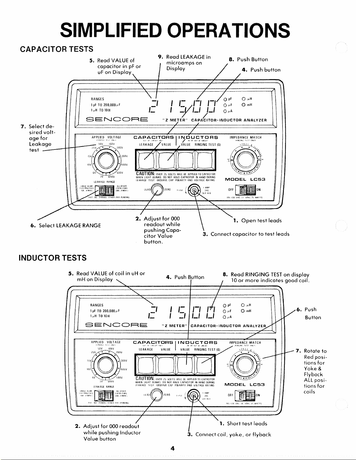
CAPA C IT OR TESTS
7. Select de
sir e d volt
ag e for
Le a k a ge
test
5. Read VALUE of
ca p aci t o r in pF o r
uF on D isp l a y
9. Read LEAKAGE in
mi c r o a mps on
8. Pu sh But to n
4. Push b u t to n
6
. S e le c t LEAKAGE RANGE
INDUC TOR TESTS
5. Read VALUE of co il in uH or
mH on Dis play
r,
2. Adj ust fo r 000
rea dou t wh i l e
pu sh ing Capa
c i t or Val u e
b u t t on.
4. Push Bu tt on
1. Ope n t e st leads
3. Connec t cap ac i t or t o test l eads
8. Read RIN G IN G TEST on d is pla y
10 o r mor e i n d i c a tes g o o d co il.
6
. Push
Button
7. Rotate t o
Red pos i
tions f or
Yoke &
Flyback
ALL p osi
tions f or
coils
2. Ad ju s t f or 000 re adout
w hil e p u s h in g I n d u c t o r
Val u e but ton
1. Short test lea ds
3. Conne ct coil, yok e , o r f l y ba ck
Page 5

Not es
5
Page 6
DE SC RI PT IO N
INTRODUCTION
The use of capac itors in electronics ha s d ramat ic all y
increas ed in t he p as t few y ea rs and t he for e ca st is for
even a g re a te r usage. The t ra n si st o r has g i v en wa y to
the IC, b u t due to t he n at ur e and c o n s tr uc t io n of the
cap ac ito r an d th e inductor, t hes e are n o t re pl ac ed with
ICs. The more ICs t h at are use d, the mo re ca pa ci tor s
and in du cto rs t h at will be used. The tol era nc e of the
capa cit or used to be 20%, b u t today, y o u will find
circu it s h av ing 5% to lerance capa cito rs as s tan d ar d.
The use of ele ctrolytic c apa cito rs has als o d ra stic all y
increased as well as the capaci ty range. Lyti cs of
10,000 uF can be found in m an y c on su m e r electronic
items. Now more t h an ever, the need to measure
cap ac ity value, leakage of the capacitor, i n d u ct o r value
and q ua li ty of the in duc tor has become v er y impor
ta n t. W i th ou t a good measur e of these i mpo r t a nt pa ra
me t e r s, pr o pe r ci r c u i t o p e r a t i o n b e comes m o re
difficult. Sencore has met the challenge head -on with
its all new, a u to ra ng in g “ Z ME T ER”, t h e LC53. Now
cap aci to rs can be checked for value a nd fo r l eak ag e a t
th e r at e d w o rk ing vol ta ge on a d i gi tal r ea d o ut .
Ind u ct o rs can be checked for induc ta nc e a nd for
qua li ty wi th the p a te nt e d Sencore rin g i ng test. The
LC53 is tru l y the firs t co mplete ca pac itor a n d in du cto r
analyzer.
FEATURES
SPECIF IC A TIO NS
DIGITAL RE A D O U T
TYPE: .5 ” , 7 seg m e n t LED .
ACCURACY: F un c ti o n accuracy ± resol utio n error .
RE S OL U T IO N : 3 sig n ific ant di gi ts ±2 cou nts on 3rd
digit (3Vi d ig i ts on capaci tor s of 100,000 uF to
200,000 uF).
A UT OR ANGING: Ful ly a ut omat i c d e ci mal
placement. On e o r two place holding zeros a d d e d as
needed (does n ot affect accuracy) to provide st a n d ar d
value read o u t s of uF, pF, u H, or mH .
RAN G E IN D IC A T O RS :
Type: LE D .
Operation: C ontr olled by t he au to r an g in g circui ts .
CAPAC IT ORS (O u t of Circuit):
Dynamic t e s t of capa ci ty value dete rm ine d by me a s ur
ing one RC tim e co n s ta n t when ca paci tor is ch a r ge d to
+5V through :
10 Megohm s for 0-9000 pF.
10 Kilohms for 9000 pF-90 uF.
100 Ohms for 90-199,900 uF.
ACCURACY: ±1% of re adi ng + re solu tion erro r.
±5% of re a d in g + resolutio n err or for c a ps over
1000 uF.
RAN GE : 1.0 pF to 199,900 uF in 10 a ut oma tic a ll y
selected ran ge s.
The Sencore LC53 “Z METER” f e a tu r e s adva nce d
Digi tal Logic circuits t h a t provide a u t o r a n g in g of the
me te r when checking the values of c ap a c it y or ind uc
tance. Si mply hook u p the c apac itor o r th e inductor,
pre ss the prop er VA L UE bu tto n, and re ad t h e value on
the large dig ital readout.
The “Z METER” also checks c ap aci to rs for leakage
wit h two selectable cur re nt range s at the r ate d
work ing volta ge from 3 Volts to 600 Vo lts. An L ED
(located b etw een th e L E A K A G E bu t t on and the
A P PLI ED V O LTA GE switch) will flash on an d off as
a safe ty rem in der when th e leakage t es t v o l ta ge is set
to 50 Volts or above.
Th e Sencore p a te n t ed rin g in g t e st c he c k s coils,
deflection yokes, a nd non-iron core t r a n sf o r m e r s with
an a c cu ra te c heck of good or bad. Th ere ar e six sw itch
selectable impedance m at ch in g po sit ion s t o m a t c h the
coil to th e t e s t circ uit from 10 u l i to 10 I I. Good coils
will show 10 or more rin gin g cycles on t h e d igit al d is
play while bad ones will show less than 10.
A special L E A D ZERO control lets you balance out
the cap aci ty or i nductan ce of the t es t lead s I'or those
acc u ra te readin gs of the very small capa ci to rs and
coils th a t you may encoun ter. The “ Z ME TER” is also
pro te cte d a ga i ns t accide ntal app licatio n of vo lta ge s to
the tes t leads by a front panel repla ceab le fuse an d a
special relay inside the inst rum e nt.
CAP ACIT O R LE AK A GE
ACCURACY: ± 5% 4- reso luti on error.
RANG ES : 0 to 99.9 uA an d 0 to 9.99K uA in two
switch selec tab le ranges.
VOLT AG ES : 12 s electable DC vo lta ges from 3 VDC
to 10 VDC filtered and from 1.5 VDC to 600 VDC,
non-filtered. Availabl e at t e s t leads only when
LE A KA GE pu s h b u t to n is depressed. Cap a ci to r is
aut om a tic al ly di sch arg ed when b ut t on is released.
IND U C T A NCE (In- or Out-of Circuit)
Pa te n t pe nd in g dyn am ic te s t of in du cta nce va lue
determ ined by m ea su ri ng t he E MF caused by a con
sta nt ly vary i n g cur re nt throu g h t he coil u n de r test .
Current ra t e s are:
10 mA/usec - 0 to 90 uli .
1 mA/usec - 90 to 900 uli
.1 mA/ usec - 900 ul i to 9 mH.
.01 mA/u sec - 9 t o 90 mil .
1 uA/usec - 90 to 900 m il .
.1 uA/usec - 900 to 9,990 m il .
ACCURACY: ±2 % of reading -*■ resolution error.
RANGES: 1.0 uli to 9,990 mil in 6 auto m a tic a ll y
selected range s.
6
Page 7
RINGING TEST
Dynamic te s t of inductor q u al ity d ete rmi ned by c ou n t
ing the number of cycles the in d u ct or rings before
reaching a p re se t dam pi ng po i n t af te r a given exc itin g
pulse has been applied. (US pat e nt 3,879,749).
ACC E S S O R I E S (Optional)
39G85 T ouch Te st P robe
GENE R A L
EX C IT I N G PUL SE AMPL I T U DE : App rox im atel y 7
Volts peak.
ACC UR AC Y : ± 1 c ount from r ea d i n g s of 8 to 13.
ACCES S OR IE S (S up plie d)
39 G 143 Te st Leads *
39G144 Te st Lead A da pt or
39G145 Test B u tt o n Hold Dow n Rod (2 supplied) '
64G37 Test Lead M o unt in g Clip
68G34 Allen Wrench
44G20 Spare 1 A m p Slo-Blo F u se
“Specifica tions su bje ct to cha ng e w it h o u t not ice.”
T E MPERAT URE RAN G E S (Typical): Calibr ated at
70 °F. Rated accuracy range: 50-90 °F, Opera ting
rang e: 32-130°F.
PO W E R: 105-130 VAC, 60 Hz, 25 Wa tt s .
T E S T L E A D INP UT: Fuse p r o te c te d with in-line 1
Am p 3AG Slo-Blo fuse.
SIZ E : 6” x 9” x 11.5” (15.24 cm x 22.86 cm x 29.21 cm)
W E I GH T: 7.75 lbs. (3.56 Kg).
Page 8
CONTROLS
1. Front panel digital readout, fi r s t th re e d igit s read
the value of capacity , inducta nce, l eak ag e curr en t or
ring ing test values, las t two di g it s are plac e holders
and only indicate 0 on larger va lue s of ca paci ty, ind uc
tance, or leakage c u rre nt so all rea di n gs are given as
pF, uF, uH, or mH.
2. a. Indic ato r LED, lights up when capa cito r re ad
ing is in picofarads (pF).
b. In dica tor LED, ligh ts up w hen capa cito r re ad
ing is in microfara ds (uF).
c. Indicator LE D, light s up wh en c ap acito r leak
age reading is in microamps (uA).
d. Indica tor LED, light s up wh en ind uct or rea d
ing is in m icrohe nrys (uH).
e. Indicator LED, lights up whe n i nd uct or r ea d
ing is in millih enrys (mH).
3. I M PE D A N C E MATCH s w itch , r o t a te d thro ug h
th e l as t 4 t es t po sitio ns when m a k i ng the r in gin g te s t
on yokes and flyba cks and thr o u gh all 6 positions
when te st ing ot her induct ors. A r e a d in g of 10 or more
indi ca tes a good inductor.
4. Power ON-OFF switch, co n tro ls th e AC line vol
tag e to the “Z M ET E R”.
13. LE A KA G E RA NG E switch, us ed to se lec t the
desired range of capacitor leakage current, 0 to 100 u A
or 10K uA .
14. APPLI ED VOLT AG E SWIT CH , used for
selecti n g the desired test v olta g e when ma kin g capaci
tor leakag e tes t s.
REA R PANE L
15. Rear panel meter zero adjust. A d just to zero
digital readout with all buttons out.
16. 39G145 T es t Button Hold Down Rod mounting
clip.
17. 39G144 Test Lead Ad aptor mou nt ing clip.
18. Cord wrapper for stori ng AC line cord and t es t
leads.
5. RINGIN G TE S T pushb utto n, depre sse d when
ma ki n g the p a te n te d Sencore rin g in g t e s t on induc
tors , yokes, an d flybacks to check the quality. Use
IM P E D AN C E M ATC H switch (3).
6. Tes t Lead Input jack. U nscre w j ac k for access to
in p u t protectio n fuse.
7. Inductor VALUE push bu tton , d ep ress ed when
te s ti n g induct ors for value of induct anc e.
8. Capacitor VA L U E p u s h b u tt o n , de pre ss ed when
tes t i n g capacitors for capac ity value.
9. Leakage chart on pull out.
10. LEAD ZERO adjust, u sed to balance ou t the
small value of capac ity or in d uc tan ce in t h e t e s t leads
when maki ng precise m ea su re m en ts of s mall v alues of
cap a ci ty or inductance.
11. LE A KA GE test pu shb utton, depress ed when
te s ti n g capa citors for leakage a f te r t he AP PL I ED
VO LT A G E switch (14) has been set to th e wor king vol
tag e of t he c apac itor a nd L EA KAG E RA N GE switch
(13) is s et to th e pr ope r value as i nd ic a te d in th e leak
age c h a rt (9).
12. Cautio n ind ic at o r LED, bl i n k s when the
A PP LI ED VO LTA GE switch (14) is se t to 50 Volts or
hig her as a warn ing to th e user. Vol ta ge is only pres en t
on te st leads when L EAKAGE b u tt o n (11) is
depres sed .
8
Page 9
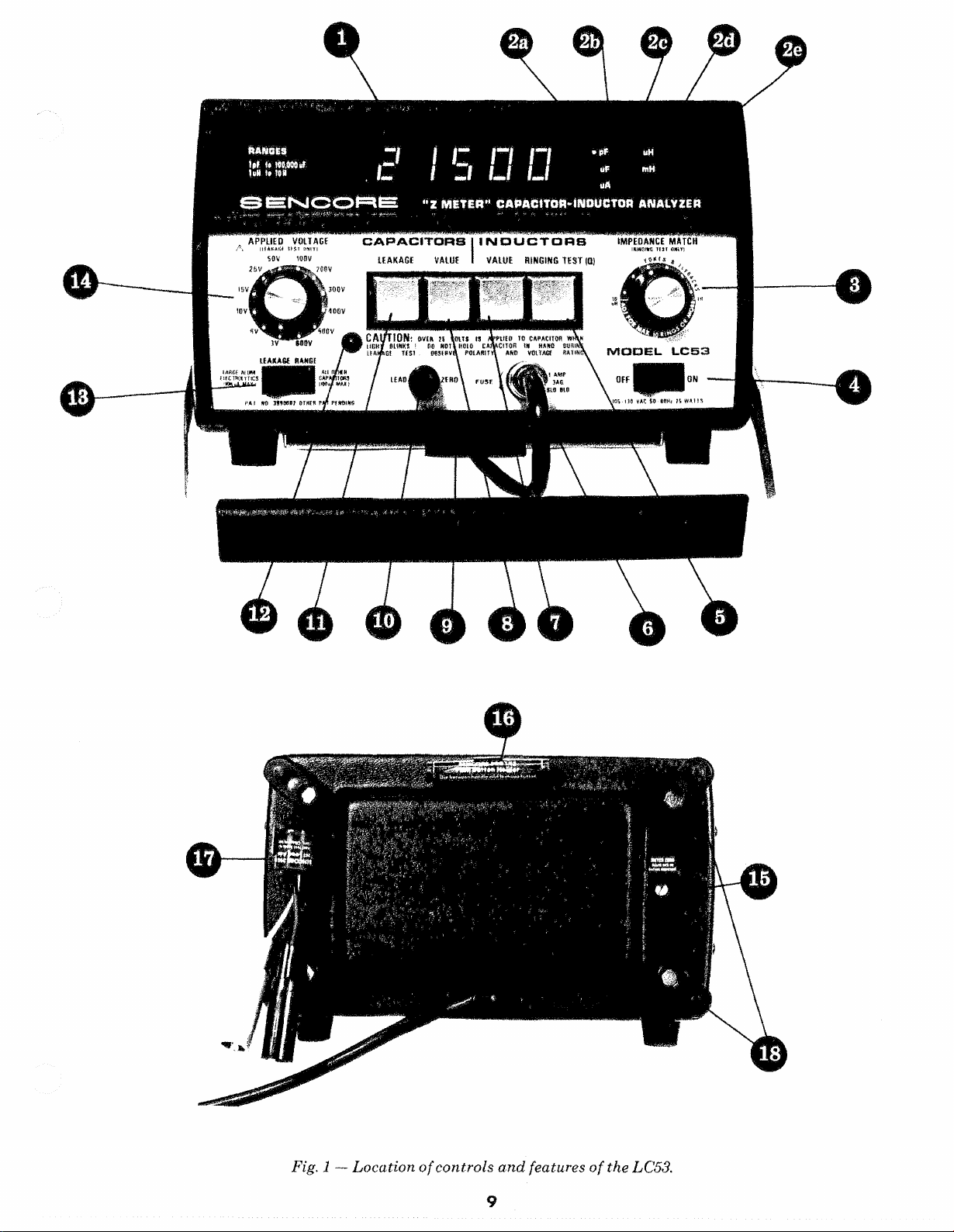
Fig. 1 — Loc a t io n o f c on t ro ls a nd feature s of the LC53.
9
Page 10
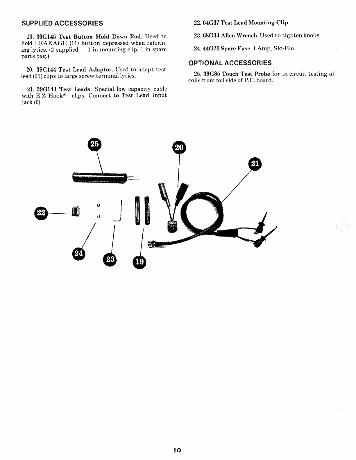
SUPPLIED ACCESSORI E S
22. 64G37 Tes t Le ad Mo un tin g Clip.
19. 39G145 Te s t Bu t t on Hold Down Rod. U sed to
hold L E AKA GE (11) but t o n d epres sed when ref or m
ing lytics. (2 s up plie d — 1 in m ou n tin g clip, 1 in spare
par ts bag.)
20. 39G144 T e s t Lead A da p t o r, Used to a d ap t t es t
lead (21) clips to large screw term ina l lytics.
21. 39G143 Te s t Leads. Special low capa city cable
with E-Z Hook® clips. Co nn e ct to T es t Lead Inpu t
jack (6).
23 . 68G34 Allen Wrench. Used to t ig h t e n knobs.
24. 44G20 Spare Fuse . 1 Amp, Slo-Blo.
OPT IO N A L A CC ES SO R IES
25. 39G85 Touch Te s t Probe for in-circuit t es ti n g of
coils from foil side of P.C. board.
Page 11

Not es
Page 12
OP ER AT IO N
INTR OD U CT IO N
Before usin g y o u r LC53 “Z ME TER” for the fir st
time, take a few min u t e s to read thr ou gh the o pe ra
tions an d ap p li ca ti on s s ectio n of t he manu al carefully
to ac q u a in t y o ur se lf w it h the featu res of th e LC53.
Once you are familiar w it h the general operation s,
m os t t e s t s can be p erf or me d with the info rma tion p ro
vided on t h e LC53 fro n t panel.
POW E R CO NN EC TION
The LC53 is design ed to be op erate d from 105-130
VAC (50/60 Hz). If 210-230 VAC operatio n is required,
the un it m ay be modifie d (at additi onal cost) by t h e
Sencore Service De pa r tme n t, 3200 Sencore Drive,
Sioux F alls , SD 57107.
To ope ra t e th e LC53 from t he AC line:
1. Co nn ec t t h e AC line cord to a 117 VAC (or 220
VAC for modified uni ts) outl et.
2. T u r n t he power sw it ch on.
3. The LC53 is im m ed ia tel y rea dy to mea sure ca p a
city or ind uc tan ce . If prec ise m ea su re me nt s are to be
made, th e u ni t sh ould be allowed to opera te for at l ea st
5 m i nu t e s to allow th e cir cu its to stabilize.
BLOW N FUS E CON D I T I O N S
FU S E
Test
Lead
Inp u t
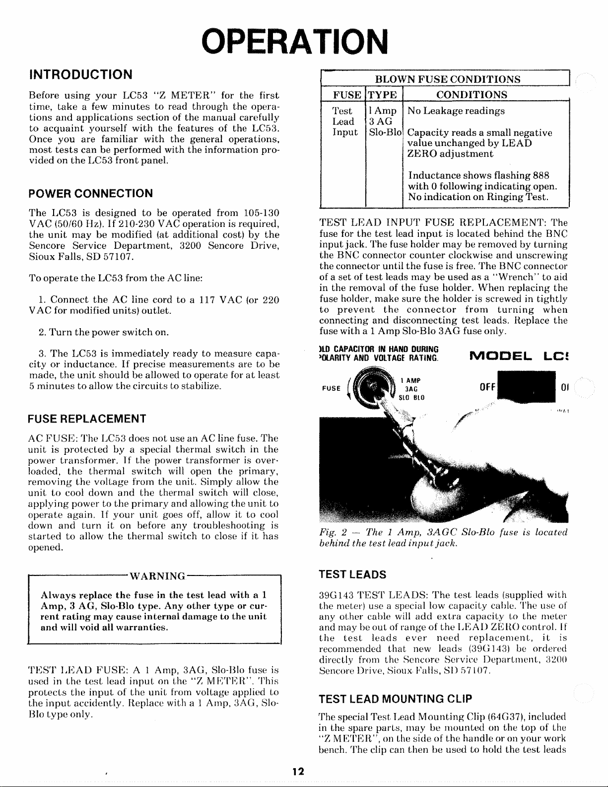
TE S T L E AD INP U T F USE RE P L A C E ME N T: The
fuse for the te s t lead i n pu t is lo cat ed behind the BNC
input jack. The fuse holder ma y be removed by tu rni ng
the BNC connecto r c o u n te r clockwise a nd u nscre wing
the connector until t h e fu se is free. The BNC connector
of a s et of test leads ma y b e us ed a s a “ W re n ch ” to aid
in the removal of th e fuse holder. W hen r eplacing the
fuse holder, m ake sure t h e holder is screwed in t igh tly
to pr ev en t t h e c onnect or fr o m tur ni ng wh en
connecting an d d is co nn ec ti ng t e s t leads. Replace the
fuse w ith a 1 A mp Slo-Blo 3 AG fuse only.
)L Q CAP ACITOR tU HA ND DURIN G
>0 L ARITY AND VOL TAGE RATIN G .
FUSE
TY P E CO ND I T I O N S
1 Amp
3 AG
Slo-Blo
No Lea k ag e rea di ng s
Ca p ac i ty re ad s a sma ll neg ative
valu e un c h an g ed b y L E AD
ZE R O a dj u s t me nt
In d u ct a n ce sh ow s fla shing 888
wi th 0 following ind ic ati ng open.
No indica ti o n on Rin g ing Test.
M O OE L LCJ
FUSE RE P L ACE MEN T
AC FUS E : T he LC53 does n ot use an AC line fuse. Th e
unit is pr o te c te d by a special th erm al sw itch in the
power tra ns fo rmer . If th e power tran sf or m er is o v er
loaded, the ther m a l sw itc h will open the prim a ry,
rem ov in g t he vol tag e from the unit. Simply allow th e
unit to cool down a nd the ther mal switch will close,
app ly i ng powe r to t he p ri m a ry and allowing the un i t to
ope ra te ag ain. If y o ur u n it goes off, allow it to cool
down and tur n it on before any troubl es hoo tin g is
st a r te d to allow the th er m a l switch to close if it h as
opened.
WAR N I N G
Alw a ys re pla ce t h e f use in th e t e s t lead with a 1
Amp , 3 AG, Slo-Blo ty pe. Any o th er ty p e or c ur
ren t ra t i n g m ay c au se in te rn al dam age to the un it
and will void all warr an ti es .
TES T L E AD F U S E : A 1 Amp, 3 AG, Slo-Blo fuse is
used in the te st lead inp u t on the “ Z M ETER”. Th is
pr o te c t s th e in p ut of the uni t from voltag e applied to
the i n p u t ac cid entl y. Replace with a 1 Amp, 3 AG, Slo-
Blo ty p e only.
Fig. 2 — The 1 Amp , S AGC Slo-Blo fuse is located
behind th e t e s t lead inp ut ja c k.
TEST LEADS
39G1.43 T E S T LE AD S: The t e s t leads (supplied with
the meter) use a special low c ap aci ty cable. The use of
any oth er cable will add e x tr a ca pa city to the meter
and may be out of range of th e L E A D ZE RO control. If
the t e st le a d s ev e r n e e d re p l ac ement , it is
recommended th at new leads (39G143) be ordered
directly from the Senc ore Service De pa rt me nt , 3200
Sencore Drive, Sioux- Falls, SI) 57 107.
TEST LEAD M O U NTI N G CLIP
The special Tes t Lead M o u n ti n g Clip (64G37), included
in th e sp are pa rts , m ay be mo u nt ed on the top of the
“Z M ETE R”, on the side of the han dle or on you r work
bench. The clip can th en be us ed to hold th e t es t leads
12
Page 13
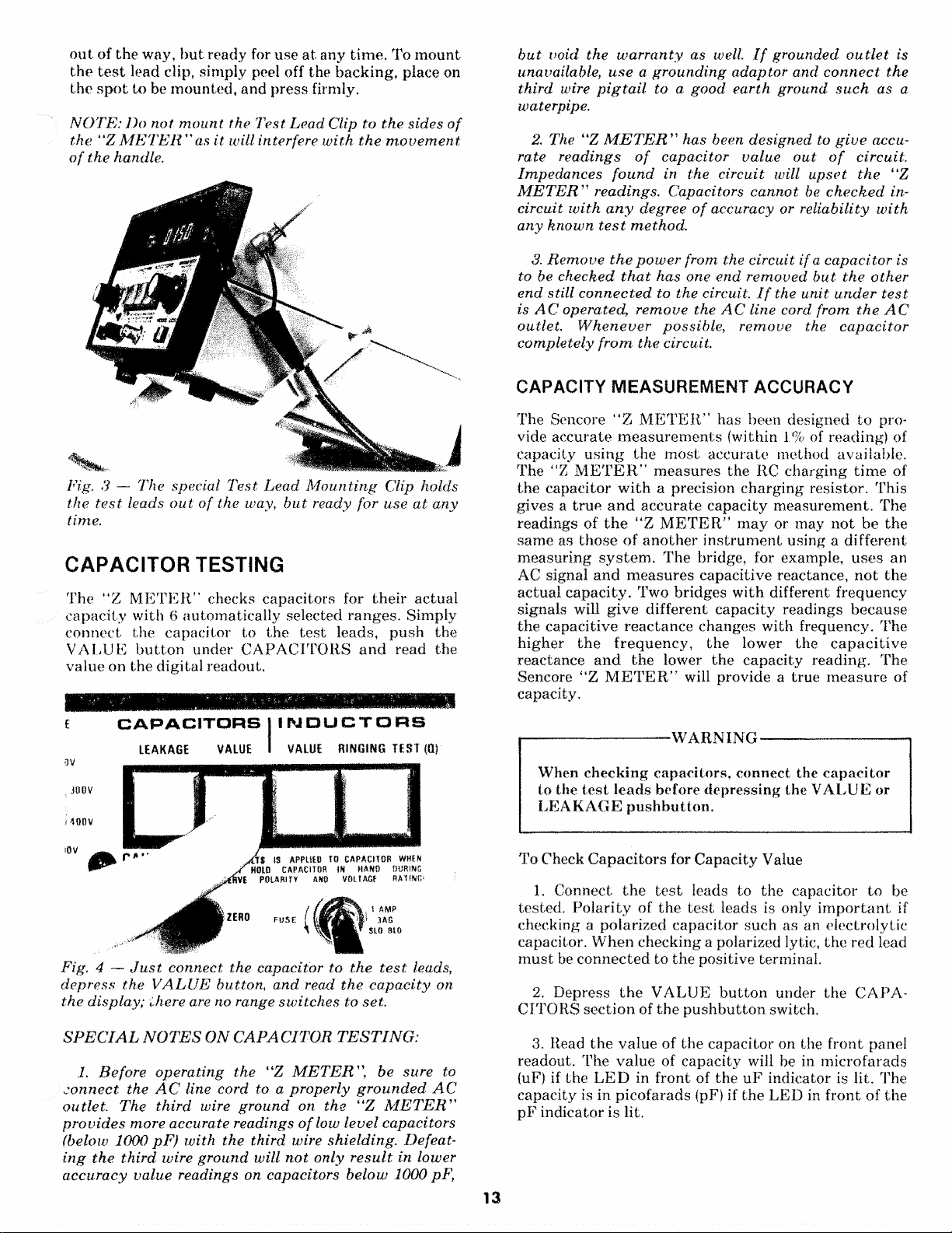
out of the way, b u t ready for use a t any tim e. To m ou nt
the t e s t lead clip, simply peel off the ba ck in g , place on
the s p o t to be mounte d, and p res s firmly.
NOT E: Do not mo u n t the T e s t L ea d Clip to t h e sid es o f
the “ Z M E TER" as it will interfere w i th t h e mov eme n t
o f the handle.
Fig, 3 — Th e special T e s t Le a d Mo u nt i n g Clip holds
the t e s t leads o ut of th e way, bu t ready fo r use at a n y
time.
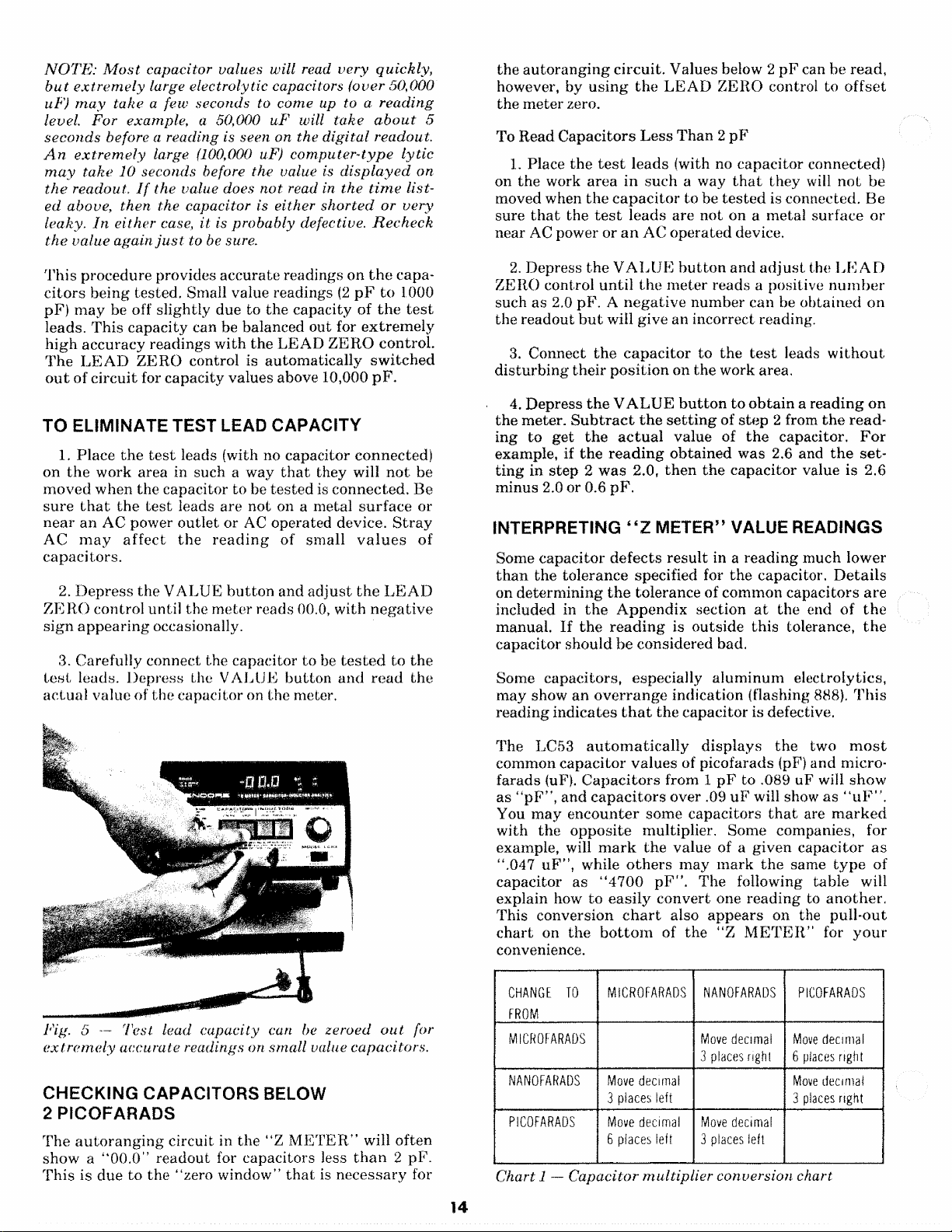
CAP A CIT O R TESTING
The “Z M ETER ” checks cap aci tors for th eir actual
cap a ci ty with 6 au tom a tica lly selected ra ng es . Simply
con ne ct the capacito r to the tes t leads, pu sh the
VA L U E b u tt o n under CAPA C IT O R S an d read the
value on the d igit al read out.
bu t void th e wa r r a n t y as well. I f grounded, out let is
unavailable, us e a g r o u n d in g a d ap to r a nd c o n n ect the
third wire pi gt ai l to a go od ea rt h gro un d suc h as a
waterpipe.
2. The “Z METER ” has been d es i gn e d to give accu
rate re a d in g s of cap a ci to r v a lue o ut of circuit.
Im p ed a n c e s f ou nd in the circu it will up s e t the “Z
MET ER'’'1 rea din gs. Capacitors c a n n o t be checke d in-
circuit wi t h any degree o f accuracy or re liab ili ty w it h
any k n o w n te st m et h od .
3. Re mo v e t he powe r from the cir cui t if a cap ac it o r is
to be c he ck ed t hat has one en d re mov e d bu t t h e oth er
end stil l c o n n e c t e d to the circuit. I f the un it u n d e r te s t
is AC oper ated , r e m o ve the AC line cord from t h e AC
outlet . W he n ev er poss ib le , r e m o v e the c a p ac i to r
com pl et el y f r o m th e circuit.
CAP A C IT Y MEA S U R E M E N T ACC U RA C Y
The Sencore “Z ME TE R” has been designed to p ro
vide acc ur ate me a su r em e n ts (within 1% of reading) of
capacity usin g the mo st accura te method available.
The “Z ME TER” me asu re s the RC c ha rgin g time of
the capacito r w i t h a precision c ha rgi ng resisto r. This
gives a t r ue a nd ac cu ra te c ap ac ity me asu rem en t. The
readi ngs of the ‘‘Z METE R” m ay or may no t be the
same as tho se of a n o th er i n st ru m e n t using a dif fe ren t
meas ur ing sy st em. Th e bridge, for example, use s an
AC signal a n d mea s ur es capac itiv e reactan ce, no t the
actua l c ap aci ty . Two b ridge s wit h different frequ enc y
signals will giv e different ca pac ity readings b ecau se
the capaci tive reac ta nc e c hang es with frequency. The
hig he r the freq u e nc y , the lower th e cap a c i ti v e
reactanc e a n d the lower the capa city readi ng. The
Sencore “ Z ME TER” will pr ovide a true me as u re of
capacity.
E
3V
; JOOV
/ 490V
10V
CAPACITORS I INDUCTORS
LEAK AGE VALU E I VA LUE R INGI NG T E ST (0}
Fig. 4 — Jus t co nn e ct th e capac itor to the t e st leads,
dep re s s th e VAL UE b utt o n, and read th e ca p a c it y on
the d isp la y; the re are no range switc h e s to set.
S PECIAL NOTES ON C APA CIT OR TESTING:
1. Be f o re op e ra ti n g t he “Z M E TE R ”, be sure to
co n n e ct th e AC line cord to a p r op er ly g r ou n de d AC
outl et . The third wire g r o u n d on the “Z ME T E R ”
pr o v i d e s mor e accurat e rea ding s of low le ve l capacito rs
(below 1000 pF) w i th the third wire s hie l di ng . Defea t
ing th e t h ir d wire gr o u nd will n o t only re su l t in lower
acc u ra cy value read ings on capacito rs belo w 1000 pF,
-WA R N IN G
When ch ec kin g c ap acitor s, conn ect the ca pa ci to r
to the te st le ads before d ep ress ing the V A L U E or
LE A K AG E p u s h bu t to n .
To Check Capa ci to r s for Capacity Value
1.. Connect t h e t e s t leads to the capacitor to be
tested. P ol a rit y of t he t e s t leads is only imp o r ta n t if
checking a polar ized capa cito r such as an ele ctrol ytic
capacitor. W h en checki ng a polarized lytic, the red lead
mu st be con n ect ed to th e posit ive terminal.
2. Depress the VAL U E bu t to n under the CA PA
CITO RS se ctio n of the pu s h b u tt o n switch.
3. Read th e v al ue of the cap aci tor on the f ron t panel
readout. The va lu e of ca pa cit y will be in m ic rof ara ds
(uF) if the L E D in f ro nt of the u F indica tor is lit. The
capacity is in picof ara ds (pF) if the LE D in fron t of th e
pF indic ator is lit.
13
Page 14
NOTE: Mo s t capa cito r values will read v e r y qu ic k ly ,
but e xtr e me l y large electr olytic capacitors (ove r 50,000
uP) m a y take a f ew seco?ids to come up to a r e ad in g
level. For example, a 50,000 uF will tak e abou t 5
se co n d s before a reading is seen on the d i gi ta l readou t.
An extr em ely large (100,000 uF) co m p ut e r -t y pe lyti c
m ay ta k e 10 secon ds before the value is d i s p l ay e d on
th e readout. If the value does no t read in th e ti me list
ed abov e, then the capacitor is either s h or t e d or v ery
leaky. In eith er case, it is p ro ba bl y defective. Rec h e c k
th e v alu e ag ain jus t to be sure.
the aut or a n gi ng circ uit . Values below 2 pF can be read,
however, by us in g th e L EAD ZE RO control to o ffs et
the met er zero.
To Read Cap ac it or s Le ss Tha n 2 pF
1. Place t he t e st le ad s (with no c ap aci to r conne cted)
on t he work are a in such a way t hat th ey will no t be
moved when the cap ac it or to be test ed is connected. Be
sure t ha t the t e s t leads are not on a m etal surf ace or
near AC power or an AC oper ate d device.
Th is pro cedu re pr ovides ac cur ate readings on t h e c ap a
cit or s being test ed. Small value readings (2 p F to 1000
pF) m a y be off sligh tly due to the capaci ty of t h e t e s t
leads. T his ca pac ity can be ba lance d out for ex tr em e ly
hig h ac cur acy r ead ing s wit h t he LE A D ZE R O co ntr ol.
The L E A D Z ER O control is auto ma tica lly switc h ed
out of circu it for capacity values above 10,000 pF.
TO ELIMINA T E TES T LEAD CAPA C IT Y
1. P lace t he te s t leads (with no capaci tor con necte d)
on th e work area in such a way t h a t they will no t be
moved when the c apac itor to be teste d is conn ect ed. Be
sure tha t the t e st leads are not on a met al s ur fa c e or
nea r an AC power o utle t or AC operated device. St r ay
AC ma y aff e c t the r e a d i n g of small v a l u e s of
capa ci tor s.
2. D ep re ss th e VA LU E bu t to n and ad ju s t t h e L EAD
ZE R O control un til the me ter reads 00.0, with n eg a ti ve
sign a p pe ar in g occasionally.
3. Ca refully connect the capa citor to be t e s te d to the
Lest leads. D epre ss the VALU E b ut ton an d re a d the
act ua l value of the capacitor on the meter.
2. Depre ss th e V A L U E b u t t on and a d j u s t the L E AD
ZERO control u nt il t he m et er read s a positive n u m b er
such as 2.0 pF. A n eg a ti ve nu m ber can be obt ain ed on
the reado ut b u t will give an incorrect reading.
3. Connect the c a pa ci to r to th e t e s t leads wi th o u t
dist ur b in g the ir p os iti on on the work area.
4. D epr ess th e VA L UE b ut to n to obta in a read ing on
the meter. S ub t r a c t t h e se tt in g of ste p 2 from th e r e a d
ing to get the actu a l value of t h e capacitor. F o r
example, if t he re a d in g o bt ain ed wa s 2.6 and the se t
ting in s tep 2 was 2.0, t h en the ca pa ci tor value is 2.6
minus 2.0 or 0.6 pF .
INTERPRETING “ Z METER” VALUE READINGS
Some capac ito r d ef ec ts r esu lt in a r ea di ng much lower
th a n the tole ranc e specified for t he capacitor. D et ai ls
on determ inin g t h e to leranc e of common capa cito rs a re
included in th e Appe nd ix section at the end of t he
manual. If th e rea d i ng is outsi de this tolerance, the
capacito r sho uld be consider ed bad.
Some capacito rs, especially aluminu m electrolytics,
may show an o v e rr a ng e indic ation (flashing 888). T h is
read ing indica tes that th e cap acito r is defective.
Fig. 5 Tes t lead capa cit y can be zeroed o u t for
ex t r em ely acc ura te readi ngs on sm all value capacitors.
CH E CKI N G CA P A C IT O R S BELOW
2 P I C OFA R A D S
The a u t o ra n g in g circuit in th e “ Z MET ER” will ofte n
show a “0 0 .0 ” r ea do ut for ca pacito rs less tha n 2 pF .
This is du e to the “zero win dow ” t h a t is ne ce ss ary for
The LC53 au to ma t i c a ll y dis pl ay s the two m o s t
common capa cit or va lue s of picofara ds (pF) and m ic ro
farads (uF). C a pa c it or s from 1 p F to .089 uF will show
as “ pF” , a nd c a p ac i to rs over .09 uF will show as “uF” .
You m ay en c ou n te r s ome capa cito rs t h a t are m ar k e d
with the op po sit e multiplier. Some companies, for
example, will m a r k the value of a gi ven c apa cito r as
“.047 uFM, while ot h er s may m ar k the same t yp e of
capac ito r as “ 4700 p F " . Th e following table will
explain how to ea sil y conv ert one rea din g to an o th er .
This conversion ch a r t also appe ar s on the pull-o ut
cha r t on th e bo t t o m of the “Z M E TER ” for you r
convenience.
CHANGE TO
FROM
MICROFARAD S
NANOFARADS Mov e de c i ma l
PICOFARADS Move d e c i m a l
MIC RO FAR ADS NANOFARA DS PICOFARADS
3 pla c es lef t
6 pla c es lef t
Move d ec i ma l
3 pla ce s r i gh t
Move d ec i m a l
3 pl ac es le f t
Move d e c i m al
6 places r ig h t
Move de c i mal
3 places r ig h t
Chart 1 — Ca pa cito r mul ti pl ie r conver sio n chart
14
Page 15
TESTING LARGE SCREW T ERMIN A L LYTI CS
Some lytics, especially in in d us tr ia l ap plic atio ns, use
rat he r large screw terminals rat h er than the conven
tional solder terminals. The 39(1144 TES T LEA D
Ada p to r (supplied with the LC53) should be used to
con ve rt the small E-Z 1 look “ clips to large alligato r
clips to fit the large screw te rmin als . A special clip is
moun ted on the back of the LC53 to s to re the 39 GI4 4
when it's not in use.
Fig. 6 — The 39G144 Tes t L e ad a d a ptor allows even
the large screw te rm in a l ca pacito rs t o be co n ne ct ed to
the LC53 for testing.
To Use the 39G144:
1. Connect the Red E-Z Hook" on the LC53 te s t
leads to the red term inal of the 39G14 4 T ES T L E A D
ADAP TO R. Co nnect t he Black clip to the other
terminal.
2. Connect th e Red alligator clip of the 39G.144 to the
posit ive screw term inal and th e Bla ck all iga tor clip to
the n egativ e termina l.
3. Tes t the cap aci tor in the u su al m an ner .
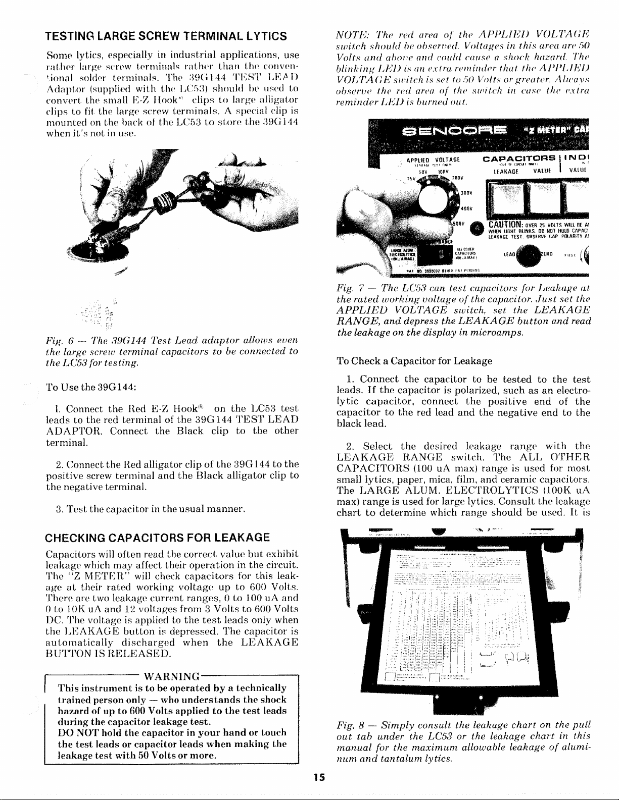
NO T E: The red area, o f the APP LIED VOLTA GE
sw it c h s ho u ld be observed. Voltages in this area are 50
Volts an d above and could cause a shock hazard. The
blin k i ng L ED is an extr a r emin d er th at the APPL I ED
V OL TAGE switc h is set to 50 Volts or greater. A l w a y s
obse rv e the red area o f the sw i tc h in case the extr a
remi n de r L ED is burned out.
Fig. 7 —- T he LC 53 can te st ca pacitors for L e ak a ge at
the ra t e d w o r ki ng volta ge of the capacitor. Just set, the
APPLIED V OL TA GE swit ch, set the LEAKAG E
R ANGE , a n d dep ress the LEA KAGE b u t t o n an d read
the leak a ge on the displ ay in microamps .
To Check a Capacitor for Leakage
1. Conne ct the capac itor to be test ed to the test
leads. I f th e c apacit or is polarized, such as an e lectro
lytic cap a ci to r , c on ne ct the p o si ti ve en d of the
cap ac ito r to t he red lead a nd t he neg at iv e end to the
black lead.
2. Se lec t t he desired leakage rang e with the
LEAKA GE R A NG E switch. The AL L OT H E R
CA P A C IT O R S (100 uA max) range is used for mo st
small ly tics, paper, mica, film, and ceramic capacitors.
The L A RG E ALUM. ELE CT R O LY T IC S (100K uA
max) ra n ge is used for large lytics. Consult th e leakage
ch ar t t o d eterm ine which range should be used. It is
CHECK ING CA PA C IT O R S FOR LEA K AG E
Capa cit ors will often read the co r re ct value b u t e xhibit
leakage which may affect th eir op e ra tio n in th e circuit.
The “Z MET ER” will check cap a ci to rs for this leak
age a t their ra ted working volt ag e up to 600 Volts.
Ther e are two leakage c urr en t ra n ge s , 0 to 100 uA and
0 to 10K uA and 12 vo ltage s from 3 Vo lts to 600 Volts
DC. The volta ge is applied to th e t es t le ads only when
the LE A KA G E bu t to n is depre sse d. The cap aci tor is
au t oma t i c a l l y d i sc h a r g e d w he n th e LEAKA GE
BUT TO N IS RE L EA S ED .
|
---------------------------
1 This in st ru m en t is to be opera ted by a technically
trained p erson only — who und e rs t a n d s the shock
hazard of up to 600 Volts applied to th e t es t leads
during the capac ito r leakage test.
DO NOT hold the capacitor in you r h an d or touch
the tes t leads or capacit or leads whe n m akin g the
leakage tes t with 50 Volts or more.
W ARNI N G
------------------------------
Fig . 8 — Si mp l y c on su lt the leakage ch a rt on the pu ll
ou t ta b unde r the LC 53 or the leaka ge ch a r t in this
man u a l for the ma x i m u m allowable leak ag e of a l um i
num a n d t an t al u m lytics.
15
Page 16

bes t to s t a r t with the hi gh est range (Large Aluminum
Electro lytic s) if you are not sure which r an ge to use. If
the display shows “000", then s w it ch to the other
rang e. You can switch ran ges of the L E A K AG E
RA N G E switch while holding the L EAK AGE bu tto n
in if you have selected the wr ong ran ge or merely wish
to sw itch ranges.
3. Select the normal DC working vo l ta g e of the ca pa
cit or to be tested w ith the A PPLI ED VOLTA G E
switch . If the normal wo rking v oltag e of th e ca pacito r
falls between the range s on the switc h, select the nex t
low e r range. For example, if the wo rk in g vol tag e of the
ca pa c it or to be test ed is 35 Volts, s ele ct th e 25 Volt
pos it io n of the APPL I ED VO LT A GE switc h.
4. Depress the L E A K A G E bu tt o n and read the
valu e of leakage cu rr ent in m icroamps on the display.
Cap ac it or s will take a specific a m o u n t of time to
cha r ge and give an a ccu ra te reading of th e leakage
cur re nt . Consult t he typ e of ca pacito r you are t es tin g
in the following listing for time require d to show a
display.
CER AM I C, PAPER, M ICA, AND FILM TY P ES:
Us e the ALL OT H ER CA P AC I TO R S posit io n of the
L E AKAGE R ANG E switch when t e s t in g t hes e c ap a
cit or s for leakage. The leakage r ea d i n g should take
only 2 to 3 seconds for an a ccu ra te dis pla y. In some
case s, w ith a very large value of c ap ac ity , a low leakage
re ad i n g may appear in the first second o r two and th en
cha n g e to 00.0. This is a normal cond itio n and merely
sho w s the capacitor is charging . If a re ad in g is still
pr e s en t after about five seconds, the cap ac ito r has
exces siv e leakage and should be conside red defective.
circuits. Wh en a lytic is fully ch arged, th e rea d in g will
change in small st ep s up and down showi ng th e ca p a
citor is charg ed . T he se small step s s impl y in di ca te t h a t
the c a p ac i to r und er tes t is a t te mp t in g t o filter small
changes in th e AC power line voltage. I t is not neces
sary, in mo s t ca ses, to wai t un til t he ca p ac it o r is fully
charged to de ter m ine if it is good. Just d e p re ss the
LE AKA GE b u t t o n until the leakage d ro ps below the
max im um allo wable level as shown on t he c h a r t in the
manu al or o n the pull out table on the bo t t o m of the “ Z
M ETER”.
If th e LAR GE ALUM . EL E C T RO L Y T IC (L0K uA
max) r an g e is used first a nd the rea din g d r o p s to 000,
simply c h an g e t he L E A K A G E RAN G E s w it ch to the
ALL OTH ER C A PA C IT OR S (100 uA max) range
while de pr e ss i ng the LEA K A G E b ut to n. Ignore the
first tw o r e ad i ng s a ft er ch ang ing ra ng es a s the rang e
switch ing cha ng es the series imped ance which in tu rn
causes a m o m e nt ar y cha nge in the charg ing ra te .
130
S PECIAL NOTE O N L OW V OL TAGE C ER AMI CS :
Ceram ic capacitors of 50 wo rk in g vol ts or gre at er hav e
a ver y high insulation re sistan ce an d s ho u l d no t sh ow
a n y leakage on the lea kage test. Ceramic capacitors
w i t h a lower w o rki ng voltag e tha n 50 Vo lt s have a
m u ch lower i nsulat ion resi sta nc e a n d m ay shoiv lea k
age on the leakage test. The act ua l in su l a ti o n r esi s
tan c e va ries fro m m a n uf a ct ur e r to m an uf a ct ur e r, bu t a
gen e ra l rule o f th u m b is: 16 wo r ki ng vo lt capacitors
ma y sho w as muc h as 16 u A o f lea ka ge and be w it hi n
tolerance. 25 Volt ceramic capacit ors m ay show up to
2.5 u A of leakage. It is b es t to m a k e a com p a r is o n test,
i f po ss ib le, with a kn o w n g o od ca p a ci to r a n d the su s
p ect ca pacit or wh en in doub t I n most cases, t he se low
vo lt a g e capacitors will on l y be u s e d in circu its where
th is hig h leakage will not u p s e t th e cir c u it operation.
AL UM INU M LYTICS:
Th e alu min um lytic charg ing time will v a ry w ith t he
ca pa c it y and th e applied leakage vo ltag e. On larger
lytic s, the m eter will overra nge (showing flas hing 888)
un ti l the c hargin g cur re nt drops b elow 10 mA. The
ty pi ca l amo un t of time tha t the m et e r will o verr ange
can be determined from cha rt 2. The d ispl ay will
usu al ly begin a t a high leakage r ea d in g an d then drop
wi t h each u pda te of the digital di spla y. Th is show s the
c h argi ng ac ti o n of th e ca pa ci t or thr ough th e
imp ed an ce of the APP L I ED V O L TA G E power sup ply
Capacity (u F)
Chart 2 — Me t er overrange tim e ve rsus c ap ac it or value
and app li e d v olt a ge .
NO T E: S ome lyt i cs may sho w a good value reading
and a lo w l eak ag e reading a nd be a q u es t io n a b le co m
ponent. If th e value is rechecked a fte r the leak age is
chec ked an d the capacit y is lowe r than f i r st chec ke d
and b eg i n s to increase to wa rd the original value, the
lytic is e x hi b i t i n g dielectric abs orption. T h is ge ne rall y
occurs w h en the electrolite in the lyti c begin s to d ry
out. Th e capa c ito r does n ot c o m p le te ly d is ch a rg e and
the re sid u al volta g e reduces th e c h ar gin g time ma k i n g
the ca p ac it or appear to be a smalle r value. I f a capa
citor ex h i bi ts dielectric absorption, try r e fo r m i n g the
capacitor as ex p la in ed in “Ref o rmi n g Ly t ic s on the “Z
METER ” or ‘ Ref o rmin g L yti c s with a Po w er S u pp l y ”
covere d l a t e r in t hi s manual. I f the ly ti c stil l sh o w s
dielectric ab so r pt io n a fte r reforming, the l y t i c s h ou ld
be con si de r ed defect ive.
TANTALU M LYT IC S :
Ta n ta l u m ly tics have a much lower l eaka ge comp ared
to alum in u m lytic s for the sa me cap aci ty and working
voltage. T a n t al u m lytics should, in mo s t cases, be
checked on the AL L O TH E R C A P A C IT O R S r ang e of
the L EAKAG E RA NG E switch. T a n t al u m l ytics will
give a leak ag e rea di ng in a very s h or t peri od of time,
ju s t a ma t t e r of 2 to 5 seconds.
16
Page 17

LEAKAGE CHARTS
The following leakage c h a r t s ar e the s ame ch a rt s t h a t
you will find on the pull ou t t ra y on the LC53 *'Z
vIETER". They show the ma x imu m allowable leakage
of common lytics and t a nt a l u m lytics. Note t h a t these
figures are t he wors t case c on di tio ns as specified by
the Ele ctronics In du st ry As so ci at ion (El A) s ta n da r d s
ItS-345, and m an y lytics will show leakage values well
below these figures.
MA XIM UM A L LOWABLE LEA K AGE (in micro a mps)
Sta n d a r d Al uminu m Electr o l y tic Ca p a c it o r s Stand a rd T a ntal um Ca p acit ors
Capacity
in ijF
1,000
1,500 400
2,000 470
5,000 740
10,000 Ί
20,000 1470
50,000 1700
100,000 3300
200,000
3V
1
3
5
10 5
15
20 5
25 5
30
35 6
40 6
50 8
70 11
100
150
2"0
250
300 45
400 200
500 230
750 290
40
340
1040
4650 6600 8 500
15
22
30
1 0 V 1 5V
6V
5
5
5
5 5
5
5 5 5
5 5 8
5
5 8 13
10 15
6
13 20
8
5
9 15 25
10
18
12 20
15 25 40
20 35 190
30 50 230
45 230 280
200 270 330
230 300
250 330
290 38D 470
330 4 20
520 640
400
470 600 740
740 900
570
660 850
1040 1340
1470 1900 2320
2070 26 80 3290
2340 4 24 0 5200
4650 6000
50 V 10 0V
25 V
5
5
5 5
5
5 8
6 13
13 25 50 270
20 40
5Π
25
30 220 300 420
40
230 330 460
28
45 250 360 500
30
190
270 380
210 300 420
250 350 500
300 420 600 850
370 520 730
420 600
370
470 670
400
S20 730
660 850 1200 1700
520
670 950 1340 1900
820 1160
950 1340
1160 1640 2320
1040
1340 1900
1640
2120 3000
3000
424Θ
6000
4240
9500
6700
7350
9500
200 V
5
15 30
25 50
230
270
1040
850 1200
950 1340
1040 1470
1640 2320
1900 2680
3286
2700
4240
300 V
15 20
10
45 200 below
230 270
330
330
400 4 60
460 540
380
520 600
570 660
620
540
660 760
600
730 850
710
870 1000
1040 1200
1300 1470
1470
1640
1800
2Q8Q
2320
2450
Non-polarized lytics should be m ea s ur e d for leakage in
bo th directions. Make the leak a ge t es t, then reverse
the te st leads an d r e pe at the te s t. Some non-polarized
lytic s have one lead connec ted to the case. The
allowable leakage on these ty p es is twice t h a t of a
reg u la r lytic of the same cap aci ty a n d v olta ge r at in g in
bo t h directions.
400 V
380 3.3
700
1550 220
Capacity
in u F
1.5 and
2.2
4.7
6.8
10
15
22
33
47
68
100
150
330
470
680
3V 8V 1 0 V
ALL CAPA CITOR S IN
THI S A RE A SH OUL D
J>hUW IMU
L EA KAGE
1.5
2.5
1.5
2 3.5
1.5 3 5
2 4.5 7
14
22
10
20
3 6.5
5 10 15
7
10.5 20
15
20
1 5 V 25V 50 V
1.5
2 3.5
2 2.5
2.5 4 6
3.5
5.5 10
8.5
5
7.5 12 20
11 15
16
20
14
20
1.5
2
2.5
5
Use LARGE ALU M I
NUM ELECTROLYTICS
Use ALL OTHER
CAPACITORS Range
Range
Chart 3 — Max i mu m a llo w a b le lea kage for Al umi nu m and
IDENT IF Y IN G CA P AC ITOR TYPES
The capacito r ha s i ncreased in use tr em endo us ly in the
pa s t few yea rs. M any new type s and i mproved
versions are now in use. The following info rma tion is
orovided as a guide to aid in th e identif icatio n of the
,ype of cap ac ito r a nd its valu e. Th e color code ch a rt s
cover mo st of t he v ar ia tio n s t hat will be encou ntered.
There may be oth er s not cov ere d here an d in those
cases, c on su lt t he m a n u fa c t u re r of the eq ui pm e nt for
information.
Tan t a l um ly ti c s per El A sta n dar ds .
TANTA LU M LYTIC S :
Ta n t a lu m l ytic s are be ing f ou nd in m or e electronic cir
cui ts th a n ever before. Its low leakage curr e nt and
sma ll er phys ical size has m a de it a st a n d o u t for solid-
st a t e circuits. The tan t a l u m lyti c s can be m ade to
tigh t e r tolerances tha n alum in um lytics. Tan ta lu m s
are no t mark ed as such and th e sche m ati c generally
does n o t indica te t he lytic as a t a n talum . The ta n t al u m
lytic is smaller (abou t one-half or less) tha n t he same
ca pa c it y a nd voltage a lum i nu m lytic. The ta n ta lu m
17
Page 18

comes in m an y sizes and s ha p es as shown in figure 9.
Some use a color code like t ha t s h ow n in figure 9. No te
th a t the color coding can show the p ositi ve lead. Some
tan t al u m s are m ark ed with t h e v al ue a nd a + on the
posit ive lead. Oth e r t a n ta l u m s use th e shape of the
lead or a r ou nd in g of a corner to indic a te the p ositiv e
lead.
Typ i c a l Physical Sha pe s of
Commo n Ta n t a l u m C apaci t ors
FILM TYP E S:
The s e are th e h a r de s t to identify as t o t h e t yp e of film
bei ng used. The typ e of film is no t ge ne ral ly m ark ed
and i t could be any one of at leas t five t ype s. On these
cap ac it or s, you will have to cons ult t he ma n u f a ct u r e r ’s
service infor ma tion for t he co rrec t typ e. It shou ld be
no t e d t ha t a Mylar® ca pacito r is not a universal
rep la ce m en t for any film typ e cap ac ito r. Ea c h film has
diff e ren t cha rac te ris tic s a nd m u s t be r ep lace d wi th the
sa m e ty pe of film used in the circuit. T hi s is especially
tru e in t ho se a rea s of s che ma tics that are de sign ed as
“ S af e ty C riti ca l” .
TE S T I N G FOR DIELECTRIC A B SORPT I O N
Dielectri c abs or pt ion is the inab ili ty of a cap aci tor to
com ple te ly d ischa rge to zero. This is s o me ti m es called
“ba t t e r y a c ti o n ” or “c apa cito r me mo r y ” a n d is due to
the dielectric of th e c apac itor r e t a in i n g a c harg e. All
ca pa c it or s have some dielectric ab s or p t io n , b u t electr o
lytic ca pa ci tor s have th e hi gh est a mo u nt an d will often
affe c t cir cuit op er atio n if it b eco mes excessive. You
can c heck lytics for dielectric a b s o rp t io n d u r in g the
no rm a l t e s t for c ap aci tor value an d lea ka ge by simply
ree he ck ing th e valu e of th e ca p ac ito r a f te r the lea kage
te s t in th e following man ner.
Fig. 9 — T a n ta l u m lyt ics co m e i n all size s a nd shapes.
The m o s t co m mon shap es are s ho wn here for identifi~
catio n o f the pos i ti ve lead.
CE R AMIC DISCS:
The ceramic disc is well-known an d c an be identified by
its round sh ape and generally b r o w n color. Some cer a
mic discs come in different co lors such as blue and
green due to a different co a t i n g materi al on the
outside. M o st ceramic discs a re m a r ke d wit h the value
and the tolerance. T he m ost c o m m on wo rkin g vol tage
(500 Volts) is gene rally not m a r ke d , b u t a n yth in g dif
ferent is normally found on t he cap ac i to r body. Th ere
are ot her marki ng s such a s NP O , GMV, N1500, or
similar. These a re th e t e mp e ra t u re coefficients or how
muc h the ca pa ci tor will ch a ng e with a change in
tem pe ra tu re. W he n repla cing a ce ram ic disc, be sure to
use the s ame ex a ct type t ha t w as use d in the original
circuit. NPO s t a n d s for Ne gativ e-Pos itive-Z ero or no
chang e in capaci ty. GMV is Guar a nt ee d Minimum
Value and th e a ctu al value could be muc h higher. Th e
let te r N in dicate s tha t the ca p a c i ty will decrease wit h
an increase in t em p er at ur e, an d if yo u find one w it h a
let te r P, t h a t one will incre ase in capacity with an
increase in tem p er at ur e. Fu r the r information will be
found in t he sectio n on “ C a p ac i to r Theory and th e ‘Z
METER’ ” a nd in the G lo s sa ry at the back of the
manual.
1. Co nne ct t he cap ac ito r to t he t e s t le ad s a n d t e st for
the c a pa ci tor value in the n ormal ma nn er . Note the
valu e of the capacitor.
2. T e s t the ca pac itor for l eakage a t t he ra te d work
ing v o lta g e of the capa citor. Allow t h e le aka ge c urr ent
sho w n on th e display to dro p to th e max i m um allow
able lea kage or below as shown on th e l eaka ge c h ar t in
the ma nu a l or on the pull out t ab u n de r t he meter.
3. Re lease t he L E A KA GE bu t t o n a n d allow th e d is
play to dro p to 000 and then i m m ed ia te ly depr es s the
VAL U E b u t t o n and note th e ca pa ci to r reading.
a. If th e c apa ci ty re ad ing is wi th in 5% of the origi
nal value and the re adi ng i nc re ase s slowly upward
tow a r d the original value, or th e re is no difference
in t h e r eading s, th e ca pacito r ha s v ery l ittle dielec
tric abs or pt ion and is good.
b. I f th e value re adi ng difference is gr ea t er th a n 5%
b u t less tha n 15%, the capa c it or m ay require
refo rm in g a s desc ribed later. So me of th e dielectric
oxide h as de te rio ra te d a nd r ef or m in g t he lytic m ay
br in g it back to a us eful life. R e ch eck for dielectric
abs or pt io n o ften a tt e m p t in g t o re for m t he capacitor.
c. If the valu e rea din g difference is gr ea t er than
15% and the rea din g c ha ng es u p w a rd rapidly
tow a rd th e origin al value, t h e ca p ac it or has exc es
sive dielectric ab sorp tio n. E le ct ro l yt ic capac itor s
exh ib iti ng t his much dielectric a b s o rp t io n may be
refor me d in some cases. If th e c a pa c ito r exhibi ts
simi lar dielectric abso rpt io n a f ter reform in g hai
been a tt e m p te d , it s hould be r epl ace d as it will give
tro ub le in the circuit.
N OT E: If a mi ca or film ty p e cap a ci to r s h o w s any
dielectric absorption, i t can be cons id e re d “b ad”
an d sho u ld be replaced.
18
Page 19

REF O R M IN G L Y TIC S ON THE “ Z ME TER ”
Alum in um lyti cs will ofte n show low value or hi gh
leakage if th e y hav e been s i tt in g on a shelf for a long
period of time. Ge ner al ly any alum inu m electrolytic
capac ito r sit t i n g on the shelf for over one year will
show up in this m a nn e r. This is caused by a loss of
some of th e oxide c o at in g t h at forms the dielectric of
the capa cito r. In m a n y case s, th e oxide coatin g may be
reformed with the a pp li ca tio n of a DC volta ge for a
period of time. The “Z METER” can reform the
dielectric m a te ri al by u si n g t he same DC power sup ply
tha t is used for leak a ge tes ting . R eform in g ma y
require m ore th a n an ho ur before the c ap aci to r r et u r ns
to its no rm al cond itio n. The 39G145 T E S T B U TT O N
HOL D D O W N R OD is includ ed with the “Z M E TE R”
to hold the LEAK AGE b u tt o n down for re form ing
lytics. A spe cial clip is mounted on th e rear of th e
in st r u m e n t for s t o ra g e of t h e 39G145 when it is no t in
use.
W A RN I NG
Use the 39G145 wi th extre me caution! Do not
touch the t e s t le ad s or t he capacitor leads while
the 39G145 is being used. Make su re tha t the
cap ac ito r being re fo rm e d will not to uch any
metal or come in co n t a ct with any me tal object
while it is being re fo rm ed . The vo lta ge from the
A PPLI ED VOL T A G E switch is pr es en t on the
te s t lea d s when the LE AK AG E b ut ton is
depres se d.
S PECI AL N OT E : This met hod of hold i n g the
L EAKAGE but to n in pro vid es a greater degree of
saf e ty than a “lat c hing " typ e of s w it c h . A lway s
observ e ex tr eme cau tion when y ou see the handle in
fro n t of the s wi tch es as t h i s will tell you voltage is
being ap plied to the test leads and. capacitor. Neve r
at t e mpt to operate any o t h e r fun ct io n pus hb u t t o ns
when the 3 9 G145 is being used.
iAPACITORS | INDUCTORS
w um'tiT o w n I ftN w our w fjn c iim
LEAKAGE V AtU t I VALUE RINGING TEST (G)
Fig. 10 ~ Th e 39G145 Tes t bu t t on H o l d D ow n R o d can
be used to k ee p the LE A KAG E bu tt on depressed
when refo r mi ng a lytic on th e “ZM ETER".
REFORM ING LYTICS WIT H A POWER SUPPLY
NO T E : Ob s er v e th e red area on the APPLI ED
V OLTAGE sw i tc h . This i7idicat.es a voltag e of 50 to
600 Vol ts DC an d can be dangerous. The specia l LED
will also blink on a n d o f f to indicate th a t the
APPL IED V O LTAGE s w i t c h is se t to 50 to 600 Volts
bu t rely on t h e red area of th e s w i tc h in case th e LED
burns out.
To Use the 39 G145 Te s t B u t t o n Hold Down Rod:
1. C onn ect the lytic to be reformed to the t e s t leads
obse rvin g pol ari ty ,
2. Select t h e pr o p er vo lta ge with the AP P L I ED
VOL T A GE sw itc h. O b s er v e the above w arn ing when
using 50 Volts or more.
3. Dep r e s s th e LEAK AGE but ton , a n d wh ile
holding th e b ut ton in, plac e th e 39G145 on th e b u tt on .
Bring th e h an dl e to t he fr on t of th e mete r and wedge
the 39G145 b et we en th e hand le and the LEA K A G E
bu tt o n so that the rod holds t he L E AK AG E butt on
depress ed.
4. A fte r the c a p ac i to r h as been refo rmed for at le ast
one hour, i t s ho uld be allowed to d isch arge an d sit for
ab ou t 30 min ut es . T he n rechec k the value and t h e leak
age to see if th e r ef or m in g pr ocess ed ha s impro ved the
capacito r.
A s ep a ra te DC power s up p ly ma y be used to reform a
capacitor. The power su p pl y mu s t have a vol tage
ou t p u t equal to the c ap a c ito r s working voltage, and
should be ad ju sta bl e from zero to allow the vol tage to
be increas ed slowly. The po we r supp ly should also
have a DC cu rr en t m e ter or an e xt er na l m eter m u s t be
used to mo nit or the ch a rg in g curr en t.
■CAUTION·
Always use a series li m it in g r e si st or when apply*
mg v olta ge from an ex t e rn a l po wer su pply. This
will prev en t th e c ap ac ito r fro m cha rgi ng too f as t
which may cause p e rma ne n t dama ge to the
capacitor.
-W A R N ING -
Voltag es from 50 to 600 Vo lts can be dangerou s.
Do not to uch th e leads fro m th e power sup ply or
the leads of th e capa cito r. Do n o t allow the ca pa
citor to come in co nt ac t wit h m et al or any metal
object while the vo lta ge is be ing applied. A w a rn
ing sign shou ld be place d on or n ext to the unit
while the capacitor is bein g reformed.
19
Page 20

To Use the E x t e rn a l Po we r Su pp ly to Reform Lytics:
1. W it h the power su p p ly turn e d OFF, connect the
positive power sup pl y t er min al, t hr o ug h a 1000 Ohm, 5
Wa tt re sis to r and the ex te rn al cur ren t met er (if
required) to the p o sit iv e term ina l of th e lytic to be
reformed.
2. Connect th e ne g ati ve te rm ina l oi' the power supply
to the negativ e ter m ina l of the lytic.
3. Set the ou t p ut vo lt a ge contr ol on the power supply
to minimum.
4. T ur n t he po wer s up p l y to ON and slowly increase
the volta ge while w a tc h in g the c ur re nt met er. Do not
allow the ch ar gi ng c u r re n t to go above 50 mA. If the
meter re ad s h ig her th a n 50 mA, stop in cre asing the
voltage until th e cu r re n t dro ps below th is level. Then
slowly i ncrease t he vol tag e aga in while w atc hin g the
current me ter unti l the DC working v olta ge of the
capacitor is reached . Allow the ca pac itor to rem ain a t
its full rated wo rki ng vol ta g e for at least 30 m in ut es to
one hour.
5. After one hour, t u r n the power supply off and
allow the capa ci to r to di sch ar ge . After th e cap acito r
has disch arg ed for at l ea s t one hour, recheck t he value
and leakage on the “ Z M ETER ” to see if further
reforming is necessa ry.
LEAKAGE IN CERA M IC, P AP E R , FILM, AND
MICA C A P AC IT O R S
Ceramic, paper, film, and mica t y p e c ap aci tor s should
not show any lea kage at all. T he m a xi mu m allowable
leakage is below the s e ns it iv it y of the m ea sur ing
circuit. If any of thes e t ype c a pa c it o r s e xhibit leakage,
they are defective.
CHEC K ING FOR LEAKAG E B ET W EE N
SEC T IO N S OF A M ULT I-SEC T I O N LYTIC
Multiple section lytics are co m m on in m an y power
supplies. Lea kage so me tim es d ev elo ps b etw een two or
more sections of a multiple secti on type. This leakage
may be due to an i nte rn al sh o r t circ uit , or a build-up of
di rt between the term ina ls on the outside of the
capacitor. This t yp e of leakage is p a rti cu la rl y difficult
to tro ubl esho ot bec ause th e s ig na l f rom one section of
the ca paci tor is coupled to the o th er section which
res ul ts in multipl e sym p t om s in the o pe ratio n of the
device in which the capac itor is used.
An ohm m et er will often fail to show this leakage
because it only occurs at or nea r the capaci tor 's
ope ra tin g voltage.
The “Z M E TE R” will quickly lo cate thi s type of leak
age while p erfo rmi ng the st a n da r d leakage test. The
sections t h a t are n o t b ein g t e sted for leakage are
simply shorte d out while t he leak age of the first
section is being m onit ore d wi th the LC53 cu rre nt
meter. An increase in l eakage in di ca te s interna l leak
age between sect ions and a bad c ap aci tor.
Fig. 11 — A lyt i c ma y be refo rm ed with an externa l
pow er s u p ply bein g sure to us e a series re sis tor a n d a
current m e t e r to m on it o r t he r efo rm in g cu r r e n t
CAPACITOR TEST ING
APPLICATION TIPS
NO VALU E REA D ING ON SM A LL
VALUE CAP ACI T ORS
A sh ort ed cap a ci to r will n orm ally give a 000 read out.
However, th ere a re some capac itor s, generally below
1000 pF, th a t are not s ho rt ed , bu t will still give a 000
readou t on c ap ac it or VA L U E . If the leakage of these
capacitors is measure d, it will be discovered a low
value leak age c u rr e n t is pr ese nt. This small' value of
leakage cur re n t will u p s e t the capacity measuring
circuit of the ” Z METE R” and cau se the 000 readout.
----------------------------
The following procedure sh ou ld only be per
formed by a qualified pe rso n who un de rs ta nd s
the potential hazar d of up to 600 Volts being
applied to the te s t leads while mak in g the leak
age test. Do not touch th e R ed te s t lead clip or the
capacitor term inal it is conn ect ed to du ring the
tes t or while the LE A K A G E b u t t o n is depressed.
To tes t for leakage be tween s ect io ns of multi-section
capacitor:
1. Connect one section of the cap aci tor to th e tes t
leads observing polarity.
2. Set the APP L I E D v ol ta ge swi tch to th e proper
voltag e for the sect ion being t es te d . Be sure to use the
correct vo lta ge as ma ny multi- se ctio n ca pacit ors have
different voltages for each section.
3. Dep ress the L E AK AG E b u t t o n and obs erve the
leakage curren t read ing on the display.
4. Using a s ho r t jum per, con ne ct one end to the
common terminal of the c ap ac it or and th en while
depre ssin g the LE A K A G E bu t to n , connect the other
end of the ju mp er to one of t h e o th e r term inals of th e
capacitor not connected to th e t e st leads. A good lytic
will show no ch ange in the lea kag e r eading. A ca paci
tor with leak ag e be tw ee n s e ct i o n s will show an
W ARNI NG
-----------------------------
20
Page 21

incr ea se in l eaka ge when the sh o rt is ap plied to the
unt e s t e d ter mina l.
NOTE : Be su re to te s t all th e terminal s of the mu l t i-
se c ti o n lyti c a ga in s t each oth e r for leakage b e t we e n
sect io n s.
Fig. 12 — Te s t the l eakage of one sect ion an d then
sh or t one o f t h e oth e r se cti ons to ground. An incre as e
in l ea k ag e c u rr e nt s h o w s l eak age b etw e en th at s e c ti o n
and t h e one u n d er test.
LARG E F L U C T UAT IO NS IN LYTIC
LEA KAG E R EAD IN GS
often be refor med to i ts o rigin al ca pac ity wi th the “Z
M ETER” or powe r supply or when placed in the
circuit and allowed to ru n for a period of time.
LOW VALUE LYT I CS USED IN HIGH
FREQUENCY CIRCU IT S
Low value ly tics (1 u F to 1000 uF) used in high fr e
quency filtering ap pl ic at io n s s uc h as switc hing powe r
supplies and AGO ci rc uit s in television can develop an
above normal i nt er na l series res istanc e. In these app li
cations, the series re si sta nc e will interfere with the
filtering action of th e capa ci tor and imprope r ci rc uit
action will result. I n th ese rare occasions, the c ap aci to r
could be p ut to u se in a con ven tion al 60 H ertz pow er
supp l y an d funct ion n or mal l y . B e c a u s e thes e
capacito rs will fun ct io n norma lly at 60 Hertz, t hey
may no t show up a s b ad on the “Z ME T ER” . In fact,
the leakage of th e h ig h in ter nal series r esis tan ce c a p a
citor m ay even be lower th an a good capacitor. If th is
is the case, conne ct a scope us in g t he Lo Capaci ty
probe across the capa c ito r an d observe the ripple
waveform when che ck ing leakage. If the waveform ha s
tips, as shown in F ig ur e 13B, the ca pacito r has a series
inte rna l r esis tan ce t hat will in terfere with circuit o p er
ation an d should be replaced. If no tip s are ob served,
as shown in F i g ur e 13A, then the cap aci tor ha s ve ry
low or normal inter n al series resistanc e.
Lea k a ge rea d in gs on lytics will normally st ar t at som e
hig h va lue and then de crease a s the c apac ito r c ha r ge s
up. When t he ca p ac ito r is fully cha rged, th ere will be a
sma ll var ia tio n in the l eakage rea ding i nd ic at in g t h at
the ca p ac it or is tr yi n g to filter out the small v a ri a ti o n s
in t h e line volta ge. When th e va ria ti on s bec ome r a th e r
la r g e a n d c ha n ge in la rg e jump s , s us pect an
in t e r mi t t e n t lytic. Lytics t ha t e xhibit this s y mp t o m
will give tro ub le in the circuit an d should be rejecte d.
LEA KAG E M E A S U R E M E N T S OF
NO N-P O LAR I Z E D LYTICS
Le a ka g e m e as u r eme n ts on non-polarized ly ti cs mu s t
be ma d e in b o t h di rectio ns. Simply make th e lea ka g e
te s t, note the leakage c urre nt, and then reve rs e the
lea ds and ma ke th e le akage t e s t again. If bo t h e n d s of
th e no n-polar ized lyti c are i ns ul at ed from th e c ase, th e
ma x imu m allowabl e leaka ge is the sam e as lis ted in t h e
leak a ge c ha rt . If o ne end is co nnect ed to the c ase, the
allow abl e le ak ag e is doubled.
LY TICS SIT T I N G IN S TO CK
Ly t i c s t h a t hav e been s it ti ng on the shelf ma y show
high leak age whe n checked. Th ese lytics should be re
form e d accor di ng to the inform atio n in this ma n u al
un d e r “Refo rm ing Lytics with the ‘Z M ET ER ” ’ or
“ R ef o rm i n g L yt ic s with a Po wer S u pp l y” . G en era lly , a
lytic t ha t h as been s it ti ng a nd is checked for valu e a nd
th en le aka ge m a y i ndic ate a larg er capac ity v al ue wh en
the valu e is rec hecked. For example, the l yt ic m a y
m ea s u re 1000 u F when tes te d before p er fo rm i ng th e
lea ka g e check. W hen the va lue is checked a f te r the
leak a ge t est , t h e value may now be as high as 1100 uF .
Th i s ind ic at es th a t the lytic was p art ial ly refor me d
whe n the lea ka ge wa s t est ed. This type of ly tic c an
Good 2 .2 uF leakage rip pie .BV /Pi v.
Defective 2u F leakage r ipp le ,5V /0 iv.
Fig. 13 — T he sc o p e wa v ef o rm sh o w n in A is a g oo d
capacito r w it h no i nt e r na l series resistance. B sh o ws a
def ec ti ve c apac itor wit h inte rn al series resis tan ce as
det e c te d by the s p i ke s a t the top of the waveform.
INTE R M IT T EN T C A PACITORS
Occasionally, a cap ac i to r can become i n te rmit te n t. A
poor weld of t h e lead to the foil or oth er m echanica l
malfunctio n ca n c a us e t he ca pac ito r to opera te in a
rand om fashion. Th e leads of t he susp ect ed capac ito r
should be moved a ro u n d or pulled on when m ak ing t he
Value te st. A ch a n ge in cap ac ity indic ates an int e r
m it te n t problem.
21
Page 22

An in t e r mi t t e n t c au s ed by a ba d weld can s om etim e s
show up as f las hin g 888 on the meter. This is due to th e
cap aci ty c h a n g in g a t t he time the V A LU E b u tt o n is
depr es se d a n d the m e te r can no t lock in on a range.
INTERNAL CONSTRUCTION OF
ALUMINUM ELECTROLYTIC
Ins ula t o r
Posi tiv e
Lead
Tab C o n ne c ted
To An o de Foil
Tab
We ld e d
To Lead
Paper
Impre gn a te d
With
Elec tro ly te
Tab Conn e cte d
Rolled
to Other Foil
Foil
Alum in um Lead
Case
Tab Wel de d to
Alum i n u m Case
Neg a t iv e
Fig. 14 — A lyt i c can be come i n t e rmit t en t if the wel d is
not pr oper on e i th e r tab or becomes corroded a f t e r a
long peri o d o f use.
TIM E REQU IR ED TO OBTAIN A VALUE
READ IN G ON A C A PACIT O R
Cap ac it or s of 1000 u F and below will read almo s t
ins ta n ta n e o us l y. More t ime is required for c ap aci tor s
above th is value. Th e a ctu al time dep end s upon t h e RC
time c o ns t a n t of t h e capacitor. For example, a 50,000
uF will re a d in only 5 seconds an d a 100,000 u F ta k es
only 10 secon ds. The meter will re ad 000 until the
cou n ti ng c ir cu it h as reac hed the pro per level a nd the n
the ca p a c it y re ad i ng will app ear on the display.
soldering iron or h e a t g un , the te m pe ra tu re va ria tion
can be seen. If the c a p a c it o r is ma rke d COG or NPO,
for example, the ca pa c it y sh ould no t chan ge or cha nge
only slightly. If t he c a pa c it or is mar ke d with an N,
such as N1500, t hen th e c ap a ci ty will decrease as long
as the h ea t is applied un ti l the lower limit is reached.
Capacito rs m ark ed wi th th e lette r P (not in common
usage) will increase ca pa c it y with th e application of
heat.
CHECKIN G FILM TYPE C A P ACIT ORS FOR
TEMPERATURE SEN S I TIV I TY
Fil m ty pe c a pa ci t o rs ca n bec o m e t e mp er at ur e
sensitive and cause pr o bl e m s in the circuit. By con
necting th e su spe ct c a p ac it o r to t he “ Z METER” and
tes tin g the capa city whil e a pply in g he a t from a sold er
ing iron or he at gun or s p r a y in g w ith a “freeze spr a y ”,
the change in capacity c an be seen. Mo s t film ty pe cap
acitors should change very little in capacity. If a
dras ti c change is seen, t he capa cito r has become
tem pe ra tu re sen sitive an d sho uld be replaced. A word
of c autio n here — do no t to u ch the sold ering iron to the
capacitor. The heat c an da m a g e the sens itive plastic
film used as a dielectr ic and mak e the capacito r
useless.
TESTIN G C A P A CITY OF SIL IC O N DIODES
AND TRA N SIS T OR S
The “ Z ME T E R " can me as u re the cap acity of silicon
diodes and tr an si st or s. T h e reverse leakage paths
aroun d t he tra ns is to r a n d diode can also be measu red
within the limits of th e le ak a ge power supp ly of the “Z
M ETER”. The c on ne ctio ns to m easu re capacity and
leakage are the s ame a n d th e prope r lead connections
are shown in figure 15. i f th e rea do ut shows 000 when
tes t in g for ca pac ity or fla shin g 888 when t es tin g
leakage, the leads a re rev ers ed. No p rec auti ons are
necessary when t e s ti n g ca pac ity , but the following
guidelines should be o b se rv e d when te s t in g leakage.
1. Use only the 3 V o lt position of the AP P L IED
VOLT AGE switch wh en t es t i n g Ibeo.
On ver y lar ge c ap ac it or s, generally ove r 100,000 uF ,
the f ir st r e a d in g m a y differ from l ater read ings by a s
mu ch as 10 p er ce nt. This is normal an d cause d by th e
dielectric ab so r p t io n f ound in mo s t type s of c ap ac i
tors. Th is s li gh t cha ng e in read ings shou ld c ause no
prob le m b e ca us e t h e tolera nces of thes e ca pa cito rs a re
gene rall y -20%, + 80% which m ea ns th a t the fi r st
read i ng will be close e no ug h to locate ca pac ito rs t hat
have ch a n ge d va lue ou tsi de the tolerance limits. I f you
requi re a v ery pr ecise reading, simply leave th e
Cap a cit or V AL U E b u t t o n depres sed until the “ Z
METE R” has gone th r ou g h a t l eas t 2 co mplete r e a d
ing cycles.
CH E CK ING CERA M IC CA PA C IT O R S FOR
TEM P ERA T U R E SE N S IT IV IT Y
Cer a mi c cap a ci tor s (often called disc ca p a c i to r s
becaus e of the ir phys ical appearance) come in a wide
var ie ty of c ap a ci ty valu es an d t em p e rat u re toleran ces.
By c o nn e ct in g th e ca pac itor to the “ Z MET ER" and
check ing the ca p ac it y and t hen a pply ing he at fr om a
2. Use the setti n g of th e AP PL I ED V OL TAG E
switch t h a t m at ch es th e m ax im um applied voltag e to
the tr a ns is t or when te s t i n g Icbo or Iceo. Do not exceed
the ra ti ng s of the tra n s is t o r. The t r an s is t o r will go into
a zener mode and gi ve a n inco rrec t leakage reading. If
left in this manner, it could da ma ge th e tra ns ist or.
NO TE : The capac ity of g e r ma n i u m transi sto rs and
diodes ca nn ot be m ea u sr e d. T h e high leakage of these
devices will up set t h e c a p a c i ty m e a su r in g circuit o f the
“Z ME TER ' ’" and th e re a d o u t will sh ow flas h in g 888
when the V AL UE but t on is depresse d. The leak age o f
ger m a n i u m dev ices can be mea s ur e d with the leakage
te s t th e s a me as t he s il ico n devices. D o not exc ee d th e
voltage rating o f the d e v ic e as ge r m a n iu m devic es cun
be dam a g e d quite easily.
22
Page 23

PNP
Black
ICBO and
B to C Capacity
/
Red
ICE O a n d
*
Red
\
IBEO and
B to E Capacity
' Black·**
E to C Capacity
NPN
^Red-#*.
ICBO and
B to C Capacity
Black
4
Black
\
IBEO and
B to E Capacity
x Red
Bla c k
\
ICEOan d
E to C Capacity
Red
- M - r
Red
Leakage
- and
Junction
Capacity
Fig. 15 — Capac ity c on ne ct ion s for m e asu r i n g capa
ci t y of silicon junc ti on s . Lea ka g e pa t hs are for both
silic on a n d ger m a n i u m t y p e jun cti o ns .
Black
2. Be gin wit h the A P PL I ED V O L T A G E s w itc h in
the 50 Volt posit io n and de p re ss the LEAKAGE
butto n.
3. W hile holdin g th e L EA KAG E butt on , incr eas e
the AP PLI ED VO L TA G E swi tch one ste p at a tim e
until th e di g i ta l displa y shows a lea kage re ad ing . D o
no t increase the Volta ge pa st the po i n t where the
digita l readou t be gin s to read. Inc re ase d vo l ta g e m ay
cause too m u c h cu rr e n t to flow which may ruin th e
diode.
If you ge t all th e w ay to 600 V o lts and th ere is still no
reading, t h e diod e is open.
4. R elease th e L E AK AG E bu t t o n a nd rev e rs e th e
connectio n of the red and black test leads.
5. I nc re as e t h e s e tt in g of the APP LI ED V O L T A G E
switch to t h e 600 Volt position.
6. A ga in d ep r e ss t he LE AKA GE b u tt o n a n d obse rve
the di gi tal re a do u t. The d igita l r ea do u t s h ou ld st a y a t
“0 00”. An y l ea ka g e c u rr en t in dic at es t ha t t he diode is
leaky and s ho u ld be considered defective.
TEST IN G SI LIC O N C ON TR O LLE D
RECT IF IER S (SCRS) AND T R IA C S
SCRs a n d T RI A Cs can be te s te d dy nam ic ally on th e
“Z M ET ER ” usi ng th e leakage functi on of t h e c a pa
citor te st . SC Rs an d T RI ACs can be t es ted for t u rn on
(latched) and t u r n off (unlatched) cond itions a n d a t th e
full r a te d wor ki ng voltage of th e device u p t o 600
Volts.
TE STI N G HI GH V O L T A GE DIODES
Hig h v o l ta ge diodes, such as found in TV h ig h v ol tag e
and focus volta ge sections, cann ot be t e s t e d on a con
ven ti on a l ohm m e ter because th ey r eq u ir e Vo lta ges as
high as 200 Volts before the y begin t o condu ct. An
oh m m e te r, which typic ally supplies on ly 2 Volts, will
sim p ly show an open c irc uit no ma t te r h ow t he leads
are conn ecte d.
The Lea ka ge te st of th e LC53 prov id e s sufficient
Vo lt ag e to allow high vol tag e diodes to b e t e s te d for
bo th forw ard conduction and rev erse leakag e. The
diode sho uld be te st e d for forw ard co nd uc tio n f ir st to
confi rm t hat it is not open. Then, it sho u ld be te s te d for
rev er s e leakag e.
WAR N I N G
The following p roce dur es should be perfor m ed
only by a tech nically qualifie d pe rso n w ho u nd er
st a nds the pot ent ial shoc k haz ar d of up to 600
V o l ts app l ie d to th e t e s t le ad s w he n th e
LEAKAG E b ut to n is depressed.
To t es t a high Voltage diode:
1. Co nn ec t the red lead of t he LC53 t o th e anode (-
end) of t h e diod e a nd t he blac k lead to t he c at ho de ( +
end).
—--------------------- W ARNI NG
-------------------------
The following procedur es should be p erf orm ed
only by a te chn icall y qualified person who un d er
sta nd s t h e pote nt ial shock h az ard of up t o 600
Volt s a p p l i e d to the t e st leads w h en the
LE AKA GE b u tt o n is depressed.
NO T E : All t es t s m us t be p e rf o rmed wi t h t h e devic e
out-of-c ircu it
TES T IN G SC RS AND TR IACS FOR DC LAT CHING
The following tes t will determin e if the SCR or T R I AC
will tu rn on and rem ain latched und e r DC c onditions.
1. C onnect th e Red t e s t clip lead to th e an ode of th e
SCR or to ter m in a l 2 (MT2) of the TR I AC. Co nne ct th e
Black te st clip to th e cath ode of the SCR or to term ina l
1 (MT1) of th e TR IA C.
2. Se t th e LE A K AG E RA NG E switc h to the
LA RG E AL U MI N UM ELEC TR O LY T IC S (10K uA
max) range.
3. Set th e A PPLI ED VO LT A GE switch to the 10
Volt position a n d de pres s th e L E A K AG E b u t t o n . The
display shou ld show 0000, indicati ng no leakage.
23
Page 24

a. If th e D is p lay shows an ov erra nge con d iti o n of
888, th e device under te s t is shorted.
NO TE : If t h e wo r king volt ag e is unk no w n , use th e 15
Volt sett ing of the A PPLI ED VOL TAGE switc h.
b. If th e D is pl ay shows a re ad ing o th er t han 0000,
the device sho ws excessive leakage a n d sh ou ld be
replaced.
4. Con nec t a n in su la ted jum p e r lead from t he ga te of
th e dev ice bein g t es te d to the lead co nne cte d t o the
Red t e s t clip (anode or MT2).
5. Dep re ss the LE A K AG E bu tto n . T h e displ ay
shou ld show a n o ve rra ng e c ond ition of f la sh i ng 888 if
th e device is good or has latched ON. Re move the s ho rt
wit h th e LE AK AGE b u tt o n still d ep re s se d. The
dis pl ay should stil l show f lashin g 888 i nd i c at in g tha t
th e device is lat ch ed a nd will rem ain la tch ed u n ti l t he
vo lt ag e is remo ve d by releasing t h e L EAKAG E
bu t t o n . If the device does n o t show th e fl a sh i n g 888
when t he s h or t is removed, th e gat e is defective.
6. Release th e L E AK A G E butto n. De p re s s the
L E AKAGE bu t t o n ag ain wi th ou t the s h or t a pplied.
The d isp la y s ho uld show 0000. Th is in dic ate s t hat t he
devic e tu rn e d off whe n th e DC vo ltage was r em ove d.
An y oth e r re ad in g indic ates a defective device.
SCR
Red Test Black Test
Clip Clip
2. Connect t h e Re d te s t clip to th e an ode of the S CR
or to terminal 2 (MT2) of the TRIAC . Co nne ct the
Black tes t clip to t h e ca th od e of the SC R or to te rmin a l
1 (M T l) of the TR IAC .
3. Depress th e L E AKA GE b ut to n . The dis p la y
should show 0000, in di ca ti ng no lea kage at th e r at e d
voltage. Any leak a ge read in g here i ndica tes t hat the
device is defectiv e a n d s hould be replaced.
4. While d e p re s s in g th e LE AKA GE but to n, s h o r t
the g at e of th e d evic e being tes te d to the lead con
nected to t h e Red te s t clip with an i nsu la ted j u m p e r.
Observ e the Wa r n in g notice above. Th e disp lay shou ld
show an ove rr an ge co ndition of fla sh ing 888, i n d i c a t
ing t he device h a s t u r n ed ON. Rem ove the s h or t and
the ove rrang e sho u ld drop to 0000 in jus t a few
seconds, indic at in g t h at the device has tu rne d O F F .
NO T E : If t h e SCR or TRI AC does no t show flas h i n g
888 when the g at e is sh o r te d to the a no de or t er mina l 2
(MT2) or does no t dr op to 0000 in jus t a few s e co n d s
when the s h o r t is r e mo v e d fr om th e gate, the d e v i c e is
defe c tiv e and s h o uld be replaced.
DETER MIN IN G T H E LENGTH OF RF CO AX I AL
CABLE
Short as Indicate d
in Procedures to Test
for Proper Turn-On
Fi g . 16 — L o ad c on ne cti ons for te s t in g SCRs a nd
T RI ACs.
TES TING SC RS AND TRIAC S FOR A C LATC H AND
UNLATCH CONDITIO NS
The fo llowing t e s t will deter mi ne if the SCR o r T R IAC
will t ur n on a nd off with t he AC vo ltag e a s it should.
Th e p u l s a ti n g DC vol tag es of the LC53 were de si gne d
to m a ke t hi s t e st so tha t the SCR and TR I A C wo ul d be
op e ra t e d unde r nor mal ope ra tin g cond itions, just like
the y woul d be in-circuit.
N OTE : All test s must be p er fo r m ed wi t h the de v ice
out-of-circuit..
1. Set t he AP PLI ED V O LT AG E sw itch to t h e w or k
ing vo l ta g e of the device to be tested.
The actual len gth of a piece of coaxial cable or the
point at where a b re a k exi st s can be de ter min ed v er y
accurately with th e “Z ME TER” . Each type of coax
has a nominal amo u nt of ca paci ty per foot of l en gt h.
Simply m ea sur e the capaciLy of the cable unt e rmin
ated and div ide by the cap ac ity per foot to find th e
lengt h or th e p o i n t of the brea k in the cable. Th e “Z
METER” will m e as u r e the break poin t ca p a c i ty
regardless if th e b re ak is in t he shield or the c en te r
conductor. The b r e a k p oi nt c an be found by the s imp le
step s below. If at all possible, m eas ur e from bo th e nd s
of the cable to pin p oi n t t he br eak much closer.
1. Measur e th e cap ac it y of t he cable (must be op en
and u nt erm i na ted ) w ith th e “ Z ME TER”. C onnec t the
red t es t clip to t he ce nte r co ndu ctor an d the bl ack te s t
clip to the shield braid.
2. Divide th e rea d in g from the “Z METER” by th e
cable cap acity pe r foot. This gives the dis ta nc e or
lengt h of the cable from th e me asu ri ng poin t in feet.
NO T E : The accu r ac y of the meas u re men t depend s
upon the cable ca p a c i ty tolerance since the value l i s t e d
is a nomin al fig u re and can v ary sli g h t ly wi th manu
facturer. The no r m a l tolerance is wit hi n 2%. If th e
cable has seve ra l locations whe re there is e x c essiv e
crim p in g or c la m pin g , the capac ity will chang e at
those p o in ts a nd will aff e c t the overall reading. If t he
cable is s h o r te d or term ina te d, th e “Z M ETER" wi ll
not be able to read t he capacity . The fo llo wi ng se c t io n
indicate s how to lo cat e a short.
24
Page 25

RF COAXIAL CABLE
50 - 55 Ohm
RG/U C abl e Type
5B/U
8U 52 29. 5
8U Fo am 50 26
8A/U 52 29. 5
10A/U 52
18A/U
58/U
58/U Fo am
58A/U 50 30. 8
58C/U 50 29 . 5
58C/U Foam 50 26
74A/U 52 29 . 5
174W 50 30 - 3 0.8
1
77I U
212/U
213/U
214/U 50 3 0 . 5
215/U 50 3 0 . 5
219/U 50 30
225/U 50 30
224/U 5 0 30
Nomina l
Im p ed a n ce
50 29. 5
52 29. 5
53. 5
50
50 30
50
50 30. 5
No mi na l
Ca p In pF/FT
29 . 5
28 . 5
26
29 . 5
Nominal
Ind uc ta nc e
Char t 4 — Ca pa city of typica l RG C oax ia l Cable.
HOW TO FIN D A S HOR T IN A COAXIAL CAB LE
RF COAXIAL CABLE
7 0- 75 Ohm
Nominal
RG/U Ca b le Typ e
6A/U 75
6A/U Foam
11 u
11U Foa m
11 A/U
12 A/U
13 A/U
34B/U
35B/U
59/U
59/U Foam
59/U
Do ub le Shie ld
59/BU
164/U
216/U 75
82 C h a nn e l
Im pe d an c e
75
75
75
75 20.5
75
74
75 20
75
73
75
75 17.3
75
75
73
RF COAXIAL CABLE
90- 1 25 Ohm
RG/U Ca bl e Typ e
62/U
62A/U 93 13.5
63B/U 125 10
71B/U 93 13. 5
79B/U 125 10
Nominal
Im pe da n ce
93
Nomina l
Cap in pF
20
20
20 5
17.3
20. 5
20.5
20.5
21
17.3
20.5
20. 5
20. 5
17.5
Nomina l
Cap in pF
13.5
Nominal
In d uc t an c e uH/FT
Nomina l
In d uc t an c e uH/FT
A brea k in a co axial cable m ay be loc ated with th e
Cap ac it y t es t as ind ica ted in th e p re vi o us section, A
sho rt e d cable, however, will n o t re a d on the Capa city
test . The Indu ct an ce te s t shou ld be used to loca te a
shor t.
The amo un t of ind uct an ce p er foot is generally not
publ ish ed by th e cable man u fa ct u re r . T hi s value m ay
be deter min ed by u si ng the “ Z METER” to m easur e a
known le ngt h of the cable (as exp lain ed in the ne xt
section) before pe rfo rm ing the I n d u ct a n ce test . Space
has been left in the c h ar ts ab ove for t he ind uc tan ce per
foot to be added as you enc ou nte r dif fe ren t cables.
To find the ap pr ox im a te dis tan ce t o a short:
1. M easur e th e induct anc e of t he sh o rt ed cable. The
red t e st clip shou ld be co nnected to t he ce nte r co ndu c
tor and t he black te s t clip to the sh iel d braid.
2. Divide the r ea din g ob tain ed b y t he ind uct anc e pe r
foot t h at you have me asu re d to find th e di sta nc e in feet
from th e m ea su ri ng point to the sh o rt .
HOW TO FIN D T H E IN DUC T ANC E PER FO OT O F
C OAXIAL CAB L E
A k no wn le ng th of cable should be m ea s ur ed with th e
“ Z M ETER ” to find the valu e of in d uc ta n ce p er foot.
A le ng t h of a t l ea st 20 to 25 feet is rec omm ende d to
obt a in a mor e accu ra te reading. A lengt h of 10 feet
ma y be t oo sh o rt to give a good indu c ta nc e value.
1. Con nec t the known length of cable to the “Z
ME TER”, th e c ente r condu ctor to th e red tes t clip,
and th e shield brai d to the black t e st clip. S ho rt the
cen te r co n du ct or to the shield at th e op p os ite end.
2. M ea su re the inductance . Divi de the reading
ob ta in e d by th e len g th of the cable. Re co rd this figure
in the c h a r t for futur e reference.
NOTE: Th e indu c ta nc e ma y v ar y sl i ght ly w i t h the
sam e typ e of cable due to the var ia ti on s in m a nu f a c
ture. Th e me a su r in g tolerance to the p oi nt of a sh or t
sh o u l d be w it h in 2% in mos t cases. For find i n g a short,
it is reco m men d e d tha t the cable be mea s u re d from
both e n d s to pi np o i nt th e sh o rt closer.
25
Page 26

INDUCTORS
BALAN C I N G OUT LEAD IND U CTA NCE
The “ Z METER” mea su res the ac t u a l in du cta nc e of
coils usin g a pate nt -pe nd ing circuit. Simp ly connect
the te s t leads to the coil and de p re s s the V A LU E
bu t t o n and read the i nduct ance in u H or m H on the
display.
----------------------------
Do no t connect the te s t leads to a cir c uit hav ing
power applied. Be s ure t he power is “OFF” by
disconnecting the AC line cord to t he e qu ipm e nt
under tes t.
CHE C K IN G INDUCTO RS FOR IN DUCTANCE
VALUE
1. Connect the te s t leads to the coil or tr an sf or m e r to
be test ed.
2. Depress the In du ct ors VA LU E b u t to n .
3. Read the valu e of in ducta nce of th e coil or t r a n s
former on the digital display. T he L ED will lig ht in
fron t of uH if the value is in mic ro he nry s or in fron t of
the mH if the value is in millihenrys.
W ARNI NG
-----------------------------
1. Pl ace t h e t e st l eads on the work are a in su ch a way
th a t th e y will not be moved when c on ne ct ing a coil. Be
sure the leads a re n ot on a metal surface, n ea r AC
power or a n AC o pe ra ted device. S ho r t th e t e s t lead
clips togeth e r.
2. Wi t h th e tes t le a ds sh o rt e d , depr es s the
Ind u c ta n ce V A L UE bu tt on a n d a d j u s t the LEAD
ZER O contro l u nti l th e display reads 00.0 with the
nega tiv e sign a pp ea ri ng occasionally.
NOT E : Adj us t th e LEAD ZE RO contro l sl ow l y as the
LC5 3 re quir es a b o u t 2 se co nds b e tw e en r ea d i n gs whe n
the t es t leads are shorted.
3. C arefu lly con nect th e coil to the te s t lea ds being
careful n ot to di st ur b the position of t h e le ads if
possible. De pr e ss the I n du ct or s VA LU E bu t t o n and
read t he i nd uc tan ce value on the display.
N O TE : A reading o f f la s hi n g 888 w i th a st e a d y zero
indi cates an ope n c irc u i t. Reche ck y ou r lea d
conn e cti on s to m a ke sure y ou are c o n n e c te d to the
pro p e r terminals.
The above procedure provides accu r a te readin g s on
in du c to r s over 1000 uH . Small val ue indu ct or s
betwe en 2 ul i and 1000 uH may be off s lig htly due to
the induct ance of the tes t leads. Th is in du ct an ce ma y
be balanced ou t for high a ccuracy r ea d in g s with the
LE AD ZE RO control.
3 IR S I I N D U C T O R S
IMPED
(BIN
ALUE I VALUE RINGING TEST (Q)
I
.
i
25 V O L TS IS APPLl
NOT HOLD CAPA ClTOi
SERVE POLARI TY AND
iZERO
Fig. 17 — S i mply c on n ec t the i n d u c t o r to be t es t e d to
the te s t leads, pu sh the V ALU E but t on and read the
ind u ct a n ce value on the display. Th e re is no range
sw i t c h e s on the LC53.
Fig. 18 — Th e induct a nc e of the tes t lea d s can be
balanced ou t for accurate readings o f sm a l l value
induct ors .
CHE C K ING CO IL S BELOW 2 M ICROHE N RYS
The “Z METE R” ma y show a re adin g of 00.0 for coils
und er 2 uH in value. Th is is due to the “ zero w in d ow ”
th a t is n e ces sa ry in t he a u to ra n gi ng circui t. Values of
coils below 2 uH can be read by o f fs ett in g the m eter
with t he L E AD Z ER O control.
To Read Value of Coils Below 2 uH:
1. Pla ce t h e te s t leads on the work area in such a way
th a t th ey will no t be moved when the coil is connected.
26
Page 27

2. Sho rt t h e tes t leads tog et her . Depr ess the
Indu cto rs V A L U E b u t to n a nd ad ju s t th e LEA D
ZERO con tro l un t il th e d is pl a y shows a re adi ng of 2.0
uH.
NOT E : If the LEAD Z ERO con tr ol is turned in the
ivrong direc tio n , a ne g at iv e s i g n will app ear in fron t of
the reading. A djust the LEAD ZE RO control f or a
pos it i ve reading.
3. Unsh ort the t es t leads an d carefully connect the
coil to the tes t leads wi th ou t di s t u r b in g their position.
4. Depress t he In du cto r V A LU E b ut to n and obt ain a
reading on the dig ital display . S ub t ra c t the 2 uH se t up
in step 2 from th e rea din g on t h e di spla y for the actu al
inductance valu e of the coil. F or example, if the display
shows a rea di ng of 2.8 u H, the actu al value is 2.8
minus the 2.0 or 0.8 uH.
OPEN W I N DIN G IN A COIL
Open wind ings in coils are ea si ly sp o tte d with the “ Z
M E T ER ” . Just hook up th e “Z ME TER ” to check the
inductance value. If the disp la y shows flashin g 888
with a s t at i o n ar y 0, th en the coil is open. Check the
lead con nectio ns to the coil to be sure. If th e coil is a
small wire type , be sure to che ck th e fine wires t h a t go
to the solder lu gs on th e coil for m. The fine wire can be
broken easily from ten sion or ext rem e hea t an d cold
variations.
On large t ra n sf or m er s tha t ha ve several tap s or
windings in series, simply che ck from to p to bo tt om for
an open. The ac tu al open can be is olate d by moving one
lead down t he series of t a p s until the “Z METER”
gives an i nd u ct an ce readin g. T h e t a p a bove t his point
has the open winding.
NO TE : On m ult i t a p tr a n sf o r m e r s suc h as fly b ac k
transformers, c hec k the t e r m i n a ls the tes t leads are
connect ed to. If th e “Z M ET E R” sh ow s an open, y o u
ma y be con n e c te d to the w r on g ter m in a ls .
CHECKING IND UC T ANCE IN-CIRCUIT
----------------------------- W ARNI NG -----------------------------
Do not conn ect the te s t le ad s to a circuit ha ving
power applie d. Be su re t h e powe r is “ OF F” by
disconn ecti ng the AC line cord to the s et under
test.
The “Z ME TE R” can check t h e valu e of in du cto rs in-
circuit for the ac t u al i nd u ct an c e value. Sim ply con nect
the te s t leads to the coil a n d depre ss t he Induc to rs
VAL UE b u t to n an d read th e i n du ct an ce valu e on the
display. Circui t im ped anc e will have some affect on the
ladings. Th e va lue s of res is to r s t ha t can be paralleled
with the indu c to r an d d ecre ase th e ind uc tan ce value by
only 10% ar eas follows:
2 to 90 uH — 100 Ohms
90 uH to 9 mi l — 300 Ohms
9 mH to 90 mil — I.5K O h ms
90 m il to 900 mi l — 5.K O hm s
900 mi l to 10 II —- 1 OK Ohm s
If t he value of re si sto r is larg er than t h a t listed, the
m ea s ur in g error will be less tha n 10%.
Fig. 19 — In d u c t a n ce values can be c h ec ke d in-circuit
w i t h th e LC53 indu c ta nc e test.
Coils in a television or two-way rad io can be checked
quickl y and easily for value. If a coil is open and
sh un t ed by a resi sto r (so meth ing t hat m i gh t be missed
wi t h a n ohmmeter), the “ Z M E T E R ” will not read the
cor re ct value, b u t a m uc h hig her value. For example,
th e coils in a CB tr an sce ive r will n or ma lly run around
.2 or .5 uH. If the coil is open, th e “ Z ME TER” will
re a d flashing 888 w ith the s t a t ion a r y 0 if t her e is no
res i st o r shu n ti ng the coil. If a I K Ohm resisto r is
sh u n t i n g the coil, the “Z ME TE R” will read a b ou t 2.8
mH .
TES T I N G INDUCTO RS ON PR INT E D
CIR C U IT BOARDS
On m os t PC bo ards, th e leads to a n y com po nen ts are
ve ry s ho rt which m ay m ake c on ne cti on s difficult. The
E- Z
Hook® clips used w ith th e “ Z ME TE R” will con
ne ct to m a ny of th e coils t h at y ou wish to test. When
th er e is no lead to co nne ct to, y ou c an use th e Sencore
39G8 5 To uch T e st Pro be (optional accessory) to m ake
co n t a ct w ith th e l eads of the coils. C on nec t the 39G85
to the “ Z METE R" t e s t leads as follows:
1. Connect th e Red clip of th e t e s t leads to the II
po i n t on the to p of the 39G85. Co nn ec t the Black clip
to t he Y point on the top of the 3 9G85.
NOTE: T h es e are the t w o l o n g es t prob e poi nts a nd will
m a ke it easier to use wh en ch e c k i ng coils.
27
Page 28

Fig. 20 — The 3 9 08 5 {opti on al a cc ess or y) can be us e d
wit h the “Z M ETE R ” to c h e c k th e inductan c e and
ringing o f coils th at are mo un t e d f l a t to the PC board.
VAL UE READINGS ON HIGH
RES ISTA N CE COILS
Coils wit h high internal res is ta n ce will cause most
ty p e s of inductor te s te rs (including bridges) to read the
ac t u a l i nd ucta nc e value slightly off-value. The special
(patent- pe ndin g) i nductan ce t es t p ro v id ed by the ” Z
METE R ” co mp ens ate s for the se ri es resi sta nce of the
ma j o r it y of all coils tes ted . T he re a re , however, a few
coils whose DC re sista nce is larg er than the range of
res is t an c e com pens ation tha t c an be bu ilt into the “Z
METE R ” wi thou t affe cting a cc u ra c y on st a nd a rd low
res i st a n ce coils.
The following tab le lists the DC re s is ta n c e ne cessary
to affect the accuracy of the ”Z METER” reading.
No ti ce th a t each of the six a u to - ra n g ed induc tan ce
scale s ha s a different correction fa c t o r applied by the
“Z ME TE R” to compensa te for larger resis tanc e
val u es on highe r inductance coils. This as su re s the
hi g h e st possible accuracy for th e maj or it y of coils
tes t e d .
COIL RESISTA N C E E FFE CT ON
INDUCT A NCE VALU E R EADIN G
ACCU RACY F O R COI L R ESIS TA NCE
Coil I n d u c t a n c e
2% or B et te r
2-5%
2. Make con ta ct to the p oi n t on the PC boa rd for one
side of the coil to be teste d w i th the Red prob e point
and apply sli ght pressu re to hold it in place. Th en
make c onta ct to th e ot her coil p oi n t with th e Yellow
probe point and apply pre s su re to hold the 39G85 in
place.
3. Depress the Induct ors VA LU E b u tt o n and read
the inductan ce on the digital disp lay .
MUTUAL INDU CT A N C E
If two or more coils are wou nd on th e same form and
connected eit her internal ly or extern ally, the total
inductan ce mea sur ed from end to end with the “Z
M ETER ” will no t be equal to th e mea sur ed ind uct anc e
of the individual windings. T he m ea su red value may be
higher or lower t h an the mea su re d value of the
individual wind ings due to the m u tu al in duc tan ce of
the coils. The mea su red value of the t o tal will be affect
ed by the s paci ng betw een the wi ndings, the type of
windings used, an d th e core mat er ia l used to wind th e
coils on. The a c tu a l value ca n n o t be pre-de termine d by
simply looking at the coils. The “ Z METER” will
measure the a ct u al in du cta nce of th e combina tion of
coils just as the cir cuit would see it.
1 uH - 90 uH
100 uH - 900 uH
1 mH - 9 mH
10 m H · 90 mH
100 mH *9 00 mH
1000 mH - 9000 mH
4 Ohms or les s
40 Ohms or less
40 Ohms or le ss
170 Ohms or l e ss
500 Ohms or le ss
1500 Ohms or less
4 -1 0 Ohms
40 - 100 Ohms
40 -100 Ohms
170-40 0 Ohm
500 · 2000 Ohms
1500 -6000 Ohms
Char t s — Acc u r a c y of LC 53 ver s us re si st an ce of coil.
INDU C T O R CODING
In d u c to r s can be found with se v era l different color
codes of which the two mo st co m m o n are shown here.
The s t ri p code on the posta ge s t a mp coils may also be a
serie s of dots. The two codes s h o wn here are by no
me an s all the codes t h a t may be en co un ter ed. When a
st ra ng e code is found, con sult t h e m an u f a ct u re r ’s
service lite ra tu re for the values.
Charts on follow in g pa ge .
T 1000 uH T T 10OOuH j |_100 G uH j J 1000 uH j
2280 uH
(When Mutual In d uct a n c e Adds)
j t
{W hen M u tu al Induc tanc e
1 8 70uH
Subtr acts )
I
Fig. 21 — The in d u ct an c e re ad in g s of the “Z METER"
will show the a ct ua l ind uct a n c e of two coils with
mu t u a l inducta nce . Mutual ind u c t an c e can eith er ad d
or subtra c t for the i n di vi d ua l read in gs of the windings.
28
Page 29

TUBULAR E NC AP SU L AT ED RF CHOKE S
Back
Mil Spec. I nden t.
Tolerance
; Π
H
1st Fig. (red)
Ex a m p le s h ow n is for 270 uH 10% chok e
Colo r F i gur e Mul t iplier Tol e r ance
Black
Brown 1
Red 2
Orange 3 1,000
Yellow 4
Green
Blue 6
Violet 7
Gray 8
White 9
None
Silver 10%
Gold 5%
Mu lt ip lie r is the fa c to r by w hic h the two co l o r figures are
mul ti pli ed to o b t a in th e in d u ct a nc e value of the cho k e coit in uH.
Mult.
(brow n)
0
5
2nd Fitj.
(violet)
1
10
100
20%
Chart 6 — T y pi c a l I nd uc t or color codes.
$ 1
f 2
CO
1 3
“ PO STAG E ST AMP ” FIXED INDUCTOR S
1st Digit 2nd Digit
Color
Black or (Blank) 0 0 1
Brown
Red 2 2
Orange 3 3 1,000
Yellow 4 4 10,000
Green 5 5 100,000
Blue
Violet 7 7
Gray
White
Gold
Stiver
Values will be in uH.
1st Strip 2nd Strip
1 1 10
6 6
8 8
9 9
Multiplier
3rd Strip
100
X.1
X.01
CHEC K IN G INDUCTOR S FOR GO OD OR BAD
WITH THE R I NGI N G TES T
The p a te n te d Hing in g t es t allows you to d eter min e if a
coil (without an iron core) is good or ba d w ith an a ccu
rate b u t easy to p e rfo r m test of the qua lit y or “Q”
fa ct o r. A s p e c i a l imp e d an c e ma t c hi ng ci r c u i t
esta bli she s a refere nce for all coils larger th an 10 uH. A
good coil sho uld show a rea din g of 10 or more on th e
digital displa y. A ba d coil will show less t h an 10 r i n g
ing cycles.
The R ing ing t e s t m e a su r es th e “ Q” factor by apply ing
a reference pulse to t h e coil and then d igit ally co un ti ng
the n um be r of r in g in g cycles p roduced u ntil t he sign al
is da mp ed to a p r es e t level. A sho rte d t u rn in a coil will
lower its Q an d c au se the ring ing to d am p en fa st er
tha n in a good coil. An open coil will show no ringing.
/h e pa t e n te d S enc or e R ing in g te s t is base d on the Q of
the coil, bu t t h e re a di n g s on th e “Z METER” will n o t
agree with t h o se o b ta in e d w ith a b ridge or a Q mete r.
The r easo n is sim p ly t hat th e Q te s t h as been simpli
fied to mak e th e nu mb e r 10 a reference point.
IMPEDANCEMATCH
(BINGING TEST ONLY)
H °M s <$
Fig. 22 - The IMPEDANCE M ATCH sw i t c h is
di v id ed in to tw o s ect ions, the fo u r pos i ti o n s in red for
T V y ok e s and fl yb a ck s, or all si x po s it i on s for other
type coils an d tra nsf or me rs .
The Rin ging Te st IM P ED ANCE MAT CH switc h is
divided into two secti ons. T h e f our positions m ark ed in
red are the only p osit io ns tha t sho uld be used for t e s t
ing television yoke s and f lyba cks . The se nsi tiv ity of
the Ringin g te s t cir cuit s in t he se posit ion s is matc hed
29
Page 30

to the i mp ed an ce a nd frequ en cy specifications of these
special coils.
All six p os iti on s sh ould be us ed for test in g ot he r typ es
of coils. T he two pos it io ns m arke d in blue have add i
tional s en s i ti vi t y t o allow small value coils to be tes te d
accura tely . Th e four r ed p osit ion s will mat ch prop erly
to la rge v alu e coils.
SP EC I AL N OT E S
1. The R in g in g te s t shou ld be not be us ed on coils
and t r an s f o rme r s h av i ng l am ina te d iron cores such a s
power tr a ns f or m e rs , a u di o o u tp ut tran sfo rme rs, and
filter chokes. T h e iron c ore in thes e ty pes of tran s fo r m
ers and coils ab s o rb s th e r ing ing energy of the coil and
resu lts in low re ad in g s that are unreliable.
2. Good coils below 10 u H in value m ay n ot rin g 10
cycles. T he low indu cta n ce of the se coils generally
allows on ly abo u t 2 to 4 cycles. A comparis on t e s t
should be m ad e on a kno wn good coil to see if the Q
factor re s ul ts are corre ct.
3. So me coils a bo ve 10 uH m a y n ot show 10 or more
rings due to the na t u r e of th e c ons tr uct io n or core
mate ria l used in the coil. Th es e m ay show 8 or 9 rin gs
and still be good. T he q u a li ty of th ese coils m ay be
confirmed by a d d in g a “s h o rte d t ur n” a nd rech eckin g
the ri ng i ng of th e coil. I f t he coil is bad, t he nu m be r of
rings will n ot cha n ge or chan ge v ery little, indic ati ng
the coil alre ad y h as a sh o rte d tu rn. If th e numb er of
rings drop s off d ra st ic all y, then the coil is good. A
good “ s h o rt ed tur n” ca n be mad e from a piece of solder
wrappe d arou nd the coil t ig ht ly and twiste d t og e th er
at th e e nds. Small d ia m e t e r wire or stra nd e d wire does
not give the sam e affec t and could give mislea ding
results . Be s ure to us e solder or a hea vy g aug e solid
wire for the “s ho r ted tur n”.
To Te s t t h e Q ua li ty of a Coil with the Ri nging Test:
1. Conne ct t h e t e s t l ead s t o the inducto r to be tested.
2. D ep res s the R INGI NG TEST but to n. Hold the
bu tt on do wn a nd ro ta t e the IM P ED AN CE MATCH
switch t h ro u g h all 6 pos it io n s for r eg ul ar in du cto rs or
thro u gh the las t 4 positions for TV yok es and flybacks.
3. If a readin g of 10 or mor e a p p e ar s on the display in
one or more positions of th e IMPE D ANC E M ATC H
switch, th e indu ctor is good. If a rea din g of less tha n
10 is displayed on all p os i ti o n s of the switch, the ind uc
tor is defective. Refer t o the In d u c to r Te st in g Appl i
cations an d t he section on t e s t i n g yo kes an d flybacks
for furt he r information.
NO T E : The “Z M ETE R ” may s h o w a con t in u o u sl y
chan g ing reading wh en u s i ng the t wo mos t se n s i ti v e
pos i ti o n s of the IM PEDANCE M ATCH sw itc h in the
presen ce o f high AC p o we r radiati on. T his can occur if:
1.} T he coil is ope n an d near a so u rce of hig h level AC
po w e r radiation, 2.} The lea d s are n o t conn ec ted p r o
per ly or conn e ct ed to th e wro ng t er m i n al or not ma k i n g
prop er con tac t and picking up AC radiation, 3.) To u ch
ing the Red test clip a n d inje c t i n g AC into the “Z
M E TER”, a n d 4.) De p r e s s ing t he Ringing T e s t b u t to n
wit h the leads no t c o nn e c te d to any t h i ng a nd near a
source o f h ig h level A C p owe r radiation. I f the con
tinu o u sl y c ha n gin g re adin g occurs, m o v e the coil being
test e d to a location a w ay fr om the s ource of AC radia
tion and check the con n e ct i o n s to the coil I f y o u
su s p ec t th a t the coil ma y be open or the leads not
conn ec ted properly, m e re l y r ech eck the inductanc e
value. I f the readout show s a flas h in g 888 with a
sta ti on a ry 0, the coil is o p en or th e leads are n o t con
necte d properly.
INDUCTOR TESTING
APPLICATIONS TIPS
The p a ten t e d Ring in g t e st on t he Se ncore “ Z
M ETE R” has been d es ig ne d to te s t coils and tr a ns
formers for an indication of go od or bad. The ringi ng
tes t can be mad e in-circuit a s well a s o ut of circuit for
fast troubleshoo ting. Th e following applicatio n tips
cover special situ at ion s you ma y en cou nter when
test in g in-circuit. Review t h e s e not es carefully before
mak ing an y in-circuit t es t s. The app lica tio ns tips are
divided in to two secti ons, one on general coils and
tran sf orm e rs and the ot h e r d ev o ted to TV flyback
tran sf or m ers and yokes.
Fig. 2 3 — An in d u c t o r can be che ck ed for q u a lit y by
simp l y co nn e c t i n g the ind u c to r to the test leads, de
pr e s s i n g th e RI NGI NG TEST but to n a nd ro ta ti ng t he
I MPEDANCE MATCH sw i tc h a n d wa tc hi n g the
dis pl ay f o r th e nu mb e r of ring in g cycles.
QUALITY TE STING ON GE N E R AL COILS
AND TR AN S F OR M E R S
PEAK IN G CO ILS
Coils wound on resisto rs (pea king coils) may not give a
good indication on the R in gi ng t e s t due to the da mp ing
action of the resistor. The lower the value of the resi s
tor, the lower the Ringing tes t will read. For example, a
1.000 u H coil wound on a 10K Oh m resis tor will j u s t
make 10 rings. Th e acti on of th e r es is to r is to da mp en
out the oscillations or rin g in g in t he circuit and it wil
do the same on the Rin ging te s t.
30
Page 31

COIL S IN MET AL S H IELDS
Coils a n d tr a ns fo rmer s th a t are shielded w i th a metal
shield may not show good on th e Ringing tes t. The
' net al shield ma y a bs o rb the rin gin g energy dep en din g
on how close t he shield is to th e coil. You should
cons id er a shielded coil good if it shows 10 or more
rings . If th e coil shows less th a n 10 ring s in all posi
tion s of the I M P E DA NC E MATCH s w itc h, you
shou ld e ithe r remov e th e shield an d rep ea t th e t e s t or
mak e a co mp aris on t e s t on a known good s hie lde d coil.
Be s ur e the coil is identical to the one in th e circ ui t
being t es te d for accur at e resu lts.
FERRI T E C ORE T RANSF ORMERS AND COILS
TUBE SOLID-STATE
Red Lead
Fig. 24 — The “Z M ETER” can be co n ne c te d for a
quick-in-circuit ri n g in g t e st in tub e or solid-state.
Coils an d t ra n sf or m e rs t h a t use ferrite core s will n or
mally s how go od r ing in g if th e coil is good. T h e v alue
of th e coil or tra n s fo rme r m u s t be above 10 u H t o sho w
a ring i ng t es t of 10 or more jus t like regular coils.
TESTI N G T V F LYB AC K T RAN S FOR MER S AND
YO KE S WIT H TH E RINGIN G TEST
The p a te n t ed Senc ore Rin ging t e s t allows t h e t e s ti n g
of yokes a nd flybacks in- or out-of-circuit. Simply
con n ec t th e yo ke or flyback to the te s t l eads, de pr es s
the R I N GI N G T ES T pus h b u tt o n a nd rot a t e the
IMPE DANC E MA TC H s witch th ro ug h th e fo ur yoke
and flyba ck posit io ns (marked in red). A d i s pl a y of 10
or more on any one of th e four po siti ons ind ic at e s a
good yoke or flyback. If the r ea di ng is less t ha n 10 in
dl four positi ons of the IM P E D AN C E M A TC H
swi tc h, the R in gin g t e s t will help locate t he ca u se of
the low rea ding , a s h or ted t u rn or a circuit l oa di n g t he
yok e or flyba ck down.
---------------------------—W ARNI NG-----------------------------
Do no t co nne ct t he “Z MET ER ” tes t l ead s t o th e
yoke or fly b ack in th e s et un til A L L pow er t o t he
se t has been r emoved. F o r yo ur safe t y, di sc o n
nec t the AC line cord to the receiver from t h e AC
out le t.
3. I f the se t ha s a h igh vo lta ge rectifier tube, re mov e
it as the fi lam e nts m ay a c t as a s h o r t an d cause t he “Z
M E TE R" t o giv e a false readin g of less tha n 10.
4. Dep ress th e R I NG I NG T E S T p u s h b u t to n and
hold it down while ro t a t i n g the I MPE DANCE
MAT C H s w it ch thro ug h the four yoke and flyback
positions m ar k ed in red. If t he m e te r reads 10 or more
in one or m ore pos it io n s of t he switch, the flyb ack is
good. If the di sp l ay sh ows less t h a n 10 in all four p o si
tions of th e sw itc h, a sh o rt or load on the flyback is
indicated.
NO T E : The fir st four ste p s will ide nti f y a. good fly ba c k .
If a reading o f less than 10 is indicated, the fly b a ck
ma y still be goo d b ut a cir cuit co uld be loa ding it Use
the re ma inin g s teps to locate th e defect.
5. If the te s t r e s u l ts in t he pr evious s tep s r e s ul t in a
rea do u t of less t h an 10 in all four positions, unp l u g or
unsold er t h e y ok e lea ds from the horizontal wi nd ing s
and rep eat the te s t .
6. If the re a d ou t is sti ll less t h a n 10 on a solid s t a t e
set, discon nect on e e nd of the d am p er diode and r e pe a t
the Ri nging tes t.
7. I f the re a d o u t is stil l less th a n 10, u nplug th e co n
vergence coils an d re p ea t th e Rin gin g test.
IN - CIR CUI T Q U ICK TES T
1. C onn ect th e red clip to:
a. Pl ate cap of a tub e set.
b. Collector or in p u t to the t rip ler of a s oli d- st ate
set.
2. Co nne ct th e black clip to:
a. The ca tho d e of the d am p er tu be or ano d e of the
boo ste d b oo st rectifier or s imilar loc atio ns that is
DC c onn ect ed to th e p lat e cap t hr o ug h t h e w in d
ings of the flyback for a tub e set.
b. The B+ i n pu t to the horizontal ou t put t r an
sis to r or to ground. If th e set uses a n iso l at ed
grou nd , c on nec t to the B+ in p u t poi nt only.
8. If the rea d o u t is still less tha n 10, sta r t disc o n
nectin g the o t h e r coils from the flyback (such as th e
AGC winding) one at a time. Perf or m th e R ing ing t e s t
each time a lo ad is di scon ne cted until you eithe r find:
1.) the flyback be gi ns to read good, or 2.) all th e le ad s
have been re m o ve d f rom the flyba ck a nd it still t e s t s
bad. If all the le ad s h a ve been removed a nd th e d is pl ay
still shows less tha n JO in all fou r positions, t h e fly
back is defective. If, on the o th er hand, the f lyb ack
begins to rea d go od a ft er a load h as been remove d, t he
flyback itse lf is good. T he las t l oad to be d isc onn ecte d
should be test e d as th ere is a sho r t which is loadi ng the
ring ing circuit. T he fly bac k m ay be test ed o ut of c ir
cuit using th e sa m e procedure.
NO T E : The f l y ba c k will te st “bad ” if: 1.) the coil u n d er
te s t is open, 2.} the coil und er t e s t has one or mor e
sho r t ed turns, or 3.) an y o t h er coil in e ith e r the pr i ma r y
or the s ec on da r y of the transf o rm e r has one or m ore
31
Page 32

sh o r te d turns. Th is third poi nt is true beca u se a
sh o r te d tu rn in a n y coil will lower th e Q o f all t h e o th e r
coils th r o u g h mu t u al inductance.
cann ot be checked dir ec tl y w ith th e R inging t est. T h e
flyback m us t be ch ecke d from the pr im a r y w inding s to
deter min e if it is good or bad.
A coil in the secon dar y m ay occasionally op en r a the r
tha n s ho rt . Thi s ty p e of failure will only affec t th e coil
th a t is op en an d will n ot aff ect t he other coils. If th e
ope ra tio n of t he receiver indic ates th e p oss ibi lity of a n
open windi ng, ther e a re two ways to t es t e ach
indiv id ual winding. Firs t, y ou can ring each coil se p
arat el y . Second a nd fas ter proc edu re is to leave t h e “Z
MET ER” conne cted to th e prim ar y winding an d app ly
a s ho r t cir cu it to each of th e oth er windings in the
tra ns fo rmer .
An e xt er na ll y applied s ho rt will lower the Q of all the
oth er win di ngs , j u st like an intern al sh ort. Si mp ly no te
the n u mb e r of r ing in g cycles disp lay ed w ith n o ex t e r
nal s h o r t applied. T h en use a small jump er to s h o r t ou t
the se co n da ry you wish to t est. Repeat th e Ringi ng
te st wit h the ext er na l sh or t applied. You do n o t n ee d to
ro t a te th e IM P E D A NC E M A TC H switch for these
add it io n al te st s. Simp ly leave it in t he p osit io n t hat
gave th e hi gh e s t num b er of r ing s when t h e coil was
tes t e d w it h o u t th e ex tern al sho rt.
If t he sec o nd ar y coil you are tes t in g is open, y ou will
not see any c ha nge in the readin g when you dep re s s th e
R INGING TE ST p u sh b u t to n when th e e xt er na l s h o r t
is app lied. If, on t he ot her hand, t he coil is good, you
will see fewer ringin g cycles displayed. Re peat t h is t e s t
on all th e seco nd ary coils.
NOT E: I f t he trans fo rm e r has several coils co n nec t e d
in series, simpl y co nn ect across the ends of t h e seri es
co n n e ct e d coils. An open in an y coil will r e s u l t in no
chan ge in t he n u m ber o f ringi ng cycles dis play ed,
SPECIAL N OT ES:
A few of the newer yoke s and flybacks hav e been
des ign e d wit h very low indu cta nce for use in ce rt ai n
soli d- sta te receivers. These yokes and fl yba cks may
not r in g 10 or more times b ut ma y show only 8 or 9
rin gs ev en whe n good. The que sti on of good or b a d can
be a n s w er e d qu ickly b y a d di ng a ‘‘shorted tur n” an d
rech ec kin g th e n um b e r of rings. If th e n u mb er of ring s
does no t ch a ng e or changes only slightly, t he n t h e yoke
or tra n s f o rme r rl re ad y ha s a sh or te d tur n . If, t he
nu m b er of ri ng s d ro ps off drastically , then th e y ok e or
flyba ck is good. This m et hod can be used on a n y
su sp e ct e d yoke, flyback, or inductor.
A sim ple “s ho rt ed tur n” is a piece of solder. Sim ply
form i t i nt o a loop and pr ess it close to the w in di ng s of
the y ok e or w ra p it aro un d t he core or wind ing s of th e
flyback. Do no t use a fine wire or strande d wire a s th ey
do n o t giv e the sam e affect and could give m is le ad in g
res ul ts . Be su re to use solder or a heavy ga u g e solid
wire for t he “sh or ted t ur n”.
Some of th e newer fly backs are being made w i t h the
Hig h V ol ta ge rectifier diodes bu ilt r ig ht into the fly
back itself. The Diodes are included as p art of the
t r ans for m er w i n d i n g . Be ca us e of th e reve rs e
bre ak d o w n of th e diodes, the high v oltag e wind ing
If there is a lack of high v olta ge an d th e flyback sh ows
good ringing, one of th e diodes is open. If the high
voltage is se veral t h o u sa n d volts low and the fly ba ck
shows good rin gin g, one of th e diodes is shorted. In
both cases, th e f ly ba ck mu st be repla ced as the d iod es
are not replaceable.
Ring
Ring
Fig, 2 5 — Ki ng on ly the pri ma ry a n d th e in di vi d u a l
wind i ng s of the tr an s f or m e r s w i th built-in high vo l ta g e
rectifiers. The high volta ge wi n d in g cannot be run g
because of the br e a kd o wn pot e n t ial of the diodes.
TESTIN G YOKE S WIT H THE RINGIN G TEST
If the flyback checked bad and then checked good
when the yoke w as d isc onn ecte d or t he sy mp to m s on
the screen indica te a possible ba d yoke, the yoke
should be teste d wit h th e Ringin g t e st to be sure.
------------------------- WAR NI NG --------------------------
Do n ot conne ct t h e “Z M ETE R” to the yoke or
flyba ck in th e s e t u n ti l A L L pow er to the s et has
been discon nec ted. For y ou r safe ty , remove the
AC line cord of th e receiver from th e AC outlet.
SP E C I A L NOT E:
The yoke shou ld be tes t ed while it is still m oun ted on
the CRT. Occ asionally, there is a s h o r t caused by t he
pres sur e of the m o u n t in g of t he yoke. Removing th e
yoke from the CR T will relieve th e pressur e a nd the
shor t m ay dis ap p ea r. The re s ul ts if the yoke is
removed before it is tes t ed is a yoke th at is bad when
mounte d, b ut te s t s good when off the CRT.
TES T IN G HOR I ZO NT AL YOKE WI ND INGS
FOR G OOD OR BAD
1. Disconne ct t he yoke leads from th e circuit. On se ts
with a yoke plug, sim pl y pull th e plug. If the leads are
soldered to the flyb ack or PC boa rd, carefully un sold er
them n otin g where t hey were connected.
2. Connect th e te s t leads from the “ Z ME TE R” to
the horizontal win di ng s of the yoke. Depress t he
RI N G ING T E S T p u s h b u t ton and hold down. R o ta te
the IM P E DAN CE MAT C H s wi tch thr oug h the fou r
32
Page 33

position s for yoke and flybacks (mark ed in red). A
displa y of 10 or more on any one of t h e four positio ns
indicate s a good yoke winding. A di s pl a y of less than
10 on all four positions of th e s witch in di ca t es a defec-
;ve yoke.
NO TE : The horizontal wind in gs o f th e y oke can check
good an d st ill h ave a b ad y o k e if the v e rt i ca l w in di ng s
are bad. B e sure to check both th e v e rt ic a l and the hori
zon t a l w ind in gs of the yo ke w ith th e R ing i ng test.
TE ST I N G V ER T I CA L YOKE WI NDI NGS F O R
GOOD OR BAD
1. Di sconnect the yoke from th e circ uit. On se ts with
a yoke plug, simply pull th e plug. If the le ads are sold
ered to the vertical ou t p u t tr a n sf o rme r or th e PC
bo a rd , uns o ld e r th e m no t in g wh e re t h e y were
connected so t h a t th ey m ay be rec on ne ct ed or t he new
yoke connected to the prope r points,
2. Check the yoke for dam pi ng re si st or s. Som e yokes
use a dam pin g re si sto r across t he v er ti ca l windings.
These should be dis conn ected a t one en d a s they will
sw amp ou t the ri n gi n g te s t a n d p o s s i b ly give
erroneous results .
3. Connect the te s t leads from t h e “Z ME TER” to
the ve rtic al win din gs of the yo ke. De pr e ss the
RI N G I N G TE S T bu t to n a nd read t he n u m b er of ring
ing cycles on the display. A readi ng of 10 or more rings
in a ny of the four positions of th e IMP E DA NC E
A ATCH switch for yokes and flyb ack s (m ark ed in red)
indicate s t ha t t he yoke is good. A d i sp la y of less th a n
10 in all four positions indicates a defec tiv e yoke.
NOT E : On series con ne ct ed vertical yo ke windi ngs,
the w in d in g s sho ul d be te s t e d i n d iv i d ua l ly . I f there is
an im bal an ce o f more t ha n 3 ring s or t h e in d u ct a n ce is
more tha n 10% di ff e re n t betw ee n th e t w o w in d in g s , th e
yok e will gi v e trouble in th e receiver. A go o d y ok e will
gi ve a lmo s t iden tica l readin gs on b o t h w i nd i n gs .
33
Page 34

MAINTENANCE
------------------------
These servi cing in st ru ct ion s are f or u se by qua l
ified personnel only. To avoid elec tric shock, do
not p erf orm any ser vic in g o t h e r t h a n t hat
conta ine d in the operat ing in s t ru c tio n s unless
you are qualified to do so.
WAR NING
--------------------------
INTRODUCTION
Th is Main ten anc e and Service section o f th e m anua l
will help you mai nta in your LC53 wit h in th e pub lish ed
specifica tions. The schematic, pa r ts list , a n d board
lay- ou ts are included on se pa ra t e sheets.
CHECK ING THE LC53 AC C U R A C Y
Th e accu racy of the LC53 should be chec ked ag a in st
lab typ e st an d a rd s to insu re th a t t h e acc ura cy is cor-
rect. If lab typ e s ta n da rd s are no t availa ble , use sta bl e
ty p e capa ci tor s th at have been mea su re d w it h th e “Z
ME TER” when it was new an d co mp ar e them on a
an nu a l or semi-annual schedule. Do n o t u s e a lum in um
elec tro ly tic capacitors as a reference. Thes e will change
wi th ag e an d the capaci ty will not be c on s is t an t . Poly
prop yl en e or polystyrene are reco mm end ed as th ey will
hav e th e b e st tem p era tur e cha ra cte ris tic s.
NOTE: T hi s is r ec om m en de d only as a ch e ck a n d n ot
as a stan d a r d to be use d for calibration.
ACCE SS / DI S AS S E M B LY
See Wa rn in g on page 37!
Acce ss to the interior of t he LCS3 for recalibra tio n
and /or service may be o bta ine d u si ng the following
proced ure .
1. Unp lu g the unit from the AC line.
2. Re move the four screws (two on e ach side) a t the
rea r of the instru me nt.
3. Place the uni t on e nd w ith the han dle a nd fro nt
pan e l po int in g upward. Pull gen tly on th e han dle while
hol di ng th e back porti on of the case. The ca se will now
slip from the chass is an d rear port io n e xpo sin g t he
pr in t e d circuit bo ards and all the cali bra tio n controls.
Th er e is no need to fu rthe r di sas sem ble th e u ni t unless
acce ss to b oth sides of a prin te d c ir cu it board is re
qui red for service. If this is the case, th e n proceed as
follows:
4. Un plu g all the connectors from bo t h board s. There
are several single terminal con nectors t ha t mu s t also
be disconnec ted.
bly and p ull aw a y from the front of the un it. Th e two
PC boards will come out as an assembly from th e unit.
7. To s e p a r a te th e two PC boards, remove the two
screws at t h e re ar of the assembly. Carefully lift the
top PC bo ar d from the bo tto m board. Lift care full y so
th a t th e pi ns o f the plug conn ectin g t he two b oa rd s are
not dam age d.
8. To reassem b le, rever se the order of the procedure.
EQUIP ME N T REQUIRED FOR CAL IBRAT I O N
The following equ ip m en t is rec omme nded for use in
cali bra tin g t h e ”Z METER”. T hes e are hig h ac cur acy
sta nd a r ds a n d will allow the calibra tion of the m e te r to
the specific atio ns in the fro nt of the manua l. Lower
accuracy s t a nda r ds will reduce th e accura cy of the ” Z
MET E R” . If cap ac it or s and ind uct or s of know n value s
are available, th e y m ay be used for calibration.
if known valu es of capa citors and induc tor s or the
following equ i pme n t is not available, the m e te r m ay be
retur ned to t he Sencore Service D e pa rt m e nt for check
out and rec a lib ra ti on for a small service charge.
/οι ··
GenRad model I491 G Sta n d ar d I ndu cto r (covers all
range s exc ep t the 100 u H range of the “ Z
ME TE R”).
Hewle tt P a ck a r d model H P 16 48 1A 56 uH S t a n d ar d
Ind uc to r. 0 R » iu;;
Hew l et t Pa c k a r d model 4440B St an d a rd Ca pac ito r
Decade (covers all ranges except the 800 uF for the
top ran g e of the “ Z MET ER” ).
800 u F film t yp e c apac itor (can be made up of 20 - 25
uF film ca pa ci to rs a n d the n checked o u t by a cali
bra tio n lab).
Digital Vo l tm e te r such as the DVM37 or DVM 38.
Voltage so u rce capable of outp u t s of .09 an d .9 Volts
DC.
1000 He r tz sine wave signal source vari ab le to 4.0
Volts peak-to-peak.
Calibra ted Scope such as the PS29 or PS 163 to
mea su re t h e amp li tud e of the 1000 Hertz signal.
METER CA L IBRA T I O N
See W a r ni n g on pag e 37!
The inte rn a l me ter (readout) calibratio n should be
checked an d a d j u st e d if necessary before cali br at io n of
any of the ra n ge s of the ” Z METER”.
NOT E: D o n o t dept'ess a ny o f the pu s hb ut t o ns on the
”Z METER w h en a d j us t in g the m e te r zero on the
rear or the me t e r calibration controls.
1. T ur n the ”Z ME T ER” 0 1 1 an d allow a 10 to 15
minute w arm - up period.
5. Remov e the four screws (one at each corner) of the
top pr int ed board.
6. Ca refully lift the rear of th e pr in te d bo ard a ss em
2. If the re a d o u t does not show 000 with the ne ga tiv e
sign ap pe a r in g occasionally, a d j u st the rear panel
meter zero co ntr ol until the ne gati ve sign is just off or
appears in t e rm i tt e nt ly .
34
Page 35

See Warning on page 371
3. With the o u t p u t contr ol of the I)C sup ply se t to
minimum, c onn ect t he posit ive lead to the u ngrou nded
end of R1082. Co nnect t he neg ati v e lead to the
grounded end of I I I 082. C on nec t a DVM such as the
VM37 or DVM38 to the s am e points. A d ju s t the
power supply for a reading of 0.9 Volts DC across
R1082.
4. Ad ju s t R1035 on the “ Z METER” for a read o ut of
900 on the display.
5. Reduce t he power supply ou t p ut to 0.09 Volts DC
and ad j us t R1031 for a read o ut of 089 on the display.
6. Repe at s te ps 3, 4, and 5 two or th ree tim es as t he
control s will have some inter act io n.
INPUT PRO TE CT IO N R ELA Y TRIP
POINT A D JU S TM E N T ^ > i o m O
The inpu t pro tecti on relay tri p p oin t ad j u st m e n t
should be made before c al ib ra ti n g th e o th er r ang es of
the LC53. The following pro ce du re sets up the trip
poin t at which the relay will open th e in pu t to the LC53
when an external volta ge is applie d to the te s t leads.
1. Connect a DVM to th e s ix t h pin from the fro nt
panel on the LEAK AG E p u s h b u tt o n , on the side of the
switch closest to th e outsid e of t h e in st ru m en t. This is
accessible from the side of the in s tr u m e n t.
5. S h o r t t he t e s t leads t oget her, d ep r e ss th e VAL UE
but t o n an d ad j u s t th e front pane l L EA D ZERO
contr ol for a rea dou t of 000 wit h the negativ e sign
ap pe a r in g occasionally.
6. Con nec t the t es t leads to a s tan da r d 80 uH coil.
^ j A d j us t R1019 for a reado ut of 80.0 uH.
it )
C, 7. C onn ec t th e t es t leads to a s t a n dar d 800 uH coil.
U S'
> ,, Adj us t R1021 for a rea d ou t of 800 uH.
8. Con nec t the tes t leads to a s tan da r d 8 mH coil.
A dj u s t R1023 for a read ou t of 8.00 m H .
9. C onn ect th e t e st l eads to a s t a nd ar d 800 m H coil.
A dj u s t R1027 for a read ou t of 800 m H .
10. C on nec t the te s t leads to a st an da r d 8 He nry coil.
A d j us t R 1029 for a readou t of 8000 mH .
RINGING T E S T CALI BRAT ION
The c ali bra tio n of the R ingin g t e s t is d ep en d en t upon
the a ccu ra cy of the scope used to m ea su re th e 1000
H e rt z sine wave i np u t on the secon d half of the
proced ure .
1. S h o r t th e t e s t le ads to ge t h e r a n d set the
IMPE DAN CE MAT CH switch to any one of the
BLUE p osition s.
2. Connect a power supp ly s e t t o 7 Volt s DC cap able
■f delivering 250 mA of cur r e n t to the tes t leads.
Connect th e po sitiv e lead to th e r ed t e st lead, t he n eg
ativ e to the black te s t lead.
3. A d ju s t R1107 cou nte rclo ckw ise so t h a t t he DVM
read s plus 7 V olts DC. Slowly rot a t e R1X07 clockwise
until the relay opens and t he D V M reads 0 Volts. The n
ad j u s t R1107 c ounte rcloc kwis e u nt il th e voltage jus t
retu rn s.
IND UCT AN CE CA LI BRA TI ON
The following proc edure req ui re s th e use of s ta n d a r d
indu ctor s or i nd uct or s of kn ow n value. The i nd uct or s
of known value m us t be close to the values shown in
the procedur e to insure tha t th e pr op er rang e is cali
brat ed . Ea ch time a c ontrol is to be adju st ed , t he
VAL U E pu s h b u tt o n mu st be de p re sse d on the front
panel.
^0 /
1. Set all i nd uct anc e cal p o t s to midra nge (R1019,
R1025, R1023, RI 027 , 1U029, and R1070).
2. Connect the te s t leads to a stan d a r d 80 m H coil.
A d j u s t R1025 for a rea d ou t of 80.0.
3. Connect th e t e s t leads to a st a n d a r d 10 m H coil.
\dj us t R1070 for a reado u t of 10.0.
4. R epea t s te ps 2 and 3 a t l ea s t tw o to th ree tim es as
the controls will int er a ct wi th ea ch othe r. This s et s th e
lineari ty of all th e in du c ta nc e rang es of the “Z
M ET ER” and cali br ate the 10-100 mH range.
2. C on nec t a DVM to the collector of TR217.
3. D e pr es s t he R ING I NG T E ST but t o n and a d j u s t
R1081 for a 6.0 to 6.5 VDC reading.
4. U n s h o rt the t e s t leads. Set th e IMPE D AN C E
MAT C H s witc h to any one of th e RE D {Yoke &
Flyb ack ) positions . Conne ct the ve r ti ca l in p u t from a
scope a nd th e ou t p u t of an audio g e n er a to r to the in put
of the “Z M E TER ” . The inp ut of the scope an d the ho t
lead of t h e ge ne ra to r a re co nnect ed to t he red tes t clip
an d t he gro un d leads to the black tes t clip.
5. Se t t h e audio g e ne ra to r to sin e wave a nd the fre
que n cy to 1000 Hertz.
6. De pr ess the R INGING T E S T b ut to n an d a d ju s t
th e o u t p ut of the audio gene ra tor for 3.6 Volt s peak-to-
peak.
7. Adj u s t R1054 with the R I NGI N G TE S T b ut to n
dep re s se d so the fro nt pa nel d i sp la y on the “ Z
METER” is counting. Slowly back off u ntil the c o u nt
ing a pp e ar s to be i n t e rmi tt e n t o r th e rea d ou t shows
som e num ber . Th e actua l n um be r is m ean in gle ss and
only sho ws t h at you have reache d t h e pr o pe r t rip po int
in t h e ri ng in g circuit. Carefully ch eck t hat t he p oin t is
th e corre ct one by ad j u st in g the contro l above an d
below t he poin t to see t ha t th e c o u n tin g s t a r t s and
sto ps .
35
Page 36

In du ct a nc e
Cal
Pot s
w y R i *.
-CD -
Negative lead of power supply
and DVM for meter cai.
δ δ δ δ ΰ δ δ δ δ δ ί ό δό δ δ ό ό ό ό
Posit i ve le ad o f Pow e r S upply a nd
D VM f o r M e te r Cal .
C ap acito r
Cal
Con t ro l s
M e t e r C a l
Contr ol s
f Ri n ging T e i t f
A dj us tmen ts
Pig, 26 — Co m p on e nt view of th e 1000 board, 43B149 s h ow i n g the loc at io n of the calibrati on c o ntr ol s a n d th e p oi n t of
conn e ct in g th e DVM for the i nput relay trip po i nt adj u st m e nt .
CAPA C IT O R CAL IB RA TIO N
Use of the sta n d a rd s listed in the be gin ni ng of the pro
cedure are recommended. If c al ib ra ti o n mu st be done
with known value ca pacito rs, be sure that the three
the n e ga tiv e sign ap pea rin g o ccasionally. Do not touch
the fr on t pa nel L EAD ZE RO a ga in u n ti l a fte r th e ne xt
step.
capac itor s are close in value to t h e one s recommended.
Calibrate the meter to read th e va lu e of th e cap acitor
used re gard less of the value listed for the mo st
accu rat e readings.
2. Open the test leads and d e p re ss the VALU 1C
b u t t on under CA PA C IT OR S an d a dj u st the internal
capa cit y- ind uc tan ce balance control R133 until the
rea d o u t shows 000 with the ne ga ti ve sign a ppe arin g
1. Short th e t es t leads to g e th e r an d depress the
VA L UE bu t to n under IND U CT A N C E . Check to see
th at the me ter is zeroed. If no t, re s e t th e fron t panel
occasionall y. This p u ts the i nd uc ta nc e an d capa cita nce
lead zero a t the same point on t he f ro nt panel LICAD
ZE R O control.
LE A D ZERO control until th e r e a d o u t shows 000 with
3. C onne ct a s ta n d a r d 8000 p F c a pa c ito r to th e test
le ads a n d de pr e s s t h e VALUE b ut ton u n d e r
CA PA C IT O R S.
4. Ad j u s t R1083 for a reado ut of 8000 pF.
5. C onne ct a sta n da r d 0.8 uF c a p ac it or to the te st
le ads an d d e p r e s s th e VALUE butt on un d e r
ϋ4*Λ K
_ j y
■•ifv
:
■Cl 5
CR36
h .
__I ^
1Θ
UJ
, VIC27
: w ® 0*2
fy
I C22,
R35 ^
W:
CR24
U
CA PA C I T OR S .
1
--
£.47
^ Front of
C3 5 lC I 9 '‘
0**-
c« S 2
CIS IC26y
Pig. 27 — Co m p on e nt view of t h e corner of the 100
board sh o w i n g the location o f th e lead zero balance
contro l R1 3 3 and in dic a tin g the fron t of the unit or
disp l a y board for a reference.
;C2 8'
6. Ad j u s t R1088 for a reado ut of .800 uF.
7. Conne ct a s ta n d a rd 800 uF ca p ac it o r to the te st
le ads a n d de pr e s s t h e V A LU E bu t t on u n d er
CA PA C IT O R S.
8. Ad j u st R1090 for a readou t of 800 uF.
36
Page 37

Notes
-------------------------
Avoid shock hazard when the case is removed.
Raw AC line vo l ta g e i s present in some areas and
vol ta g e s to 600 Vo l t s in others. Avoid cont act
with: 1. All termina ls of the Applied Leakage
switch, 2. The module of the Leakage pushbutton
located behind t he m ain switc h assem bl y, 3. All
wiring on the back panel, especially t hos e covered
with th e plas tic shiel d, and 4. Wiring connecting
to the AC power sw it c h . Make certain that the
plastic shi el d on t h e ba ck panel is in place before
the instrum e nt i s re*assembled.
WARNI NG--------------------------
37
Page 38

APP EN DI X
CAPACITO R THE ORY AND THE
“Z ME TE R”
The ca paci tor is one of t h e m os t comm on c omp onents
used in electronics, b u t less is known a bo ut it t h an the
other c om po n en t in electronics. T he following is a brief
expla nati on of t h e cap aci to r, how it works, a nd how
the "Z M ETE R” m ea su res t h e i m p o r ta n t p ar am e te rs
of the c apacito r.
The basic ca pac ito r is a p a ir of met al plat es sepa ra ted
by an i ns u la ti ng m a te ria l ca lled the dielectric. The size
of the p late s, th e typ e of dielectric, an d the thic kn es s of
the dielectric de te rm in es the capac ity. To increase
capacity, you can increase th e size of the plates,
increase the n u mb er of plate s, u se a diffe rent dielectric
or a th in ner dielectric. T h e closer the plates, or the
thinner the dielectric, the lar ge r the capacit y for a
given size plat e. Be ca u se flat pl ate s are rat he r
impractical, ca pa cit or s a re genera lly mad e by p u t ti n g
an ins ul ati ng mat er ial b etw e en two foil str ip s and
rolling the com bi nati on in to a ti g h t pack age or roll.
sto re d in the dielectric mat erial. Wh en th e c apac ito r is
discha rged , the electric dipoles bec om e re oriented in a
rand om fashion, dischar gin g th e ir s to re d energy.
1
| 1
Η H
C HAR GE D
C APAC I T O R
Fig. 29 — When a p ote n t i a l is ap p l ie d to a capacitor,
the dielectric dipoles in th e d ie le c tr ic line up in the
directio n of th e ap pl ied p o te n ti a l. When the capacitor
is discharged, th e dip oles ret ur n to a ran do m order and
are not lined up.
When a ca pac itor is c onn ecte d to a vo ltage source, it
does n ot become fully cha rge d instan ta ne ou s ly , bu t
tak es a definite a m o un t of time. T h e tim e r equired for
the capa citor to charg e is de te r m i n ed by the size or
capa cit y of the capa citor and t h e r e s is t o r in series with
the capa citor or its own i nte rn al s erie s resis tance. This
is called RC time and is c a p a c it y in Fara d s times
resi sta nc e in Oh ms equa ls tim e in seconds. The curve
of the charge of th e cap aci tor is t he RC charg e curve.
U NC H A RG ED
C APA CITO R
Fig. 28 — Mos t c apac itor s are m a de up o f layers o f foil
separa ted by a dielectri c an d then rolled into a ti g h t
package.
The old e xpla na tio n of how a c ap aci tor works had th e
electrons pi ling u p on one pla te forcing th e electrons
off of the o th er to c harg e a ca pac ito r. Th is m ade it dif
ficult to ex pla in othe r acti on s of the capacitor.
Fa r a d a y ’s t h eo r y more closely a pp roa ch es the way a
capac itor really works. H e s t a t e d t ha t t he ch ar ge is in
the dielectric mat er ia l a n d not on the plates of the
capacitor. Insid e the ca p a c i to r ’s dielectric mater ial,
there are tiny electric dipoles. When a volta ge is a p
plied to t he plat es of t he capacito r, the dipoles are
stre ss ed and forced to line u p in rows crea tin g stor ed
energy in t he dielectric. T he dielectric h as und erg one a
physical c ha ng e similar to tha t of s oft iron when ex
posed to c u rr en t t hr o ug h an i nd u cto r when it becomes
a mag net . 1 f we were able to rem ove th e dielectric of a
charge d ca p ac it or an d t h e n me a su re the vo ltag e on the
plates of th e capac itor , we would find no voltage.
Rein ser ting the dielectric and the n meas ur ing the
plates, we would find th e vo ltag e tha t the capacito r
had been c ha rg e d to before we had removed the
dielectric. The charge of the capacito r is actually
Fig. 30 — A capacito r do es no t charge up “inst a nt -
eou sly”, it requires time. The tim e and rate of the
charge is the RC charge t ime who s e curv e is s ho w n
here.
The “ Z METER” m akes use of this charge curve to
meas ure the ca pa ci ty of a c ap ac ito r. By a pply in g a
38
Page 39

pu l sa t i n g DC v ol tag e to the ca pac ito r under te s t a n d
m e a su r i n g the tim e on it s RC c harg e curve, th e c a p a
cit y of th e ca pa ci t o r can be de te r mi n e d ve r y
acc ur ate ly .
Pape r an d mic a were for ye ars the stan d a rd diele ctr ic
mat e ria l s for c ap ac it or s. Ceramic b ecame po pul ar du e
to its s ta b il it y an d controlled chara ct er ist ics and lower
cost ove r mica. T od ay , there are m any new diel ectr ics
with d if fe re nt r a t ing s and uses in ca paci tors . P a p e r is
still u sed tod ay . It is imp re gn ate d with a wax or
special oil t o reduce the air po ck ets and the m o i st u re
abs o r pt i on o f the paper.
Pla st ic films of Po ly est er , Pol yca rbo nate , Po ly sty re ne ,
Poly pr op yl en e, and Polysulfone are use d in ma n y of
the n ew er l ar g e v alue, small size cap acitors . Ea c h film
has i ts own sp ecia l c h ar ac te ris t ic s a nd is chosen to be
used in t h e c ir c ui t for th is special feature. Some of th e
pla st ic films a re also m etaliz ed b y v ac uu m p l at in g t he
film with a me ta l. Th ese are generally called self-
heal in g typ e cap ac i to rs and should not be re pl ac ed
with an y o t h e r typ e.
Ceramic diel ect ric is t he mo st vers at ile of all. M a n y
va ri a ti o n s of ca pa c ity can be cre at ed by alte ri ng th e
ceram ic mate r ia l. C apa cit ors th a t increase, stay th e
sam e value, or decrea se valu e wi th temp e r a tu r e
cha n ge s ca n be m ade. If a ceramic disc is m ar ke d w it h
a l e tt e r P s u ch a s P100, t h en th e va lue of the c ap a c it o r
will in cre as e 100 p a r t s per million p er degree cen t i
gra d e in cre ase in tempe ra tu re . If t he capaci to r is
na r k e d N P O or COG. the n the value of c ap ac it y will
rem ai n co ns t a nt w ith an incre ase in the tem p e rat u re.
im p o rt an t in m any c ir cu it s s uch as the tu ned circui ts
of the radio and te lev is ion IF. The t em p er at u re coef
ficient of an in du cto r is pos itiv e and the induct anc e
will increase as the t e m p e r a t u r e rises. If the tuning
capac ito r across the coil is a n eg at iv e coefficient, th en
the net re su lt will be a zero or very little change.
55 45 3 5 2 ‘ )5 5 5 15 25 35 45 55 6 5 75 85 9 5 105 115 11 5
TE M P E R A T U R E C
Fig. 32 ~ Te m p er at ur e c ha ng e v er su s ca pa city change
of N750 to N5600 Tem p e r at u re com p en s at ed ceramic
disc capacitors.
General t yp e ceramic di sc s a re o fte n m ark ed with suc h
lett er s a s Z5U, Z5F, Y5V, X5V, and so forth. This
indicate s t he ty pe of te mp e r a tu r e curv e for tha t p a r ti
cular capacitor . C era mi c cap ac ito rs t h a t are no t NPO
or r at ed with N o r P type c ha ra cte r ist ics will have
wider te m p e ra t u re v a r ia ti on s an d can vary bo th p osi
tive an d n eg ativ e w it h t emp e r a tu r e changes. The Z5U
prob abl y has th e gr ea t e s t chan ge and will only be
found in non-critical a pp lic at io ns such as b yp as sin g of
B + points. These ty p e of cap ac ito rs should not be
used in critical appl ic at io ns such as oscillator and
timin g circuits.
TE M PE R A T U R E "C
Fig. 31 — Te m p e r a tu r e ch ang e v ers us ca pac ity ch a n ge
jf P I00 to N 7 5 0 Te mp e ra tu re com pe ns a ted ceram ic
disc ca pacitors.
Ceram ic disc cap ac i to rs mar ke d with an N such as
N1500 will de c rea s e in ca pa ci ty as the tem p e ra t u re
incr eas es. T h e ne ga t iv e t e m p er a tu r e coefficient is
A ceramic capac ito r m a r k e d GM V m eans tha t the
marke d va lue on the c ap a c ito r is th e G ua ra nte ed Mini
mum Value of cap ac i ty at roo m tempe rat ure . The
actua l valu e of th e c a pa c it or c an be much higher. Thi s
type of ca pac ito r is u se d in b y p as s a pplic atio ns where
the actu al value of c ap a ci ty is not critical.
Ceramic c ap ac ito rs ha v e been th e mo st po pul ar c a pa
citor s in electronics b ec aus e of t h e v er sa ti lit y of th e
different te m p e ra t u re coefficients and the cost. When
replacing a ceramic d isc cap acito r, be s ure to replace
the defective c ap ac it or w i th one h a vi ng the same c ha r
acte ris tics an d vol ta ge rat in g .
The alu m inu m elec trol yti c ca pa ci to r or “L y ti c ” is a
very pop ul ar c o mp one nt . A la rge value capa city in a
small case ca n be o b t ai ne d qu it e easily. Th e alu minum
lytic is used in power s u pp l y filtering, audio, an d video
coupling and in by p a s s ap pli cati on s. An ywhe re a large
39
Page 40

UJ
TEMPERATURE *c STABLE TYPES
LU
te m p e ra tu re - c SEMI-STABLE TYPES
TEMPERATURE °C
Fig. 33 — T e m p e r at u re ch ang e v ersu s ca pac ity cha ng e of N on -T em pe ra tur e c om p e n sa te d ceramic disc capacitors.
value of c a p a ci t y is re quir ed with a small space a v a il
ability, t he ly tic fits r igh t in.
The a lu m i nu m lytic is m ade by us ing a pur e alu m inu m
foil wo und wi th a p a p er soa ked in a liquid ele ctroly te.
When a v o lt a ge is app lie d to the combi nation, a th in
layer of ox ide film forms on t he pure al um in um
formin g the dielectric. As long as the ele ctr oly te
rem ain s liquid, th e cap aci tor is good or can be
reformed a f t er s it t ing for a while. Whe n the ele ctr olyte
dry s ou t, th e le aka ge goes up and th e cap acitor loses
capa city . Th is can h ap p en to alum inum lytics j ust s i t
ting on t h e shelf. W h en an al um in um lytic s t ar t s
dry in g out, the cap ac i to r begins to show dielectric
abso rp tio n .
Alth o ug h the al um in um ele ctrolytic is very p op ul ar,
the tan t a l u m lytic is ga in in g ground. Just a sho rt tim e
ago, th e t a n t a l u m lytic wa s very high in cost c om par ed
to the al umi nu m lytic, b u t m ass produ ctio n te chno logy
has br o u g h t the cost down on t a n ta lu m lytics. Th e
leakage in t h e alu m in um lytic is very high due to th e
na tu r e of i ts c o n st ru c tio n . Th e t an ta lu m , on the o t he r
hand, is ver y low in leakage and can be c o ns tr u ct e d
with m uch t i g h t e r tole ra nce s th an th e al umin um lytic.
The t an t a l u m is also mu ch smaller in size for the s am e
cap ac it y a n d w or ki ng vol tag e th a n an al um inum lytic.
Ta n ta lu m l y tic s have become very pop ula r in ti m in g
circu its a n d for critica l co upling where high ca pac it y is
req uir ed wi t h low leakage. The ca pa ci ty of the
ta n ta l u m ly ti c is lim ited and for extr eme ly large v alu es
of c ap a c ity for po wer supp ly filtering, t he al um in um
lytic is still th e firs t choice.
GENERAL PURPOSE TYPES
There are many dif fe re n t type s of capacitors , using
different typ es of diele ctric s, e ach with its own best
capability. When repl ac in g capacitor s, it is best to
replace with a c a pa c ito r hav ing not only the same
capac ity an d tolerance, but the s am e type of dielectric
and tem p er atu re ch ar a c te r is ti c s as well. This will
insure of continued p er fo rm a nc e equal to the original.
t
Fig. 34 — The tan ta l u m lyti c , s h ow n on the righ t, is
muc h smaller in size th a n the al u mi nu m l yti c for the
same capac ity and w o r k i n g voltage.
The “ Z M E TER” will m ea s u re leaka ge in the dielectric
of a c apacito r and will als o show dielectric absorp tion.
The DC leakage is me as u re d in t wo range s with the
value displayed on the d ig it al rea d ou t in microamps.
40
Page 41

Dielectri c ab s or pt io n will show up m ostl y in lyt ics as a
ch a n g in g c ap ac it or value, if the ca pac itor is ch ecked
for le ak a g e a nd the n checked for value, th e m e te r will
show a lowe r value capacitor a t f irs t an d t h en th e read-
ig will increase slowly upward. This in dic at es t hat the
electric dipoles in the dielectric are resi s t in g the
dis ch a rg e of t h e ca pacito r and remain ing pol ari zed in
th e d ie le ct ri c. This is diele ct ric ab s o r pt ion and
some time s called capacitor memory. I t can also be
referr ed t o as b a tt e r y action of a c apac ito r. Wha t is
act ua lly ha pp e ni ng is t h at the small v ol ta ge from the
diele ctric a bs o rp ti on is ch an gi ng the EC c h ar g e cu rve
and ma k i n g th e m ete r see a smaller value of ca pac itor .
As t h e t e st c ontinue s, the dielectric c harg e or me m ory
is slowly d is si pa te d in th e ch ar ge and rec ha rg e of the
cap ac ito r , in cre as ing the len gt h of the RC cha r ge curve
and allow ing th e meter to read a higher a n d higher
valu e capa ci tor . This ind icate s tha t th e ele c tro l yt e is
dry i n g out in an electrolytic ca pac itor whi ch will
indi ca te a f ut u re prob lem with t hi s c om pon en t. Dielec
tric ab s o r p ti o n will not nor mal ly show u p in film or
ceram ic ca p ac ito rs , bu t if it does show up wi th th e “ Z
METER", then the capac itor is a su spe ct. This will
gene rall y be asso ci at ed with a high leakage a s well.
Ca p ac i to r s c an c hange value. On some mu lti- la yer foil
cap a ci to rs , poor welding or so lder ing of t h e foil t o t he
leads can cau se an open to one of the foils a t a la ter
da te due t o stre s s of volta ge o r t emp er a tu re . These
type can lose a lm o st one-half of thei r r at e d or m ar ke d
cap a cit y. Cera mic disc c apa cito rs can als o chang e
val ue by a small value or a large value de p en d in g up on
here a fis sure or crack is located. Small fiss ur es or
cra c k s in th e ceramic in su l a ti ng ma te r ia l can be
cre a te d by th er m al st re ss or expo sure to he a t a n d cold.
Som e t im e s v ery small fissu res ca n be cre at e d a n d t he n
not e ffec t t h e capa cito r un til m uch later. N o te t ha t th e
crac k will reduce the capacit or to a smalle r value.
Al th o u g h the ceramic is still conne cted to th e leads,
the act u a l value of capa city could be a ve ry small
por ti on of th e original value depen din g u po n wh ere th e
cra ck occurs. The “Z M ETER” will let you kno w w h a t
the v alu e of t he capa cito r is regar dle ss of it s mark ed
value.
□ OP ENS
C
Fig. 36 — On mu lt i-la ye r foil capacitors, a break in one
of the foil connect io n s to the lead can cause a, reda ctio n
o f capacity.
Ou te r Co a t in g
Ce ra mic
Di e lect r ic
Ca p a c i t o r
Plate
Cra c k
(Fis su re )
Lead s o l d e re d
to c a p ac i to r
plate
Fig. 35 — A ceram ic disc is m ad e up of th e ceramic
dielectric c o ate d with silver for the p l a te s and, then
;)vered wi t h a pro te c ti v e coating. So met imes a crack
or f i s su r e can occur in the dielectric m at e ria l large
eno u g h to reduce th e value of capacity.
41
Page 42

Color
Rated
Voltage
Capac
1st
Figure
Pico
Dipped Tanta lu m Capacit ors
tance in
a rads
2nd
Figur e Mu l t i plie r
Black
Brown
Red
Orange
Yellow
Green
Blue
Viole t 50 7 7
Gray
Whit e
4
6
10
15 3
20 4
25 5
35
_
. „
.... 9’
0
1
2 2
6
8 8
~
...
9
0
1
3
4
5 100,000
6 1,000,000
...
.
—
—
—
—
10,000
10,000,000
~
—
Cer a m i c Disc Capacitors
Man u f a c tu r e r’s
Code
Capacity
Value
Tole ran c e
‘ W ork ing
Voltage
Tem p e ra tu r e
Range
Low
Temp.
+ 1 0 ° C Z + 45°C
-30 °C
•55 “C X + 85°C
Letter
Symbol
High
Temp.
Y + 65°C 4
+ 105a C
+ 125X 7 ± 4.7% E
Te m p e r a t u r e Ra ng e Identif icat ion of
Cera m ic Disc C apacitors
Typ i c a l Ce r a m i c Disc Cap ac ito r Mark ing s
5 F 1 0 0 J
Numerical
Symbol
2 + 1.0% A
5 ± 1.1% C
6 ± 3.3% D
Max. Capac.
Change Over
Temp. Range
± 1.5%
±7.5%, F
± 10.0% P
± 15.0% R
± 22.0% S
+ 22% , -33% T
+ 22% , -56% U
+ 22% , -82% V
If No Voltage M ar ked ,
Generally 500 VDC
Letter
Symbol
B
1st & 2nd
Fig. of
Capaci tanc e
I
Mult i plier
1,000 3
10,000 4
100,000 5
.01 8
.1 9
Numer ic a l
1 0
10 1
100
Symbol
2
—
—
Capac it y V a l ue a nd Tole ra nc e of
Tolerance on
Capacit an ce
±5% J
± 10%
±20%
+ 100%,- 0 % P
+ 80% , -20% Z
Lette r
Symbol
K
M
42
Page 43

Film Typ e Capacitors
Ceramic Feed Through Capacitors
Mult ip lie r
Tol e r a n c e
MULTIPLIER
For the
Number Multiplier
0 1
1
2
100 D
3 1,000
4 10,000
5
100,000 H
TOL E R A N C E O F CA P AC IT O R
Letter 10 pF or Less
B
10 C
p
±0.1 pF
± .25 pF
± 0.5 pF
± 1.0 pF
G ± 2.0 pF ± 2%
J
8 0.01
9 0.1 M
EXAMPLES:
152K = 15 x 100 = 1500 pF or .0015 uF, ±10%
759 J = 7 5x 0 . 1 = 7.5 pF, ± 5%
K
Over 10 pF
±
1%
± 3%
± 5%
±10%
±20%
Sig n i f ic a n t f 1st
fig u r e \ 2nd
Signifi- Toleranc e
Color
Biack
Brow n
Red
Orange
Ye llow
Green
Blue
Viole t 7
Gray 8 0.001 0.025 pF
White
Gold
Silver
cant
Figure Multiplier
0
1
2
3
4
5
6
9
_ _
— — — —
1,000
10,000
0.1
10 pF
or Less
1102 pF
0.1 pF
100
_ _
— — ---
_
5 pF
1 PF
_
Te mp e r at u r e
co ef f ic ie n t
Over
10 pF
20%1%0
2%
2.5%
5%
_
---
10% + 120 to -750
_
Temp era tu re
Coefficient
N30
N60
N150
N220
N330
N470
N750
P30
(RETMA )
+ 500 to -330 (JAN)
P100
Bypa s s o r co upl ing
NOTE: The letter “ R ” may be used at times to signify a decimal
point; as In: 2R2 = 2.2 (pF or uF).
Postage S t amp Mica C a p a c i to r s
Mica ca pa cito rs-B lack
(A WS pape r capaci tors-
silver)
Characte ristic
AWS and JA N f ix e d c a pa cit o rs
(Fir s t d o t silve r o r b l a c k )
First
significa nt figure
Sc eo nil
significa nt fi gu re
First
signifi ca nt figure I
(No t silve r -
or b ia c k) c
Vol ta g e rating
J
o o o
Firs t
sig ni fi ca n t figu re
Sec o n d
sig ni fi ca n t fi g ur e
Dec i m a l m u lt i p li e r
To l e r an c e
Dec imal
mult i p l ier
Se co n d
sig ni fi ca n t fig ur e
Thi r d
o
sign i fi ca n t figur e
*
i— D e c im a l m u l t ip l ier
Tol e ra n c e
Colo r
Black
Brown
Red 2
Orange 3
Yellow 4
Green 5
Blue 6
Viole t
Gray 8 100,000,000
White 9
Gold
Silver - 0.01
No color
Si gn i f i ca nt
Fig u r e Mult i plier
0 1
1
7
1,000,000,000 9 900
-
~
100 2 200
1,000 3 300
10,000
100,000 5 500
1,000,000 6 600
10,000,000
0.1 5 1000
—
Tolerance V o l tage
(%)
„
10 1 100
4
7
8
10 2000
20 500
Ratin g
—
400
700
800
43
Page 44

Standa rd Button Mica
1 st DOT
Identifier
2nd an d 3
Capa ci ta r
rd DOTS
ic e in pF
1st & 2nd
Blac k Black
N O T E :
I d e n t i f i e r is
o m it te d i f
c a p a c it a n c e
m u s t b e
s p e c i f i e d t o
t h r e e
s i g n i f i c a n t
f i g u r e s .
Color
Bro wn
Red
Ora n g e
Ye l l ow
Green
Blue
Vio let
Gray
W h i t e
Gold
Silve r
Sig. Figs.
0
1
2
3
4
5
6
7
8
9
Radial or Ayia! Lead C e ra m ic Capa c it or s
(6 Dot or Band Sys te m )
4th DOT 5th DO T
Multiplier
Cap a c it a n c e
Tole ra n c e
Percent
1
10
100
1000
± 20 %
± 1%
± 2% o r ± 1 pF
± 3%
0.1
± 5 % J
±10 % K
Te mpe r at u r e coe ffi ci en t
6th DOT
Temp.
Characteristic
Letter
Symbol
F
F
G or B
H
+ 100
-20 PPM /° C
above 50 pF
±100 PPM / ° C
below 50 pF
5 Dot or Band Cera m ic Cap ac ito rs
A- F l r s t significant figur e
8-Second si gn ifi c an t figure
C De cim al mu l ti p l i e r
□ C ap acit ance tole ra n ce
Temp. Coefficient
T.C.
Cotor
P100
P030
NPO
N030
N080
N150
N220
N330
N470
N750
N 1500
N2200
N3300
N4200
N4700
N5600
N330
± 500 W hite
N750
± 1000 Gray
N3300
i. 2500 Gray
Red
Green
Black
Brawn
Rert
Orange
Yellow
Gres;n
Blue
Vioiiit
Orange
Yellow
Green
Green
BiiiO
Gfeen
DOTS OR
BANDS
Nominal Capacitance
Capacitance
2nd
Color
Violet
Blue
Orange
Orange
Orange
Green
Orange
Biack
1 st and
2nd Stg.
Multi
Fig.
plier
0
1
2
100
3
1,000
4510,000 Yellow
6
7
.01.1Gray
8
9
Color
110Black
Brown
Red
Orange
Green ±0.5 pF
Blue
Violet
White
1st
To)era nee
10 pF
or Less
±2.0 pF
±0.1 pF
± 0.2 5 p F +8 0% - 20%
± 1.0 p F ± 10 %
Over
to pF
± 20%
± 1%
±. 2%
:t 3‘it
+ 100%-0% Yellow
± 5% Green
Color
Black
Brown
Red
Ora ncje
Blue
Violet
Gray
White
Color
Blac k
Bro w n
Red
Ora n g e
Ye llow
Green
Blue
Viole t
Gray
W hite
Black
Fi x ed ce rm ic capac ito rs, 5 d o t o r bau d s y s t e m
Color C o de for Ce ra m ic Ca pa cit ors
Capacit a nc e
1st & 2nd
Significant
Figure Multiplier
0
1
2 100
3 1000
4
5
6
7
8 0.01
9 0.1
1 ±2 0%
10 ± 1%
Tolerance
Over
10 pF
± 2%
± 5%
± 10%
...-
10 pF
or Less
2.0 pF
0.5 pF
0.25 pF P 30
1.0 pF
- - - - - -
Temp.
Coeff.
0
N30
N80
N150
N220
N330
N470
N750
P500
44
Page 45

Notes
Page 46

GLOSSARY
Aging — op era tin g a c om p on e nt or in st r um e n t a t con
trolled cond itions for tim e an d te m pe r at u re to screen
ou t weak or defective u n i ts and , a t t he same time,
stabilize the good units.
Anode — the positive electrode of a capacitor.
Capacitan ce ~~ t he m easu re of th e size of a capacito r.
Usually expressed in micr of ar ad s and picofarads.
Determined by the size of the p l a te s , a nd the dielectric
material.
Capacitive re acta nc e — the op p os iti on to t he flow of a
pul sat in g DC voltag e or AC vo ltag e. Measu red in
ohms.
Capacito r — an electronic com p on e nt co nsist ing of two
metal plate s s ep ar ate d by a dielect ric. Can store a nd
release electrical energy, b lock th e flow of DC cu rr en t
or filter o ut or bypa ss AC cu rr e n t s.
Catho de — the neg ativ e ele ctr ode of a capacitor.
Charge — the q u a n ti ty of ele ctr ic al energ y store d or
held in a capacitor.
Clearing — the rem ova l of a flaw or weak spo t in the
dielectric of a metaliz ed cap ac ito r. The stor ed energy
in t he capacitor vaporizes the m a te ri al in t he imme
diat e vicinity of the flaw. Also called self-healing or
self-clearing.
COG — same as NPO. Very s ma ll c apa city ch arge for
large tem pe ra tur e changes.
Coil — an inducto r wound in a spiral or circular
fashion. Can be wound on a fo rm or wi th ou t a form
such as an air coil.
Dis c capaci tor — a small single la y er ceramic capa
cit o r co nsi st ing of disc of ceramic i n s u la t o r with silvei
de p os it e d on both sides as the plat e. The ceramic
m at e ri al can be of diffe rent co mp o si tio n s to give dif
fer e n t t e m pe ra tu re curves to the ca pac it or.
Di ss ip a ti on factor (DF) — the r at io of the effective
serie s re sis tan ce of a capa cit or comp ar ed to its
rea c ta n ce a t a given frequency, genera lly given in
perc en t.
El ec t ro l y te — a curre n t co nd u c tin g liquid or solid
bet we e n t h e pla tes or electro des of a capa ci tor with a t
le a s t one of the plate s h avin g a n oxide or dielectric
film.
El e c tr o ly t i c c ap ac it or (alum inum ) — a c ap aci tor
co n s i s t in g of two con d uc ti ng el ec t ro d e s of pure
alu m in u m , the anod e ha ving an o xi de film which a cts
as the dielectric. The ele ctrolyte se p a r a te s th e plates.
Equ iv a l e n t series res ista nce (ESR) — used in capac ito r
calc ula tion s. All inte rn al series re si s ta n c es of a c ap a
cit o r ar e lumpe d into one res ist or an d t re a te d a s one
re s is to r a t one point in the capa cito r.
F a r ad —■ th e mea sure or unit of capa ci ty . Too large for
electr on ic use and is generally measu re d in micro
fa ra d s or picofarads.
Fi s su r e s — cracks in th e ceramic diel ectr ic m ateri al of
disc capa cito r, m o st often caus ed by therm al shock.
Som e sm all fissu res m ay not c au se failu re for a period
of ti m e u ntil exposed to g re at t h e r m a l shock or mech
anic al v ib ra tio n for a period of tim e.
Fix e d ca pa ci tor — a capaci tor d es ig n ed wi th a specific
valu e of capacitanc e t h a t canno t be cha ng ed.
CV p ro du c t — th e ca p a c i ta n c e of a ca p a ci t or
multiplied by i ts working vo lt ag e. Us ed when dete r
minin g the leakage allowable in electroly tic cap acitors.
The CV pro d uc t is also eq ual t o the charge th a t a
capacitor can sto re at its m a x im u m voltage.
Dielectric — the ins ul ati ng or no n-con duc ting m ateri al
between the p lat es of a c apa cito r. Typical dielectrics
include air, im pr eg na te d pap er, p l as t ic films, oil, mica,
and ceramic.
Dielectric a bso rpt ion — the m e a su r e of the re lucta nce
of a capacitor to completely disc ha rg e. The cha rge t h a t
rema ins after a determin ed d is c ha rg e time is expre sse d
in a pe rc enta ge of the original charge. Can also be
called “Ca pacito r Me m ory " or “B a tt e r y Ac ti on ”.
Dielectric c o ns ta n t — th e ra ti o of c apac itance between
a capacitor h avin g a dry air d ielectric and th e given
material. A figure for d e te rm i n in g the efficiency of a
given dielectric mate rial. The l arg e r the dielectric con
stan t , the g r ea ter th e capac ity w it h a given size plate.
Gim mic k — a c apac itor formed by tw o wires or other
con d u c tin g m ateri als twi sted t o g et h e r or br ou g ht into
close pr ox im ity of each other.
GM V — Guar an te ed Minimum Value. The sm alles t
valu e this ceramic ca pacito r will have. I t s value could
be muc h higher.
He n r y — The u ni t of t he mea sure of ind ucta nce . Also
exp re s se d in microhenry and millihen ry.
In d u c t o r —- a device co nsis ting of one or more wind
ing s with or withou t a magne tic ma te ri al core or
int r od u c in g inductan ce into a circuit.
In d u ct a n ce — the p ro p er ty of a coil or tra ns fo rm er
wh ich indu ces an elec trom agn etic force in t h a t circ uit
or a neig hbo ring circuit upon ap pl ic ati o n of an al te r
na t i n g curre nt.
In d u ct iv e r eac tanc e — th e oppo siti on of an in duc tor to
an a lt e r n at i n g or pu ls at in g curren t.
46
Page 47

Imped anc e — th e t o ta l opp osit ion of a circuit to the
flow of an a lt e r n a ti n g or pu ls a t in g current.
Insu lati on r es i st a nc e — th e ratio of the DC working
>ltage an d th e re s u lt i n g lea kage cu rr en t t h ro u gh the
Aiiectric. Gener all y a min im um value is specified,
usually in the s ev era l t h o u sa n d megoh ms range.
Iron core — the c e n tr al p o rti on of a coii or transfo rm er.
Can be a p ow de red iron core as in small coils us ed in
RF to the large iron sh e et s use d in power trans form er s.
Time co n st an t — the nu m be r of se con ds requ ired for a
capac ito r to reach 63.2% of its full charge after a
voltag e is applied. The time cons t a nt is the cap aci ty in
fara ds tim es th e resi stan ce in o h m s is equal to seconds
(T=RC).
Trim me r — a low value v ar ia bl e cap aci tor placed in
parallel w ith a fixed c ap aci tor of hi gh er value so t h a t
the to ta l c apac ity of the ci rc u it ma y be a d ju st ed to a
given value.
Leak age cu rr e n t — st r ay dir ec t c u rr e nt flowing
thro ug h t he d iele ctr ic or a ro u nd it in a capa ci tor when
a voltage is applied to i ts term ina ls.
Metalized c ap a ci to r — one in which a thin film of metal
has been va cu u m plate d on the dielectric. When a
breakdown occurs, the m e t a l film ar ou nd it im med i
ately bur ns away. S om e t im e s called a self-healing
capacitor.
Monolithic ceramic ca pa c ito r — a small capacitor
ma de up of sev e r a l la y e r s of cerami c d iel ect ric
sep ar at ed by prec io us m e t a l electrodes.
Mutu al indu ct an c e — th e common p ro p er ty of two
indu ctor s whe re by th e indu ced voltag e from one is
induced into t he o the r. The ma gn it ud e is d ep end en t
upon the spa cing.
NP O — an ult r a sta b l e temp e ra tu r e coefficient in a
'ra m ie disc ca p a c i to r . Derive d from “nega tive -
^o s it i v e - z e ro” . D o es n ot c h a ng e c ap a c i ty wi th
tem p er at ur e ch an ge s.
Pad d e r — a hi gh c a pa c it y vari ab le cap aci tor placed in
series with a fixed c a p a ci to r to v ar y t he to ta l cap acity
of t he circuit by a sm all am o un t .
Variable c apa cito r — a c a p ac i to r t ha t can be cha nged
in value by v ary in g the di st a n c e b etwe en th e pla tes or
the useful area of its plates.
Voltage ra ti ng - - see working vo lt ag e.
We t (slug) t a nt a lu m c a p ac i to r — an electrolytic
capa ci tor havin g a liquid catho de .
Wor kin g vol tag e — the m a x i mu m DC vol tage t ha t can
be applied to a capac itor for co n tin u ou s ope ration at
the m axi m um rat e d t emp er a tu re .
Power f acto r — t he r a ti o of the effective resist an ce of a
capac itor to its i m pe da nc e.
Reacta nce — th e o p po s iti o n of a c apac itor or ind uctor
to the flow of an AC c u r r e n t or a pu ls at ing DC current.
Se lf -h e a li ng — t erm u s e d wit h m e t a l ize d foil
capacitors .
Solid ta n t al u m cap a c it o r — an ele ctrolytic ca paci tor
with a solid t a n t al u m ele ctr ol yt e inst ead of a liquid.
Also called a solid ele c tr ol yt e ta n ta lu m capac itor.
Surg e v oltag e — th e ma x im u m safe voltag e in peaks t o
which a cap ac it or ca n be s ub jec te d to an d rem ain
within the op e rat in g specifications. This is not the
working volta ge of th e capac ito r.
Te mp e r a tu r e co e f fi c ie n t (TC) — th e cha ng es in
capa ci ty per d eg r ee c h an g e in tem p era tu re . I t can be
ositive, negat iv e, or zero. Exp r es se d in par t s per
million per degre e c e n ti g ra d e for linear typ es. F or no n
linear ty pes , it is expr e ss e d as a per ce nt of room
tem pe ra tu re .
47
Page 48

Not es
 Loading...