

Page 1
U C 1 0 *
_ J B U ~
A n a lv *e r
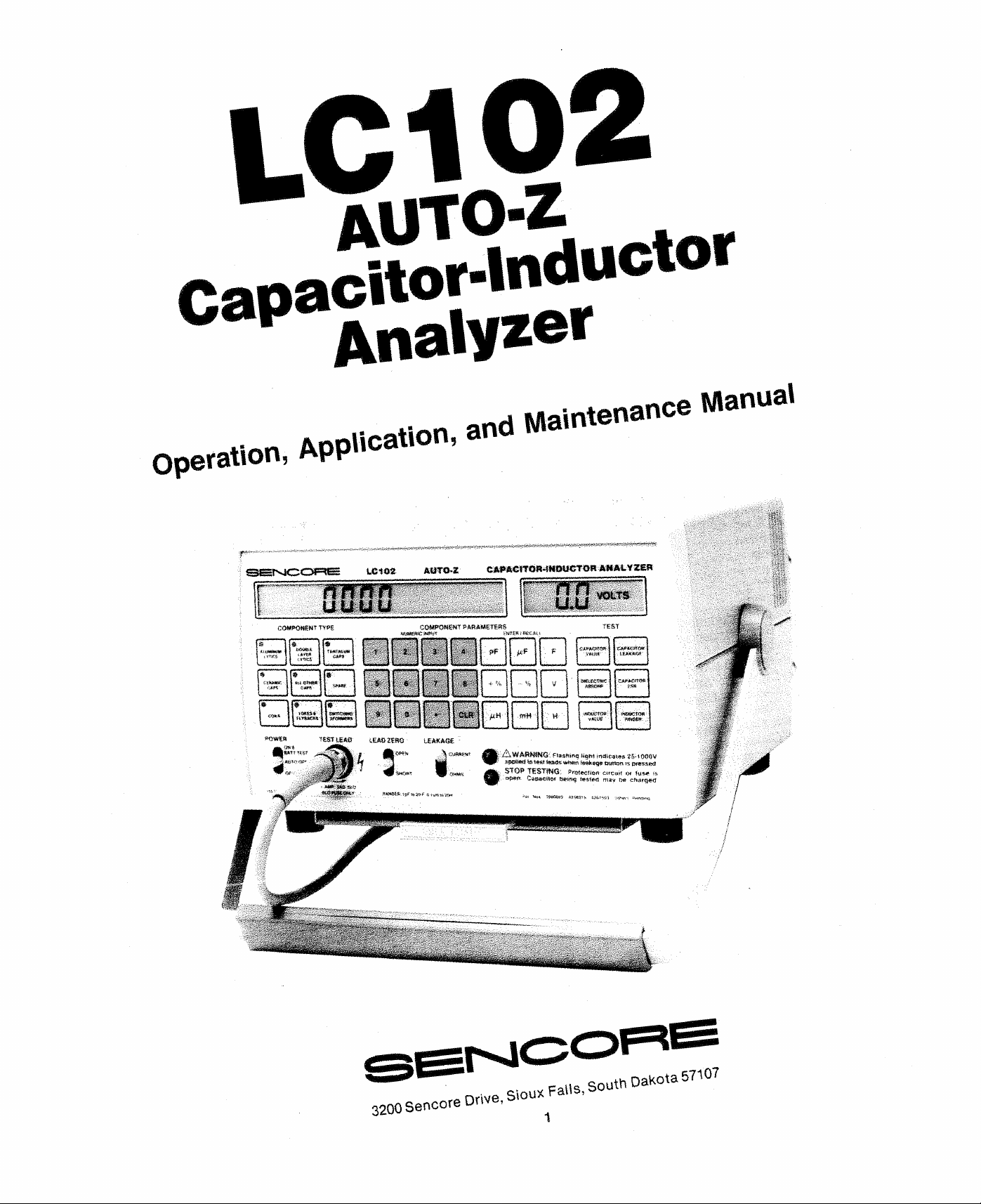
Maintenance Manua l
Operation
S Q g f s j Q O R E CC102 AUTO-Z CAPftClTOB-iNOUCTOR ANALYZER
r
« ■ .
♦
c k w i w .
¥
*OW£B
ion, Application- and
COMPONENT TYPE
i Μ > υ β ν ι
|
< .rn c s·
* Ι ί *
* U 0» H W 1 I
c m
C A W * '· \ . > i ‘ M f r · ·
* \
■ ■ « « * * · · · $
γ - ι .τ Μ β κ * j
%
--
CO M FC N W PAftAMETE^S
K
|
r w < r . M « «
S > IW « iW W i .
t f t t t M t r f t S
TEST IE AD „ΕΛΟ ZERO LEAK AGE
l·
1
j
3
6 7
5
■
■
!
# Λ''”’' t;i
h j ■ tf
's h o r t
A
■■■
PF μ:Ρ
+ %
B
cu* |
:·μϋ· ■]
/.L W A R N IN G flas hing f igm tniJiC34us 25-109QV
ST O P T E ST IN G P-retee«ofl· cir cu it 04 f us* is
•
'■. F
.... %
^ I
t r i M
· '.; W : '■
3ppi»ei teteKt leads when teakstj etnrtionts pressed
opert Caoae tto r ie ste ci may i>* ch ar ge d
•
i m c c - T f lfc ·
Λ ί β & Λ Ρ ■
1
- ie O i ^ r ttW v
j
v M i U f · ·
%
-·:· ■
VOLTS
. t E A X 'f t O . * "
C A M g t t W *
32 00 Sencore Drive, Slou*
Fails, South Dakota 57107
Page 2
TABL E OF CO NTE NTS
SAFETY PRECAUTIONS
SIMPLIFIED OPERATIONS ........................................4
DESCRIPTION
Introduction ......................................................... 6
Features.....................................................................
Specifications ..............................................................6
Controls ........................ .....................-......................8
Rear Panei Features
Supplied Accessories........................................ 10a
Optional Accessories
OPERATION
Introduction
AC Power Operation ..........................................
Battery Operation.....................................................12
Battery Test .........................................................
Recharging the Battery............................ 14
Auto O ff
STOP TESTING Indication .......................................14
Test Leads................................................... 14
Test Lead Mounting C lip
Test Lead Adapter..............................................
Test Lead Fuse...................................................15
Lead Zeroing.......................................................16
Entering Component Data .......................................16
Error C odes....................................... ................ 18
Capacitor Testing ................................
Capacitance Measurement Accuracy ......... 19
Measuring Small Capacitance Values in
Noisy Environments ...
Capacitor Parameter Testing..................................20
Measuring Capacitor Value
Measuring Capacitor Dielectric Absorption .... 20
Measuring Capacitor Leakage (Microamps) ... 21
Leakage Charts ..................................
Measuring Capacitor Leakage (ohms) .............24
Measuring Capacitor ES R..................................25
Capacitor Automatic GOOD/BAD Testing
Inductor Testing......................................................29
Balancing Out Lead Inductance
Inductor Value Testing .............................
Inductor Automatic GOOD/BAD Testing
Checking Inductors with the Ringer Test
GOOD/BAD Inductor Value Testing
............................................................
............................................................ - 14
Paper, Mica and Film Capacitor
Ceramic Capacitors
Aluminum Electrolytics ...
Tantalum Electrolytics ...
Non-polarized Electrolytics
Aluminum Electrolytics ..................................23
Tantalum Electrolytics -. ..................................
.............Inside Front Cover
........... ...................................10
................................
....................................15
...............................
........... ............ ........
........................................22
...............................
......... .................. .....
............
....................
...................22
...........................
................
.......................
.......... 30
...................31
10b
12
20
.............26
.........
........
12
13
15
19
20
22
29
30
30
6
22
22
22
24
IEEE 488 BUSS OPERATION
Connecting the LC102 for IEEE Operation.............31
Sending Data to the LC102
Component Type Commands............................33
Value Multipliers
Test Function Commands ............ ......................
General Commands ...........................................35
Reading Data from the LC102
Data Format............... ......
Separating Data Fields
Advanced Programming Ideas ..............................37
Error Testing ......................................................
GOOD/BAD Results
Shorted Capacitors .............................................38
Open Inductors ...................................................38
Making Leakage Tests with IE EE
Making ESR Tests with IEEE ............................38
Programming Examples
Sending Listener Codes ....................................39
Sending Talker Codes
Sample Programs
APPLICATIONS
Introduction ..
Indentifying Capacitor Types
Aluminum Electrolytics
Tantalum Electrolytics
Double Layer Electrolytics..................................46
Ceramic Capacitors............................................46
AH Other Capacitors ................... 47
Identifying Inductor Types .....................................47
Yokes and Flybacks
Switching Transformers
Coils ...
Identify Unknown Components..............................48
Capacitor Testing Applications ..............................49
Interpreting Capacitor Value Readings
Dielectric Stress................... ......... ... ................. .
Checking Leakage in Multi-Section Lytics .... 49
Intermittent Capacitors
Checking Ceramic Temperature
Checking Capacitance of Silicon Diodes
Testing High Voltage Diodes..............................51
Reforming Electrolytics
Inductor Testing Applications..................................52
Testing Inductors In-Circuit............. ...................52
Mutual Inductance ...............................................52
Ringing Peaking C oils
Ringing Metal Shielded Coils
Ringing Flyback Transformers ..........................53
Ringing Deflection Yokes ..................................54
Note on Solid State Yokes & Flybacks.............55
...................................................................48
Characteristics...................................................5 0
and Transistors ................................................
................................. 33
...........................................................44
.......................
...............................
....................................36
................................. ....
............................................
...................................... ....
....................................
...................................... ........
..................................44
........
.............................
........................................45
..........................................
......................................47
......................................50
......................................51
.......................................
...........................
..... .......
.....................
......... ...
....
32
34
35
36
37
37
38
39
39
40
45
47
49
49
50
52
53
2
Page 3
Cable Testing Applications
Testing Coaxial Cabie
Determining the Distance to O pe n
Locating a Short in Coaxial Cable ...............56
Determining Capacitance & Inductance
per foot .........................................................57
Using the LC102 to Find Aging Cable .........57
Hi Potential Testing.................................................57
Measuring Resistor to 1 Gigohm ...
Applications of the Leakage Power Supply
MAINTENANCE
Introduction
Recalibration and Service .......................................59
Circuit Description an d Calibration Procedures ... 59
Replacement Leads.............................................. ...59
“Spare” Button
Test Lead Fuse ........................................... ...........
Fuse Replacement
Display Te st.................... ............................. ...........
APPENDIX
Capacitor Theory and the AUTO-Z
Capacitor Types
Ceramics
Aluminum Electrolytics ......................................
Tantalum Electrolytics ..................... ...................62
A Capacitor is more than a Capacitor............. 63
Leakage
Dielectric Absorption
Effective Series Resistance
Value Change
............................................................. 59
........ ............... ..........
..................................................59
......................................................
............................................................. 61
...................................................... 63
................................... .................
....................................55
........................................
...............55
.........................58
..........
.......................59
.....................
...............
...........................
...........
....................
55
58
59
59
, 60
61
62
63
64
64
3
Page 4
SIMPLIF IED OPERAT IONS
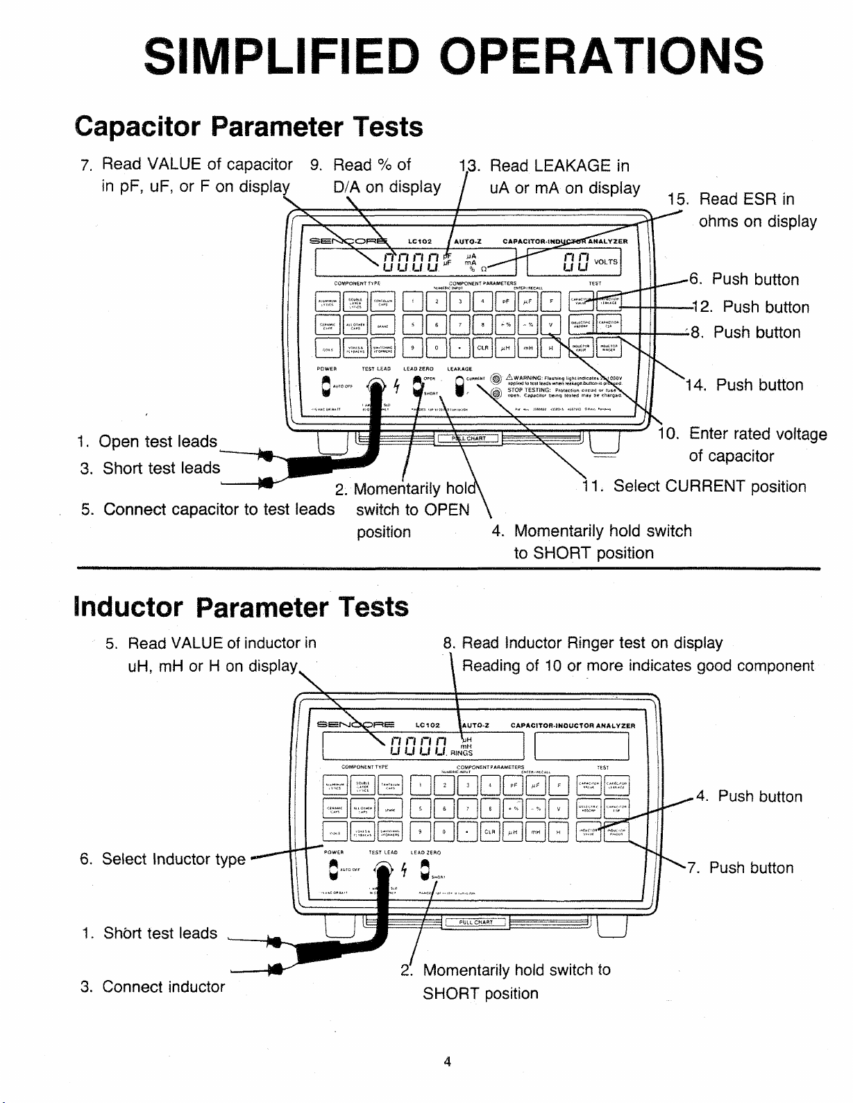
Capacitor Parameter Tests
7. Read VALUE of capacitor 9 . Rea d % of 13. Re a d LEAKAGE in
in pF, uF, or F on display D/A on display / uA or mA on display
15. Rea d ESR in
ohms on display
•6. Pus h button
-12. Pu s h button
* 8. Pus h button
14. Push button
1. Open test leads
3. Short test leads
2 . Momentarily h oi
5 . Connect capacitor to test leads switch to OPE N
positio n 4. Momentarily hold switch
Inductor Parameter Tests
5. Rea d VALUE of induc to r in
uH, m H or H on display
8. Read Inducto r Rin g er test on display
10. Enter rated voltage
of capacitor
11. Select CURRENT position
to SHORT position
Re a d i n g of 10 or mo re indicat es good co m p o n e n t
4 . Pus h button
6. Select Inductor type
1. Sh5rt test leads
3 . Connect inductor
7 . Pus h butto n
! . Momentarily h o l d switch to
SHORT pos i ti o n
4
Page 5
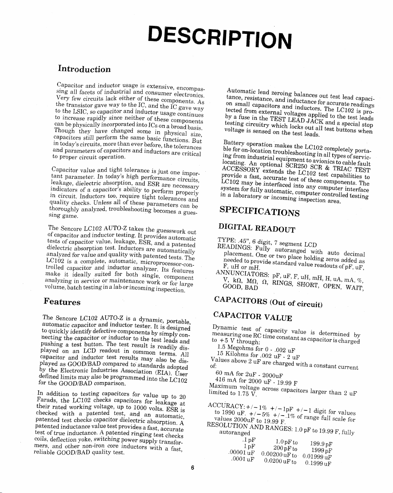
DESCRIPTION
Introduction
Γ -msritnr and indu ct or usage is extensive, encompas
sing aT L T ts of industrial and consumer electronics.
Very f L c ?rcu. ts lack either of these comp o nents. As
the tnnsistor gave way to the IC, and the IC gave way
tn t ho I STC so capacitor and inductor usage continues
o in c re a s e rapidly since neither of these components
can be physically in corporated into ICs on a broad bas i s .
ThmiiA thev have changed some m physical size ,
canac ft or s still perform the same basic functions. But
• ? A * .vniits more than ever before, the tolerances
andparameters of capacitors and inductors are critical
to proper circuit operatio n .
Automatic lead zeroing balances out test lead capaci
tance, resistance, and inductance for accurate readings
on small capacitors and ind u c tors . The LC102 is pro
tected from external voltages applied to the test leads
by a fuse in the TEST LEAD JACK and a special stop
testing circuitry which locks out all test buttons when
voltage is sensed on the test leads.
ing from industrial equipment to avionics to cable fault
uu-ιυι;ation troubleshooting in all types of servic
locating. An optional SCR250 SCR & TRIAC TEST
ACCESSORY extends the LC102 test capabilities to
provide a fast, accurate test of these co mponents. The
LC1G2 may be interfaced into any computer interface
system for fully automatic, computer controlled testing
in a laboratory or incoming inspection area.
__ r.vw.y pU l'L a-
SPECIFICATIONS
The Sencore LC102 AUTO-Z takes the guesswork out
r induct o r testing. It provides automatic
e,ts ο _ p , - Inductors are automatically
anafy ed fbrv a T u e a*d quality with patented tests. The
T Pino io o PomOlet e, automatic, mieroprocessor-con-
, n j c -+n r and inductor analyzer. Its features
" , Γ ΰ ‘suited for both single component
analyzing in service or maintenance work or for large
volume, batch testing in a lab or incoming inspection.
S k valne, leakage, ESE, and a patented
Features
Qc,„rr,yp LC102 AUTO-Z is a dynamic, portable,
automatic capacitor and inductor tester. It is designed
to auicklv identify defective components by simply con-
+· X „sm»ritor or inductor to the test leads and
pushi^ a tesf butt o n. The test result is readily dis -
β T fn readout in common terms. All
S a ectornand inductor test results may also be dis-
Dlaved as GOOD/BAD compared to standards adopted
bv the Electronic Industr i e s · Association (EIA). User
defined Hmit s may also be programmed into the LC1 02
for the GOOD/BAD co mpar ison.
In addition to
DIGITAL READOUT
TYPE: ,45”, 6 digit, 7 segment LCD
READINGS: Fully autoranged with auto decimal
placement. One or two place holding zero s added as
needed to provide standard value readouts of pF , u F ,
F, uH or mH.
ANNUNCIATORS: pF, uF, F, uH, mH, H, uA, mA, %,
V, kft, Mft, a, RINGS, SHORT, OPEN, WAIT,
GOOD, BAD
CAPACITORS (Out of circuit)
CAPACITOR VALUE
Dynamic test of capacity value is determined by
measuring one RC time constant as capacitor is charged
to +5 V through:
1,5 Megohms for 0 - .002 uF
1 5 K iloh m s for .002 uF - 2 uF
Values above 2 uF are charged with a consta n t current
of :
60 mA for 2uF - 2000u F
416 mA for 2000 uF - 19.99 F
Maximum voltage ac r o ss capacitors larger than 2 uF
limited to 1. 75 V.
Ά & Μ " upt t0 T TOlts;ESR
U 1 J a natented test, and an automatic,
checked wi , capacitor dielectric absorption. A
patented _ e vaj; Ue test provides a fast, accurate
patented inductance v g
t est of tr ue >f duc‘^witchmg power Lpply t rans fe r
ees, def lec t on yo ke ^ fes
mers, and other non
reliable GOOD/BAD quahtv test.
ACCURACY: +/— 1% +/ —lpF 47-1 digit for values
to 1990 uF. + / — 5% +/-.1% of range full scale for
values 2000uF to 19. 99 F.
RESOLUTION AND RANGES: 1.0 pF to 19 . 99 F, fully
autoranged
.1 pF 1.0 pF to 199.9 pF
lpF 20 0 pF to 1 999 pF
.000 01 uF 0.00 200 uF to 0.01999 uF
.0001 uF 0.02 00 uF to 0.1999 u F
Page 6
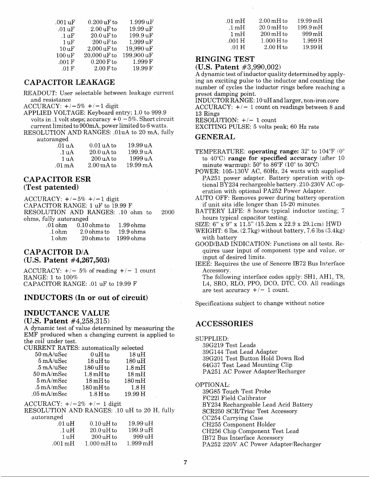
.001 uF
.01 u F
.luF
lu F
1 0 uF
100 uF
.001F 0. 200 F to
.01F
0. 200 u F to 1. 999 uF
2.00 uFto 19.99 uF
20.0 uF to 19 9.9 uF
200 uF t o 1, 999 uF
2, 000 uF t o
20 ,00 0 uF to 199,90 0 uF
2.00 F to
19,990 uF
1.999 F
19.99 F
CAPACITOR LEAKAGE
READOUT.: User selectable between leakage current
and resistance
ACCURACY: +/-5% +/-1- digit
APPLIED VOLTAGE: Keyboard entry; 1.0 to 999 . 9
volts in .1 volt s teps; acc u racy + 0 - 5 %. Short circuit
current limited to 900mA, power limited to 6 watts.
RESOLUTION AND RANGES: .OluA to 20 mA, fully
autoranged
.OluA 0.01 uA to 19.99 uA
.luA 20.0 uA to 199.9 uA
1 uA 200uAto 1999 uA
.01mA 2 . 00 mA to 19.99 mA
CAPACITOR ESR
(Test patented)
ACCURACY: +/-5% +/-1 digit
CAPACITOR RANGE: 1 uF to 1 9.99 F
RESOLUTION AND RANGES: .10 ohm to 2000
ohm s , fully autoranged
.01 ohm O.lOohmsto 1.99-ohms
.lohm 2.0 ohms to 19.9 ohm s
1 ohm 20 o hms to 1999 oh ms
CAPACITOR D/A
(U.S. Patent #4,267,503)
ACCURACY: +/- 5% of reading + / — 1 count
RANGE: 1 to 100%
CAPACITOR RANGE: . 01 uF to 19. 99 F
INDUCTORS (In or out of circuit)
0 1 mH
.1 mH
ImH
.001H
.01H
2. 00 mH to 19.99 mH
20.0 mH t o
200 mH to 99 9 mH
1.0 00 Hto
2.0 0 Hto 19.99 H
199.9 mH
1.9 99 H
RINGING TEST
(U.S. Patent #3,990,002)
A dynamic test of inductor quality determined by apply
ing an exciting pulse to the inductor and counting the
number of cycles the inductor rings before reaching a
preset damping point.
INDUCTOR RANGE: 10 uH and larger, non -i ron core
ACCURACY: -f / — 1 count on readings between 8 and
1 3 Rings
RESOLUTION: +/- 1 co unt
EXCITING PULSE: 5 volts peak; 60 Hz rate
GENERAL
TEMPERATURE: operating range: 3 2° to 104CF (0°
to 4G°C) range for specified accuracy (after 10
minute warmup): 5 0° to 86°F (10° to 30°C)
POWER: 105-13 0 V AC, 60H z , 2 4 watts with supplied
PA251 power adapter. Battery operation with op
tional BY234 rechargeable battery. 210 - 230V AC op
eration with optional PA252 Power Adapter.
AUTO OFF: Removes power during battery operation
if unit sits idle longer than 15-20 minutes.
BATTERY LIFE: 8 hours typical inductor testing; 7
hou r s typical capacitor testing.
SIZE: 6” x 9" x 11.5” (15. 2cm x 22.9 x 29.1cm) HWD
WEIGHT: 6 lb s . (2.7kg) without battery, 7.6 lbs (3.4kg)
with battery
GOOD/BAD INDICATION: Functions on all tests. Re
quires user input of compo n e nt type an d value, or
input of desired limits.
IEEE: Requires the use of Senco r e IB72 Bus Interface
Accessory.
The following interface codes app ly: SHI, AH1, T8,
L4, SRO, RLO, PPO, DCO, DTC, CO. All readings
are test accuracy +/— 1 count.
Specifications su b je ct to change without no t ice
INDUCTANCE VALUE
(U.S. Patent #4,258,315)
A dynamic test of value determined by measuring the
EMF pr od u ce d when a changing current is applied to
the coil under te s t .
CURRENT RATES: automatically selected
50 mA/uSec
5 mA/uSec
.5 mA/uSec
50 mA/mSec
5 mA/mSe c
.5 mA/mSec
0 5 mA/mSec
ACCURACY: +/-2% +/ - 1 digit
RESOLUTION AND RANGES: .10 uH to 20 H, fully
autoranged
.01 uH 0.10 u H to
.1 uH
luH
.00 1 mH 1 . 00 0 mH t o
OuH to
18 uH t o 180 uH
180 uH t o
1 .8 mH to 18 mH
1 8 mH to
180mHto
1 .8 Hto
20.0 uH t o
200 uH to
18 uH
1.8 mH
180 mH
1.8 H
19.99 H
19 . 99 uH
19 9.9 uH
999 uH
1. 999 mH
ACCESSORIES
SUPPLIED:
39G219 Test Leads
39G144 Test Lead Adapter
39 G201 Test Button Hold Down Rod
64G37 Test Lead Mounting Clip
PA251 AC Power Adapter/Recharger
OPTIONAL:
39G85 Touch Test Probe
FC221 Field Calibrator
BY234 Rechargeable Lead Acid Battery
SCR2 50 SCR/Triac Test Accessory
CC25 4 Carrying Case
CH255 Component Holder
CH256 Chip Component Test Lead
IB72 Bus Interface Accessory
PA252 220V AC Power Adapter/Recharger
7
Page 7
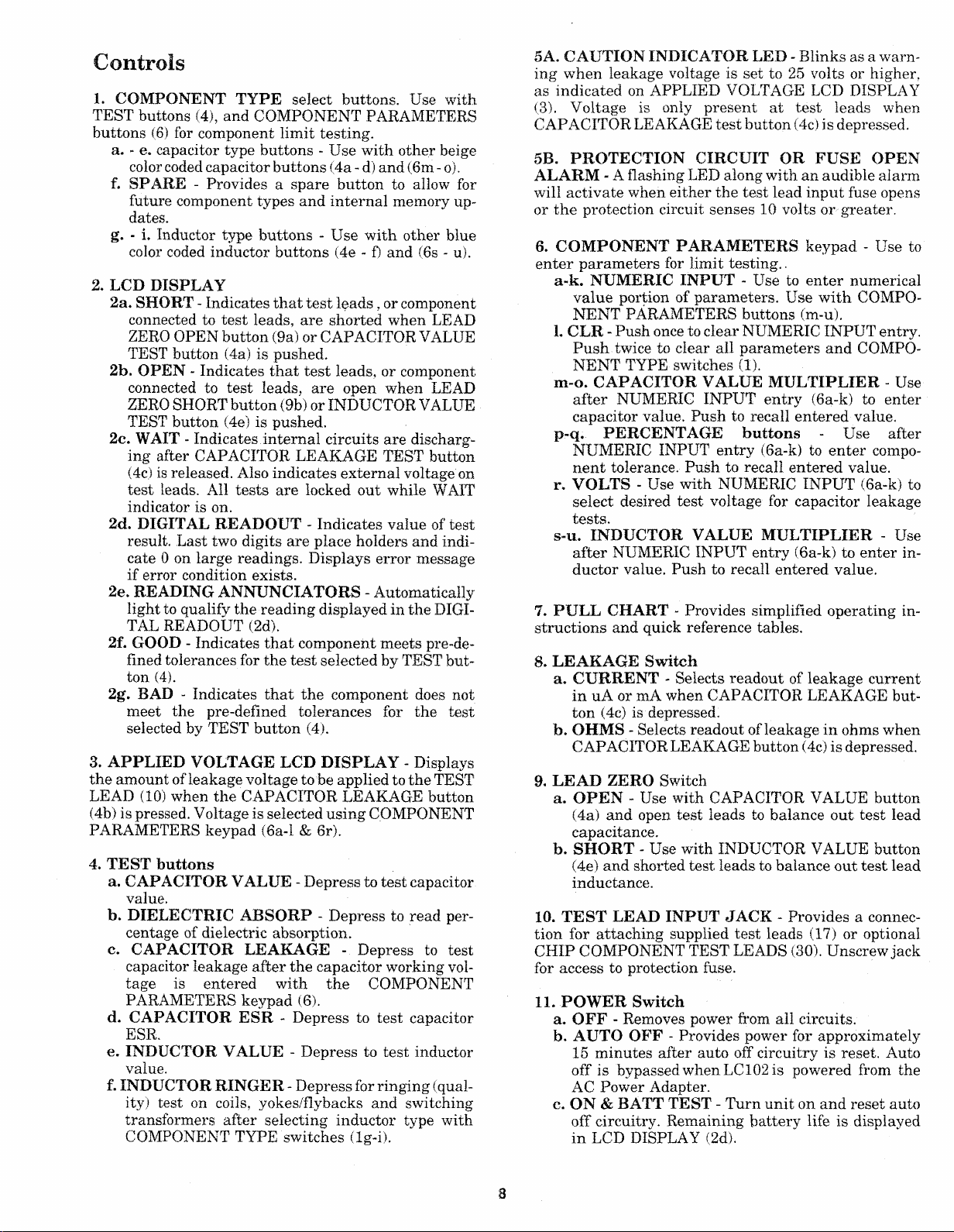
C on trols
1. COMPONENT TYPE select buttons. Use with
TEST butto ns (4), and COMPONENT PARAMETERS
butto n s (6) for component limit testing.
a. - e. capacitor type button s - Use with other beige
color cod ed capacitor button s (4a - d) and (6m - o) .
f. SPARE - Provides a spare button to allow for
future comp o n e n t types and internal memory up
dates.
g. - i. Induct or type buttons - Use with other blue
color co ded inductor buttons (4e - f) and (6s - u).
2. LCD DISPLAY
2a. SHORT - Indicates that test leads, or component
connec ted to test lea d s , are shorted when LEAD
ZERO OPEN button (9a) or CAPACITOR VALUE
TEST button (4a) is pushed.
2b. OPEN - Indicates that test leads, or compon e nt
con nected to test leads, are open when LEAD
ZERO SHORT bu tt on (9b) or INDUCTOR VALUE
TEST button (4e) is p ushed.
2c. W AIT - Indicates internal circuits are discharg
ing after CAPACITOR LEAKAGE TEST button
(4c) is released. Also indicates external voltage on
test le ads . All tests are locked out while WAIT
indicator is on.
2d. DIGITAL READOUT - Indicates value of test
result. Last two digits are place holder s an d indi
cate 0 on large readings. Displays error message
if er ro r condition exists.
2e. READING ANNUNCIATO RS - Automatically
light to qualify the reading displayed in the DIGI
TAL READOUT (2d) .
2f. GOOD - Indicates that component meets pr e-de-
flned tolerance s for the test selected by TEST but
ton (4).
2g. BAD - Indicates that the component does not
meet the pre-defmed tolerances for the test
selected by TEST button (4).
3 . APPLIE D VOLTAGE LCD DIS PLAY - Displays
the amou n t of leakage voltage to be applied to the TEST
LEAD (10) when the CAPACITOR LEAKAGE bu t t o n
(4b) is pr esse d. Voltage is selected using COMPONENT
PARAMETERS keypad (6a-l & 6r).
4. TEST buttons
a. CAPACITO R VALUE - Depress to test capacitor
value.
b. DIELECTRIC ABSORP - Depress to read per
centage of dielectric absorption.
c. CAPACITOR LEAKAGE - Depress to test
capacito r leakage after the capacitor working vol
tage is entered with the COMPONENT
PARAMETERS keypad (6).
d. CAPACITOR ESR - Depress to test capacitor
ESR.
e. INDUCTOR VALUE - Depress to test ind u c t o r
value.
f. INDUCTOR RINGER - Depress for ringing (qual
ity) test on coils, yokes/fly backs and switching
transformers after selecting inductor type with
COMPONENT TYPE switches (lg-i).
5A. CAU TIO N IND ICATOR LED - Blinks as a warn
ing when leakage voltage is set to 25 volts or higher,
as indicated on APPLIED VOLTAGE LCD DISPLAY
(3). Voltage is only present at test leads wh e n
CAPACITOR LEAKAGE test button (4c) is depressed.
5B. PROTECTION CIRCUIT OR FUSE OPEN
AL AR M - A flashing LED along with an audible ala rm
will activate when either the test lead input fuse o pens
or the protection circuit senses 10 volts or greater.
6. COM PONENT PARAMETERS keypad - Use to
enter parameters for limit testing..
a~k. NUMERIC IN PUT - Use to enter numerical
value portion of parameters. Use with COMPO
NENT PARAMETERS buttons (m-u).
1. CLR - Push once to clear NUMERIC INPUT entry.
Push twice to clear all parameters and COMPO
NENT TYPE switches (1).
m-o. CAPACITOR VALUE MULTIPLIER - Use
after NUMERIC INPUT entry (6a-k) to enter
capacitor value. Push to recall entered value.
p-q. PERCENTAGE buttons - Use after
NUMERIC INPUT entry (6a-k) to enter co mpo
nent tolerance. Push to recall entered value.
r. VOLTS - Use with NUMERIC INPUT (6a-k) to
select desired test voltage for capacitor leakage
tests.
s-u. INDUCTOR VALUE M ULTIP LIER - Use
after NUMERIC INPUT entry (6a-k) to enter in
ductor value. Pus h to recall entered value.
7. P U LL CHART - Provides simplified operating in
structions and quick reference table s .
S. LE AKAGE Switch
a. CURRENT - Selects readout of leakage current
in uA or mA when CAPACITOR LEAKAGE but
ton (4c) is depr essed.
fo. OHMS - Select s readout of leakage in ohms when
CAPACITOR LEAKAGE butt o n (4c) is d epres sed.
9. LEAD ZERO Switch
a. OPEN - Use with CAPACITOR VALUE button
(4a) and ope n test leads to balance out test lead
capacita nce.
b. SHORT - Use with INDUCTOR VALUE button
(4e) and shorted test leads to balance out test lead
induct a n ce .
10. TEST LEAD INPUT JACK - Provides a connec
tion for attaching supplied test leads (17) or optiona l
CHIP COMPONENT TEST LEADS (30). Unscrew jack
for acce s s to protection fuse .
11. POW ER Switch
a. OFF - Removes power from all circuits.
b. AUTO OFF - Provides power for approximately
1 5 minutes after auto off circuitry is reset. Auto
off is bypassed when LC 1 0 2 is powered from the
AC Power Adapter.
c. ON & BATT TEST - Turn unit on and reset auto
off circuitry. Remaining battery life is displayed
in LCD DISPLAY (2d).
8
Page 8
CO MPONENT TYPE
CO MPONENT PA RAM ETER S
NUM Efi iC INP UT gNT SR ! RE CA L L
TEST
p SINGE
POWER
O N S A
BA TT TE ST
AUT O O f f· B
OFF C
! 1S V AC Q fl B A ?1
2c\
2b— OPEN
2a -
TEST LEAD
LEAD ZE R O LE A KAGE
/^ W A R N IN G : Flashing tight i ndicates 25-1000V
applie d to tes t lead s wh en leakage bu tt o n is pressed.
TOP TE S T I N G : P r o t ectio n c i rcuit or fuse is
Capacit o r be ing tested may be cha rg ed.
Nos.· 3S9« 00 2. . ' « s e a ts . « 6 7 M 3 . Ori w n Pffndiny
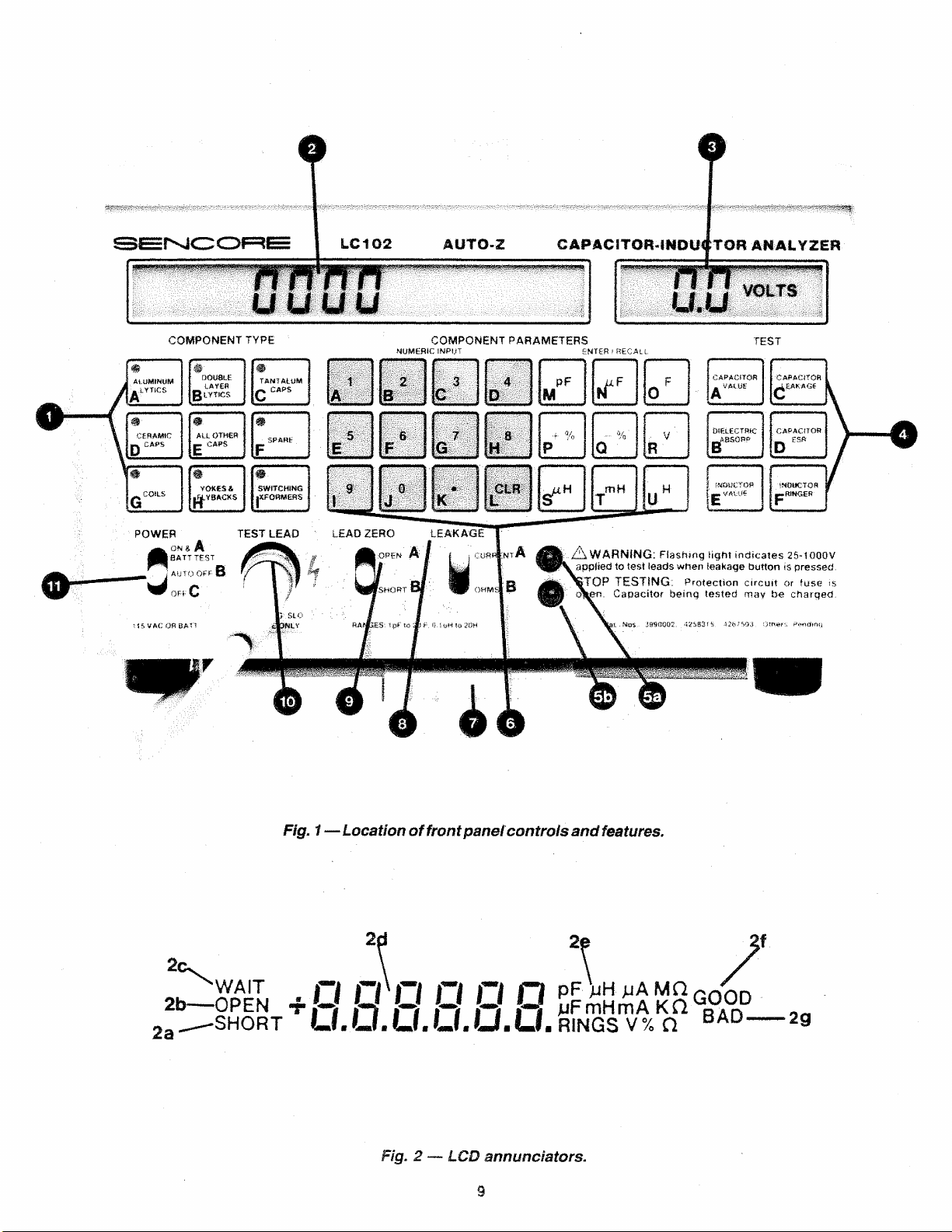
Fig. 1— Locat ion of fr ont panel· controls and features.
2d 2e 2f
'WAIT
•OPEN 4 ' O Q O Ο Ο O SprnHmA K ftG O O D -
SHORT LI . O. LI . LI . U. U. RINGS V% Ω BA D
------
29
Fig. 2 — LCD annunciators.
3
Page 9
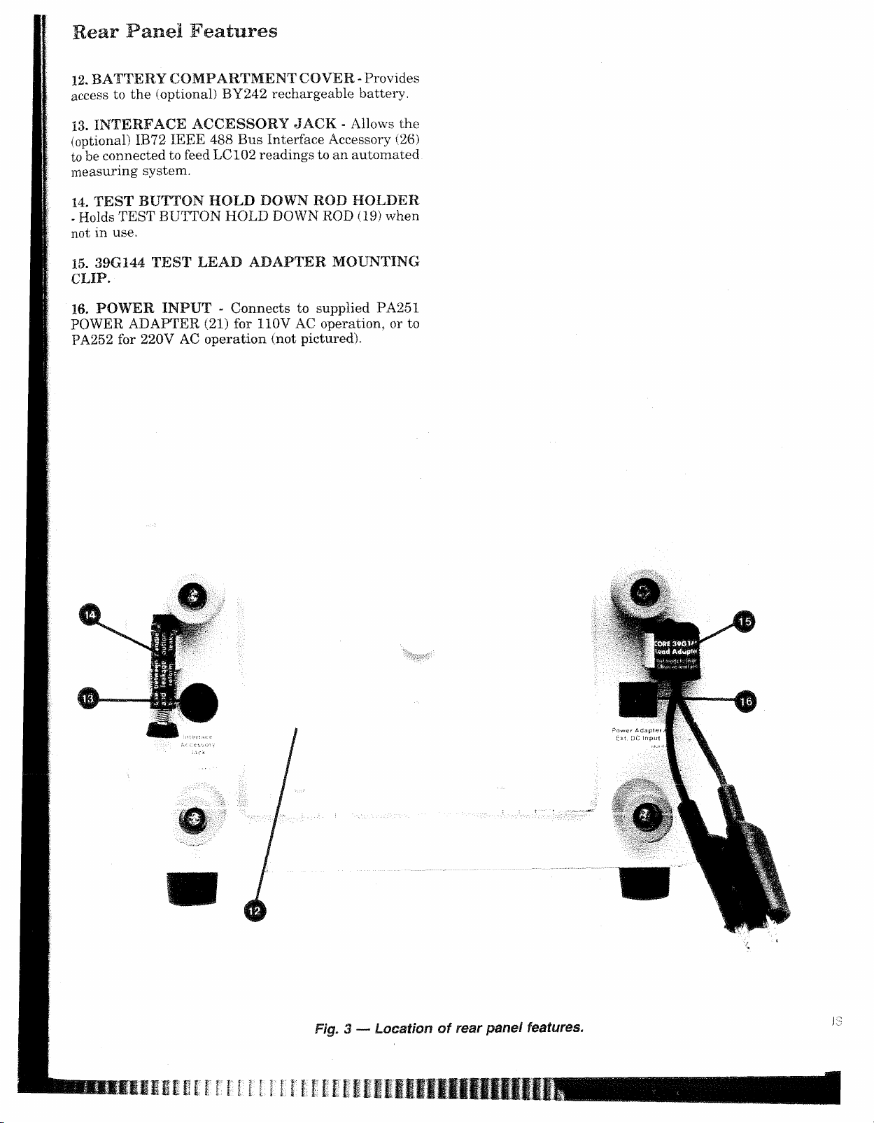
Rear Fane! Features
12. BATTERY COM PARTM ENT COVER - Provides
acces s to the (optional) BY242 rechargeable battery.
13. INTERFACE ACCESSORY JACK - Allows the
(optional) IB72 IEEE 488 Bus Interface Accessory (26)
to b e connec t ed to feed LC102 readings t o an automated
measuring system.
14. TEST BUTTON HOLD DOWN ROD HOLDER
- Ho lds TEST BUTTON HOLD DOWN ROD (19) when
not in use.
15. 39G144 TEST LEAD ADAPTER MOUNTING
CLIP.
16. POWER INPU T - Connects to supplied PA251
POWER ADAPTER (21) for 110V AC operation, or to
PA252 for 220V AC operation (not pictured).
Fig. 3 — Location of rear panel features.
Page 10
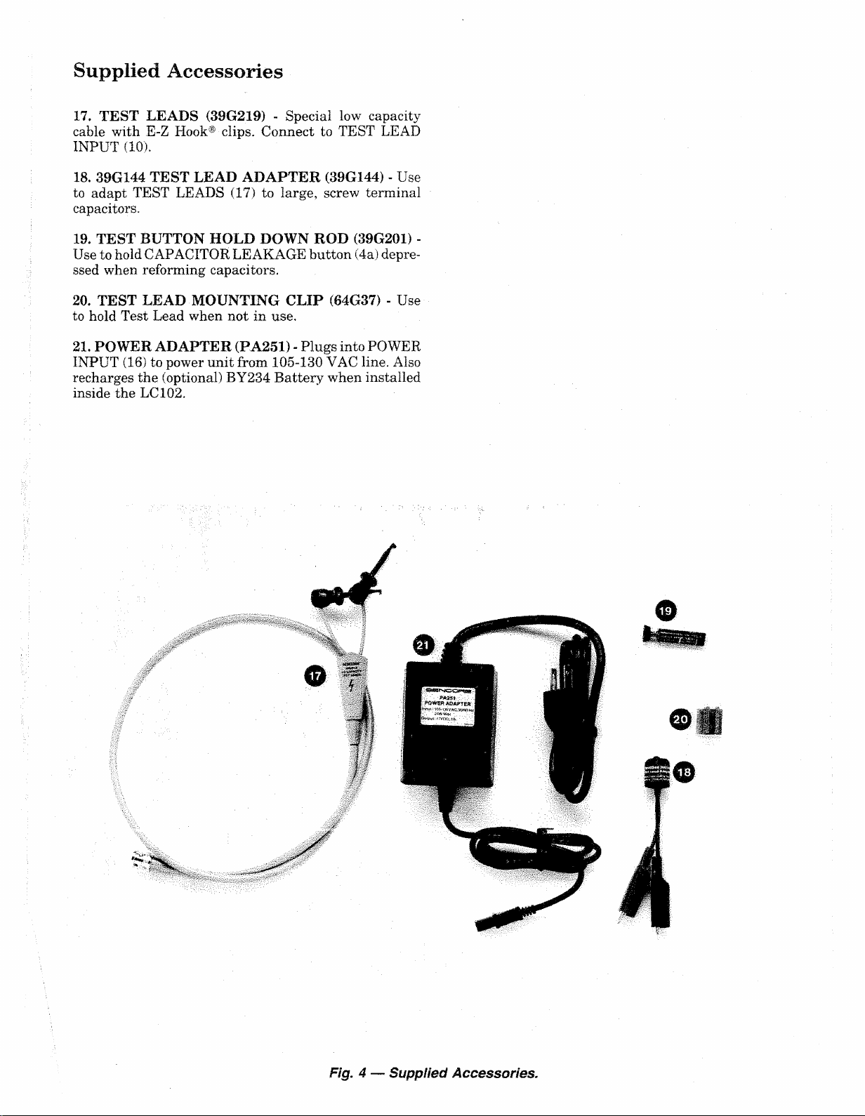
Supplied Accessories
17. TEST LEADS (39G219) - Special low capacity
cable with E-Z Hook® clips. Connect to TEST LEAD
INPUT (10) .
18. 39G144 TEST LEAD ADA PTER (39G144) - Use
to ada pt TEST LEADS (17) to large, screw terminal
capacitors.
19. TEST BUTTON HOLD DOWN ROD (3 9G201) -
Use to ho ld CAPACITOR LEAKAGE b utton (4a) depre
ssed when reforming capacitors.
20. TEST LEAD MOUNTING CLIP (64G37) - Use
to hold Test Lead when not in use.
21. POWER ADAPTER (PA251) - Plugs into POWER
INPUT (16) to power unit from 105-130 VAC line . Also
recha rges the (optional) BY234 Battery when installed
inside the LC102.
Fig. 4 — Supplied Accessories.
Page 11
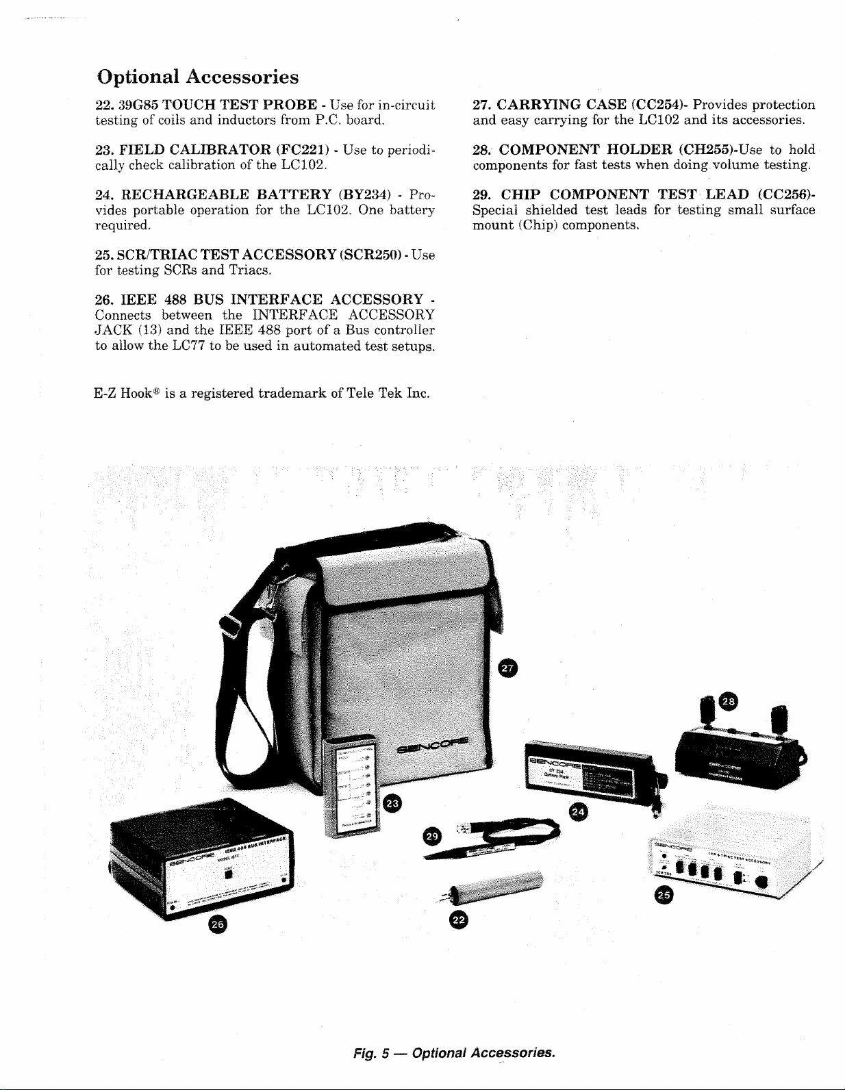
Optional Accessories
22. 39 G85 TOUCH TEST PROBE - Use for in-circ uit 27. CARRYING CASE (CC254)- Provides protection
testing of coils and inductors from P.C. board. and easy carrying for the LC102 and its accessorie s.
23. FIELD CALIBRATOR (FC2 2 1 ) - Use to periodi
cally check calibration of the LC1 0 2 .
24. RECHARGEABLE B ATTERY (BY234) - Pro
vides portable operati on for the LC10 2. One battery
required.
25. SCR/TRI AC TEST ACCESSORY (SCR250) - Use
for testing SCRs and Triacs.
26. IEEE 488 BUS INTERFACE ACCESSORY -
Connects between the INTERFACE ACCESSORY
JACK (13) and the IEEE 488 port of a Bus controller
to allow the LC77 to be used in automated test setups.
E-Z Hook® i s a registered trademark of Tele Tek Inc.
28. COMPONENT HOLDER (CH255)-Use to hold
components for fast tests when doing, volume testing.
29. CHIP COMPONENT TEST LEAD (CC256)-
Special shielded test leads for testing small surface
mount (Chip) components.
Fig. 5 — Optional Accessories.
Page 12
O PE RA TION
Introduction
Before you begin to u se your LC102 AUTO-Z, take a
few minutes to read through the Operations and Appli
cations sections of this manual and acquaint yourself
with the features and capabilities of your instrument.
After you have familiarized yourself with the general
operation of the LC 102, most tests can be performed
with the information on the front panel.
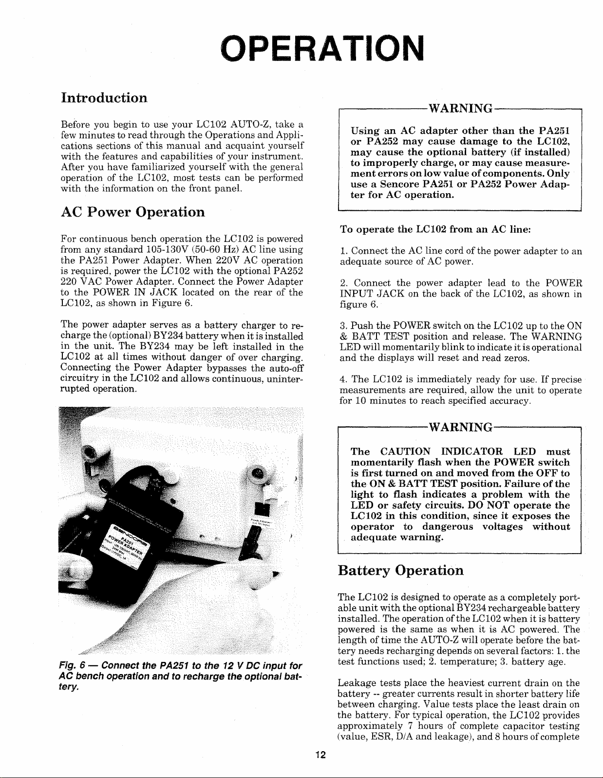
AC Power Operation
For continuous bench operation the LC1 0 2 is powered
from any st andard 1 05-130V (50-60 Hz) AC line usi ng
the PA251 Power Adapter. When 220V AC operation
is required, power the LC102 with the optional PA252
220 VAC Power Adapter. Connect the Power Adapter
to the POWER IN JACK located on the rear of the
LC102 , as shown in Figure 6 .
--------------------
WARNING
--------------------
Using an AC adapter other than the PA251
or PA252 may cause damage to the LC102,
may cause the optional battery (if installed)
to improperly charge, or may cause measure
ment errors on low value of components. Only
use a Sencore PA251 or PA252 Power Adap
ter for AC operation.
To operate the LC102 from an AC line:
1 . Connect the AC line cord of the power adapter to an
adequate s ource of AC power.
2. Connect the power adapter lead to the POWER
INPUT JACK on the back of the LC102, as shown in
figure 6 .
The power adap ter serves as a battery charger to re
charge the (optional) BY234 battery when it is installed
in the unit. The BY234 may be left installed in the
LC102 at all times without danger of over charging.
Connecting the Power Adapter bypass es the auto-off
circuitry in the LC1 0 2 and allows continuous, uninter
rupted oper ation .
Fig. 6 — Connect the PA251 to the 12 V DC input for
AC bench operation and to recharge the optional bat
tery.
3. Push the POWER switch on the LC102 up t o the ON
& BATT TEST positio n and release . The WARNING
LED will momentarily blink to in dicate it is operational
and the displays will reset and rea d zeros.
4. The LC102 is immediately ready for use. If prec ise
measurements are required, allow the unit to operate
for 1 0 minutes to reach specified accu racy.
-----------------------WARNING
----------------------
The CAUTION INDICATOR LED must
momentarily flash when the POWER switch
is first turned on and moved from the OFF to
the ON & BATT TEST position. Failure of the
light to flash indicates a problem with the
LED or safety circuits. DO NOT operate the
LC102 in this condition, since it exposes the
operator to dangerous voltages without
adequate warning.
Battery Opera tion
The LC102 is designed to operate as a completely port
able unit with the optional BY234 rechargeable battery
installed. The operat ion of the LC1 0 2 when it is battery
powered is the same as when it is AC powered. The
length of time the AUTO-Z will operate before the bat
tery needs recharging dep ends on several factors: 1 . the
test functions used; 2. tem perature; 3. battery age.
Leakage tests place the heaviest current drain on the
battery — greater current s result in shorter battery life
between charging. Value tests plac e the least drain on
the battery. For typical operation, the LC102 provides
approximately 7 hou rs of complete capacitor testing
(value, ESR, D/A and leakage), and 8 hours of complete
12
Page 13
ind uctor testing (value and ringing). These times, of
course, will vary with temperature and battery age.
As the temperature of the battery decreases, its cap ac
ity also decreases. The operating time between recharg
ings decreases at the rate of approximately 1 hour for
every 20 degrees F drop in temperature below 70°F.
The BY234 battery is a sea led, lead-acid type which
requires no maintenance other than recharging. As a
battery ages, it will require more frequent rech argings.
If used properly, the BY234 will provide several years
of service before needing replacement.
You can maximize the lifetime of the BY234 several
ways: 1. Never allow the battery to deeply discharge.
The LC102 has a built-in battery test and low battery
shut off circuitry. Check the remaining charge per iod
ically and recharge the battery before the low battery
circu it shut s the unit off. 2 . Keep the battery fully
charged. The BY234 will not be harmed if it is left
installed in the LC1 02 during AC operation. Instead,
this will keep the battery fresh an d ready for use and
will actually lengthen its useful lifetime. 3. Rec harge
the battery before using it if it has sat idle for more
than a couple of weeks. Lead-acid batteries normally
loose some of their charge if they sit idle for a per iod
of time.
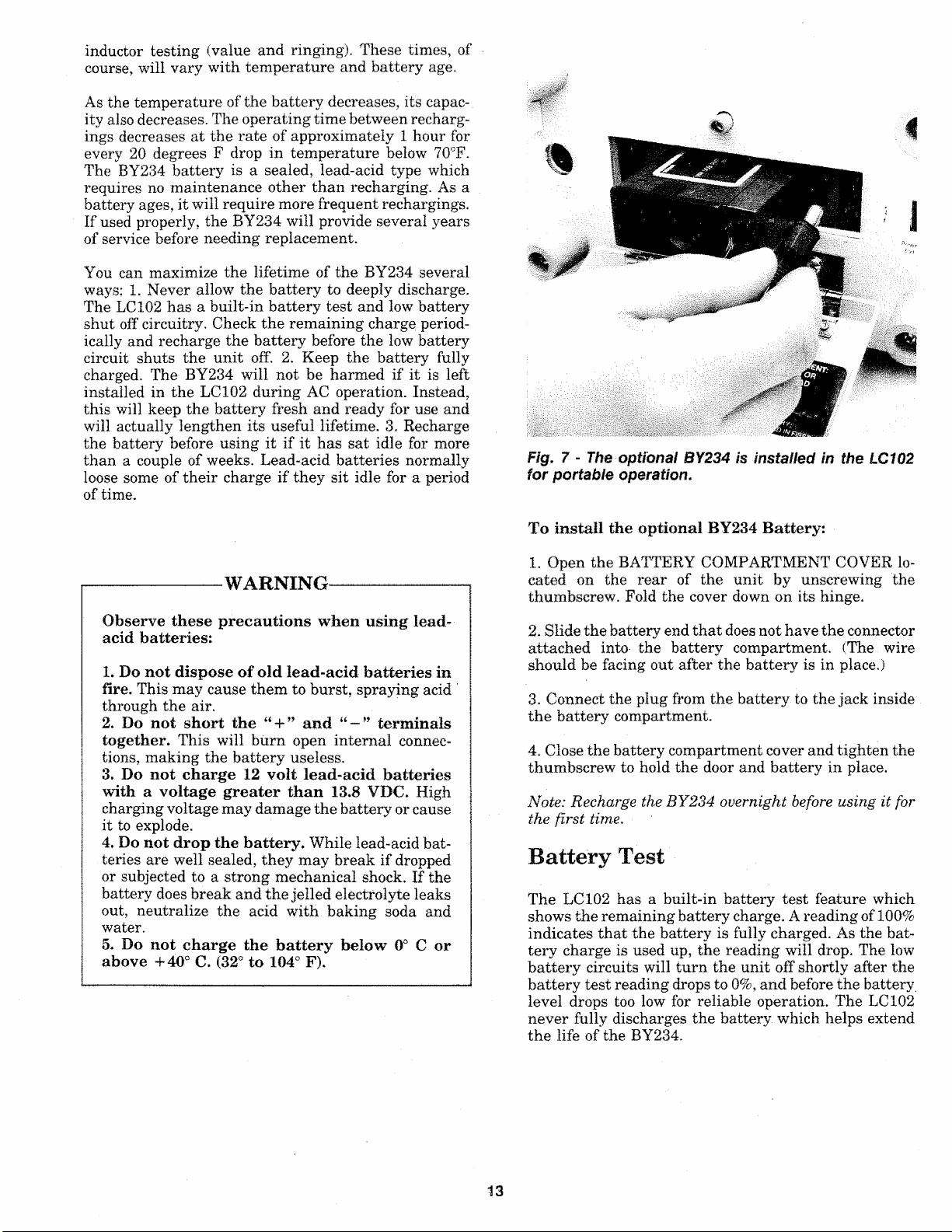
Fig. 7 - The optional BY234 is installed in the LC102
for portable operation.
-------------------
WARNING---------------------
Observe these precautions when using lead-
acid batteries:
1. Do not dispose of old lead-acid batteries in
fire. This may cause them to burs t, spraying acid
through the a ir.
2. Do not short the “ + ” and terminals
together. This will bum open internal connec
tio ns, making the battery useless.
3. Do not charge 12 volt lead-acid batteries
with a voltage greater than 13.8 VDC. High
charging voltage may damage the battery or cause
it to explode.
4. Do not drop the battery. While lead-aci d bat
teries are well sealed, they may break if drop ped
or subjected to a strong mechanical shock. If the
battery does break and the jelled electrolyte leak s
out, neutralize the acid with baking soda and
water.
5. Do not charge the battery below 0° C or
above +40° C. (32° to 104° F).
To install the optional BY234 Battery:
1 . Open the BATTERY COMPARTMENT COVER lo
cated on the rear of the unit by unscrewing the
thumbscrew. Fold the cover down on its hing e.
2. Slide the battery end that does not have the connector
attached into- the battery compartmen t. (The wire
should be facing out after the battery is in place.)
3. Connect the plug from the battery to the jack inside
the battery compartment.
4. Close t he battery co mpartmen t cover and tighten the
thumbscrew to hold the door and battery in place.
Note: Recharge the B Y 2 3 4 overnight b ef ore using it for
the f i rst time.
Battery Test
The LCX0 2 has a built-in battery test feature which
shows the remaining battery charge. A reading of 100%
indicates that the battery is fully charged. As the bat
tery charge is used up, the reading will drop. The low
battery circuits will turn the unit off shortly after the
battery test reading drops to 0 %, and before the batt ery,
level drops too low for reliable operation. The LC102
never fully discharges the battery which helps extend
the life of t he BY234.
13
Page 14
To perform the battery test:
Au to Off
1. With a BY234 installed, move th e POWER switch
to the ON & BATT TEST position.
2. Read the percentage of remaining battery charge in
the LCD DISPLAY.
3. If th e reading shows 0%, the unit may not operate,
or operate for just a short time since the low battery
circuit turns the LC102 off at this battery level.
C O M P O N E N T T y p e
i . v T i C S
CAP
c
s
J
^ &
- X N iS i.f - ·
m
A | , L O T K F #
C A P ?
■ ' O K F S 1
f i Y B a C K s -
H
W I
Έ Γ
*
ronMEftC
)!,
I
" η
i l U M i f i l J M
m
C O t^ s
— 1 1
P O W E R r g
To co nserve battery charg e, the LC102 contains an auto
off circuit . This circuit keeps the batterie s from running
down if you sh ould forget to turn the unit off, but keeps
the AUTO-Z powered up during use. The auto off circuit
will shut the LC102 off after approximately 15 minutes
if none of the front panel buttons have been pushed.
Pushing any COMPONENT TYPE button, COMPO
NENT PARAMETERS butt on, TEST bu tton, or
momentarily moving the POWER button to the ON &
BATT TEST position will reset the auto off circuits.
The auto off circuits are bypassed when the LC1 0 2 is
operate d from the AC Power Adapter.
To operate the LC102 using the optional BY234
battery:
1. Install the BY234 battery into the LC1 02 battery
compartment.
NOTE: If you are using the BY234 for the first time,
be sure to charge the battery before using the LC1 0 2 .
Though factory te sted, the BY234 may not be charged
when you receive it.
2. Push the POWER switch to the ON & BATT TEST
position and release. The WARNING LED will momen
tarily blink to indicate it is operational and the display s
will reset and read zeros.
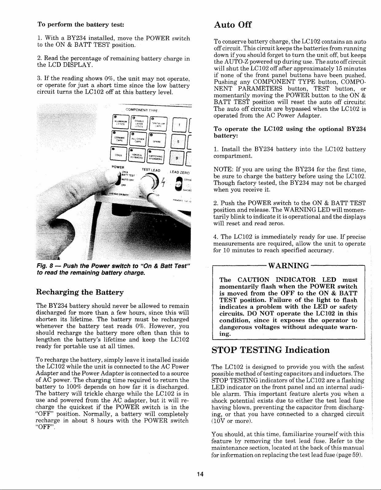
Fig. 8 — Push the Pow er sw itch to “On & Batt Te st
to read the remaining battery charge.
Recharging the Battery
The BY234 battery should never be allowed to remain
discharged for more than a few hours, since this will
shorten its lifetime. The battery mus t be recharged
whenever the battery test reads 0%. However, you
should recharge the battery more often than this to
lengthen the battery’s lifetime an d keep the LC1 0 2
ready for portable use at all times.
To recharge the battery, simply leave it installed inside
the LC102 while the unit is connected to the AC Power
Adapter and the Power Adapter is conn ected to a source
of AC power. The charging time required to return the
battery to 10 0% depends on how far it is dischar ged.
The battery will trickle charge while the LC1 02 is in
use and powered from the AC adap ter, but it will re
charge the quickest if the POWER switch is in the
“OFF” position. Normally, a battery will completely
recharge in about 8 hours with the POWER switch
“OFF”.
4. The LC102 is immediately ready for use. If precise
measur ements are required, allow the unit to operate
for 1 0 minutes to reach specified accuracy.
------------------- WARNING
-------------------
The CAUTION INDICATOR LED must
momentarily flash when the POWER switch
is moved from the OFF to the ON & BATT
TEST position. Failure of the light to flash
indicates a problem with the LED or safety
circuits. DO NOT operate the LC102 in this
condition, since it exposes the operator to
dangerous voltages without adequate warn
ing.
STOP TEST ING Indication
The LC102 is de signed to provide you with the safest
possible method of testing capac itors and inductors. The
STOP TESTING indicators of the LC102 are a flashing
LED indicator on the front panel and an internal audi
ble alarm. This important feature alerts you when a
shock potential exists due to either the test lead fuse
having blown, preventing the capaci tor from discharg
ing, or that you have connect ed to a charged circuit
(1 0 V or mo re).
You should, at this time, familiarize yourself with this
feature by removing the test lead fuse. Refer to the
maintenance section, located at the back of this manua l
for information on replacing the test lead fuse (page 59).
14
Page 15

If the STOP TESTING indicators activate:
1. Stop all testing with the LC 102.
N O T E : D o not mou n t the T E S T L E A D M O U N T I N G
CL I P t o th e sides of the A U T O - Z . as this w i l l in ter f e re
with the handle movement.
2 . Carefully discharge the capacitor you are testing by
connecting a 1 0 k ohm 1 watt resistor across the termi
nals.
3. Replace the test lead fuse if blown, or remove the
voltage from the point the test lea ds are connected to.
4. Resume testing.
Test Leads
The test leads supplied with the LC102 (39G219) are
made of special, low capacity coaxial cable. Using any
other cable will add extra capaci ty to the meter circuits,
which may not be within the range of the lead zeroing
circuits. Attempting to zero the leads with another,
higher capacitance cable conn ected will cause the LCD
DISPLAY to show the messag e error. This indicates
that the value is beyond the zeroing limits of the LC1 0 2 .
If the test leads ever require replaceme nt, new leads
(part #39G219) may be ord ered directly from the: SEN
CORE SERVICE DEPARTMENT at 3 200 Sencore
Drive, Sioux Falls, SD 57107.
Test Lead Mounting Clip
Test Lead Adapter
Some larger value electrolytic capacitors have screw
terminals rather than the conventional wire leads or
sold er terminals. To connect the LC102 to these
cap acitors you will need to use the suppl ied 39G144
TEST LEAD ADAPTER. The TEST LEAD ADAPTER
conv erts the E-Z Hook ® clips of the test leads to al
ligator clips which will clamp onto the large screw ter
minals. A mounting clip on the back of the LC 102 stores
the TEST LEAD ADAPTER when it is not in use.
A TEST LEAD MOUNTING CLIP (64G37) is supplied
with the LC102. This clip is useful to hold the test leads
out of the way when not in us e, but keeps them ready
and within reach at any time. The mounting clip may
be attached on the top of the LC102, on the side of the
handl e, or wherever it is most convenie nt. To mount
the clip, peel off the backing, place the clip in the desired
location and press it firmly in place.
Fig. 10 - The 39G144 Test Lead Adapter allows large,
screw-terminal capacitors to be connected to the
LC102.
To use the TEST LEAD ADAPTER:
1. Connect the red E-Z Hook® of the LC102 test lead
to the red TEST LEAD ADAPTER terminal.
2. Connect the black E-Z Hook® to the black adapter
terminal.
3. Connect the red TEST LEAD ADAPTER lead to th e
“ 4-” capacitor terminal, and the black lead to the “ — ”
terminal.
4. Test the capacitor in the usual manner.
Fig. 9 — The test lead mounting clip holds the test
leads out o f the way, yet ready for use at anytime.
Test Lead Fuse
A 1 amp, Slo Bio (3AG) fuse is located in th e TEST
LEAD input jack on the front of the AUTO-Z. This fuse
protects the unit from accidental external voltage or
current over loads.
15
Page 16
Lead Zeroing
The test leads c onn ected to the LC1 02 have a certain
amount of capacitance, resista nce, an d inductance
which must be balanced out before measuring small
value capacitors and ind uctors or before measuring
capacitor ESR. The test lead impedence should be
zeroed when the LC102 i s first turned on. It will re main
zeroed as long a s the unit is powered on. If the LC102
is battery operated and is turned off by the Auto Off
circuits, however, the lead s mu st be rezeroed.
To zero the test leads:
1. Turn the LC102 o n by momentarily pushing the
POWER switch to the ON & BATT TEST position.
2. Connect the test le ads to the TEST LEAD INPUT
jack on the front of the AUTO-Z.
3. Place the open test le ads (with nothing connected)
on the work area with the red and black test clip s next
to each other, but not touchin g.
4. Move the LEAD ZERO switch to the “OPEN” posi
tion. Release whe n a “ — ” begins to move through the
display.
5. Connect the red and black test clips together.
6 . Move the LEAD ZERO switch to the “SHORT” pos
ition, a nd release when a “ —” begins to move through
the display.
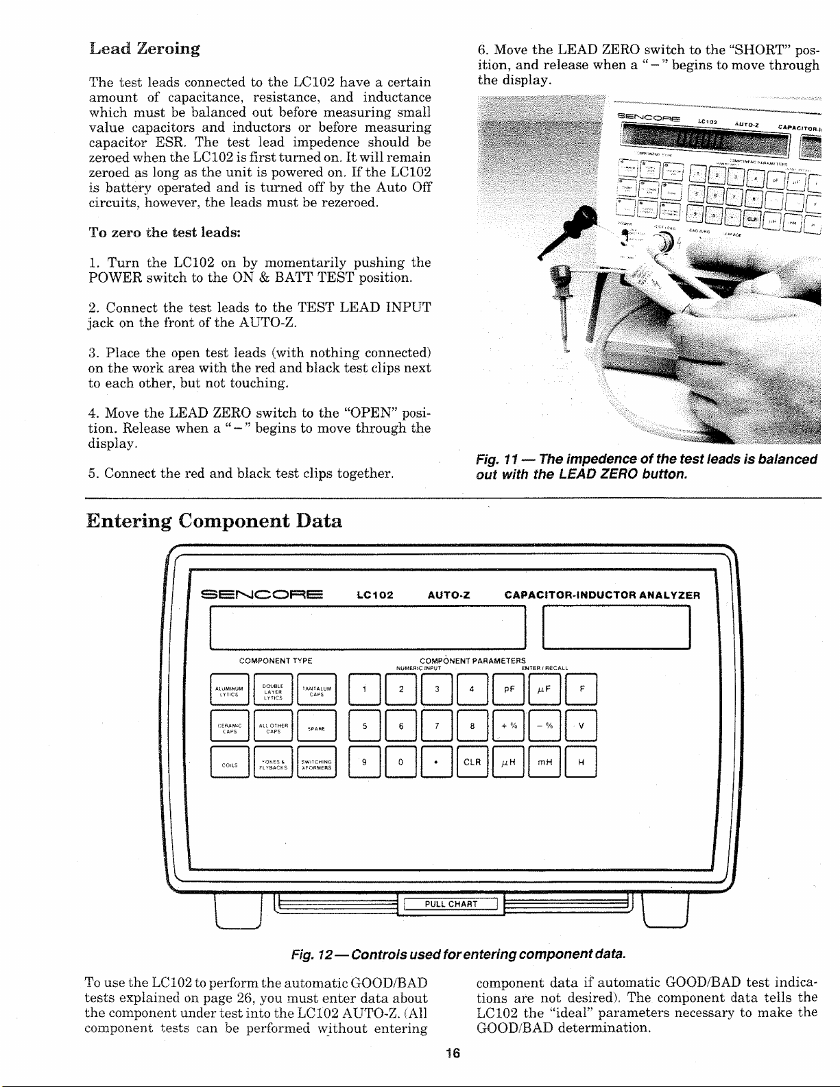
Fig. 11 — The impedence o f the test leads is balanced
out with the LEAD ZERO button.
Entering Component Da ta
Fig. 12— Controls used for entering component data.
To use the LC102 to perform th e automatic GOOD/BAD
tests explained on page 26, you must enter data about
the component under test into th e LC102 AUTO-Z. (All
component tes ts can be performed without entering
component data if au tomatic GOOD /BAD test indica
tions are not desired). The component data tells the
LC102 the “ideal” parameters necessary to make the
GOOD/BAD determination.
16
Page 17
The component data which can be entered into the
LC102 includes : component type, value, tolerance and
rated working voltage for capa citors, and component
type, value, and tolerance for inductors and coils. These
parameters are usually marked on the component, or
can be determined by looking the component up in a
parts list or replacement guide. The APPLICATIONS
sect ion of this manual contains information on how to
identify capacitor an d inducto r types.
N O T E : All component data can be cleared by p ushing
the “C L R ” button on the gra y C O M P O N E N T
P A R A M E T E R S keypad twice.
To Enter Component Type:
N O T E : The C O M P O N E N T T Y P E switches t ell the
L C 1 0 2 what kind of component is being te s ted.
1 . Press the desired COMPONENT TYPE button. Use
the beige color coded buttons when checking capacitors
and the blue buttons when checking inductors.
2. A red LED indicator in the comer of the COMPO
NENT TYPE button lights w hen that button is selected.
To Enter Component Value:
1. Enter a numb er, up to 3 significant digits, equal to
the value of the cap acitor or inductor. (Example: “123”.
or “123000.”). Each digit will appear in the display as
a key is pus hed.
a . T h e LC1 0 2 rounds the entry do w n if y ou enter a
nu m be r having more than 3 significant digits ( E x a m
ple: “1239” becomes “123 0”).
b. T h e LC 1 0 2 accepts nu m b e rs up to 6 places befo re
the decimal. (Example: “1000 0 0 ”). Entries larger
than th i s re s e t to 0.
c. The LC1 02 accepts numbers up to 5 places a f t e r
the decimal for numbe r s les s than 1. (Example:
“0.00001” ) . Entries smaller than t hi s resul t in “Error
2”.
d. All unnecessary place holder dig it s are dropped.
(Example: “.06700” becomes “.067”).
e. Pu s h the “C L R ” button once t o clear the value entry
an d s t a rt ov e r .
To Enter Compone nt Tolerance :
1 . Enter a 1, or 2 or 3 digit number up to 100 which
equa ls to the “ + ” value tolerance of the capacitor or
inductor. Do not use a decima l.
2. Press the white “ + %” COMPONENT PARAMET
ERS button.
3. Enter a 1 or 2 digit number up t o 99 which equals
to the “ - ” value tolerance of the ca pacitor or inductor.
Do not use a decima l.
4. Press the white
ERS bu tton.
5. To check the entered percentage, press the white
“ + %” or “ — %” button at any time.
SEN1CORE LC102 AUTO-Z CAPACiTCm-IMQUCTOR ANALYZER
0 u 0 u ‘
■%” COMPONENT PARAMET-
COMPQNFf*? PARA(*Ft£i
□ □ □ □ 0
0000
0000
SENCORE
LC 1Q2 A UTO*Z
π η η n
u.u.u.u.
CAPACITOR.IXOUCTOft ANALYZER
. COMPONENT PABAWfTfiflS
2. Enter the desired capacitor value multiplier or induc
tor value multiplier.
a . Th e capacitor value range i s 1 p F to 19.9 F . The
inductor value range i s .1 u H to 19.9 H. Entering
values beyond th i s range causes an “Error 2 ”.
b . T h e L C 1 0 2 accepts non-conventional value nota
ti o ns, such as “.00001 F ”, “.00002 u F ” or “100 0 0 0 p F ”
3. After entering the multiplier, the display momentar
ily shows the entered value and multiplier before re
turning to a “0000” read ing. The LC102 is now ready
for the next parameter entry.
4. To check the entered capacitor value at any time,
pu sh any beige colored capacitor value multiplier but
ton. To check the ente red induct or value push any blue
colored ind uctor value multiplier button.
5. To change φΐ entered value parameter, repeat step s
1 & 2 .
□00 000 0
00000
SE NC C3RE LC 102 AUTO-Z CAPACITOR· INDUCT OH ANALYZER
u u
0000
0000
0000
d
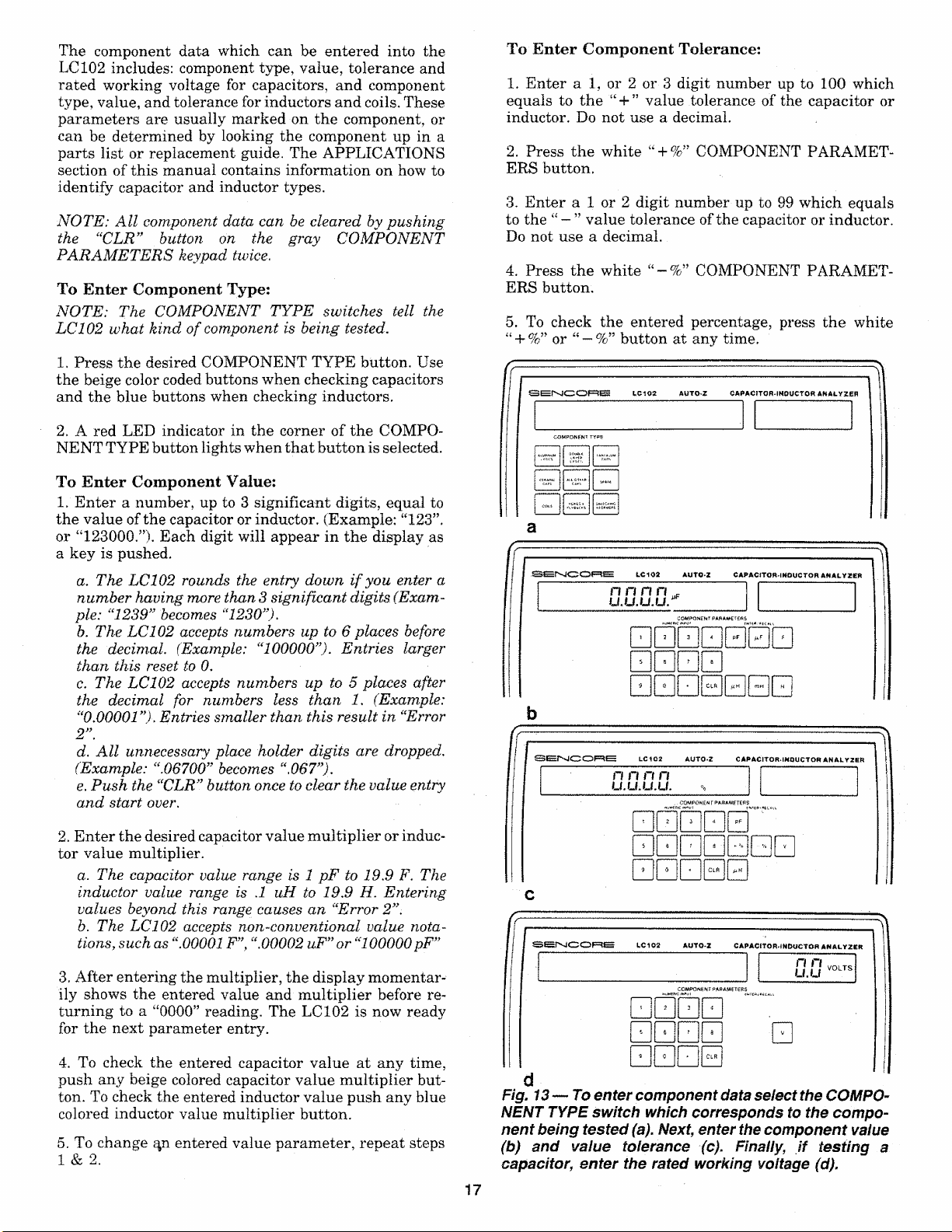
Fig. 13 — To enter component data select the COMPO
NENT TYPE switch which corresponds to the com po
nent being tested (a). Next, enter the com ponent value
(b) and value tolerance (c). Finally, if testing a
capacitor, enter the rated working voltage (d).
17
Page 18
To Enter Leaka ge Volta ge:
1 . Enter the desired voltage from 1 to 999.9 using the
gray keys on the NUMERIC INPUT keypad. A decimal,
followed by one digit may be entered, but is not neces
sary.
2. Push the white “V ” key to enter the voltage. The
voltage will appear in the applied voltage LCD display.
For values greater than 25 volts the red WARNING
indicator LED will blink.
N O T E : The voltage is applied to the component Test
Leads whe n the C A P A C I T O R L E A K A G E t est button is
pushed.
3. To enter a different voltage, repeat steps 1 & 2 .
Error Codes
Error 3 - Entered Value Beyond Range Of Test
The component parameter entered via the keypad c
IEEE is beyond t he limits of the automatic GOOD/BA
test. The co mponent may still be able to be te sted, bi
not for a GOO D/BAD indication.
Possible causes:
1. Performing an ESR test with a capac i tor value of less than 1 u
enter ed.
2. Performing a D/A t est with a capac itor value of less than .01 u
enter ed.
3. Per f orming a INDUCTOR RINGER tes t wi t h a ind uctor value
less than 10 uH en tered.
Error 4 - Value Beyond Zeroing Limit - The amour
of inductan ce or capacitance at the TEST LEAD INPU
is beyond the range of th e zeroing circuits. An ope
(greater than 2 0 koh ms) or shorted (less than 1 ohir
test lead will cause the "OPEN” or “SHORT” an nur
ciator to come on, rather than produce a n “Error 4”.
Several error condition s may occur while using the
LC102 which c au se an error message to appear in the
LCD display. These are usually caused by sm all errors
in the operatio n of the LC102, although severely defec
tive components may also cause certain error co ndi
tions. The error co nditions are explained below.
Error I - Component Type Selection Error - This
error occurs when a component test is attempted, and
either an incorrect COMPONENT TYPE switch is
selected for the test, or no COMPONENT TYPE switch
is sele cted when required.
Possible caus es:
1. Performing a capacitor test with an inductor COMPONEN T TYPE
switch selected.
2. Performing an inductor t est with a capacito r COMPONEN T TYPE
switch selected.
3. Performing the INDUCTOR RINGE R test with out a n inductor
COMPONENT TYPE switch selected.
4. Perfo r ming an y com ponent t est with the “Spare” capacitor COM
PONENT TYPE button selected.
Error 2 - Entered Value Beyond Range of Unit -
The component parameter entered via the keypa d or
IEEE is beyond the measuring range of the L C102.
Possible causes:
1. Entering a capac itance v alue g reater than 19.9 Far ads, or less
tha n 1 picofarad.
2. Entering an induc tance value grea ter tha n 19.9 Henrys, or less
tha n .1 microhenry s.
3. Enterin g a leakage volt a ge greater than 999.9 volts.
4. Enteri ng a t o lerance perce ntage greater tha n +100%, or less t han
- 99%.
5. Enterin g a tole rance percentage that includes a decimal.
Possible causes:
1. The capac itance at the TEST LEAD Input is greate r than 1800 pF.
2. The inductan ce at the TEST LEAD Input is gre ater th ah 18 ut
3. The resistan ce at the TEST LEAD Inpu t is greater t han 1 ohm
Error 5 - No Voltage Entered - This error occur
when the CAPACITOR LEAKAGE button is push e
and no test voltage has been entered.
Error 6 - Invalid Computer Interface Command
An improper command was sent to the LC10 2 via th
computer interface.
Possible causes:
1. Sendi ng a command that is not recogniz ed by the LC102.
2. W rong comma nd syntax.
N O T E : Refer to the C O M P U T E R I N T E R F A C E sectio,
of thi s ma n u a l for information on using the A U T O -4
with computer co n t r o l .
Error 7 - Component Out Of Test Range - The com
ponent under test exc eeds the limits of the test whici
was attempted.
Possible causes:
1. Measuring ESR of a capacitor having a value less than 1 uF.
2. Measuring capacit ance v alue on an extremely leaky capacitor.
3. At t empting a capacitor val u e test with 1 ohm to 2 Megohms <
resistan ce connected across test leads.
N O T E : Entering a leakage voltage l es s than 1 volt wil l
se t the leakage supply to 0 vo lts.
18
Page 19

Capacitor Testi ng
Fig. 14— Controls used for capacitor parameter tests.
The LC102 AUTO-Z ch ecks capacitors for value from
1 .0 pF to 20 Farads in 1 2 automatically selected ranges .
The autom atic features of the LC102 AUTO-Z allow
you to perform two levels of automated capaci tor test
ing: basic parameter testing, and automatic GOOD/
BAD testing. For basic parameter testing, you simply
connect the compon ent to the test leads and p ush the
test butto n. The LC1 0 2 measures the capacitor and
displays the test result. You must look up the values
of leakage, ESR and dielectric absorption in a table to
determine if the capacitor is good or bad.
For automatic GOOD /BAD testing, you first enter the
parameters of the capacitor before performing the test.
Then the LC102 will display the test results along with
a GOOD /BAD indication of the capacitor. Only selected
parameters need to be entered into the LC102, de pend
ing upon which tests you desire a GOOD/BAD readou t
for.
Capacitance M easurement Accuracy
The LC102 measures the RC charge time as the
capacitor is charged through a precision resistor. This
gives the most accurate measurement of true capacity
available. Capacity values measured with the AUTO-Z
may or may not exactly matc h readings on other instru
me nts which use a different measuring technique.
Bridges, for example, measure capacitive reactance
using an AC signal. Capacitive reactance changes with
frequency. Therefore, two bridges operating at different
frequencies will give different capacity readings.
Electrolytic capacitors may normally read up to 50%
higher than their marked value when measured with
the LC102. This is because electrolytics are marked
according to their value as measured on an AC-type
impedance bridge. The value of an electrolytic changes
greatly with the meas urement frequency. This should
cause no problem in determining if an electrolytic
capacitor is good or bad, since most electrolytic
capacitors have up to 80% value tolerance. The
capacitor should read clos e to its marked value, or
within tolerance when chec ked with the LC102. In ad
dition, electrolytics most commonly fail due to leakage,
dielectric absor ption, or ESR. When an electrolytic do es
change value, the value drops far below the mar ked
value.
The LC102 AUTO-Z is designed to measure capacitors
out of circuit. Impedances found in the circuit will upset
the AUTO-Z readings. Capacitors can not be checked
in circuit accurately or reliably with any test method.
Capacitors in circuit, however, may be tested by unso l
dering one lead from the circuit. When doing this, be
sure to remove power from the circuit. If the unit is AC
powered, unplug the AC line cord. Whenever possible,
remove the capacitor completely from the circuit to test
it.
19
Page 20
■WARNING
Measuring Capacitor Value
When checking capacitors, remove the
capacitor from circuit if possible. Otherwise,
make sure the power is removed from the cir
cuit and the AC line cord to the unit contain
ing the capacitor is unplugged. Always con
nect the capacitor to the LC102 test leads be
fore depressing the CAPACITANCE VALUE
test button, to prevent discharge into test cir
cuitry.
Measuring Small Capacitance
Values In Noisy Environments
The sensitive AUTO-Z measuring circuits may be af
fected by large, outsid e signals (such as the AC fields
radiated by some lights and power transformers) when
small capacitance values are being measure d. Special
circuits in the LC102 help minimize noise pickup and
stablize the readings.
Measurements of small value capacit ors in noisy envi
ronments may be further improved by grounding the
LC 102 case to earth ground. When possible, power the
LC102 with the PA251 AC Power Adapter connected
to a properly ground ed AC outlet. The PA251 Power
Adapter maintains the third wire ground shield and
keeps the noise away from the measuringcircuits inside
the AUTO-Z.
Capacitor Parameter Testing
To Measure Capacitor Value:
1. Zero the test leads , as explained on page 16.
2. Connect the capacitor to the test le ads. If t
capacito r is polarized, be sure to connect the black t<
clip to the “ — ” terminal of the capacitor and the i
test clip to the “ + ” capa citor terminal.
3. Depress the CAPACITOR VALUE button.
4. Read the value of the capacitor in the LCD display.
N O T E : T h e “S H O R T ” annunciator appearing in \
L C D display wh e n the C A P A C I T O R V A L U E but tor ,
depressed indicates a resistance of 1 o h m or l es s at \
t es t lea ds . Check the tes t l e ad s. If they are not short
the capacitor i s bad.
Some capacitors will cause the display to read “Er:
7”. These capacitors have too much leakage current
allow the LC102 to make a value check and should
considered bad.
.·· i.W—ΈΒΒΒ
COMKJWWt T<r *f
■s r *
Ξ 0 Θ Β Β Β Β 0 Ξ 0
kClOSt AUT O·* CA PAC fTO*-»tilMJC TOR AttJ ltYM iH
j v wt·
«—i
The LC102 check s capacitors for capacitance value,
leakage, dielectric absorption and equivalent series re
sistance (ESR), These tests are made directly using the
beige colored TEST buttons. Simply connect the compo
nent to the test leads, push the desired TEST bu tton,
and read the test result in the LCD display . You can
determine if the component is good or bad by comparing
the measured ESR an d leakage values to the standard
values listed in the tables in this manual and on the
PULL CHART underneath the LC102.
N O T E : Except for the capacitor leakage test, no com p o
nent parameters need t o be entered to perform any
capacitor par amet er te st , if any blue Inductor C o m p o
nent Ty p e button i s s el ect ed, error code “ Error 1” w i ll
appear in the L C D readout wh e n you attempt t o mak e
a capacitor test. Pu s h the “C L R ” key o n the gray
N U M E R I C ke ypad twice to clear any parameters.
The following procedures provide all the necessary in
formation required to perform the capacitor parameter
tests. A more detailed description of each of the
capacitor tests and failure modes can be found in the
APPLICATIONS section of this manual.
3Ετ · φ 0 1 n r ;
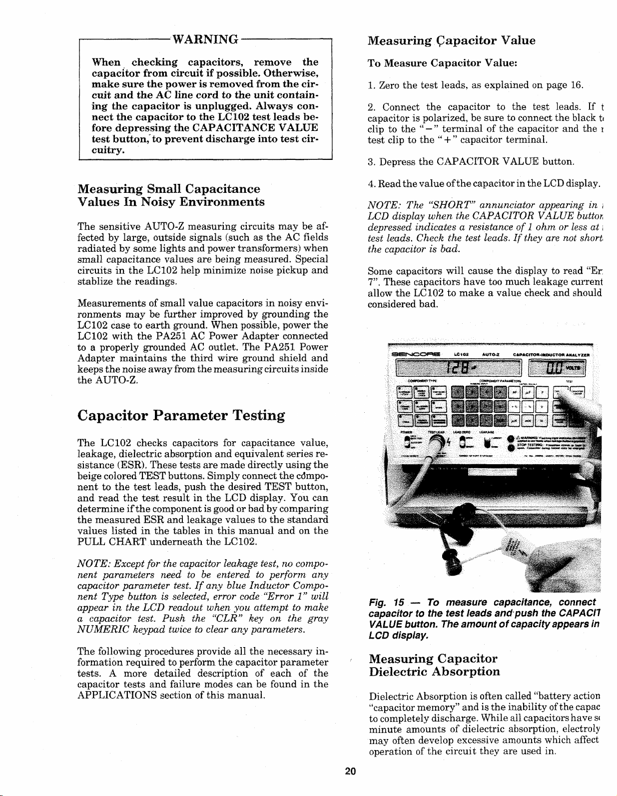
Fig. 15 — To m easure capacitance, connect
capacitor to the test leads and push the CAPACH
VALUE button. The amount o f capacity appears in
LCD display,
Measuring Capacitor
Dielectric Absorption
Dielectric Absorption is often called “battery action
“capacitor memory” an d is the inability of the capac
to completely discharge. While all capacitors have s<
minute amounts of dielectric absorption, electroly
may often develop excessive amo unts which affect
operation of the circuit they are used in .
20
Page 21
To check a capacitor for dielectric absorption, press the
DIELECTRIC ABSORP button and compare the value
to the cha rt. A fully automatic GO OD/BAD test may
also be u sed to test for dielectric absorp tion. This test
is explained on page 26.
To measure capacitor dielectric absorption:
1 . Connect the capacitor to the test leads. If the
capacitor is polarized, connect the red test clip to the
“ + ” capacitor terminal and the black test clip to the
“ — ” terminal.
2 . Depre ss the DIELECTRIC ABSORP button. A “ - ”
will appear and slowly mov e through the display indi
cating that the test is in progress.
3. Read the percentage of dielectric absorption on the
display.
4. Compare the measured D/A to the amount listed in
Table 1 for the capacitor type you are testing to deter
mine if the capacitor is good or bad.
N O T E : D e pending on the capacitor’s value, type a n d
actual D/A, the LC 1 0 2 may, in a few cas es , take u p to
10 seconds to display a reading.
Maximum Allowable Percent Of D/A
ch arts. The capacitor is good if the measured leakage
is below the amount shown in the chart. A fully automa
tic GOOD/BAD test may also be used to check
capacitors for leakage. This test is explained on page 26.
Ι Π Γ Ι Π V0LTS
I U U.U
o m p q n e n t p a r a m e t e r s
l e a k a g e
#
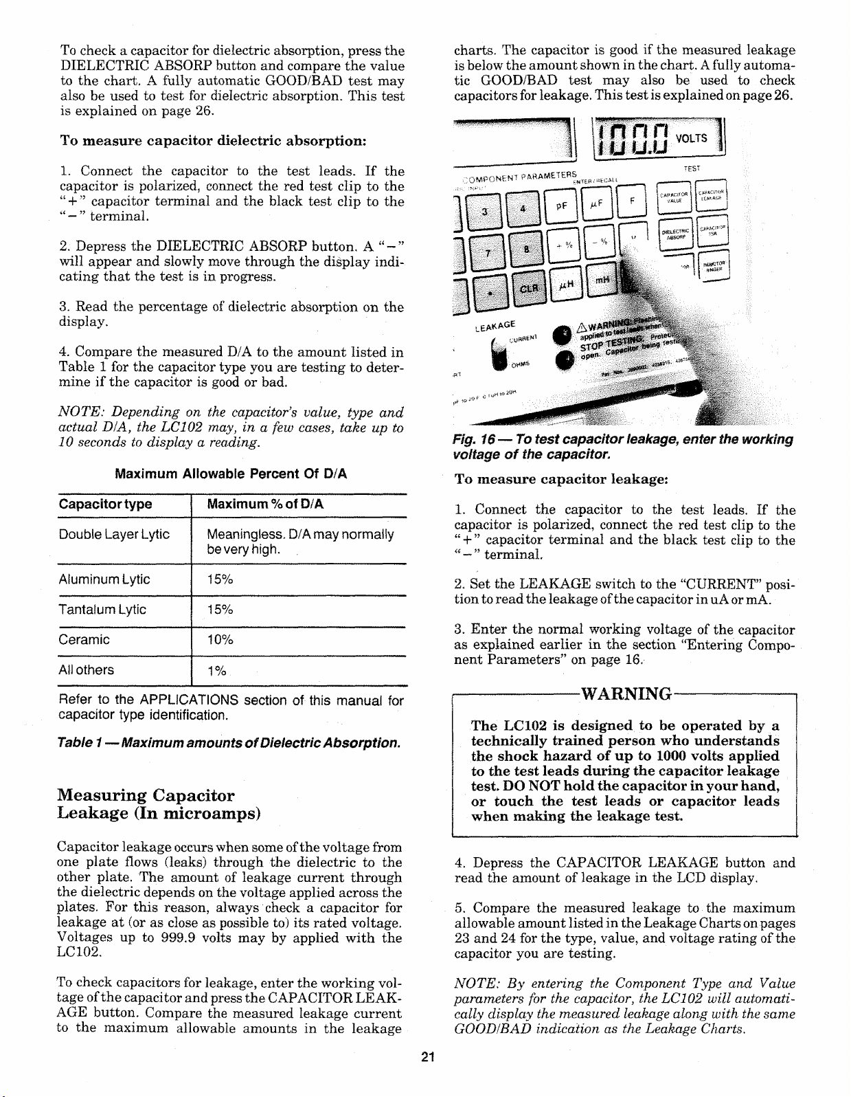
Fig. 16— To test capacitor leakage, enter the working
voltage o f the capacitor.
To measure capacitor leakage:
Capacitor type Maximum % of D/A
Double Layer Lytic Meaningless. D/A may normally
be very high.
Aiuminum Lytic 15%
Tantalum Lytic
Ceramic 10%
All others
Refer to the APPLICATIONS section of this manual for
capacitor type identification.
Table 1— Maximum amounts o f Dielectric A bsorption.
15%
1%
Measuring Capacitor
Leakage (In microamps)
Capacitor leakage occur s when some of the voltage from
one plate flows (leaks) through the dielectric to the
other plate. The amount of leakage current through
the dielectric depends on the voltage applied acr oss the
plates . For this reason, always check a capacitor for
leakage at (or as close as possible to) its rated voltage.
Voltages up to 999.9 volts may by applied with the
LC102 .
1 . Connect the capacitor to the test leads. If the
capacitor is polarized, connect the red test clip to the
“ + ” capacitor terminal and the black test clip to the
terminal.
2. Set the LEAKAGE switch to the “CURRENT” posi
tion to read the leakage of the capaci tor in uA or mA.
3. Enter the normal working voltage of the capac itor
as explained earlier in the section “Entering Compo
nent Parameters” on page 16.
------------
^-------WARNING-------------------
The LC102 is designed to be operated by a
technically trained person who understands
the shock hazard of up to 1000 volts applied
to the test leads during the capacitor leakage
test. DO NOT hold the capacitor in your hand,
or touch the test leads or capacitor leads
when making the leakage test.
4. Depres s the CAPACITOR LEAKAGE button and
read the amount of leakage in the LCD display .
5. Compare the measur ed leakage to the maximum
allowable amou nt listed in the Leakage Charts on pages
2 3 and 24 for the type, value, and voltage rating of the
capacito r you are testing.
To check capacitors for leakage, enter the working vol
tage of the capacitor and p ress the CAPACITOR LEAK
AGE button. Compare the measured leakage current
to the maximum allowable amounts in the leakage
N O T E : B y entering the Comp o n e n t Type a nd Value
parameters for the cap aci tor, the L C 10 2 wi ll automati
cally display the measured leakage along with the same
G O O D IB A D indication as the Leakage Charts.
21
Page 22

Voltage will be appl ied to the capacitor as long as the
CAPACITOR LEAKAGE button remains depressed,
and the leakage reading s will decrease as the capacitor
continu es to charge. Some capacitors may take a few
seconds to cha rge up to the applied voltage and may
cause the display to overrange with a flashing “88 .8 8
mA” displ ay. Continue to depr ess the CAPACITOR
LEAKAGE button until the leakage reading drops
below the maximum allowable amount listed in the
Leakage Chart.
When the CAPACITOR LEAKAGE button is released,
the LC102 discha rges the capacitor through a low
value, high wattage resist or. The LC 102 contains safety
circuits which sense the voltage across the test leads.
Therefore, when you release the CAPACITOR LEAK
AGE bu tton after checking a large value ca pacitor, or
after applying a high leakage voltage, the di splay may
show “Wait
-----
” and the STOP TESTING alarm may
activate until the voltage is gone from the test leads.
All data inp ut and test buttons will be loc ked out until
the display returns to “0 0 0 0 ”.
Leakage In Paper, Mica and Film Capacitors
Paper, mica and film capacitors shou ld have extremely
small amounts of leakage. Measuring any leakage
when che cking these types of capacitors indicates a bad
component. The leakage reading may take 1-2 second s
to show an ac curate display while the capaci tor charges.
Leakage In Ceramic Capacitors
Leakage in cera mic capacitors is generally very low.
Ceramic dis c capacitors, however, may have small
amounts of nor mal leakage. Ceramic disc cap acitors
with voltage ratings above 50 WVDC should have les s
than 1 uA of leakage. Some discs with working voltages
less than 50 WVDC may have a lower insulation resis
tance, and therefore may show somewhat more leakage,
depending upon manufact urer. In general, a 10 WVDC
ceramic disc capacitor may show a s much as 16 uA of
leakage, and 25 WVDC ceramic disc may read up to
2 .5 uA of leakage and still be considered good.
Leakage In Aluminum Electrolytics
Because of their larger value and higher leakage
characteristics, aluminum electrolytic capac itors may
take several seconds to charge. The LC1 0 2 display may
overrange (flashing 8 8 . 8 8 mA display) indicating the
charging current is greater than 20 mA while the
capac itor is charging. Table 2 shows the ap proximate
time that you can expect the LC102 to overrange for a
given capacitor value and applied voltage. After the
LC1 0 2 stops overranging, the current will drop in prog-
ressivly smaller step s as the capacitor charges. When
the cap is fully char ged, the leakage readings will
change just a few digits u p or down. You do not n eed
to wait until an electrolytic capacitor is fully charged
to determine if it is good. Simply keep the CAPACITOR
LEAKAGE button dep ressed until the leakage reading
falls below the maximum amount shown in the Leakage
Charts.
C a p a c it y ju F )
Table 2 — Meter Overrange time versus capacii
value and applied voltage.
Leakage In Tantalum Electrolytics
Tantalum electrolytic capacitor s have much l ov
leakage than aluminum electrolytics of the same s:
and voltage rating. Therefore, tantalum lytics will gj
a leakage reading in a much shorter time than
aluminum lytic - typically within 2 to 5 seconds. Co:
pare the measured leakage with the amounts shown
the leakage charts to determine if the capacitor i s go
or bad.
Leakage In Non-Polarized
Electrolytics
Electrolytic ca pacitor s which are non-polarized shou
be check ed for leakage in both directions. This requ ir
that you measur e leakage twic e, reversing the LCli
test lead conn ections for the second test. The maximu
allowable leakage for a non-polarized electrolytic
either direction is twice that of a similar polarized el*
trolytic of similar capacitance value and voltage ratinj
Leakage charts
The following leakage chart s list the maximum amou:
of allowable leakage for the mos t common aluminu
electrolytics and dipped solid tantalum capacito r
These charts are also duplicated on the PULL CHAS
below the LC102. Good capacitors (a s far as leakage
concerned) will measur e lower than th e amounts shov
in the Leakage Charts. When measuring leakage, yc
do not need to wait for the readings to drop to zer o i
to its lowest point. The capacitor is good for any l eaka^
reading which is lower than the amount shown in tt
chart.
Leakage values sho wn in Table 3 for aluminum eie
trolytic capaci tors are the worst -case conditions, J
specified by the Electronic Industries Association (Εΰ
standard RS-395. The values ar e determined by tt
formulas: , L = 0.05 x CV (for CV products less tha
1000 ) or L = 6 x square root of CV (for CV produci
greater than 1000. (The CV pr oduct is equal to th
capacitance value multiplied by the voltage rating)·
22
Page 23

The tantalum capaci tor leakage values listed in Table
4 are for the most common type of tantalum capacitor s
— dipped solid, type 3.3 . These values are specified by
EIA standard RS-228B, following the formula: L = 0.35
x square root of CV . In a few applications outside of
Maximum Allowable Leakage (in M icroamps)
Standard Aluminum Electrolytic Capacitors
Capacity
in uF 1.5V
1.0
1.5
2.2
3. 3
4.7
6.8
10
15
22
33
47
68
100
150
220
330
5
5
5
.....
5
5
5
5
5
5
5
5
5
8
11
17
25 50 267
470
680 19 2
10 0 0 232 329
1500 285
22 00
345
3300 422 597
4700 504
6800 606
10 000
735 1039 1470
15000 900
22000
33000
1090 154 1
1335
47000 1593
56000
68000
10 0 000
150000
220000
1739
1916
2324
2846
34471
S.OV
3.0V
5
5
5
5
5
5
5
5
5
5
7
10
15
23
33
225 319
27 1
402 569
487;
712 1008 1301 1593 1840 2057
857
1212 1565 1916 2213
1800
1273
2180
2670
1888
3186 4113 5038
2253
3478
2459
2710
3832 4948 6060
3286 4648
5692
4025
4874
6893
10V
5
5
5
5
5
5
5
5
7
10
14
20
30
45
218 281 345
383
465
689
844
1090
1897
2324
2814
Γ 3447
4490
6000
7348
8899
15V
20V 25 V 35V
5
__
5
5
5
5
8
11
17
24
34
50
232
3451
411
495
600
735 900
890
5
5
5
11
17
5
5
5
5
5
5
5
5
7
5
8
10
15
2 2 ~
25
35
192
232
285
422
504
606 700 782
735
1090
1335
2324
2846 3286
3447
4221
5499 6350 7099 8400
7348 8485
9000
47
22 1
268
329
398
487
582 650
849
1039 1162
1259 1407 1665 1990
15 41
2683
3980
4874
5817 6504
6997
1723 2039
2474 2927 3499 4948
3000 3550
3674 4347
4450 5265
5450 6448
7823
9487
ί I I I I
13
19
28
41
206
247
300
367
445
545
949
consumer service, tantalum capacitors other than type
3.3 may be en countere d. Refer to the manufacturers
specifications for the maximum allowable leakage for
these special capa citor types.
50V
5
5
5
5
5
6
9
5 11
6
8
12
18 50
26
199
39
204
243
293
355
435
526 629 890
645 7 71 1090
770
926
1122 1342
1375
2434 2909 4113
7695 9198
9256
044
29 1 411 582
350
424
520
920 130 1
1106
1643
2437
4243 6000 8485
5196
6293 8899
7707
100V
5
5
8
12 23
17
38
1565
1897
2324
2814
3447 4874 5970 6893
7348
200V
5
10
15
8
22
17
33
47
34
22 1
268
232
281
345
495
600 849 1039
735 1039 1273
329 402
398 487 563 629
487
700
1259
154 1
1840 2253
2213
2683
3286
3980
5817
6997
400V
300V
20
15
23~
30
44
33
50 218
225 260
27 1
313
379 424
329
465:
597
689
712
823
990
857
1200 134 2
1470
154 1
1780
2180
1888
2602
2710
3129
3286
3795 4243 4648
4648
4025
4874
5628
8227
7125
8570 9895
.......Γ.
....._ j
.... ....
500V
600V
25
38
199 218~
244 267
29 1
350 383
520
77 1
920
1106
1643 1800 2324
199 0
2437
2909
3499 3832
5196
6293
7707
9198
30
45 232
319
465 600
569 735
689
844
1008
1212 1565
1470 1897
2180
2670
3186
5692
6893
8443
j
_
I i
I ........ί
.........
— l
1000V
50
281
. 345
411
495
890
1090
130 1
2814
3447
4113
4948
6000
7348
8899
.........
NOTE: No industry standards are available for component vaiues in the shaded areas. These vaiues have been
extrapolated from existing standards and manufacturers data. Ail vaiues not shaded are based on existing EIA
industry standards.
Table 3 — Max imum allowab le leak age for aluminum e le ctrolytics per EIA standards.
23
Page 24

Dipped Solid Tantalum Capacitors
Capacity
1.5V 3.0V 6.0V
1.0
1.0 1.0
1.5 1.0
2.2 1.0 1.0
3.3 1.0
4.7 1.0
6.8 1.0
10 1.6
15
22
2.2 2. 2
2.8 2. 8 2 , 8 3.0
33 Γ 3,4
47 4.0
68
100
150
22 0
5.0 5.0
.......
7 ΤΊ
20
330 20
470
24
680 29
10 0 0
1500
22 0 0
3300
4700
6800
10 0 00
35 35 35
43 43 43
52 52
64 64 64 64 78 90
76
91 91
■·' . 111;:
15000 136:
22 000
: 164
33000 201
47000 240)
68000 289
10 000 0
150000
2000 00 495
350
: 429
1.0
1.0
Γ i.o
1. 0
1.6 1.6
3.4 3.4 5.0 7.5
4.0 4.0 10 10
10 10
15 15 20 20
15
20
20 2 0
24 24 24 29 34 38 45
29 29
76 76 76 93
111
136
CO
IT—.
201
■ 240
240
289
350
429 429
495 495
10V
1.0 1.0 1.0
1.0
1.0 1.0 1.0
1.0 1.0 1.0 1.0
1.0 1.0
1.0
1.0 1.5 2.0
2.0
2.2 2.5
5.0
15 15 20
10 15 20
20 20 20 23
20
29
35
43 53 61 68
52 52 64 73
91 91 112 129
11 1 136 157 175
11 1
136 ■ 36 166
164
164
20 1
201
240
289
289
350
350
429
495 606
Maximum Allowable Leakage (In Microamps)
20V 25V
15V
1.0 1.4 1.0
1.5
1.0
1.5 2. 0 2.6
2.5 3.0 3.0
2.5 3.0
4.0
3.0
5.0 9.5 10
15 10
15 15 16
20
19
25 28
35V 50V
1.0
1.8
2.2 2.0
1.0 1 .0
1.2
2.5
4.0
7.0
5.0 7.8
5.0 9.6
10
11 14 20 28
15 17 20
17
21 25
21
26 31
32 38
100 V 200V
4. 9
3. 5
6.1
4. 3
2.0
7.3
5.2
2.0
6.4 9.0 11 13
3.0
7.6
3.5
6.5 9.1
11 19
11 13 15
13 16 18 20
14 19
12 16 23
34 42 48
24
17
41 50
29
25 35
30 43
49 61 70 78 86
6 1
37 52 73
64 90 110 127
45
54 76 107 13 1
129
41 46
35
49
43
55
82 97 116
10 1 119
107 120 142 170
144 17 1
214 254 303
192
232 260
20 1
246 284 318
294 339
353
429 495 553
535^ 606 678
379 449 537 759
408 456 540
734
783
54 65
65 78
80
142 201
204
207 247 350
307 367 519 i: 734
376 450 636
645
655
802
971
783
959
1100
91
11 1 157
96 136 192 235 271 303 332 429
164 232
284 348
240 339
289 408
495
429 606 742
899 1101 1272 ■ ■142 2
1073
12 91 ί 1581 ■1825
913
1107 1565
1917 2348 2711
1356
2210
1570
300V
6.1 7.0 7.8 8 . 6
7.4
500V 600V 1000V
400V
8.6 9.6
11
9.0 10 12 13
14 16
17 19
22
22 25 27
23 27 30 33
28
37 40 52
33
35 40 45 49 64
54
59 76
_ _
71
74
58
86 96 105
90 104 116 127 164
204
367
450
645
156 . 2 01
186
224 289
27 1
402 519
492
707
1557
2236 2886
271 1 3500
3320
3830
• : ■ 142
: 152 170
158
192
284
416 480 537 588 759
500 577
606 700 783 857
899 1038
131V
1917
2710
183
221 247
328
; 402
857 959 1050 1356
11 61 1272 1642
1518 1697 1859
2041
2214 2475
3031
3130 3500
11
14
20
24
29
35
43
91
111
136
240
350
636
913
1107
201 1
2399
4287
519 1
NOTE: No industry standards are available for component vaiues in the shaded areas. These vaiues have been extrapolated from existing standards
and manufacturers data. Ali vaiues not shaded are based on exis ting EiA industry standards.
Table 4 — Maximum allowable leakage for solid tantalum electrolytics per EIA standards.
Measuring Capacitor
Yet, as far as the circuit is concerned, the DC loadi
is the same.
Leakage (In Ohms)
The LC102 uses a regulated DC power supply to provi
At times it is useful to know the amount of capacitor
leakage in terms of resistance. For example, it is often
easier to visualize what effect a 1 Megohm resistor will
have on a high impedance circuit than it is to translate
the effect of a capacitor having 1 microamp of leakage.
voltages for checking capacitor leakage. Because a I
voltage is used, the leakage currents can easily be co
verted to a resistance. Placing the front panel LEA-
AGE switch in the “OHMS” position allows the LCT
to display leakage current in ohms.
24
Page 25

To measure capacitor leakage in ohms:
1. Connect the capacitor to the test leads. If the
capacitor is polarized, con nect the red test clip to the
“ + ” capacitor terminal and the black test clip to the
“ - ” terminal.
2. Set the LEAKAGE switch to the “OHMS” position
to read the leakage current in ohms.
3. Enter the normal working voltage of the capacitor
as explained earlier in the section “Entering Compo
nent Parameters” on page 16.
!
----------------------
WARNING
-----------------------
The LC102 is designed to be operated by a
technically trained person who understands
the shock hazard of up to 1000 volts applied
to the test leads during the capacitor leakage
test. DO NOT hold the capacitor in your hand,
or touch the test leads or capacitor leads
when making the capacitor leakage test.
BHM CORE
1X 10² AUTO-Z CAPACITOR.I HOUCTOR AHAiYZCJl
4. Depre ss the CAPACITOR LEAKAGE button and
read the amount of leakage resistance in the LCD dis
play.
Fig. 17 — Place the LEAKAGE sw itch in the “ohm ”
position to measure leakage resistance.
Measuring Capacitor ESR
Fig. 18 - Depress the ESR button and read the amount
of ESR on the LCD display.
To measure capacitor ESR:
1. Zero the test le ads, as explained on page 16.
2. Connect the capacitor to the test leads. If the
capac itor is polarized, be sure to connect th e bl ack test
clip to the “ — ” terminal of the capacitor and the red
test clip to the “ + ” capacitor terminal.
3. Depress the CAPACITOR ESR button and read the
amount of ESR in ohms on the digital disp lay.
4. Compare the measured ESR to the value listed in
the following ESR tables for the capacito r type, value,
and voltage rating of the capacitor you are testing.
NOTE: By entering the component type , working vol
tage, and value parameters for the capacitor, th e LC1 02
will automatically display the measured ESR along wit h
the sam e GOODIBAD indication as t he ESR ta b l es.
Equivalent Series Resistance (ESR) oc curs when a
capacitor develops abnormally high internal resistance.
The LC102 tests capacitors for abnormal amou nts of
internal resistance using a patented ESR test.
To test a capacitor for excessive ESR, simply press the
CAPACITOR ESR button a nd compare the measured
ESR to the maximum allowable ESR listed in Table 5
for aluminum electrolytic capacitors , and Table 6 for
tantalum capacitors. A fully automatic GOOD/BAD
test may also be used to test capacitors for excessive
ES R. This test is explained on page 2 6.
25
Page 26

Maximum Allowable ESR (in Ohms)
Standard Aluminum Electrolytic Capacitors
CAPACITY! I
in uF j 1.5V I 3.0V
1.0 663
1.5
2.2
3. 3
442
302
201
4.7 141-
6.8
10
15
22
33
47
68
100
150
220
330
470
680
10 0 0
1500
2200
3300
4700
6800
10 0 00
15000
22000
33000
47000
56000
98
66
44
3 iP
20
14
9.76
6.63
4.42
3.02
2.01
1.41
.976
.663
.442
.302
.201
.141
.098
.066
.044
.030 .030
.020
.014
.012
68000 .010 .010
6.0V
663
442
302
20 1
14 1
98
66
44
30
20
14
9*76:
6.63
4.42.
3.02
2.01
1.4 1
.976
.663
.442
.302
.20 1
.141
.098
.066
.044 .044 .044 .031
.020 .020 .020
.014
.012
10V
663
663
442
442
302 302
141
201
141
201
98
66
44
30
20
14
1.41
.442
.302
9.76 6.83
6.63
4.42 3.10
3.02
2.01
1.41
.976 .683
.663
.442
.302
.201
9.76
6.63
4.42
3.02
2.01
.976
.663
.201
.141 | .141
.098 .098
.066 .066 .046
.030 .030 .021
.014 1 .014
.012 .012
.010 j .010
....
15V j 20V 25V 35V
464 464
310
211 2 11 211
141
99
98 68
66 46
44
30
31 31
21 21
20 14
14
9.88
4.64
2.11
1.41 1.41
.988
.464
.310
.211
.141 .141
.099
.068
.014
.010
i
..
310
141
99
68
46
14
9,88
6.83
4.64
3.10
2.11 2.11
.988
.683
.464
.310
.211
.099
.068
.046
.031 .03 1
.021
.014
.010
464
464
221 221
310
151
141 101 101
7 1
99
68 ! 49
33
46
22 2 2
31
21 15
14 ί 10
9.88 7.06
4.88
6.83
4.64
3.32
2.21
3.10
1.51
1.01
1.41
.706
.988
.488
.683
.332
.464
,221
.310
.211
.151
.141
.101
.071
.099
.049
.068
.033
.046
.022
.015
.021
.010
:oi4
.010
!
50V 100 V 200V 300V
332
151
332
177
121
265
177
121 121
265
177
80 80
56
71
49
33
39 39
27
56
27
18 18
15
10
7.06
4.88
3.32
2.21
1.51
1.01
.706 ! .565
.488 j .390
.332 I .265
.221
.151
.101
.071
.049
.033
.022 .018 .018 .018
.015 .012
.010
12 12
8.04 8.04
5. 65 5.65
3.90 3. 90
2. 55 2.65
1.77 1.77
1,21
.804 .804
.177
.121
.080
.056 .056
.039 .039 .039
.027 .027
8.04
5.65
3.90
2.65
Hl77~ 1.77
1.21 1.21
1.21
.804 .804
.565 .565
.565
.390 .390 .390 .390
.390
.265 .265
.265
.177 .177
.177'
.121 .121
.080 .080 .080 .080 .080
.080
.056
.027
.012 .012 .012 .012
.012
400V
265 265
177
121
80
80
56
56
39
39
27
27
18
18
12
12
8.04
5.65
3.90
2.65
.121: . .121
.056 .056 .056
.039
.027 .027 .027
.018
600V I 1000V
500V
265
177
177
121
w]
80
80
56
56
39
39
27 ! 27
27
18
18
Ϊ2 Ί
12
8. 04
8.04
8.04
5.65
5.65
5. 65
3.90
3.90
3. 90
2. 65
2.65
2.65
1.77
1.21.
.804 .804
.565
.265
.177
. .121
.039
.018 .018 .018
1.77
1.77
. 1.2 1
1.2 1
.804
.565
.565
.390
.265
.265
1 ?7
.177
.12 1
.056
.039 .039
.027
.012
265
177
121
80
39
18
12
NOTE: No industry standards are ava ilable for component vaiues in the sha ded area. These values have been extrapolated from existing standards
and ma nufacturers data. Ail values not shaded are based on existing EIA indus try standards.
Table 5 — Maximum allowable ESR for aluminum electrolytics per EIA standards.
Capacitor Automatic
GOOD/BAD Testing
formulas in the AUTO-Z memory are the same as those
The LC102 AUTO-Z can automatically display a
“GOOD/BAD” indica tion for capacitor parameter test s.
The automatic tests are much faster than manual
parameter tests, since you do not have to look up the
result in a chart, or interpolate between listed values.
The LC102 compares the measured values of dielectric
absorption, leakage, and ESR to tables and formul as
store d in its micr oprocesso r memory. The tables and
printed in this ma nual, and are based on EIA stand ards
and manufacturers data. Not every parameter for some
capaci tor types are specified by EIA standar ds or man
ufacturer’s data. The LC102 will not pr oduce a “GOOD/
BAD” display for capacitor parameters not covered by
industry acc epted stand ards. The capaci tor types and
parameters which will produce a “GOO D/BAD" indica
tion are listed in Table 7.
26
Page 27

Dipped Solid Tantalum Capacitors
CAPACITY
inuF
1.5V | 3.0V 6.0V
1.0 133 133
88.4 I 88.4 88.4 53.1 53.1 53.1 ΐ 53,1
1.5
2.2 60.3 60.3
40.2 40.2 40.2
3.3
4.7 28.2 28.2
19.5 19.5 19.5
6.8
13.3 13.3 13.3 7,96
10
15 8.84
22 6.03 6.03 6.03
33
8.84 8.84 5.31 5. 31 5.31
4.02 4.02
60.3 36.2
28.2 16.9 16.9
4.02 2.41
10V
79.6 79.6 ί 79.6
133
24.1 24.1
11.7 11.7
3.62 3.62 3.62
47 2.82 2.82 2.82 1.69 1.69
68 1.95 1.95
100 1.33 1.33
150 0.8 8 0 . 8 8 0.8 8
22 0 0.60 0.60 0.60
330 0.40 0.40
470 0.28 0.28 0.28
680 0. 2 0
10 0 0
0.13
1500 0.09 0.09
2200 0.06
3300
0.04 0.04 0.04
4700 0.03 0.03 0.03
6800
0.0 2 0 . 0 2 0.0 2 0.02
1. 95 1,17
1.33 0.80 0.80 0,80 0.80
0.8 8 0.88 0.8 8 0. 88 0.53
0. 60 0.60 0.60 0.60
0.40 0.40 0.40 0.40
0. 28 0.28 0.28 0.28
0.2 0 0.2 0 0. 2 0 0.20
0.13 0.13 0. 13 0.13
0.13
0.09 0.09 0. 09 0.09
0.06 0.06 0.06
0.04 0.04
0.03 0.03 0.03 0.03
Maximum Allowable ESR (in Ohms)
I I
15V I 20V I 25V 35V 50V
66.3 66.3 66.3 66.3 66.3 66.3 66.3 66.3 66.3
79.6
100V 200V I 300V | 400V 500V 600V 1000V
44.2 44.2 44.2 44.2 44.2 44.2 44.2 44.2
36. 2 36.2 36.2
24.1 24,1
16.9 16.9
11.7 11,7
7.96
7,96 7.96 7.96
30.1
20,1 20.1 20.1 20 .1 20.1
30.1 30.1 30.1 30.1 30.1 30.1 30.1
14,1 14.1 14.1
11.7
11.7 11.7 11.7 11.7 11.7 11.7
11.7
7.96
7.96 7.96
5.31 5.31 5.31 5.31 5.31
3.62 3.62 3.62 3.62 3.62 3.62
1. 69
1.69 1.69
2.41
3. 62 3,62
2,41
2.41 2.41 2.41 2.41 2.41
1.69 1.69
1.17 1,17 1.17 1,17 1.17 1.17
0,80 0.80 0.80 0. 80 0.80
0.53 0.53 0.53 0.53 0.53
0.36 0.36 0.36 0.36 0.36
0. 40 0.24 0.24
0.24 0.24 0.24
0.17 0.17 0.17
0. 2 0 0.2 0 0,12
0.1 2 0.12 0.1 2 0.12 0.12
0.13 0.08 0.08 0.08
0. 09 0.05 0.05 0.05 0.05
0.06 0.06 0.06
0.04 0.04 0.04 0.04
0.04 0.04 0 . 0 2 0.02 0. 02 0.02 0. 0 2
0.0 2 0.0 2 0.02 0.0 2
0. 02 0.02 0 .02 0.01 0.01
0.01
20.1
20.1
14.1 14.1 14.1 14.2
7.96 7.96 7.96
5. 31 5. 31
2,41 2.41
5.31 5.31
2.41 2. 41 2.41
1.69 1.69 1,69 1.69
1.17 1.17 1.17
0.80
1.17
0.80
0.53 0.53 0.53
0.36
0.36 0.36 0.36
0.24
0.24
0.17 0.17 0,17 0.17
0.12 0 . 12
0.08 0.08
0.08 0.08 0.08
0.05 0.05 0.05 0.05
0.01
0.04 0.04
0. 0 2 0.02 0 . 02 0 . 02
0.01
0. 02
0.01
0.04 0.04
0.02
0,01 0.01
44.2
30.1
20.1 ■ 2 0. 1
14.1 14.1
11.7
7.96
7.96
5.31
3.62 3.62
1.69 1.69
1.17
0.80
0.24
0.17
1.17
0.80
0.24
0.17
0.12
0.08
0.05
0.04
0. 0 2
0. 02
0. 02
0.01
NOTE: No industry stan dards are available for component valu es in the sha ded are as. These values have been
extrapolated from exis ting standard s and manufacturers data. Alt va iues are base d on existing EIA industry
standards.
Table 6 — Maximum allowable ESR fo r dipped solid tantalum electrolytics per EIA standards.
ΠΎ
Page 28

CAPACITOR TYPE TESTS TO PERFORM
Vaiue Leakage D/A ESR
Aluminum Lytic X
Double Layer Lytic
Tantalum
Ceramic
All other caps
X
X X X
X X
X
X X
X
X
X
(paper, film, mylar, etc.)
Table 7 — The LC102 w ill provide an automatic GOODIBAD test of the capacitor parameters shown here.
To perform an automatic GOOD/B AD tes t, yo u must
enter the capacitor type, capacitance value, and voltage
rating of the capacitor to be tested so the LC102 can
determine the GOOD/BAD limits. If you desire to grade
capacitors according to value, you must also enter the
desired “ + ” and “ - ” value tolerances. The value toler
ances, how ever, do not need to be entered for automatic
GOOD/B AD tests of leakage, ESR, or dielectric absorp
tion.
TEST CAP
Cap. Value
Cap. Leakage
Cap. ESR
Cap. D/A
VALUE
X
X
X
X
+ %
X
- %
X
CAP
VOLTAGE
X
X
X
COMPON.
TYPE
X
X
X
N O T E : Th e leakage t est function m a y require from 4 to
8 display updates for the leakage value to se tt le be fo r e
a G O O D / B A D indication is displayed.
X
X
Table 8 — These parameters m ust be entered into the
AUTO-Z for complete GOOD/BAD test o f a capacitor.
To perform an automatic GOOD/BAD capacitor
test
1 . Zero the test leads.
2. Conn ect the capacitor to the test leads..
3. Place the LEAKAGE switch in the “CURRENT” pos
ition. The LC102 will not give a GOOD/BAD reading
with th e switch in the “OHMS” position.
4. Enter the componen t type, value, and voltage rating
of the capacitor to be tested. (Refer to the se ction “En
tering Component Data” on page 16.)
5. To grade c apacitors according to value, enter the “ + ”
and “ - ” value tolerance.
6 . Push the des ired capacitor TEST button.
7. Rea d the test result in the LCD along with the GOOD/
BAD indication.
Fig. 20 - The LC102 provides an automatic GOOD/BAD
component indication.
8 . The display must show a “GOOD” reading for all of
the tests listed in table 7 under the type of capacitor
being tested.
28
Page 29

Inductor Testing
Fig. 21 — Controls used for inductor testing.
The LC102 AUTO-Z measures the true inducta nce of
coils using a fast, reliable patented test. Coils from
.luH to 19.9 9 H are automatically measured for value
by connect ing the test leads and pressing the test but
to n. A patented Ringer test dynamically checks the “Q”
of the coil and provides a proven GO OD/BAD check.
Balancing Out Lead Inductance
The LC10 2 test leads have a small amount of induc
tance which must be balanced out for greater accuracy
when measuring inductor values smaller than 1 0 0 0
uH. This lead inductance is balanced out with the
LEAD ZERO switch.
To balance out test lead inductance
1. Connect the test leads to the TEST LEAD input jack
on the LC102.
2 . Connect the red and black test cl ips together.
3. Move the LEAD ZERO switch to the “SHORT” pos
ition, and release when a begins to move through
the display.
4. The test lead inductance will automatically be ba
lanc ed out for all su bsequen t inductance tests as long
as the AUTO-Z remains on.
Fig. 22 - Connect the test leads together and push the
LEAD ZERO button to “SHORT” to balance out the test
lead impedance when checking small value inductors.
N O T E : Zeroing or not zeroing the te st leads will not
af f e c t the Ringe r te st.
29
Page 30

Inductor Value Testing
Induct ors are tested for value with the LC102 by simply
connecting the inductor to the test leads a nd pushing
the INDUCTOR VALUE button . No component type
switches need to be selected to mea sure inductance
value. Make sure none of the beige capacitor type but
tons are selected, or the LC102 will only display ‘‘Error
1” when the inductor test b utton is pressed.
N O T E : Only the blue color coded L C 1 0 2 buttons are
used for inductor value t est ing .
To measure inductance value
1 . Zero the test leads.
2. Connect the inductor to the test leads.
3. Push the INDUCTOR VALUE button.
4. Read the inductan ce value on the LCD display.
N O T E : The L C 1 0 2 L C D display will read “O P E N ” if
the compone n t connected to the tes t leads has more than
20 koh m s of resistance wh e n the I N D U C T O R V A L U E
button is pressed. Ch e ck the connections t o the inductor.
If y o u are testing a multitap co il or transformer, be sure
you are connected to the proper ta p s . If the connections
are good, the inductor has a n open wind ing an d i s bad.
Inductor Automatic
GOOD/BAD Testing
shown in the LC102 LCD displa y. A shorted turn will
lower the Q of the coil, causing the LC102 display to
read “BAD” and sh ow less than ten rings.
In addition to air core coils " and RF choke s, vertical
deflection yokes, horizontal flyback transfo rmers and
switching power supply transformers are reliably
checked with the Ringer test. The LC102 automatically
matc hes the coil impedance to the necessary testing
parameters for the inductor type when the pro per In
ductor COMPONENT TYPE switch is se lected. Simply
sele ct the component type and press the INDUCTOR
RINGER test bu tton to obtain the GOOD/BAD indi ca
tion. Refer t o the APPLICATIONS section of this man
ua l for more details on inductor types.
f:0?$P0NENT TYP£
- ■
m sv
cons
Μ1:: &
ίνίΤΤ
Y O K E S 4
F L Y B A C K S
S W I T C H I N G
X F O R M E R S
The LC102 provides two GOOD/BA D tests for induc
tors. The first GOOD/BAD test is the patented Ringing
test which chec ks for sh orted turns (low Q) in the induc
tor.
The se cond LC10 2 GOOD/BAD test compares the actual
measured value of an inductor to a user-entered value
and tolerances. Both tes ts will display a GOOD/BAD
readout along with the measured parameter.
N O T E : The blue color coded T E S T a n d C O M P O N E N T
T Y P E Select buttons are used for inductor G O O D I B A D
t ests.
Checking Inductors
with the Ringer Test
A shorted turn in many coils will go unnoticed with a
value test, since the sh orted turn changes the induc
tance value only a small amount. The patented Ringer
test, however, provides a fast and accurate GO OD/BAD
indication of non -iron core coils larger than 10 uH by
checking their quality or “Q” factor. The Ringer test is
sensitive enough to detect even a single shorted turn
on a co il. The AUTO-Z measures Q by applying a pulse
to the coil and counting the number of ringing cycles
until the ringing damp ens to a preset level. A good coil
will indicate “GOOD”, an d 10 or more rings will be
Pig. 23 — The inductor COMPONENT TYPE switches
match the Ringer test circuits to the inductor impe
dance.
To perform the Ringer test
1 . Connect the coil to the LC102 test leads.
2. Select the proper inductor COMPONENT TYPE
switch.
3. Push the INDUCTOR RINGER button.
4. Read the condition of the coil as “GOOD” or “BAD”
in the LC102 LCD display.
Special Notes O n Us i ng The Ringing Test
1. D o not ring co i l s a n d transformers having laminated
iron co r e s , such as p owe r transformers, f ilter chokes and
audio output transformers. The iron core will absorb
the ringing energy an d pr oduce unreliable te st re su lts.
2. Go o d coi ls below 10 u H m a y not read “G O O D ” because
the small inductance value ma y not allow the coi l t o
ri ng . C o mpare the n u m b e r of rings t o a k n o w n good coil·.
30
Page 31

The patented Sencore R ingin g tes t is based on the Q of
the coil. Ho w e ver, the readings on the A U T O - Z m a y not
ag ree , with the Q readings obtained using a “ Q Meter”
or bridge. This is because the Ri nging te s t has been
simplified to provide a simple G O O D IB A D t e st, rather
than a frequency dependent reactance!resistance r atio .
Testing Inductor Values
Using The GOOD/BAD Test
The LC102 will automatically compare the measured
value of an inductor to its marked value and display a
good or bad result, based on the component being in or
out of tolerance. In order for the AUTO-Z to compare
the marked value to the measured value you must prog
ram the inductance value and tolerance into the LC102
using the NUMERIC keypad. Then w hen you push the
INDUCTOR VALUE button, the measu red inductance
value will b e displayed along with a GOOD/BAD read
ing base d o n the programmed tolerance.
COMPUTER INTE RFA CE
OPERATI ON
All of the LC102 AUTO-Z tests may b e totally auto
mated or incorporated into an automated test system
through the use of the IEEE 4 88 General Purpose Inter
face Bus (GPIB or RS2 32). This section explains IEEE
opera tion, but the comm ands are the same for RS232.
The LC102 is interfaced to any IEEE syst em or control
ler using the (optional) IB72 IEEE 4 88 Bus Interface
accessory. The IB72 makes the AUTO-Z a fully compat
ible IEEE instrume nt.
The LC102 may have either of two function s. As a “lis
tener” it can receive instructions from the IEEE 48 8
bus controller to change functions or ranges. The LC1 0 2
listener function s provide complete automation, as the
controller is able to send any values or tolerances
needed for good/bad testing comparisons and the con
troller can select any of the AUTO-Z test functions.
As a “talker” the LC102 can send read ings back to the
IEEE 488 bus controller as the controller requests
them.
Fig. 24 - The LC102 w ill provide a GOOD/BAD test of
inductance value if the marked value and tolerance is
program med in.
To Use The GOOD/BAD Inductance Test:
1. Zero the test leads.
2 . Connect the induct or to the test leads.
3. Enter the marked value, along with the “ + ” and
“ — ” tolerance of the inductor to be tested. (Refer t o the
sectio n “Entering Component Data” on page 16.)
C ONNECT IN G THE LC102
FOR IEEE OPERATION
The IB72 IEEE 488 Bus Interface accessory must be
connected to the LC102 AUTO-Z for IEEE operation.
The IB72 acts as a translator between the GPIB signals
and the microprocessor insi de the LC102 AUTO-Z. The
IB72 connects to the INTERFACE ACCESSORY JACK
located on the back of the LC102. The st and ard GPIB
cable then connects to the IB72.
4. Push the INDUCTOR VALUE button.
5. If the measured inducta nce value is within the prog
rammed value tolerance the “GOOD” annunciator will
come on.
6 . If the measur ed inductance value is outside the prog
rammed value tolerance, the “BAD” annunciator will
come on.
Fig. 25 - The IB72 IEEE 488 Bus Accessory interfaces
the LC102 to any GPIB system for automated opera
tion.
Page 32

When using the LC102 in a Bus system only operate
the LC102 from its AC power adapter. The power adap
ter prevents the auto-off circuits from removing powe r'
from the LC1 02 during an automated test. If the auto-
off circuits shut the AUTO-Z down, the bus controller
may become hung up in the middle of its program.
Eac h instrument in an automated bus system must be
assigned its own address in order for the controller to
send instruction s to or receive readings from one in stru
ment at a tim e. The address of the LC102 is set with
a group of miniature slide switches on the back of the
IB72. Refer to the IB72 instruction manual for details
about addresses and setting these switches.
S P E C I A L N O T E O N I E E E P R O G R A M S
The compute r progra m s or software used to automate a
system must be written for the s p e c ifi c application being
performed. T h e a m o unt of p r ogramming required de
pends on the type of IE E E 488 cont rol le r used a n d wha t
you wa n t the automation to accomplish. Most I E E E 48 8
pr o gra m min g is don e in the B A S I C computer language,
although a n y other language compatible with your co n
troller can be used as w el l . Th e examples covered in th i s
sectio n are written in B A S I C , since it is the mos t co m
monly used c omputer language for GP I B applications.
SENDING DATA TO THE LC1 02
To connect the LC102 to an automated GPIB sys
tem:
1 . Remove power to the LC1 0.2 and to the IB72.
2. Set the Bus Add ress slide switches on the bac k of
the IB72 to the address you have assigned to the LC102.
3. Connect the male DIN connector on the IB72 to the
Interface Accessory Jack on the ba ck of the LC102.
4. Connect the AC power adapters to the LCX02 and to
the IB72 and connect them to AC outlets.
5. Confirm that power has reached the units by check
ing the power LED on t he I.B72 and the digital readout
on the LC1 0 2 .
6 . Follow the instructions for your controller to load
and run the software.
As a listener, the LC102 a ccepts commands from the
controller. These commands can be used to select a
function or to send parameters to the LC102 for GOOD/
BAD comparison testing. The commands sent to the
AUTO-Z during bus operation duplicate the front panel
pushbuttons. Follow the same programming sequence
and range limits as for manual (non-IEEE) operation.
The listener codes consi st of one, two, or three charac
ters, and relate to the function being selected or the
data being entered. Most, listener codes consist only of
the cod e characters. The listener codes used to enter
data for good/ba d testing c onsist of a number, followed
by the character code.
Most controllers sen d information over the b us by
means of a “print” statement. The information to be
sent is usually placed into a variable, and the variable
is then printed to the bus, along with the address of
the instrument. Study the information with your con
troller for details abou t sending information to instru
ments. .
The codes may be sent by the controller as either upper
or lower case (capital or small) letters.
Fig. 26 - The LC102’s address is selec ted by the Bus
Address switches located on the rear of the IB72.
All data sent to- the LC1 02 must end with a linefeed
character, to b e recognized by the LC1 02. S ome control
lers automatically add this character to the end of every
string of data, while othe rs have a special function
whic h adds the linefeed when activated with a software
Q ommand. If your controller has neither of these op
tions, you can add a linefeed charac ter by storing the
character in a variable and then adding this variable
to your data befo re sending it to the bus.
Fig. 27 - shows how the linefeed ch aracter can be stored
in a string-variable called “LF$”. This variable can
then be combined with the functio n stored in “LIS
TENS” before being sent to th e bus.
32
Page 33

100 LF $“CHR$(10): REM CHR$(10) IS A LINEFEED
1 10 LI STEN$=LISTEN$+ LF$: REM ADDS THE LINEFE ED TO THE DATA
120 PR INT LISTEN!: REM SENDS THE STRING TO THE BOS
Fig. 27 - Use this routine to add a linefeed character
to the end of data statements sent to the LC102.
Value Multipliers:
These GPIB listener codes let the controller se nd com
ponent data information to the LC102 including the
ideal component value and value tolerance limits. The
codes duplicate the non-IEEE operaton of the compo
nent parameters keypad for entering component data.
The data or listener codes sent to the LC102 fall into
four groups: 1. Component Type Commands, 2 .
Value Multipliers, 3. Test Function Commands,
and 4. General Commands. All listener codes are
listed in Table 9. They are also listed in the Simplified
Operating Instructions o n the PULL-CHART unde r the
unit for ready reference.
Table 9 Component Type Commands:
Aluminum Lytics
Double Layer Lytics
Tantalum Caps
Ceramic Caps
All Other Caps
Spare
Coils
Yokes & Flybacks
Switching Transformers
Value Multipliers:
(to be preceeded by numeric value)
pF, uF , F , UH, Μ Η , H, +%, -
Test Function Commands
-%,V
Capacitor Value
Capacitor Leakage (current)
Capacitor Leakage (ohms)
Dielectric Absorption
Capacitor ESR ESR
Inductor Value
Inductor Ringer RIN
General Commands
Lead Zero Open
Lead Zero Short
LDO
LDS
No Function NFC
Control Panel On CPO
Table 9 - IEEE control co des for the LC102.
ALM
DBL
TAN
CER
AOC
SPR
COL
YFB
SWX
CAP
LKI
LKR
D/A
IND
Component Type Commands
C O M P O N E N T P A R A M E T E R S
NUMfcttlC IMPUI frNTt.P t RLCM i
PF
s
CLR
μΜ
m H
□
LEAD ZERO LEAKAGE
Fig. 28 - Dur ing IEEE operation the Value M ultiplier
Codes all ow component data to be entered into the
LC102 .
As with manual operation, each Value Multiplier Com
mand includes a number, followed by the listener code.
There are four types of Value Multipliers for IEEE
programming: 1 . Capa citor valu e, 2 . Inductor Value, 3.
Percent tolerance, and 4. Capacitor voltage. The first
three are only used for LC102 automatic GOOD/BAD
comparisons. The capacitor voltage code also sets the
LC102 power supply to the selected voltage for the leak
age test
When sending a component va lue to the LC102 it is
not necessary to send long strings of zeros to estab lish
decimal readings. Instea d, use the value multipliers uF
(microfarads) pF (picofarads), and F (farads) and the
three uH (microhenr ies), mH (millihenries), and H
(henries). For induc tors the chara cters may be sent in
upp er or lower c ase. For example, “uF”, “UF”, or even
“Uf ” will all produce the same results. The LC1 02 also
ignores any blank spaces between listener code charac
ters. This mea ns that “10UF”, “10 UF” and even “10
U F” work equally well.
The complete Value Multiplier code cons ists of the cor
rect numeric value, the Value Multiplier, and the End
Terminator. The following ex amples show valid com
ma nds, with the End Terminators not s hown:
These co des duplicate the front panel COMPONENT
TYPE switc hes and must be sent to the LC10 2 if you
want the test results t o be compared to the tables and
calculations assoc iated with the LC102 microprocessor.
As in non-IEEE operation, the LC102 uses the se to
establish the GOOD/BAD limits for the leakage, ESR,
dielectric absorption, and coil ringing test s. The good /
bad results may be in error if the wrong Com ponent
Type Comman d is sent.
NOTE: The LED on th e component type switch which
indicates if the switch is sele ct ed DOES NOT light wh e n
the LC102 is under IEEE co nt ro l.
33
Page 34

4.7uF
(enters capacitor value of 4.7 microfarad)
1 00 pF
(enters capacitor value of 1 0 0 picofarads)
15 V
(enters leakage voltage of 15 volts)
20 + %
(enters value tolerance of + 2 0 %)
5H
(enters induct ance value of 5 henries)
Setting the Leakage Voltage:
The leakage power supply must be set to the des ired
voltage before selecting a leakage te st with the LKI or
the LKR codes. The supply can be set to the nearest
tenth of a volt. The listener code simply consists of the
desired voltage followed by the letter V and the End
Terminator. For example, “100 V” sets the supply to
produce 1 0 0 volts when a leakage function is activated.
The highest voltage which can be programmed into the
LC102 is 999.9 volts the lowest is 1 volt. Attempting
to enter a voltage higher or lower than this range will
produce an Error 2 condition.
The amount of Compon ent data which nee ds to be en
tered with the IEEE Value Multiplier codes for a
GOOD/BAD test depends on the LC102 function. The
chart in Table 1 0 shows the component parameters
needed for each GOOD /BAD test. Sending additional
data to the LC102 will not affect the tests .
COMPONJ
TEST CAP IND
VALUE VALUE
Cap. Value X
Cap. Leakage
Cap. ESR
Cap. D/A
In d. Value
X
X
X
X
In d. Ringing
+ % -%
*
*
CAP
VOLTAGE TYPE
*
X X
X
X X
*
X
X
X = Must be entere d for GOOD/BAD results.
* = Tolerances are set to ze ro percent at power-up.
Table 10 - These parameters must be entered for the
LC102 to produce a good/bad t est re sult
N O T E : The LC1 0 2 wil l send good/bcid indicators back
t o t he contro ll er for each reading if a l l necessary infor
mation has been supplied. To stop the L C 1 0 2 fro m sen d
ing the “G ” or the B ” as part of i ts returned data, simply
send a zero value reading, such as “Op F ”. T h e other
Value Multipliers (such as percentages or v olt age) wi l l
remain in the L C 1 0 2 m e m or y until chan g ed or until
power is removed from the unit.
The plus and minus compon ent tolerance limits must
be sent in the correc t form. First, the number must b e
a whole number, with no decimal. Then, the percen
tages must b e within the allowable range. The largest
negative number allowed is 99 percent (99-%) . and the
largest positive number allowed is
1 0 0 perce nt
(100 + %). Numbers that are outside this range, or that
contain a dec imal, produce an Error 2 conditi on.
The leakage power supply only applies power to th e
test leads after one of the two leakage functions have
been selected with the “LKI” or “LKR” listener code .
The pow er supply automatically rem oves voltage from
the test leads when the controller send s any oth er lis
tener code , or when the front-panel button is pressed.
---------------------
Warning
---------------------
The warning LED on the front of the LC102
will flash as a reminder that a shock hazard
of up to 1000 volts may be applied to the test
leads when a leakage test is selected. Use ex
treme caution when the LED is blinking.
N O T E : W h e n not using a leakage te s t, send the lis t e n e r
code “O V ” to the L C 1 0 2 to prevent accidentally applying
a voltage t o the te st lead s .
Test Function Commands:
One of the seven listener Test Function Codes must be
sent to the LC102 before the controller can request a
reading. The selected function is cancelled by any other
listener code sent to the LC102 , meaning that a Test
Function Command must be the last listener code s ent
before a reading is requested.
The LC102 will remain in the last funct ion selected
until it receives another test function command or lis
tener code. The controller can select an LC102 test, g o
on to other instruments on the bus, and then come back
to the LC102 at a later time to reques t a reading. This
allows tes ts which require longer times, su ch as
capacito r leakage, to be used without slowing th e oper
ation of other instruments on the bus.
34
Page 35

TEST
\ naB
1 UAKA',:,
1 OICLtC T ProIj CAPACliOR
functions with a Test Function Command or when
changing component parameters with a Value Multip
lier comma nd, since any listener code clears the current
function. Sending the “NFC” comman d whe n the LC102
is not in a test function has no effect.
j INDUCTOR
le a k a g e
/‘“'s CURRENT
Test Function
Capacitor Value
Capacitor Leakage (current)
Capacitor Leakage (ohms)
Dielectric Absorption
Capacitor ESR
Inductor Vafue
Inductor Ringer
Fig. 29 - The LC102 TEST functions are selected via
IEEE using the Test Function Commands.
ί tNlDU'i TOH
Commands
CAP
LKI
LKR
D/A
ESR
iND
RIN
The LC102 starts a test from its beginning every time
it receives another Test Function Code. Therefore, if
the LC102 has been preset to a function for a delayed
reading,mak e certain that the controller does not re-
send the cod e just before a reading is taken.
General Codes:
The four general listener codes activate spe cial func
tions wh en sent to t he LC102. The codes let the control
ler instruct the LC1 0 2 to compensate for the test leads,
clear a fun ction, or return control of the LC10 2 to the
front-panel switches.
The LC102 must subtract residual effects of the test
lea ds when testing ESR, and small capacitor or inductor
val ues. The Lead Zero (LDO) and Lead Short (LDS)
listener cod es duplicate the operation of the front panel
LEAD ZERO button to null out the effects of the re
sid ual resistance, capacitance, and inductance of the
test leads and test fixture. The leads must be shorted
before sending the LDS co mma nd and opened before
send ing the LDO comma nd. If not, the test lead impe
danc e will not be compensated for,
Note: The leads can be nulled manua lly before turning
contr ol of the L C 1 0 2 over to the automated system. Sim,-
ply follow the procedures for manually nulling the ef f ect s
of the le a d s, as explained on page 1 6 . T he LC 1 0 2 will
remember the corre ct compensation unti l th e pow e r is
turned off.
The No Function Command (NFC) cancels any test that
is in progre ss and places the LC102 into the standby
mode (no button pressed). You on ly need to send “NFC”
if you want to clear a test. For example, you may wish
to turn off the capacitor value test function while you
remove one component and replace it with a different
one. It is not necessary to send “NFC” when changing
IMPORTANT
Do not disconnect or connect any components
to the LC102 after performing any capacitor
or inductor test without first sending a No
Function Command (NFC) or other command
first to clear the test function. The LC102 may
be damaged if charged capacitor, or static
voltage is connected to it. Also, a severe shock
hazard may exist to the user if a capacitor is
removed after a leakage test without first
being discharged.
The front panel switches are automatically disab led
whenever the LC1G2 receives its first GPIB c ommand
through the IB72. As a reminder of this, any LEDs
ass ociated with the COMPONENT TYPE switches will
turn off as soon as the LC 1 02 receives a GPIB c ommand.
The panel will remain locked out for all function s until
the Control Panel On (CPO) code is sent or until power
to the.LC 10 2 is removed.
N O T E : One exception is the capacitor leakage func ti on .
Depressing an y of the front-panel switches wi l l m a n u
all y un-latch the I E E E use of the leakage power supply.
READING DATA FROM THE
LC102
The LC102 will send data to the controller through the
computer interface accessory whenever the controller
sends the correct talker address and a “Talk” command.
The data returned over the bus will be the same as the
reading appearing in the LCD display.
Error messages will also be returned over the b us. The
error codes will be the same as the codes during manua l
(non-bus) operation, and are listed on page 37.
N O T E : Most contr ol le rs automatically combine the
“Talk” c o m m a n d with the instruction containing the
address, so there is not a separate st ep required in t h e
program. Consult the manu a l for t h e contr o ll er you are
using for information on it s ope ration.
Once addr essed, the LC102 sends a reading over the
bus every time it updates the reading on the LCD dis
play. The software in the controller determines how
many readings are recorded. Some applications only
ne ed a single reading, while other appli cations may
require collecting several readings in a row.
The only difference between collecting a single re ading
or collecting a series of readings is in the controller
software. If only one reading is desired, the controller
will trigger the talker function, and then wait until
one reading is received. Then the controller sends a bus
instru ction which cau ses the LC102 to sto p send ing
readings.
35
Page 36

One way to stop the LC1 0 2 from sending readings is
to simply address a different instrument on the b us
with the controller. The LC1 02 will remain in the test
functio n, but the readings will not be sent to the control
ler until the LC102Js talk address is again selected by
the controller.
N O T E : T h e LC 1 0 2 will return a Control Panel O n
(CPO) header if it is addressed to t a l k but has not re
ceived a valid l is te n er code. A N o Function C o m m a n d
(NF C ) is returned if the L C 1 0 2 has received a valid
lis t e ne r code, but h as not been given a Test Function
C o m m a n d .
A second method to stop the LC1 0 2 from sending read
ings is to send any listener code, including the No Func
tion Code (NFC), to the LC1 0 2 . This will bot h stop the
readings and place the LC102 into its standby mod e.
Always us e this method if a different component is
going to be connec ted to the LC102 .
N O T E : The LC 1 0 2 does not need (nor does i t respond
t o) the special “G E T ” (group-execute-trigger) c o m m a n d
used in some co ntr o l l e r s . It w il l begin sending resu l ts
as soon as the tal k c o m m a n d is complete.
DATA FORMAT
All data returned from the LC102 falls into a standard
data format. Each data string is 17 characters long and
contains information in four data fields. The software
can keep the entire string of characters together, or it
can separate the data into three parts for calculations
or processing.
JL-LJL2L2L2L_l_J!L2L2LJL2L2L2Lil£5H:
—.—-v.
Header Numeric Data Fieid / End
Fig. 30 - The data format returned by t he LC102 is a
string of 17 characters long.
-----------,---- - -- -- - -
GOOD/BAD Indicator
, f —
I Terminator
Numerical Data Field: The 11 spaces following the
Header (characters 4 through 14) contain the numerical
results of a talker fun ction. The va iues returned from
a test function are in scientific notation, allowing any
value to be represented with the same number of
characters. Error codes appear as a single digit (from
1 to 7) without the scientific notation.
GOOD/BAD Indicator: The single space following the
Numerical Data Field (the fifteenth character) is re
served for the results of the automatic LC102 GOOD/
BAD test s. The single letter “G” or “B” appears in this
positio n when the LC102 h as sufficient information to
determine if the reading is good or bad. If a piece of
data (such a s the tolerance or ideal value) is missi ng,
the positio n occupie d by the GOOD/BAD Indicator is
left blank.
N O T E : A leakage te s t function ma y require f rom 4 t o 8
readings for the leakage to se ttl e before providing a
G O O D / B A D indicati on.
End Terminator: All d ata ends with both a carriage-
retum (ASCII decimal 13) and a linefeed (ASCII deci
mal 10) character, as recomme nded by the IEEE 488
standar d. Many controllers respond to either character,
while others only re spond if the linefeed is present. A
few controllers, however, may stop acce pting data when
the carriage-return character is sent, leaving the
1 0 2 hung up waiting to send its last (linefeed)
LC
character. If this happens, yo u may need to put an extra
GET or INPUT statement into your program to let the
LC102 send its last character into an unused variable.
Refer to the manual for th e specific controller that you
are using for information on the end terminator it acts
on.
The four fields of the data string are: 1. Header, 2.
Numerical Data Field, 3. GOOD/BAD Indicator, and 4.
End Terminator. Each field has the same number of
characters for all test functions, allowing the sa me sub
routines to process any returned data. Here are the
details for each field of data.
Header: The first three characters identify the test
function which prod uced t he reading. The three charac
ters sent back from the instrument are usually the
same as the test function comm and s us ed to select a
function when the LC102 ac ts as a listener. These c odes
let the software identify the source of the data, confirm
that the correct funct ion is producing readings, or label
the data for future retrieval.
In certain cases, the Header identifies some special con
ditions, such as erro rs or shorted or open com ponents.
The controller software should test for these conditions
before proce ssing readings for ac curate test results, as
explained in the section Error Testing on Page 37.
SEPARATING DATA FIELDS
The BASIC commands neede d to separate the three
fields of information into separate variables are LEFT$
and MID$. The LEFT$ command can collect the three
char acters of the Header if they need to be compared
to information within the program. The MIDI com
mand is used to separate the Numerical Data Field and
the GOOD/BA D Indicator from the other results.
20 00 REH SUBROUTINE TO SEPARATE DATA INTO 3 PARTS
2010 HEAD$»LEFT$(RESDLT$ ,3)s REM FIND HEADER
20 20 ANSWER=VAL(MID${RESULT$,4 ,1 1 )); REH VALUE
20 30 G00D$-MID$(RESULTS,1 5,1): REM FIND GOOD/BAD
20 40 RETURN: REM JUMP BACK TO MAIN PROGRAM
Fig. 31 - The formatted data returned by the LC102 can
be easily separ at ed into string-variables using simple
BASIC comma nds.
36
Page 37

For example, the controller coul d place a reading from
the LC102 into a string-variable called RESULTS. Th e
sub r o u t in e i n Figure 31 can then separate the Header
into the string-variable HEAD$, the Numerical Data
into the numerical-variable ANSWER, and the Good/'
Bad Indicator into the string-variable GOOD$.
Line 2010 mov es the first 3 characters into the Header
var i a b le. Line 2020 selects the 11 characters, starting
at the fourth positi on, a nd then converts the result to
a value (with the VAL statement) before placing it into
ANSWER. Line 2030 selects the fifteenth character
and moves it to GOOD$. This subro utine can be used
to separate data from any reading into the three main
parts.
Program languages other than BASIC have similar
commands which can separate the data into its different
fields.
A DVANC ED PROGR AMMING
IDEAS
Most errors cause the LC1 0 2 to return a Header with
the three letters “ERR". A simple test for this Header
allows the program to be alerted to the error. The value
of the Numerical Data Field tells the controller which
of seven errors have occurred. The error codes are sum
marized in Table 11. Refer to the section entitled “Error
Codes’' on page 16 for a more detailed explanation of
each error condi tion. The program segment listed in
Figure 32 tests for errors and then prints a message
which indicates its cause.
200 GOSUB 2 000: REH SEPARATE DATA INTO P ARTS
210 IF HEAD$<>"ERR" THEN GOTO 300: REM NO ERROR FOUND
220 ON ANSWER GOTO 230,240,250,260,270,280,290
230 PRINT "COMPONENT TYPE SELECTION ERR OR": GOTO 300
240 PRINT "VALUE BEYOND RANGE OF UNIT”: GOTO 300
250 PRINT "VALUE BEYOND RANGE OF TEST": GOTO 300
After the data has been separated, there are many
things your program can do to process it. This section
explains how to add these refinements to your BASIC
programs. In each ca se, we will refer to the short sub
routine listing in Figure 31, with a GOSUB 2000 state
ment, resulting i n the LC102 reading being stored in
the variables HEAD$, ANSWER, an d GOOD$.
Error Testing
Your controller software should test for error conditions
(often called “error trapping”) after every reading has
been collected from the LC102 to avoid an error from
caus ing unexpe cted results. The software can either
report the error or sk ip over it, but should do one or
the other without crashing the program. If your prog
ram is particularly advanced, it may test for the type
of error (as indi cated by the error number returned in
the Numerical Data Field) and then branch to different
parts of the progra m which can take the correct act ion
to compensate for the error.
Error Description
Com p onen t Typ e s e lecti o n error
1
E nte red va lu e bey o nd r ang e o f un it
2
E ntered value beyo n d r a n g e of test
3
4 Va l ue beyond z e r oing li mit
5
No volt a ge ente r e d
6
in v alid IE EE com mand
Com ponent ou t of tes t r ange
7
260 PRINT "VALUE BEYOND ZEROING LIMIT": GOTO 300
270 PRINT "NO VOLTAGE ENTERED" : GOTO 3 00
280 PRINT “INVALID IEEE COMM AND": GOTO 300
290 PRINT "COMPONENT OU T OF TEST RANGE" : GOTO 300
300 ...(Rest of Progr am)
Fig. 32 - A simple BASIC subroutine allows any errors
to be identified .
Line 210 in Figure 32 c auses the program to jump over
the error messages for any Header excep t “ERR”. The
next line takes advantage of the ON..GOTO function
of BASIC which sends t he program to line number 230
if ANSWER = 1 , to line 240 if ANSWER = 2, etc.
N O T E : Errors detected by the LC1 0 2 do not cause a
ser vi ce request (S R Q ) on the bu s. The L C 10 2 does not
respond to ser ial or parallel polls because erro rs are sent
as part of the norm al data str i n g , instead of with a
serv ic e request.
GOOD/BAD Results
The string-variable GOOD$ in Figure 31 will contain
a single ASCII character, either G or B . The contents
of GOOD$ can be tested with simple IF statements and
us ed to produce any desired output. If the GOOD/BAD
Indicator Field is blank, the prog ram can indicate that
the result is not available bec ause the LC102 has insuf
ficient data to make a comparison. If the field contains
the letter “G” or “B”, the controller can pr int a messa ge
concer ning the quality of the part. Figure 33 lists a
BASIC subroutine which can be used to check the
GOOD/BAD test result.
Table 11 - Error codes returned by the LC1 02 during
IEEE operation.
37
Page 38

140 GOSUB 2 000: REH SEPARATE DATA IN T O PARTS
150 IF GO OD$**" " THEN PRINT "N O GOOD/BAD TEST”
160 IF GOOD$*”G" THEN PRINT "THE RESULT I S GOOD"
17 0 IF GOOD$=”B” THEN PRINT "T HE RESULT IS BAD"
180 ...{ Rest of Program)
Fig. 33 - This subroutine can be use d t o read the result
of the LC102 aut omatic GOOD /BAD test
Shorted Capacitors:
The LC1 0 2 automatically senses if a capacitor is
sho rted before performing a capacitor value test. If a
shor t is detected, the LC102 sends the letters “SHT”
as the Header Field of the returned data a nd displays
“SHORT” in the LCD display. Adding one line of prog
ram code will test for this condition. This line should
appear before any part of the software program which
depends on a value reading, so that the value test will
be skipped in case of a shorted capacitor. The program
sec tion listed in Figure 34 tests for shorts, prints an
error message on the CRT, and jumps to line 400, which
hand les the er ror.
200 GOSUB 2000: REM SEPARATE DATA INT O PARTS
21 0 IF HEAD$*”SHT" THEN PRINT "CAP IS SH ORTED ": GOTO 400
220 __(Rest of Program)...
400 ...(Er r or Handling Functions)
Fig. 34 - The LC102 retur ns a “SHT” data Header when
a shorted capacitor is tested . This sam ple subroutine
checks for the short indication.
Making Leakage Tests with IEEE:
When testing for leakage on large capacitors, the first
reading returne d by the LC102 may be out side the nor
mal leakage limits because the capacitor is char ging.
In the case of electrolytics, several readings may be
needed before the capacitor drops to a “GOOD” level,
since an electrolytic also goes through a re-forming
pro cess every time it is charged from zero. This means
that the controller software should ignore the first few
readings in order to accept a meaningful reading.
There are several ways to hand le this in the so ftware.
For example, the program c ould place the LC102 into
the leakage function (with th e “LKI” listener code) and
then set a softwear timer to insert the correct del ay
(based on the normal charging time of the ca pacitor)
before reading the leakage value. During this time, the
controller could work with other instruments on the
bus to keep the delay from slowing down other steps
in the automate d system. Rather than a fixed time
delay, the software c an be written to ignore a certain
number of readings before recording the one which is
to be checked for value.
In either case, the controller can base its decision on
whether the capacitor is go od or bad by using the
GOOD/BAD Indicator in the returned data . For the
automatic GOOD/BA D test to function the capacitor's
value, voltage, and type must be sent to the LC102
prior to the test. This allows the LC102 microprocessor
to compare the leakage readings to the internal for
mulas an d tables. The progra m, steps listed in Figure
36 can be used to report on the capacitor’s condition.
The program then jumps to line 200 for further testing.
If GOOD$ contains neither a “G” nor a “B” then the
steps from 140 to 199 take the steps needed to work
with a non-GO OD/BAD test.
10 0 ...(Program with leakage delay)
Open Inductors:
The LC102 automatically senses if an in ductor is open
(or if the test leads are not connected to the coil) before
performing an inductor value test. If an open is de
tected, the LC102 se nds the letters “OPN” as the
Header and displays “OPEN” in the LCD display. On e
additiona l program line will test for this condition .
Place this line before any portion of the program which
depends on an inductor value reading, so that the value
test will be skip ped in case of an open inductor. The
program sect ion listed in Figure 35 tests for opens,
prints an error message on the CRT, and jumps to line
300, which handles the error.
10 0 GOSUB 2000: REM SEPARATE DATA INTO PARTS
110 IF HEAD$»" O PtT THE N PRINT "COIL IS OPEN: GOTO 300
120 ...(Re st of Program)...
300 ...(Error Handling Functions)
Fig. 35 - Open test leads or an open inductor causes
the LC102 to return the data header “OPN”. This simpl e
subroutine may be used to c heck for an open condi
tion.
110 GOSUB 2000: REM SEPAR A TE DATA INTO PARTS
12 0 IF GOO D$="G' * T HEN PRINT "LEA KAGE IS OKA Y": GOTO 2 00
130 IF G00D$=" B" THEN PRINT "LEAKAGE IS B AD": GOTO 200
14 0 ...(Program steps for no G/B test) . ..
200 ...(Re st of Program)
Fig. 36 - The GOOD/BAD in dica tor Field Returned by
the LC102 can be checked to test capacitor leakage.
Making ESE Tests with IEEE:
The capacitor test for Equivalent Series Resistance may
cause unexpected program errors if your software does
not handle the returned data correct ly. Remember that
ESR tests are only valid on electrolytic capacitors with
values larger than 1 mic rofara d. Also remember that
some capacitors may have such high levels of ESR that
the value is above the measuring range of the test.
Therefore, make certain that your software tests fo r
the following condi tions.
1 . An “ERR 1.” occurs if any component type other than
ALM, DBL, or TAN has been sent to the LC102 in its
listener mode.
38
Page 39

2 . An “ERR 3” o ccurs if the capacitor under test meas
ures less than 1 microfarad.
3 . An “ERR 7” occurs if the amount of ESR is above
200 0 oh ms.
4 . The leads must be zeroed (either manually or by
using" t he “LDS” listener function) before making ESR
tes ts , or the added lead resistance m ay cau se erroneous
results.
Programming Examples
Line 10000 will be unique to each controller. Refer to
the manual for the specific controller you ar e using for
details on how it sends data to the IEEE bus.
The steps listed in Figure 37 se nd all the informati on
needed by the LC 102 to test an aluminum electrolytic
capacitor with an ideal value of 50 uF, a working vol
tage of 15 volts and a tolerance of +80% and —2 0 %.
The primary address of the LC102 is 8 . Each “GOSUB
1 0 0 0 0 ” line sends the data to the unit.
It wou ld be impossible to write a program that would
work for every LC102 user. First, there are numer ous
types of bus controllers. Additionally, dozens of per
sonal computers (PC’s) can be converte d to bus control
lers by adding a GPIB control card or expansion device.
Each PC could use any of several different GPIB ca rds.
But in a ddition to hardware differenc es, th e application
of the LC102 will be different for each bus s ystem. For
example, a Reliability Lab will run different tests than
an Incoming Inspection system will.
Several programming hints are pr ovided in this section
to help you get your LC102 bus sy stem up and runnin g.
The first examples are “building block” programs which
allow you to plug the specific details for your controller
into an LC1 0 2 AUTO-Z test program. Two compl ete
programs are included at the end of this se ctio n. Those
pro grams are ready t o run, provided y ou have the s ame
hardware for which they were written.
Sending Listener Codes
The specific steps nee ded to send listener c odes to in
strum ents on the bus depend on the controller you are
using. Some controllers only require the addition of a
special code (such as a control character) into a standard
PRINT statement. Most, however, require several addi
tional initialization steps to tell, the controller’s micro
proc essor which expansion slot or memory location con
ta ins the interface card, the ad dress of the instrument
being addressed, which method is used to address the
talkers or listeners, and so on .
This doesn’t have to complicate programming, however,
if you us e subroutines to take care of all these details.
You sim ply debug these subroutines once, and call them
eac h time you send information over the bus. Your
main program places a couple of pieces of information
into variables before turning control oyer to the sub
routine w hich, in turn, handles all the details of com
municating with the bu s.
Fig. 37 show s an example of a program which uses a
su broutine at line 1 0 0 0 0 to send information to any
instrument on the bus. This subroutin e needs two piec es
of informa tion: the listener ad dress of the instrument
and the data t o s end t o it. The primary address is placed
into the variable ADDRESS, and the data into the
string-variable CODE$ before calling the subrou tine.
Once ADDRESS has been loade d, it doe s not need to
be changed unless the controller needs to work with a
different ins trument . This is the reason line 1 0 0 is the
only one which uses the variable ADDRESS.
100
110
120 GOSUB 10 0 0 0:
130
140
150
160 GOSUB 1 00 0 0
170
180 GOSUB 1 0 00 0
190
20 0
Fig. 3 7 - This sample progra m uses a su brout ine t o
simplify s ending data over the bus to the LC102. The
subrout ine called up is unique to each controller.
ADDRESS-8·: REM PRIMARY ADDRESS OF L C 1 0 2
CODE$="50 UF'
C0DE$~'* 15V" :
GOSUB 100 00
CODE$=”ALMM:
CODE$* "80+Z·’ :
CODE$=,* 20-%’·:: REH NEGATIVE TOLERANCE
GOSUB 10 00 0
*: REH IDEAL VALUE
REH SEND VALUE TO L C 1 02
REM WORKING VOLTAGE
REM CAPACITOR TYPE
: REM PO SITI VE TOLERANCE
Sending Talker Codes
As with sending listener codes, all the s teps needed to
transfer information from the LC102 bac k to the con
troller can be done in a subroutine which is called every
time the program req uests a reading. In the example
listed in Figure 38, the subroutine is at line 1 2000. The
listener subro utine is still at line 1 0 0 0 0 .
Some controllers require a different talker and listener
address, but these addresses can be calculated by the
program . The subroutine at line 10000 calculates the
neces sary listener ad dress, while the subroutine at line
1 2 0 0 0
calculates the needed talker address from the
value already stored in the variable ADDRESS. Thus,
it is not ne cessary to place a new value into th e AD
DRESS variable.
The last line of the subroutine starting at line 12000
includes an INPUT statement which collects the LC102
reading a nd places it into the string variable RESULT!.
RESULT$ is then processe d through an other su b
routine to separate the da ta into its three parts.
39
Page 40

210 CODE$**” C AP": REM LISTENER CODE FOR CAP VALUE
22 0 GOSUB 10000: REM SEND CODE TO UNIT
230
GO SU B
120 00: REM REQUEST READING FROM UNIT
240 CVALUE$“ RESULT$: REM TRANSFER FROM SUBROUTINE
250 CODE$=” LK I“ : REM LISTENER CODE FOR LEAKAGE
260 GOSUB 10000: REM SEND CODE TO UNIT
270 GOSUB 12000: REM REQUEST READING FROM UNIT
280 LEAK$=RESULT$: REM TRANSFER FROM SUBROUTINE
290 CODE$-” D/A” : REM CODE FOR DIELECTRIC ABSORB.
300 GOSUB 10000: REM SAME AS BEFORE
310 GOSUB 12000
32 0 DA$“ RESULT$
330 C0 DE$=” ESR‘· : REM CODE FOR ESR TEST
340 GOSUB 10000
350 GOSUB 12000
360 ESR$*»RESULT$
Fig. 38 - A subrout ine can be used to simpl ify reading
the data sent over the bus by the L C1 02. The subroutine
ca lled is unique fo each controller.
Sample Programs
The two sample programs which follow are ready to
run. However, they will only work for the type of bus
controller stated in the o pen remark sectio n of the prog
ram. Use them as a guide for conn ecting the LC102
into your IEEE bus system.
1 REM THIS PR OGRAM ALLOWS THE USER TO EN TER THE
2 REM STANDARD VALUES FOR ANY CAPACITOR/ SENDS THE
3 REM VALUES TO THE LCI02, AND THEN SHOWS THE RESULTS
4 REM AS GOOD OR BAD. COPYRIGHT (C) SENCORE FIELD
5 REM APPLICATION DEPARTMENT, 1987. THIS PROGRAM MAY :
6 REM MAY BE USED AS IS OR MODIFIED BY ANY LC102 OWNER
7 REM WITHOUT FURTHER PERM I SION FROM SENCORE, INC . '
10 REM
20 D$ = CHR$ (4 ): REM DOS COMMAN D CHA R ACTER
30 Z $ « CHR$ (26):
40 Q$ = CHR$ (17): REM SCREEN TO 40 COLU MNS
50 G$ = CHR$ (7): REM RINGS BELL
60 FOR X = 1 TO 19:BL$ = BL$ + " NEXT X: REM
FOR MS 20 BLANK SPACE S
70 DATA ALM,DBL, TAN ,CER,AOC
80 FOR X = 1 TO 5: READ CT$(X ): NEXT X
1000 REM ******* IN PUT DESIR ED VALUES *******
10 10 HOME : GOSUB 10200: REM SELECT PRIM ARY ADDR ESS
1020 RE M ******* BEGIN IDEAL INPUT ** *****
10 30 HOME : VTAB 7: INV ERSE : HTAB 6: PRINT *’ ENTER
IDEAL VALU ES: NORMAL
10 40 PRIN T : HTAB 6: INPUT." VA LUE : ";V$
10 50 V - VAL (V$): REM CONVERT TO NUMERIC VALUE
1060 IF V = 0 GOTO 1020: REM ZERO VALUE NOT ACCEPTED
10 70 VTAB 9: HTAB 1 6: PRINT V;"
10 80 VTAB 11: HTAB 1 : INVER SE : PRINT "MULTIPLIER:'1;:
NORMAL : PRINT " [1] PF, [2] UF, [3] F "; : GET K$
10 90 MU$ = "F ":VM = 1
11 00 IF K$ = " 1“ THEN MU$ = "PF":VM = IE - 12
1110 IF K $ = ”2" THEN MU$ = " UF'· :VM = IE - 6
REH IE EE
CARD COMMAND CHAR A CTER
1120 IF K$ < " 1” OR K$ > ''3” GOTO 1 080: REM R EPEAT UN TIL
VALID
1130 VTAB 10: PRINT BL$;BL$: REM COVER WITH B LANK
SPA CES
1140 VTAB 9: HTA B 2 5: PRIN T M U$: REM ECHO SELE CTION TO
SCRE E N
1150 V$ = STR$ (V) + MU $: RE M PREPARE STRING TO SE ND TO
METER
1160 HTAB 6: INPUT " +%: ";PP$
1170 PP = VAL ( PP$): REM REMOVE NON -NUMERI C CH ARACTERS
1180 PP$ = STR$ (P P) + REM PREPA RE STRING TO SEND
TO METER
1190 HTAB 6: INPUT " "; PN$
1200 PN = VAL (PN$): REM REMOVE NON-NUMER I C CH ARACTERS
1210 P N$ = STRS (PN) +
1220 HTAB 6: INPUT " VOLTAGE: ";VT$
1230 VT = VAL (VT$): REM REMOVE NON-NUMERIC CHA RACT ERS
1240 VT $ = STR $ (VT ) + "V“
12 50 PRIN T : PRINT " ARE THESE VALUES COR RECT? (Y/ N)
1260 IF K$ = V THEN K$ « "Y "
1270 IF K$ < > " Y" THEN 1020
12 80 HO M E : VTAB 7: INVERSE : HTAB 6: PRI NT “ SELE CT
1290 PRINT
1300 HTA B 6: PRINT "[1] ALUMINUM LYTIC"
1310 HTAB 6: PRINT "{ 2] DOU BL E LAYER LYTIC”
1320 HTAB 6: PRINT "( 3] TANTA LUM LYTIC"
13 30 HTAB 6: PRINT "{4] CERAM I C C AP"
13 40 HTAB 6: PRINT "(5] ALL OTHER CAPS"
1350 PRINT : HTAB 6: PRINT "SELECT NUMB ER FOR TYPE:
1360 IF ASC
13 70 TY$ =
1380 VTAB 19: HT AB 6: INVERSE : PRINT " SEN DING VALUES
13 90 GOSUB 10000 : REM TURN ON IEEE CAR D
1400 PRINT LA$;Z$;V$: PRINT LA$; Z$;PP$: PRINT
1410 R E M--LA$=°LIS TEN ADDRESS, Z$=CON TROL-Z
14 20 RE M ******* BEGIN TAKIN G READ ING *******
1430 F G = 0: REM RESET 'COMPONENT B AD' FLAG
1440 GOSUB 10100: REM RETU R N COMMUNICATI ONS TO
1450 HOME : VTAB 14 : HTAB 6 : INVER SE : PR INT " TAK ING
1460 GOSUB 10000: REM TURNS ON IEEE CARD
14 70 DA$ = "D/A": GOSUB 1050 0
1480 ZD $ = RZ$
1490 DA$ * "CAP": GOSUB 10500
1500 ZV$ = RZ$
1510 DA$ =■ "LKI": GOSUB 10 500
15 20 ZI$ * RZ$
1530 DA$ = "E SR": GOSUB 10500
1540 ZR$ - RZ$
15 50 DA$ » "NFC": GOSUB 10500: REM CANCEL PANEL
15 60 GOSUB 10100
15 70 REM ******* PRINT RESU LTS *******
1580 HOM E : REM CLEARS SCREEN
15 90 PRINT " TH E RESULTS OF THIS TEST ARE:": PRI NT
16 00 PRI NT "IDE AL VALU E: ” ; V$
16 10 RE$ = ZV$; REM LOAD VALUE INTO SU BROUTINE
1620 GOSUB 2 000: REM SEPARATE DATA INT O PARTS
16 30 IF HE$ = "ERR" THEN GOSUB 2 100: GOTO 1710
16 40 IF HE$ = "SHT” THEN PRINT "C APACITOR IS SHORTED":
1650 PRINT " MEASURED VALUE: "AN
16 60 GOSUB 2200 : REM GET GO OD/BAD RESULT
1670 PC => 100 * (AN - (V * VM)) / (V * VM): REM
1680 PC = INT (10 * PC) / 10: RE M SET DECIMAL AT ONE
16 90 PRINT " THE'VALUE DI FFERED B Y "PC*'%"
1700 PRINT : PRINT " THE LEAKAG E T E STED AT "VT" VOLTS”
1710 RE $ = ZI$: REM LOAD LEAKAGE INTO SUBROUTINE
17 20 GOSU B 20 00: REM SEPARATE DATA I NTO P ARTS
1730 IF HE$ = " ERR " THEN GOSUB 210 0: GOTO 1770
1740 LK = AN * 1E6
GET K$
CAPACITOR TYP E: ": NORMAL
GET K$: PRINT K$
G$;G$: GOTO 1280: REM ACCEPT ONLY 1 THROUG H 5
CODE
TO Z METER NORMAL
LA$; Z$;PN$: PRINT LA $;Z$; VT$: PRIN T LA$;Z$;TY$
KEYBOARD
READI NGS ": NORMAL
VARIABLE
GOTO 1920
CALCULATE PERCENTAGE
PLACE
VARIABLE
(K $ ) <
CT$ ( VAL
49 OR ASC (K$) > 53 THEN PRINT
(K$)): REM SELECT THR EE-LETTER
40
Page 41

1750 PRINT " WA S "L K" MICROAMPERES."
1760 GOSUB 2200: REM GET GO O D/BAD RESULTS
17 70 PRINT : PRINT "D/ A TES T:"
1780 RE$ = ZD$: REM LOAD D/A RESULT S INTO SUBROUTINE
VARIABLE
1790 GOSUB 2000: REM SEPARATE DATA INTO PARTS
1800 IF HE$ = "ERR " THEN GOSUB 2100: GOTO 1840
1810 AN = INT ( 10 * AN) / 10: REM SET DECIMAL TO 1
PLACE
1820 PRINT " DIELECT R IC ABSOR PTION: ’ΆΝ"%."
1830 GOSUB 2200: REM GET GOOD/BA D RESULT
1840 PRINT : PRINT "ESR TEST:"
1850 RE$ * ZR$: REM LO AD ESR VALUE INTO SUBROUT INE
VARIABLE
1860 GOSUB 2000: RE M SEPARATE INTO PARTS
1870 IF HE$ = "ERR" TH EN GOSUB 2100: GOTO 1900
1880 PRINT " SERI ES RESISTANCE: "AN " OHMS,"
189 0 GOSUB 2200: REM GET G OOD /BAD RESULTS
1900 GB$ - ” GOOD IF FG - I THEN G B$ = " BAD "
1910 PRINT : PRINT "TH E CAP ACITOR IS INVERSE : PRINT
GB$: NORMAL
1920 PRINT : PRINT "END OF R ESULTS, PRES S ANY KEY
GET K$
1930 HOME : VTAB 9: HTA B 6: INVERSE : PRINT " SELECT
NEXT OPTION: NORM AL
1940 PRINT : HTAB 6: PRINT ”[1] ENTER NEW VALUE"
1950 HTAB 6: PRINT
1960 HTAB 6: PRINT ’*[3] REPEAT PRINTOUT"
1970 PRINT : HTAB 6: PRINT "SELECT NUMBER OPTION:
GET K $
1980 IF K$ < "1” OR K$ > "3" THEN PRINT G$: GOTO 1930
1990 ON VAL (K $) GOTO 1020,1420,15 70
20 00 REM
2010 HE$ = LEFT$ (RE$,3): RE M FIND HEADE R
2020 AN = VAL ( MID$ (RE$,4,1 1)): REM FIND NUMERIC
VALUE
2030 GD$ = MID$ (RE$,15,1): REM FIND GOOD/BAD RESULT
2040 RETURN
2100 REM W##//#SUBROUTINE FOR ERROR HANDL ING###//) '/##
2110 PRINT G $; "Z-MET ER ERROR #"AN*' DETECTED:"
2120 ON AN GOTO 2130,2 140 ,2150,2160,2170,2180, 2190
2130 PRINT "COMPONE NT TYPE SELECTION ERRO R": RETURN
2140 PRINT "VALUE BE YOND RANGE OF UNIT": RETURN
2150 PRINT "VALU E BE YOND RANGE OF TEST": RETURN
2160 PRINT "VALUE BE YOND ZEROI NG LIMIT": RETURN
2170 PRINT ”N0 VOLTAGE ENTERE D": RETURN
218 0 PRINT "INVAL I D IEEE CO MMAND": RETURN
2190 PRINT "COMPONE NT OUT OF TEST RANGE": RETURN
2200 REM ### //## SU BROUTINE TESTS GOOD/BAD RESULT
IH H H H H t
"[2]
MAKE ANOTHER TEST"
SUBR OUTINE SEP A RATES DATA
# ## # # #
mm
2210 IF GD$ = " " THEN PRINT "NO GOOD / BAD TEST"
222 0 IF GD$ « "G " THEN PRINT ’’THE RESULT IS GOOD"
223 0 IF GD$ = ”B" THE N PRINT "THE RESULT IS INVERSE
: PRINT " BAD ": NORMAL :FG = 1
224 0 RETURN
9997 REM
9998 R EM THE FOLLOWING SUBR OUT INE S A PPLY TO
AD DRESSIN G THE APPLE-BRA ND IEEE-488 CONT ROLLE R CARD
FOR THE APPLE // COM PUTER .
9999 R EM
'k 't rk 1 (i(i i1 rfi'k' kicirki rir1 e 'k 'k 'k 1 rki citick& 'k' k'kic 'k 'k ir k 1e'kie 'k -k tf('k- ir ki ('k'k 'k ic'k 'k
10000 REM ////##?; SUBROUTI N E ENA BLES BUS W W
10010 PRINT D$
10015 PRINT D$ ; " IN/ /4" : REM CARD IS IN SLOT FOUR
10020 PRINT D$;"PR/ M": REM TURNS ON SLOT FOUR
10030 PRINT "LF1": REM EN ABLES LINEFEED FO R EOF
CHARA C TER
10040 RETURN
10100 REM #//### SUBROU TINE RETU RNS TO KEYBOARD ««//
10110 PRINT D$;"PR#0": REM RETURNS OUTPUT T O CRT
10120 PRINT D $ ΙΝ//0" : REM RETURNS INPUT TO KEYBOA R D
1013 0 RETURN
1020 0 REM
#####
1021 0 REM RETURNS TA LK AD D RESS IN VARIABLE T A$
10220 REM RETURNS LISTEN ADDRESS IN VARI ABLE LA$
10230 VTAB 7: HTAB 6: INVERSE : INPUT *’ EN TER PRIMARY
ADDRE SS:";K$ : NORMAL
10240 AD = VAL (K$)
10250 IF AD < 1 OR AD > 30 THEN . HOME : VTAB 9: PRINT
G$;G$;" ADDRESS MUS T BE BETWEEN 1 AND 30": FOR X - 1
TO 50 0: NEXT X: GOTO 1 023 0
10260 LA = AD + 32: REM CALCULATE LISTE N ADDRESS
10270 LA$ = "WT” + CHR$ ( LA)
10280 TA = AD + 64 : REM CALCULATE TALK ADDR ESS
10290 TA $ - " RD" + CHR$ (TA )
10300 RETURN
10500 REM iH HHHf SUBROUTINE COMMUNICATE S WITH BU S
###«
10510 REM DATA MUST BE IN DA$ BEFORE CA LLI NG
10520 REM LISTEN AN D TALK ADDRESSES ARE IN LA$ AND TA$
10530 I » 1: REM SET LOOP COUNTER TO NORMAL
10540 IF DA$ = "LKI" OR DAS = "LKR" THEN·! =3: REM
TAKE THIRD LEAKAGE READI NG
10550 PRINT LA$;Z$; DA$ : RE M SEND LISTEN AD DRESS AND
COMMAND
10560 FOR N = 1 TO I
10 570 PRINT TA$;Z$;: REM SEND TALK ADDRESS
10580 INP UT RZ$: REM COL LECT READING IN RZ$
10590 NEXT N
10600 RETURN
m i §
SUBROUTI NE FINDS TALK/LI STEN ADDRESSES
Fig. 39 — Sample program using the Apple He as a cont roller with an Apple IEEE-488 controll er card installed. To
use the Apple He with a different control card change lines 10,00 0-10,600 accordin gly .
41
Page 42

1 0 ,
15 ! I
20 I T his s am pl e prog ra m is w r itte n fo r the Fluk e 17XXA In stru m ent !
25 ! c o n t r o l ler . It illustr a t e s the bus o pe rat ion o f th e IC1 0 2 and !
30 ! command syn t a x neede d t o auto ma t ica ll y analyze a c a p a c i tors o r !
35 I ind uctors . W ritte n by Sen c o re , th is pr o g ra m may be used ' as i s '!
k0 ! or may be m o d ifi ed as needed b y an y LC 102 owner w it h o u t any !
45 ! f u rth e r p e r m is s i on from Se n c o re , Inc. !
50 ! ί
55 ! LC102 i s at IEEE addre s s 10 !
100 DIM C (10),C$( 1 2 )
110 TIMEOUT 0
120 INIT
130 CL $-CHR$(27 )+ 112J*
140 PRINT CPOS(0,0)+CL$
1000 ! *** Ent e r Cap acita n c e Te s t Da ta ***
1010 PRINT CL*
1020 PRINT CPOS(5 ,3 0 )+ M Aluminum L y t i c ';
1030 PRINT CPOS(6 ,3Q )+ '2 Dou ble Laye r L ytics';
1040 PRINT CPOS(7r 30) +'3 Ta n ta lu m c a p s';
1050 PRINT CP O S(8 ,3 0 )+ ‘ 4 Ce ram ic caps' ;
1060 PRINT CPO S(9 ,30>+'5 A U o ther c aps 1;
1070 PRINT CPOSC11, 30)+' E n t er the ca p a c ito r type '; \ INP UT Ct1)
1080 ! C {1) =capacitor ty p e
1090 IF C(1)<> 1 AND C(1 )< >2 AND C<1)<>3 AND C<1><>4 AND C<1)<>5 THEN 1010
1100 PRINT CL *+CPO S ( 8, 0 ) + 'E n t e r th e cap aci tor w or kin g v o lta g e ‘ ;\I NP UT CC2>
1110 ! C(2 ) =capacit o r wo r k i n g voltage
1120 PRINT CLS+CPOS(8,0)+‘ E nter the cap aci tor valu e ( , 01uF)<;
1130 INPUT C$ (0 )
1140 ! C$ < 0 >=ca p a c i to r v alu e
1150 PRINT CL$ +C P OS(8,0 )+ 'Enter t he c a p a c i t o r tole ran c e*; \ IiiR UT C(4 )
1160 ! C ( 4 )=capacitor tole r a nc e
2000 ! ** * LC102 Lead Ze ro ***
2010 LC$ = C H R$(27 > + '[ 2 K '\ C $ ( 5 )= t C $ \ C $ ( 4) = L C $
2020 C $(2 ) =L C $ \ C $( 3 )= L C $
2030 PRINT aiO. 'CPO'
2040 PRINT CL$+CHR${7)
2050 PRINT CPOS{8 ,22 )+'O pe n the n lea ds and t ouch t h e screen*
2060 WAIT FOR KEY\K%=KEY
2070 PRINT CL$+CHRJ(7%)
2080 PRINT a i0 , 'lD 0 '
2090 INPUT 3 1 0,2$
3000 ! ** * L C102 Tes t Da ta Se t - u p * * *
3010 PRINT CL$+CHR$(7%)
3020 PRINT CPOSC8,10) ;
3030 PRINT 'Hook th e leads t o the cap a c it or to t es t and t o u c h the s c ree n '
3040 WAIT FOR KEY\IO=KEY
3050 PRINT CL$+CHR$(7%)
3060 T1$= MID(‘ALMD9LTANCERAOC1,(C (1)*3 %)- 2% ,3% )
3070 C$ (6 )= "
3080 FOR J%=1 TO LEN(C$(0)>
3090 T2$=MID(C$(0>,J%,1 %)
3100 IF INSTRC1% , 'upfU PF',T 2 $ ) THEN C$ (6 )= C $ {6 )+ T 2 S
3110 IF IN ST R(1% ,< .0 12 3 45 6 7 8 9* , T 2 $ ) THEN C$C7) =C $ <7 )+ T2 i
3120 NEXT J%
3130 PRINT 31 0 , T1$
3140 PRINT 31 0 , C (2 );1 V‘
3150 PRINT ai0 , VAL(C S{7 ) ) ; C S(6)
3160 PRINT 31 0,C < 4 );'+%’
3170 PRINT 31 0 ,CC4) ; ‘
4000 ! ** * C a p aci tor Value Tes t Rout i ne ** *
4010 PRINT 31 0 ,'CAP·
4020 INPUT ai0 , C$<1 >
4030 IF M I D C C S d M S X .W - 'G’ THEN C$( 8 ) = 'Good ' ELSE C$(8}= l Bad'
4040 IF L EFT ( C${1 ) , 3)<> ' ERR ' THEN C${1 )=M iO <C ${1 ),4 %,1 1% )
4050 Z1 4 = M ID ( ‘ FuFpF 1, { INT(VAL( RIG H T(C $(1) , 10%})/6%)*2%)+1%,2%)
5000 ! * * * Capacitor Leakage T e s t R outi n e * **
5010 PRINT ai0,< LKI'
5020 INPUT 3 10,C $( 2)
5030 IF L E FT(C$ ( 2 ) ,3 %)='E R R 1 THEN C${2)=CHRS(27)+>C2K'\GOTO 8010
5040 I%=INSTR < 1%,C${2 ) , '-‘ )
5050
IF I%<4% OR !%>10% THEN S%=3%
5060 C$(2)= N UM $ (V AL (M !D (C $< 2 ), I%+1%,10%· I S )))
5070 PRINT 31 0 , 'L K R *
5080 INPUT 310,C$( 3)
5090 C$ (3 ) - N UM$(V At(MID(C$< 3 ) ,4%, 750 ) )
5100 IF VAL CC$(3))=8 fi8 8 THEN 0${3 ) =ΟΗ Κ ί { 27) +'[5m8888'+CHR$<27)+'Cm*
5110 IF C ( 1 ) = 2 THEN 6060
6000 i ** * Capacitor D e le ctr ic A bsorp t i o n Te s t Rou ti ne * * *
6010 PRINT 31 0 ,‘ D/A*
6020 INPUT 3 10,C S(4)
6030 IF M ID(C$( 4 ) ,15%, 1 %)=*G ‘ THEN C$<11}='Good> ELSE CSC115=·Bad'
6040 IF L E FT < C S (4 } ,3 % )= , ERR' THEN C$<4)=LC$\GOTO 6060
6050 C${4 )= NUM$(V A L (M ID(C$(4 ), 4% ,7 % ) ))
6060 IF C ( 1 ) >3 THEN 8010
7000 ! * ** Capacitor ESR Te s t R outi n e * **
7010 PRINT 310 , 'ESR>
7020 INPUT 310 , C $ < 5 )
7030 IF M IO<C$(5 ) ,1 5 % ,1 % ) = ’ G! THEN C$<12)=<Good* ELSE C${ 12)=,8 adl
7040 Ct( 5 )= N U M $ C V A L (M I 0 (C $ (5 ), 4%,7%}))
8000 ! ** * D isp l a y R esults on Scr e en ***
8010 PRINT CL$
8020 PRINT 31 0 ,'CPO'
8030 PRINT C P OS<4 , 25)+*Value
8040 PRINT CPOS<4,65)+C ${8)
8050 PRINT CPOS{5,2 5)+ 'Leakage (c urren t )
8060 IF C$ (2 ) <> L C$ THEN PRINT ‘uA';CPOS (5,65); C S ( 9 >
8070 (PRINT CPOS(5 ,65)+C $<9 )
8080 PRINT CPOSC6,25 )+'L e akage (resistan c e ) -· ';C $ (3 );
8090 If C$<3)<>LC$ THEN PRINT CHR$<24); ! CP OS (6,6 5);C $( 10)
8100 PR!NT CP O S(7,2 5 )+ 'D iele ctr i c Abso r ption - '; C $(4);
8110 IF C$ ( 4 ) olC $ THEN PRINT '% ’ ;CPO S (7 , 65 ) ;C $ ( 11)
8120 PR Iff T CP O S ( 8 ,2 S )+ ‘ ESR ......................................... ';C$ < 5 > ;
8130 IF CS(5> « LC$ THEN PRINT CHR$(24 ); C PO S ( 8, 6 5) ;C $ ( 12 )
8140 PRINT CPO S ( 1 4 ,2 5 ) + 'T o u c h the sc r e e n to rerun the p r og ra m *
8150 WAIT FOR KEY\K %* K£ Y
8160 PRINT CHR$(77.)
8170 GOTO 130
.................................... ' ; VAL(L EF T ( C $< 1 ),7 %));Z1$ ;
.........
‘;C $(2);
Fig. 40 — Sampl e program us ing a Fluke con troiler.
42
Page 43

AP P L IC A T I O N S
Introduction
The procedures explained in the OPERATION section
of this manua l explain how to use the LC102 AUTO-Z.
Once you become familiar with the basic operation of
the AUTO-Z, you will discover many additional appli
cati ons of the unit. This section will provide you with
further information on using the LC102 features for
extended capacitor and inductor tests, as well as other
special applications.
Identifying Capacitor Types
Capacitors are often grouped according to the kind of
dielectric that is used to separate the plates, and are
named accordingly. For example, an aluminum elec
trolytic capacitor ha s an aluminum oxide dielectric.
While a mylar capacitor use s mylar dielectric. (Refer
to the APPENDIX for an explanation of dielectric and
other capacito r the ory).
Many different types of capacit ors are used in elec
tronics. Each type has certain properties that make it
better suited for particular applications. Properties
suc h as temperature coefficient, ESR, dielectric absorp
tion, leakage, voltage break down, and frequency
characteristics are taken into a ccount when selecting
the capacitor type to be used. When troubleshooting a
circuit, it is not important to know why a certain typ e
of capacitor w as selected. It is best to simply replace a
bad capacitor with a good capacitor of the same type
value and voltage rating. This is especially true when
the co mponent is in a “Safety Critical” circuit. Because
different ca pacitor types have different characteristics,
it is important that you know what type of capa citor
you are testing in order to know if the LC 102 test results
are acceptable or not.
Capacitors are divided into five different types for test
ing with the LC102. Each has different parameters
which require different GOOD/BAD limits. These five
capacitor types have different physical characteristics
to determine an unk nown capacitor type. These charac
teristics are explained in th e following paragraphs and
are summari zed in figure 41.
Aluminum Electrolytic Capacitors
Θ
ΕΞΗ
2 _ 1
L , mt
Tantalum Capacitors
+ Polarity Indicator
1 j ^
Q
Ceramic Capacitors
+ Polarity Indicator
Double Layer Electrolytic Capacitors
(Ty pica ll y much smal ler ph ysi c ally t h a n sim il a r
©
val u e A l u minum Lyt i cs . Va l ue usua l ly marke d
in F.)
r
- Polarity In dicator
-h Polar ity Indi cator
No r ou n de d
corners, fang
lead is p osit ive
Fig. 41 — Each capacitor type may be identified by its unique physical characteris tics .
44
Page 44

Aluminum Electrolytics
Al uminum- electrolytic capacitors (ALUMINUM LY
TICS) are the easiest capacitor type to identify. They
are most commonly cylinder shaped and have radial or
axial leads. Large value aluminum lytics often have
screw terminals or solder lugs. The case of an aluminum
lvtic usually is rolled in or formed out near the lead
end to hold the end cap and seal. All aluminum lytics
hav e a seal that is soft and rubber like to allow gasse s
to ven t. Depending on the physical size of the case, the
soft seal may make up the entire end of the case, or it
may be just a small section of a hard end cap. Aluminum
lytics have the largest physical size to capacity ratio of
all capacitor types. These capacitors may also have sev
eral sections, with each section having a different
capacitance value but sharing the same negative termi
nal, usually the case. This is unique to aluminum elec
trolytics, and whenever you enco unter a capacitor hav
ing severa l different capacita nce value sect ions, it will
be an aluminum electrolytic.
Because of their unique physical characteristics, most
aluminum lytics usually aren’t easily confused with
other capa citor types. Axial lead aluminum lytics, how
ever, may possibly be mistaken for axial lead tantalum
lyt ics. The lead weld, sh own in figure 43, is an identify
ing characteristic of the tantalum in electrolytic and
is a quick way to differentiate between an axial lead
alu minum lytic and a tantalum lytic. Aluminum lytics
do not have a lead weld on either terminal.
leads. Lead polarization is often the only way to distin
guish a tantalum lytic from another type of capacit or.
On ce you becom e familiar with the polarity markings
us ed, tantalum lytics are not difficult to identify. The
polarity markings are not meant to be difficult to notice
or understand , although if you are not aware of them,
they might be overlooked. Pay careful attention so that
you d o not overlook the polarity indicat ion and mi s-
identify a tantalum capacitor as another typ e.
The simplest and most common polarity ind icator is a
“ + ” sign near one of the leads. This is often used along
with a second type of indica tor. Figure 44 shows several
examples of lead identification used in tantalum
cap acitors. In addition to the “ + ” sign, eac h capacitor
shown has a second indication of the “ + ” lead: a lead
weld, a tapered case, a rounded corner, a line, or an
extra ridge near the “ + ” lea d.
Fig. 43 — Axial lead tantalum capacitors, like the one
sho w n here, are easily id entified from axial lead
aluminum electro lytics by a solder weld on one end.
Fig. 42 — A ll alum inum electrolytics have a rubber
seal.
Tantalum Electrolytics
Dip ped tantalum electrolytics are replacing aluminum
lytics in many electronic circuits. They have less leak
age and higher value tolerances than aluminum lytics.
Tantalum electrolytic capaci tors are about one half the
size of a similar aluminum electrolytic of the same
value and voltage rating.
A “ + ” indicator is not printed on all tantalum
cap acitors. In many cases the polarity indicator will
simply be the lead weld, a tapered case or rounded
corner, a line, or a n extra ridge on the case. Several
other polarity identifiers are als o used. The end or side
nearest the plus lead may be painted o ne color. Also at
times, just a dot or a line on the side of the package
will be used.
NOTE: Tantalum capacitors may use dots or stripes to
indicate value or toleran c e . Do not confuse the value
color code for th e polarity indicator of a tanta lu m
capacitor. The polarity indicator will be larger and iso
lated from the color c ode .
The most common sha pes of tantalum capacitors are
illustrated in figure 44. While they may have man y
shapes, tantalum capaci tors always have polariz ed
Fig. 44 — Tantalum el ectrolytic capacitors always
have a pol ari ty indicator.
Page 45

Fig. 45 — A tantalum chip capacitor (left) c an be id en
tified f rom a ceramic chip capacito r by its positive
le ad.
Tantalum capacitors are also available in the small
surface mount or ‘‘chip’’ type. Tantalum chip caps could
be confused with the ceramic chip cap, since they are
similar in size and appearance at first glance. But as
figure 45 shows, a tantalu m chip capac itor is polarized
and has an easily identifiable positive lead. The polarity
identification that may give you the most difficulty in
identifying a tantalum capacitor is lead length. The
only identification of the positive lead on some tan
talum capacitors is that it is longer than the other lead.
Of course, this presents no prob lem when the capacitor
is new, but once it has been installed into a circuit
board, the leads are cut off' to the sam e length. In this
situation, use the circ uit as the clue to the cap’s type
and polarity.
Double Layer Electrolytics
Double layer electrolytic capacitors are comm only
known by trade names such as “Super cap” or “Gold
Cap”. These capacitors are quite easy to identify. Dou
ble layer lytics have an extremely large capac itance
value for their physical size. They are found in various
physical shapes and sizes, as shown in figure 46. Their
value is marked in Farads, rather than in picofa rads
or microfarads.
Ceramic Capacitors
Ceramic capaci tors may be found in many different
siz es and shap es. The most common type of ceramic
capac itor is the flat, round ceramic disc, as shown in
figure 47. The ceramic disc is un ique in its shape, and
is easily identifiable from other ceramics, and other
types of capacitors. The ceramic disc is also unique from
other types of ceramic capacitors in that it may have
small amounts of normal leakage.
ft
RMC
.01
tc%
Fig. 4 7— The most com mon type of ceramic c apac itor
is the ceramic d is c. It has unique parameters which
require it to be tested differently than other ceramic,
or film capac itors.
Two other kinds of ceramic capacitors whic h are easily
identified from other capacitor types are the axial lead
and chip types. As figure 48 shows, some axial lead
ceramic capacitors may look the same as res istors and
indu ctors which also use the same case type. You can
easily determine if the compon ent is a resis tor,
capacitor or inductor from its locati on in the circuit.
The LC102 can also be used to help identify these un
known components, as explained in a following section,
“Identifying Unknown Compone nts” (page 48).
The polarity of a double layer lytic is often printed on
the case, although a longer lead may also be used to
identify the positive terminal. So me double layer lytics
us e a line next to one lead which may be either “ + ” or
If there is no other marking, the terminal that is
part of the metal case is the negative lead.
Fig. 46 — Double layer lytic capacitors have a v ery
large amount of capacitance for their physic al size.
Their value is usually marked in Farads.
Fig. 48 — Ce ramic ca pacito rs may also include an
ax ial lead and chip-type p ackage. Axial lead ceramics
oft en look like other axial lead com ponents.
Ceramic chip capacito rs are unique in appear ance, as
sho wn in figure 45. Tantalum c hip ca paci tors have a
polarity indicator, ceramic chip capacitors do not.
There are a few other kinds of ceramic capacitors be
sid es the three types identified here. These types, suet
as molded ceramics and encapsulated ceramics, a re
very similar in appe arance to film capacitors, and an
difficult to differentiate from films by p hysical appear
ance . This presents no problem though, when testing
thes e ceramics with the LC10 2, since any leakage oi
D/A in a ceramic cap acitor, other than a ceramic disc
is not allowable. If you are unable to identify th<
capacitor as a ceramic, test it as an “ALL OTHEI
CAPS” type.
46
Page 46

All Other Capacitors
The final capacitor type grouping for LC102 AUTO-Z
GOOD/BAD testing is “ALL OTHER CAPACITORS”.
As its name implies, capacitors in this category do not
have the electrical (or physical) characteristics to fit
into any of the other categories. Capacitors included in
this grouping are films, micas, air dielectrics, papers,
oil filled capac itors , and other similar types. (There are
nu merous types of film capacitor s such as mylar, polyes
ter. polycarbonate, polystyrene, and polypropylene).
Tho ugh each of th ese capacitor types have different
dielectri cs and som ewhat different parameters, they
are all similar in that whe n tested with the LC102,
they should have no dielectric absorption or leakage.
Also, because of their relatively low capacitance value,
ESR is of little importance and is not measurable. If
you measure any leakage, or D/A in an “ALL OTHER
CAPACITOR” type it is bad.
N O T E : W h e n replacing a ny of these capacitors, always
replace it with t he s ame ty pe originally used in the cir
c ui t. Fo r example, a mylar film capacitor should only
be r e p l ac e d , with another mylar fi l m . This is especially
important for components in areas of the schematic de
signated'■ as “ Safety Crit ic al",
Identifying Inductor Types
Ind uctors, like capacit ors, may be found in many shapes
and sizes dependi ng on the application in which they
are used. The LCI02 will provide an accurate Ringer
test on all types of air core and ferrite core inductors,
provided the proper Inductor COMPONENT TYPE
switch is selected. Each inductor type has a normal
range of impedanc e, and the Inductor COMPONENT
TYPE switch es match the impe dance of the LCI02
Ringer circuits to the particular induc tor type being
tested. With the proper COMPONENT TYPE switch
sele cted, an inductor with just a single shorted turn
will pr oduce a “BAD” indication in the Ringer test.
Air and ferrite core inductors break into three, easy t o
identify types: Yokes and Flybacks, Switching Trans
formers, and Coils. Select o ne of these three Inductor
COMPONENT TYPE switches when performing the
Ringer test.
Fig. 49— Yokes (top) and fiybacks (bottom) are induc
t o r types which are easiiy i dentified.
Switching Transformers
Switching transformers are used in power supply cir
cuits to step voltages up or down. However, they are
much different from conventional pow er transformers
in both appearance and opera tion, and should not be
mistaken for a power transformer. Power transformers
usually operate at 60 Hz, and therefore contain a lami
nated iron core which is often visible. Bec ause the iron
core is low Q and absorbs all ringing energy, power
transformers cannot b e tested with the LC102.
Switching transformers, o n the other hand, are much
smaller and lighter than power transformers. They are
wound around a ferrite co re which easily rings when
good. Switching transformers opera te at much lower
curren ts and much higher frequen cies than power
transformers. Two common switching transformers, PC
board mount and toroid types, are shown in figure 50.
Yokes and Flybacks
Yokes are used exclusively in video applications to de
flect a CRT election beam. As shown in figure 49, they
can not be easily mistaken for any other type of induc
tor. Yokes have a ferrite core, surrounded by two pairs
of windings, which fits over the CRT neck. It is held in
place with a plastic shell attached to the CRT neck.
Flyback transform ers are als o easy to identify. They
too are used exclusively in video applications , and pro
duce high voltage for the CRT. A flyback has several
terminals which are often soldered to a PC board chas
sis. One or two heavily insulated leads exit the flyback
to carry high voltage to a tripler, or to the CRT directly.
Fi g, 50 — The torriod (ief t) and PC mount are two
common types o f s w itching trans formers.
Page 47

Coils
All non-iron core inductors which can not be classified
as yokes, flybacks, or switching transformers are t ested
with the “COILS” INDUCTOR COMPONENT TYPE
switch selected. These includ e RF/IF transformers, RF
chokes, posta ge stamp inductors, axial lead inductors,
free form coils , as well as some other types.
%
Fig. 51 - Air and ferrite core induct ors are te sted with
the “COIL ” component type sw itch selected.
Identifying Unknown
Componen ts
Occasionally you may encounter small value inductors
and axial lea d ceramic capacitors whic h look like the
more common axial le ad film resistor. If these compo
nents get mixed up in your parts bin, you may have
difficulty identifying the component. This may also be
a co ncern with chip capacitors , chip induc tors, and a
few other axial lead inductors and capacitors o n which
the markings ar e difficult to interpret or are not visible.
You can use the LC10 2 tests to sort these component
types from each other. Figure 53 shows, in flow chart
form, the procedure you need to follow. Before begin
ning the test, zer o the test leads in bot h the “SHORT”
and “OPEN” position of the LEAD ZERO switch. You
begin identifying the co mponent with a capacitor value
test. Depending on the re ading, you either use t he leak
age test or inductor value test to further isolate the
com ponent. Finally, if the component appears to be an
inductor, you use the ringing test as confirmation.
C o n n e c t U n k n o w n C apa cit o r in du c t o r o r R e s is to r
Mea su re C Va lu e
< 200 P* 'OOOO^ortrT’J > 2Q° 9*
j
C o m p o n e n t m a y be
J r e s istor o r s m ai l c a pa ci t or
M ea s u r e
I
I
le ak a g e at 10 V
j > O u A j O u A
C o m p o n en t is
re si stor
C o m p o n e n t i s c ap ac ito r
or r es is to r > 10 0m o h m
Mea su re L V alue
< o ! > 0 j “O p e n ’'
C o m p on e n t i s
sm a i l v alue re s is t o r
In du ctor R inge r Te st
r _ _
C o m p o n e n t is c a pa ci t or
R e a d in g is v a lue
(C o m p o n e n t m a y b e
| l a rge re si s to r
* 10 ! >1 0
C om po n e n t m a y tie
re s is t o r or
ve r y t ow Q coi l
C o m p o n e n t is
in du ct or
%
Fig. 52 - Some small value in ductors (left) capaci tors
(ce nt er ), and resistors (right) may be ha rd to tell a part.
The LC102 provides a quick test to identify such un
kno w n components.
Fig. 53 — Use this flow chart to help identify small
axial l ead indu cto rs, capac itors, and resistors from
one another.
IMPORTANT
Do not apply more than 10 volts across an
unknown capacitor resistor or inductor. Most
chip, “film” package, and axial lead inductors
and capacitors will have voltage ratings
greater than 10 volts. If in doubt about an
unknown component’s voltage rating, use
another method to identify it, if possible, or
use a lower test voltage.
N O T E : This te st i s only intended to help y ou sort induc
t or s, capacitors an d re s i s t o r s in “ film resi st or ” ty pe , chip
type or small ax ial lead packages which are diffic ult to
ident if y by physical appearance or any other means.
48
Page 48

Capacitor Testin g
A p p li c a tio n s
Checking Leakage Between Sections
Of A Multi-Section Lytic
Interpreting Capacitor
Value Readings
The LC102 AUTO-Z automatically displays the three
mos t c o mmon capacitor values of picofarads (pF), micro
farads (uF), and Farads (F). When measuring capaci tors
with the LC1 0 2 , you may encounter some capa citor s
with a value marked without a decimal, s uc h as “25000
pF”, but that read “.0250 uF” on the LC102 display.
You may also encounter, as an example, a capacitor
which is marked “3300 pF” by some manufacturers ,
yet an identical replacement is marked “.0033 uF” by
another manufacturer.
As these examples illustrate, capacitors can be marked
in pF, uF or even F. A fourth value multiplier, the
nan ofarad (nF) is seldom used to mark a capacitor, but
is used occasionally in design and in dustry. Table 1 2
will help you to easily convert from one reading to
another.
Cha nge to
F r om
Farads
Mi cro fara ds
Nan ofa r a ds
Pi c ofa r ads
Fara ds Microf arads
mo ved e c i ma!
6 place s le f t
move decimal
9 pla ces left
m ove dec imal
1 2 places l eft
Multiple section alum inum electrolytic capacitors are
common, especially in many older power supplies. Su ch
capacitors are actually several capacitors inside one
can sharing th e same negative terminal.
Leakage sometimes develops between one or two sec
tions of multi-section lytics. This leakage is especially
difficult to troubleshoot without the LC102 leakage te st
because signals from one section of the cap acitor are
coupled to another section. This results in multiple
symptoms in the operation of the device in which the
capacitor is used. An ohmmeter will not show leakage
between sections of a multi-layer cap because the leak
age only occurs near the c apacitor’s operating voltage.
To isolate this type of leakage with the LC102 you
simply perform the standard leakage test. As you test
each sectio n, short each of the remaining sectio ns to
grou nd. Any increase in leakage when a section is
shorted to ground indicates leakage between sections.
m ove deci mal
6 pl a ces rig ht
m ove decimal
3 places left
m ov e d e cima l
6 plac es left
Nano f ara d s Pic ofa r a ds
mo ved e c i ma!
9 pl a ces right
m ov e d ecimal
3 pl a c es rig ht
m ove dec imal
3 pla ces le ft
mo v edec ima!
1 2 places to right
m ove d ecimal
6 pl a ces right
m ov e d ecimal
3 pl a ces rig ht
Table 12 — Capaci tor value conversion chan.
Dielectric Stress
Many ceram ic capacitors change value when they are
DC biased. The applied DC voltage ca uses physical
stress within th e ceramic dielectric cau sing it to de
crease in value. This value change is called “dielectric
stress”. Normally a ceramic capacit or will return to its
nor mal value within several seconds after the voltage
is removed .
You will not normally notice dielectric stress when
checking a ceramic capacitor with the AUTO-Z, unless
you apply a voltage to it with the capacitor leakage
test. Then you may find that the capacitance value has
decreased by as much as 50% in ceramic capacitors
having values 10 pF or smaller. This is a normal charac
teristic of small value cera mics.
SftoL'&vr
7^Uxa'!:\ '
Fig . 54 — Test the l eakage o f one section of a m ulti
section lyti c, then short one of the remaining secti ons
to ground. Any increase in leaka ge current indicates
leakage between th at section and grou nd.
49
Page 49

-WARNING -
This test should only be performed by a per
son who understands the shock hazard of up
to 1000 volts applied to the test leads during
the capacitor leakage test. DO NOT hold the
capacitor in your hand, or touch the test leads
or capacitor leads when making this leakage
test.
Simply connect the capacitor to the LC1 02 and measure
its value. Then apply heat to the capacit or while you
continue to measure its value. A COG or NPO type
capacitor will not change in value, or change very
slightly as heat is applied. An N type ceramic will de
crease in value, while a P type ceramic will increase
in capacitance .
Checking Capacitance Of
Silicon Diodes and Transistors
To check for leakage between sections of a multi
layer cap:
1. Connect one sectio n of the capa citor to the LC102
test leads. Be sure to observe proper polarity.
2 . Enter the working voltage of the section being tested.
Note that a multi-layer lytic may have a different work
ing voltage for each sectio n.
3. Depress the CAPACITOR LEAKAGE button and
read the leakage current on the LCD display. It mu st
be within the maximum allowable leakage limits for
its value and voltage rating.
4. Connect o ne end of a short jumper to the common
terminal of the capacitor.
5. While depressing the CAPACITOR LEAKAGE but
ton, connec t the other end of the jumper to each of the
capac itor terminals n ot already connected to the LC102
test leads.
6 . A good multi-section electrolytic will show no in
crease in the leakage reading as the jumper is connected
to each terminal.
Intermittent Capacitors
Occasionally an electrolytic capacitor may become in
termittent. A poo r weld of the lead to the internal foil
plates or other mechanical problem can cause the
capacitor to function randomly. Often such capacitors
will als o exhibit high ESR when they are working. (The
internal construction of an electrolytic capacitor is
shown in the APPENDIX).
If you suspect an intermittent capacitor, move its leads
around and pull on them as you perform a capa citor
value test. A change in capacitance indicates an inter
mittent component which should be replaced.
Checking Ceramic Capacitor
Temperature Characteristics
The capacitance of silicon diodes and tran sisto rs, as
well as the reverse leakage paths of silicon and ger
manium transistors can be easily me asured using the
LC102. Figure 55 shows the con nections necess ary for
these measurement s. If the LC102 display shows “0.0
pF” when testing capacitance, or flashing “8 8 . 8 8 mA”
when testing leakage, the connections are reversed. No
special precautions are necessary when measurin g
capacitance, however be sure to follow these prec au
tions when testing leakage:
1 . Do not apply more than 3 volts to a transistor whe n
testing IBEO.
2. Set the leakage supply to the ma ximum voltage rat
ing of the transistor when testing ICBO or ICEO, but
do not exceed the rated voltage. Exceeding th e rated
voltage may cause the transistor to zener, and will dam
age the ju nctions.
N O T E : T h e capacitance of g e rm a n iu m t ra n si st o rs a n d
diodes can not be mea s u red with the L C 10 2 because of
thei r high leakage. Leakage tests of g erm a n iu m dev ic es
are the s a me as fo r sil i co n d ev ic e s.
PNP
Black
ICBO an d ^
8 to C Capacity
/
Red
iCEOand
*
Red
Λ
Ibeo and
, B to £ Capacity
"Black'*’
E to C Capacity
^Red->.
fCBO and
B to C Capac ity
Black
4
Black
\
IBEO and
B to E Capacity
NPN
Black
ICEO and
E to C Capacity
'"Red
Ceramic capacitors are designed to have a wide range
of capacitance value and temperature characteristics,
(More details are given in the APPENDIX.) Replacing
a capacitor with one that has the same characteristics
is especially important in certain oscillator s and other
temperature critical circuits. You can quickly deter
mine the ba sic temperature characteristics of a ceramic
using the LC102 and a heat source, such as a heat gun.
Red
Fig . 55 — The connection for measuring the capaci
tance of silicon junctions and leak age pa ths for silicon
and germanium junctions.
Reverse
Leakage
and
Junction
Capacity
Black
Junctions are shown Reverse bias. Ex
change Red and Black for forward con
duction.
50
H
Page 50

Testing High Voltage Diodes
Reforming Electrolytics
High voltage diodes, such as those found in video high
voltage a nd focus voltage sections may require up to
200 vol ts before they are forward biased and begin to
c onduct. They cannot be tested with an ohmmeter since,
with only a few volts appl ied, a good high voltage diode
will simply indicate open no matter how the ohmmeter
is connected.
The capacitor leakage test of the LC102 provides suffi
cie nt voltage to bia s high voltage diodes into conduction
and also to test them, for reverse breakdo wn. Test the
diode for normal forward conduc tion first. Then reverse
the test leads and che ck for reverse leakage.
—j Η Η'ΉΉ Η.H.—
Fig. 56 — To tes t a high voltage diode, enough volta ge
is needed to forward bias all the junctio ns,
--------------------WARNING
This test should only be performed by a per
son who understands the shock hazard of up
to 1000 volts applied to the test leads when
the CAPACITOR LEAKAGE TEST button is
depressed. DO NOT hold the diode in your
hand, or touch the test leads or diode leads
when making this test.
To test a high voltage diode:
1 . Connec t the red test lead to the diod e anode end)
and the black test lead to the diode’s cathode (“ -f ” end) .
2 . Enter 50 volts into the leakage supply an d depress
the CAPACITOR LEAKAGE test button.
3. If the LC1 0 2 display shows no leakage, apply more
voltage until the diode begins to co nduct , as indicated
by a leakage current reading of 100 uA or greater.
---- ------------- ---
Aluminum electrolytic capacitors often decrease in
value and develop leakage if they sit unused for long
periods of time. (This is often the case with electrolytics
on stockroo m shelves or in par ts b ins). These symptoms
are caus ed by the loss of some of the oxide dielectric.
The oxide is formed by a chemical reaction in the elec
trolyte when voltage is applied to the plates. With time,
this oxide deteriorates. In many cases the electrolyte
has not dried up and the oxide coating can be reformed
by applying a DC voltage to the capacitor for a period
of time.
You can use the LC102 leakage test power supply to
reform the dielectric. Reforming may take an hour or
longer before the capacitor reforms and the leakage
drop s to a normal amount.
Use the 39G201 TEST BUTTON HOLD DOWN ROD
supplied with the LC1 0 2 to hold the CAPACITOR
LEAKAGE button depressed while you are reforming
the capacitor. The hold down rod fits between the
CAPACITOR LEAKAGE test button and the carrying
handle, a nd can be adjust ed longer or shorter as needed.
A hold down rod rather than a locking button is use d
a s a reminder to you and others that voltage is being
applied to the test leads.
- ---
—
--------
—W ARNING
--------- -----------
Use the 39G201 Test Hold Down Rod with ex
treme caution. Do not touch the test leads or
the capacitor leads while the Test Hold Down
Rod is being used. Voltage up to 1000 volts is
present when the CAPACITOR LEAKAGE
TEST button is depressed. Make sure that the
capacitor being reformed will not touch or
come in contact with any metal object while
voltage is applied to it.
jfc0 ITdH«IH 0U C TO fii& !$i& LY ZE R
I&
4. Once the diode begins to conduct , do not apply any
higher voltage as t his will cause excessive current flow
through the diode and damage it.
5. If you apply 999.9 volts to the diode and it still shows
no cond uct ion, it is op en and you do not need to continue
the test.
6 . When the diode begins to conduct, release the
CAPACITOR LEAKAGE button and reverse the test
lead connection to the diod e.
7. Set the leakage power supply to the PIV (peak inverse
•voltage) of the diode shown in a replacement guide. If
the PIV is greater than 1000 V (as it will be for most
diodes) set the leakage power supply to 999.9 volts.)
8 . Depress the CAPACITOR LEAKAGE button and
read the leakage current. A good high voltage di ode
will typically show less than 2 uA of reverse current.
Fig. 57 - The TEST BU UON HOLD DOWN ROD keeps
the CAPACITOR LEAKAGE button depressed when re
forming capacitors.
51
Page 51

To reform an electrolytic:
1 . Connect the capacitor to be reformed to the test leads.
2. Enter the rated voltage of the capacitor into the
LC102 .
3. Depress the CAPACITOR LEAKAGE button, and
while holding it in, place the 39G201 TEST BUTTON
HOLD DOWN ROD between the button and the handle.
4. Adjust the length of the rod by holding one end and
turning the other until the hold down rod keeps the
CAPACITOR LEAKAGE button depresse d.
5. After the capacitor has reformed for at least one hour
and the leakage has dropped to a normal amount, allow
it to set for 30 minutes. Then recheck the value an d
leakage to see if reforming has improved the capacitor.
Often an inductor mount ed in-circuit has leads which
are too short to attach the test lead clips t o. The (op
tional) 39G8 5 TOUCH TEST PROBE is especially use
ful for measuring such c oils. It provides 2 needie-sharp
points which will pierce through the coating on the foils
allowing contact to the coils leads .
)$ϊν
--------------------
WARNING---------------------
NEVER use the TEST BUTTON HOLD DOWN
ROD to hold in any button except the
CAPACITOR LEAKAGE button. Damage to
the LC102 may result if it is used to latch
another button since the protection circuits
inside the LC102 are bypassed when a test
button is depressed. The warranty will be voi
ded if the LC102 is damaged by connecting a
charged capacitor or any other voltage to it
with any of the other buttons held in with the
TEST BUTTON HOLD DOWN ROD.
Inductor Testing Applications
Testing Inductors In-Circuit
The LC102 AUTO-Z can be used to measure the induc
tance of a coil with the compon ent still in circuit. In-cir
cuit inductance measurements, however, may be af
fected by the impedance of the circuit. Low values of
parallel resistance will lower the circuit impedanc e and
cause the LC102 to me asure a lower inductance value.
Table 13 lists the amou nt of parallel resistance which
will cause a 10% or less change in the measured induc
tance. Resistances larger than the amounts shown will
not have a significant effect on the inductance test.
Inductor
1 uHto 18uH
18uHto 180-uH
180 uHto 1.8mH
1.8 mHto 18 mH
18 mHto 180 mH
180 mHto 1.8H
1.8 Hto 20 H
Table 13 — Indu ctors may be measur ed in-circuit if
the parallel resistance is greater than the amo unts
listed here.
N O T E : Go o d inductors m a y not normally ring if co n
nected in-c ir cu i t, unless the paralleled impe dance i s
quite high. However, if a n inductor does ring in - ci r cuit,
it is good.
Value Minimum Parallel Resistance
10 to 100 ohms
25 to 200 ohms
50 to 500 ohms
150 ohms to 1.3 k ohms
400 ohms to 3 k:ohms
800 ohms to 7 k ohms
5k to 25 k ohms
Fig. 58—-Use the optional touch test probe to measure
inductors mounted on PC boards.
Mutual Inductance
Mutual inductance occurs when tw o or more coils are
wound on the same form and connec ted together. In
such ca ses, the total induc tance measured across the
windings will not equal the sum of the measured ind uc
tanc es of the individual coils. This is due to the mutual
inductance of th e coils. The total measured value may
be higher or lower than the individual inductances,
depending on whether the coils are aiding or opposing.
In addition, the effects of mutual i nducta nce depend on
the type of c ore material, the spacin g of the tu rns, and
the type of turns use d. The amount of inductance mea
sured by the AUTO-Z will be the s ame inductance se en
by the circuit.
0 _ϊ _ί Τ$ 7Π Γ \ .__L / w m__o 0 j L_ j nn n ri n
T 1000 uH TTlOOOuH J t 1000 uH [j 1000 uH T
I i ■ i■ ■
\
_______
{When Mutual In ductance A dds)
Fig. 59 — The effects of mu tual ind uctan ce ma y add
or subtract from the sum of the individual.
. ....
. . . . . . . . . . . .
*
I "
2280 uH_______| \
. . . . . . . »'» ' " i t in . — ■ mi .. . ... . . .
_______ 1870 uH _______f
(When Mutual Inductance
____
\
__ 1870 uH _
Subtracts*
Ringing Peaking Coils
Peaking coils are ofte n wound aroun d a resistor. The
resistor serves to lower the Q of the-coil to prevent
ringing. For this reason, some g ood peaking coils will
not rea d good on the INDUCTOR RINGER test. The
lower the resistor value, th e fewer rings the coil will
read.
52
Page 52

Th e best test for peaking coil s is to observe the number
of rings, rather tha n the GOOD/BAD indication, a nd
compare the coil to an identical known good component.
Kinging Metal Shielded Coils
Som e ti m es coils, such as IF transformers, may be placed
inside a shie ld to reduce in-circuit interference. These
s h ie lded coils may not ring good when tested with the
INDUCTOR RINGER test beca use the metal shield a b
sorbs some of the ring energy.
A shielded co il is good if it rings ten or more. However,
if it rings less than ten, remove the metal shie ld, if
poss ible, and test the coil again. If it now rings 10 or
more, the coil is good. If you are unable to remove the
metal shield, make a co mparison test using an identi
cal, known good component.
Ringing Flyback Transformers
A flyback transformer is a speci al type of transformer
which produces the focus and sec ond anode voltages for
a CRT. Many flybacks also have several lower voltage,
relatively high current windings which power other
circuits and the CRT filament. Because of the high
voltages pr esent, a flyback transformer may develop
an internal shorted turn. A shorted turn reduces the
efficiency of the transformer and usually cause s severe
circuit problems . Induc tance measurements are of little
value when troublesh ooting a flyback, since a shorted
turn causes little ch ange in inductance value. In addi
tion, the i nductance value is seldom known. The LC102
INDUCTOR RINGER test will detect a shorted turn in
any of the primary or second ary windings of a flyback.
Red Lead
A flyback transformer may be te sted in or out of circuit
with the LC102 Ringer test, alt hough several external
loads may need to be disc onnected before a good flyb ack
will ring. Conn ect the LC102 to the primary of the
flyback and select the “YOKES & FLYBACKS'’ COM
PONENT TYPE switch. Depr ess the Inductor Ringer
test button an d read the condition of the flyback as
“GOOD” or “BAD” in the LC102 display. If the flyback
rings “BAD”, disconnect any loads until the display
reads “GOOD”. If the flyback is completely disco n
nected and still rings “Bad” the flyback has a shorted
turn, or the winding to which the test leads are con
nected is open. In either ca se, the flyback should be
considered bad.
N O T E : Certain flybacks have removeable co r e s . T h e fer
r it e core must be in st al led inside the windings in order
for the flyback to ring “G O O D ”.
A few flybacks used in some small solid state chassis
have a low impedance primary which will not ring when
good. However, th ese flybacks will always have a sec
ondary winding which will ring good if the transformer
is good. Simply ring the secondar y windings. If one
rings good the flyback does not have a ny shorted turns.
If no winding rings goo d the flybac k is b ad.
A coil in the secondary of a flyba ck may occasionally
open, rather than sh ort. An open coil will not load the
other windings as a short does. If the operation of the
chassis indicates the possibility of an open winding,
leave the LC1 0 2 connected to the primary winding and
short each of the windings with a jumper. Shorting out
a winding will reflect back to the primary and cau se
the ring test to go from “GOOD” to “BAD”. If the ring
test does no t change, the winding being shorted with
the jumper is open .
--- --------------
WARNING
------------------
Damper
H. Opt Tube
Black Lead
Tube
Fig. 60 — Connect to the primary side o f a flyback to
do the ringing test
Do not connect the LC102 test leads to a
flyback in-circuit until all power to the chas
sis has be removed, and the AC line cord has
been disconnected.
Fig. 61 — Use a jumper to determine if a flybac k win d
ing is open. An open winding will not cause the ringing
test to c hange wh en a jumper is placed across it.
53
Page 53

To Ring a flyback transformer:
1. Connect the red test lead to the collector of the hori
zontal output transi stor, or to the plate cap of a horizon
tal output tube.
2. Connect the b lack test lead to B + side of the primary
windin g. In a tu be se t con nect to the cathode of the
dam per diode o r anode of the boost rectifier.
3. Pull the socket off the CRT (remove the high voltage
rectifier tube in a tube chassis) to prevent the filaments
from loading the sec ondary and giving a false ringing
indication.
4. Depress the INDUCTOR RINGER test button. If the
LC102 display reads “GOOD” the flyback is good, and
the remaining steps are not necessary.
CRT, since a sho rted winding may be caused by the
pressure of the yoke mountin g. Relieving the pressure
may ca use the short to go away.
A deflection yoke has two sets of windings (horizontal
and vertical) wh ich must both test good. The yoke leads
must be disconnected from the circuit. This is often
accomplished by simply pulling the yoke plug from the
ch assis. The vertical windings may often have damping
resistors across them which also must be disconnect ed.
These resistors may be o n the chassis, in which case
simply pulling the yoke plug will dis connect them.
They may also be s oldered right to the yoke, meaning
you will need to unsolder one side of t he resistor. Test
both yoke windings with the “YOKES & FLYBACK”
COMPONENT TYPE button selected.
A “BAD” reading indicates that either the flyback h as
a sho rted turn or that it is being loaded down. The
following steps will locate the d efect. Continue discon
necting the loads in the following order until the flyback
rings “GOOD”. If the flyback rings “GOOD” after you
disconnect a load , double check that load to make sure
it is not defective.
5. Disconnect the horizontal yoke windings and repeat
the ringing t est.
6 . If the ringing test still reads BAD, remove one end
of the damper diode in solid state chassis and repeat
the t est.
7. If the ringing test still reads BAD, unplug the con
vergence coils and repeat the test.
8 . If the ringing test still indicates BAD, dis connect
any remaining low voltage, AGC or other windings one
at a time.
9. If all the load s are disconn ected and the ringing test
still indic ates BAD, the flyback has a shorted turn.
Many flybacks used in solid state chassis have the high
voltage rectifier diodes (tripler) built into the secondary
winding. These flybacks are called Integrated High Vol
tage Transformers (IHVTs). The Ringing test will lo
cate defective turns in these types of flybacks as well.
A problem with the diodes will result in problems with
the high voltage, even though the Ringing test indicates
“GOOD”. If the flyback rings “GOOD” but produces no
high voltage, one of the diodes is open. If the high vol
tage is several thousand volts too low and the flyback
rings good, one or more of the diodes is shorted. In
either case, the flyback is defective and must be re
placed.
N O T E : Test the vert ica l windings individually on yokes
that have s e r i e s connected vert i c a l windings. The v e r ti
cal windings should read within 3 rings of each o the r ,
but ma y not necessarily ring “ G O O D ” with 10 or more
rin gs . An y such yoke that has a ring d i ff er enc e greater
than 3 rings , or an inductance value di ff er enc e greater
than 1 0 % wil l give problems in the ch a ss is .
------------------- W ARNING
------------------
Do not connect the LC102 to the yoke in the
chassis until all power has been removed and
the AC plug has been disconnected.
F ig. 62 — Test deflection yokes with the ringing test
whil e the yoke is still mounted on the CRT.
Ringing Deflection Yokes
Video deflection yokes are special inductors which are
used to move a CRT electron beam both vertically and
horizontally. As with flybacks, the LC102 Ringing test
provides a quick and reliable GOOD/BAD test. Yokes
sh oul d be tested while they are still mounted on the
Page 54

To test horizontal yoke windings:
1 D is c o n n ect th e yoke fr o m th e ci r c u it b y p u lling th e
y oke plug or unso ld e r ing th e w ire s.
2 C o n n ect the test leads to the horizon tal winding.
3 . Select the “YOKES & FLYBACKS” COMPONENT
TYPE button.
4 . Depress the INDUCTOR RINGER test button and
read the test result in the LC102 display.
5 if the horizontal windings tests “GOOD”, continue
on and test the vertical winding. The vertical windings
must als o test “GOOD” before you consider the yoke
goo d. If the horizontal winding tests “BAD” the yoke
is defective and there is no need to test the vertical
windings.
To test the vertical windings:
6 . If the yoke has damping resistors across the vertical
winding, unsolder one end of the resistor.
7. Connect the test leads to the vertical winding.
8 . Depress the INDUCTOR RINGER test button and
re ad the test result in the LC102 display.
9 . If the vertical windings do not test “GOOD”, the yoke
is defective.
Special Note On Solid
State Yokes And Flybacks:
A few yokes and flybacks have very low Q for use in
cer tain solid state cha ssis. These comp onents may not
ring “GOOD” but may rather ring only 8 or 9 times.
To determine if they are good or bad simply add a
“shorted turn” and again check the number of rings. If
the yoke or flyback is good, the nu mber of rings will
d rop drastically when the short is a dded, A defective
yoke or flyback will not be affected by the shorted turn
and the nu mber of rings will change only 1 or 2 counts
if at all.
L1 = Series Inductance
C1 = Shunt Capacitance
= Shunt Resistance (dielectric leakage)
R2 = Series Resistance
Fig. 63— A length o f coaxial cable cons ists of capaci
tance and inductance distributed througho ut the
cable’s length.
Determining A Cable’s Length Or Dis
tance To An Open
A length of coaxial cable open at both ends is equivalent
to a long capacitor, with the two conductors forming
the plates . Every type of coaxial cable has a normal
amo unt of ca pacitance per foot, specified in picofa rads
per foot (pf/ ft). The capacitance per foot values for some
common coaxial cable types are listed in Table 14 . The
length of a piec e of cable , as well as the distance to an
op en, is found by simply measuring the ca pacit ance
between th e center and outer conductors and dividing
this total capacitance by the cable's capacitance per'
foot value. If poss ible, measure from both ends of the
cab le to more accurately pinpoint the break. In most
cases, the length of a cable can be determined within
1- 2% .
A simple “short ed turn” is a piece of solder or heavy
gauge wire formed into a loop. Press the loop close to
the windings of the yoke or wrap it around the core or
wind ings of th e flyba ck.
Cable Testing Applications
Testing Coaxial Cable
Coaxial, cab les and transmission lines have ch aracteris
tics of both an ind uctor and a cap acitor, as illustrated
in figure 63. The LC102 AUTO-Z can be used to deter
mine the length of a piece of coaxial cable (or the dis
tance to a break) and the distance to a short between
the center conductor and shield. Any breakdown in the
dielectric can also be detected using the LC102 leakage
pow er supply .
Fig. 64 - Use the LC102 to meas ure the dista nce to
break s or shorts in buried cabl e.
To measure the length of a cable:
1 . Zero the LC102 test le ads.
2. Con nect the red test lead to the center conductor and
the bla ck test lead to the braided shield outer conductor
of an op en (unterminated) cable.
55
Page 55

3. Press the CAPACITOR VALUE test button and read
the total capacitance of the c able.
LOCATING A SHORT IN COAXIAL CABLE
4. Divide the LC102 capac itance reading by the cable’s
capacitance per foot value. This gives the length of the
cable, or the dis tance to the break in feet.
You can also use this test to determine the length or
to pinpoint a break in multic onductor cable that has 3
or more conductors. Due to variations in cond uctor spac
ing and n oise pickup, however, the accuracy will not
be as good as for coaxial cable. Follow the same proce
dure as above, except tie all but one of the conductors
together to form the outer “shield”. Measure the capaci
tance between this “shield” and the remaining single
wire. You can determine the capacitance per foot for
the cable using the procedure in the section “Determin
ing Capacitance And Inductance Per Foot”.
N O T E S : 1 . The accuracy of these measur e ments d e
pend s on the cable to l er a nc e . The values l i s te d in Table
14 are n ominal a m o u n t s which m a y very sligh tl y (within
2%) with cable manufacturer. 2. Excessive crimping or
clam ping along the cable wil l change the t o t al capaci
tance reading.
50-55 Ohm
A coaxial cable which has a short between its center
con ductor and outer conductor is similar to a very long
inductor. The LC102 can b e used to determine the dis
tance to a short using the INDUCTOR VALUE test.
The amount of inductance per foot of a coaxial c able is
not usually published by the cable manufacturer, and
the amount for the same type of cable may vary signific
antly from one manufacturer to another. Therefore, to
calculate the distance to a short you must first use a
sample length of cable to determine t he inductan ce per
foot value, as explained in the following sectio n. Record
this amount in Table 14 for e ach type and manufacturer
of cabl e you encounter.
To determine the distance to a short:
1. Zero the LC102 test leads.
2. Connect the red test lead to the center conductor and
the black test lead to the braided shield outer conductor
of a shorted cable.
70-75 Ohm
Nominal Nominal
RG/U Cable Type
5B/U
8U
8U Foam
8A/U
10A/U
18A/U
58/U
58/U Foam
58A/U
58C/U
58C/U Foam
74A/U
174/U
177/U
212/U
213/U
214/U
215/U
219/U
225/U
224/U
Tab le 14 — Capacitance per foot vaiues fo r common
coaxial cable types.
Impedance
50
52
50
52
52
52
53.5
50
50
50
50
52
50 30-30.8
50
50
50
50
50
50
50
50
CapinpF/FT
29.5
29.5
28
29.5
29.5
29.5
28.5
26
30.8
29.5
26
29.5
30
29.5
30.5
30.5
30.5
30
30
30
Nominal
Inductance
RG/U Cable Type
6A/U
6A/U Foam
1 1U
11U Foam
11A/U
12A/U
13A/U
34B/U
35B/U
59/U
59/U Foam
59/BU
164/U
216/ U
R G/U Cable Type
62/U
62A/ U
63B/U
71 B/U
79 B/U
Nominal
Impedanc e
75
7 5
7 5
7 5
75
75
7 4
7 5
7 5
73
7 5
7 5
7 5
75
90-125 Ohm
Nominal
Impedanc e
9 3
9 3
1 25
9 3
12 5
Nom inal
CapinpF
2 0
2 0
2 0.5
17 .3
20.5
2 0.5
2 0.5
2 0
2 0.5
21
17.3
2 0.5
20.5
2 0.5
Nomin a l
Nomina l
Inductance uH/FT
Nomina l
CapinpF Inductance uH /FT
1 3.5
13.5
10
1 3.5
10
Page 56

3 press the INDUCTOR VALUE test button and read
the total inductan ce of the cable.
4 D i v ide the LC 102 inductance reading by the cable’s
i n d uct a n c e per foot value. This gives the distance to
the short in feet.
N O T E : To help pinpoint the short with greater accuracy,
measure the inductance from both ends of the c a b le .
Determining Capacitance
And Inductan ce Per Foot
Th e capacitance and inductance per foot values for a
particular type of coaxia l cable can be determined by
m e a s u ri n g a sample c able of known length. After you
measure the amount of capacitance and inductance
with the LC10 2 , simply divide the total amount by the
length of the sam ple. A sample length of at least 10
feet is recommend for an accurate capacitance measure
ment, and 25 feet for acc urate inductance measure
m ent.
To determine capacitance and inductance per foot
amounts:
The LC102 leakage pow er supply also provides a good
test of a cable's condition. Simply meas ure the amount
of leakage through the dielectric between the conduc
tors. Most cabl es have a maximum operating voltage
of 10 0 0 volts or more and should be tested with the
LC10 2 leakage supply set to 999.9 volts. A few "‘air
space’' dielectric types of coaxia l cable, such as RG37,
RG 62, RG71, and RG72 have a maximum operating
voltage of 750 volts and should be tested at this lower
voltage.
------------------WARNING
------------------
This test should only be performed by a qual
ified person who understands the shock and
safety hazards of up to 1000 volts applied to
the test leads and open ends on the coaxial
cable.
A good piece of cable should have no leakage when the
voltage from the LC 102 is applied between the center
conduct or an d outside shield. The length of the cable
being tested will make no difference o n the leakage
reading. Any leakage reading indicate s the dielectric
is breaking down.
1. Zero the LC102 test leads .
2. Con nect the red test lead to the center conductor and
the black test lead to the braided shield outer conductor
at one end of the sample cable.
3. Leave the other end of the cable open to measure
capacitance on. Short them together to measure induc
tance.
4. Press the CAPACITOR VALUE or INDUCTOR
VALUE test but ton and read the total capacitance or
indu ctance of the cable.
5. Divide the LC102 reading by the length of the sample
cable.
Using The LC102 To Find Aging Cable
All coaxial cables eventually degrade to the point where
they need to be replaced. The LC102 can be used for
preventative maintenanc e chec ks of coaxial cable to
determine if deterioration is beginning to occur. As a
cab le begins to fail, the dielectric separating the conduc
tors becomes contaminated causing a change in the
cab le's capacitance and the DC leakage through the
dielectric.
High Potential Testing
The LC1 0 2 AUTO-Z c an be used to locate leakage cur
rents as low as .1 uA, such as the leakage between PC
board foil s, leakage between windings of a transformer,
and leakage between switch contacts and s hafts. These
leakage cur rents are much too small to be mea sured
with an ohmm eter, but are measurable when a high
voltage potential (Hi Pot) is applie d with the LC102
leakage power supply.
1 C Q R E LC 1Q 2 AUTO .Z
CA(*C1T0B.||*DUCt0H AHAUISR
“ “ Γ ·ι J__
All cable has a normal amount of capacitance per foot
and any significant change that occu rs over a period of
time indicates a developing problem. The best check
for aging cable is to measure and record the total capaci
tance of the installation when it is first installed. If the
initial value is not known, you ca n multiply the length
oi the cable by its nom inal capacitance per foot. Then
compare periodic capacitance measurements back to
the initial amount and look for any changes. As the
dielectric becomes contaminated , the LC102 capaci
tance reading will increa se.
Fig . 65 - Small leakage paths can be defected with the
LC102 Hi Pot test
57
Page 57

---------------- -W ARNING
----- ------------
These tests are only to be performed by a per
son who understands the shock hazard of up
to 1000 volts applied to the test leads and to
the component under test when the Capacitor
Leakage button is depressed. Do not hold the
test leads or the component under test in your
hands when making any Hi Pot test.
Traces on a bare printed circuit board should show no
leakage when tested at 100 0 volts with the L C102. Any
leakage indicates contamination on the board, or fine,
hair-like projections from the etched traces shorting
between the trac es. The (optional) 39G85 TOUCH
TEST PROBE may be used to make easy connection to
the foils. It provides needle-sharp points that are adjust
able for different trace sp acings.
OHMS
Table 15 — To me as ure resistance values up to 1
gigoh m , enter the ne cessary leakage voltage amo unt
to place the resistanc e v alue within the s haded area.
AC power transformers should be tested to make sure
they provide prope r isolation from the AC line. Trans
formers shoul d b e tested for leakage between the pri
mary and secon dary, as well as for leakage between
the windings an d the metal core or frame. To test for
leakage between primary and secondary disco nnect all
transformer le ads from the circuit. Connect one of the
LC102 test leads to one of the primary leads and the
other LC102 lead to one of the secondary leads. If th e
transformer ha s more than one secondary winding,
each should be tested for leakage. Most transform ers
us ed today have a 1500 volt break down rating and
should have 0 microamps of leakage when tested at
1000 volts with the LC102. Any leakage indic ates a
potential shock and safety hazard.
Measuring Resistors To 1 Gigohm
Focus and high voltage resistors u p to 1 Gigohm may
be measured using the leakage power supply in the
LC10 2. These resistors are often much too large in value
to be measu red with any other test. The AUTO-Z will
read the resistance of these resistors without any calcu
lations.
The range of resistance which the LC102 will measure
depend s on the applied voltage. Table 15 shows the
amount of ap plied voltage needed to produce a usable
resistance reading. Simply place the front panel LEAK
AGE switch in the “OHMS” position, set the leakage
power supply to a voltage just high enough to read the
anticipated resistance, and depress the CAPACITOR
LEAKAGE test button. The AUTO-Z will display the
amount of resistan ce directly in ohms.
Applications Of The
Leakage Power Supply
Many times a variable voltage DC power supply is
needed in troubleshooting and other applications such
as applying a bias voltage or powering a circuit. The
LC102 leakage power supply may be used in these ap
plications to provide voltages in 0 .1 volt steps from 1 . 0
to 999.9 volts DC. Simply enter the desired voltage
using the COMPONENT PARAMETERS keypad and
use the 39G201 TEST BUTTON HOLD DOWN ROD
to keep the CAPACITOR LEAKAGE button depressed.
The amount of current being drawn by the circuit con
nected to the LC102 will be disp layed in the LCD dis-
play up to 19.9 milliamps. (Cur rents greater than 2 0
mA will c ause the LCD display to overrange). The leak
age power supply is current limited and will not be
damaged by excessive current draw. When overl oaded,
the output voltage will drop to a level that will not
damage the suppl y. Table 16 s hows the amount of cur
rent which the leakage power supply can provide with
less than a 1 0 % reduction in o utput voltage.
-------------------
WARNING
-------------------
This test is only intended to measure high vol
tage resistors. Some resistors have voltage
ratings of 200 volts or less and will be dam
aged by high test voltages. Apply only enough
voltage to the resistor (as shown in Table 15)
to produce a reading.
Voltage fVorte)
Thble 16 - Cu rrent output capabilities of the AUTO-Z
leakage power suppl y.
58
Page 58

M A I N TE N AN C E
Int roduction
The LC102 is designed to provide reliable service with
very little maintenance. A fully equip ped Factory Ser
vice D ep a rt m en t is ready to back the LC102 should any
problems devel op. A schema tic, parts list, and circuit
b oard l a y o u ts are included along with this manual o n
separa te sheets.
Recalibr ation And Service
R e cal i b ra ti o n o f the LC102 i s reco mmended on a yearly
basis, or whenever the performance of the unit is notice
a b l y affected. Precise st andards are required to insure
accurate and National Bureau of Standards (NBS)
traceable ca libration. For this reason it is recommended
that the LC102 be returned to the S encore Factory Ser
vice Department for recalibration. The addr ess of the
Service Departm ent is listed below. No return authori
zation is required to return the LC102 for calibration
or service. In m ost cases, the unit will be on its way
b ack to you within 3 days after it is received by the
Ser vice Department at: Sencore Factory Service
3200 Sencore Drive
Sioux Falls, SD 57X07
(605)3 39-0100.
1-800-843-3338 — US
1-800-851-8866 — Canada
blows or the discharge circuits ope n. If either of these
conditions occur an LED will fla sh and an audib le alarm
will be activated.
When alarm is activated you should:
1. Shut off Z Meter.
2. Discharge capacitor through a 10k 1W resistor.
3. Determine cause of the alarm.
4. Replace the fuse if b lown.
5. Resume testing.
--------------------WARNING
------------ ------ -
When STOP TESTING alarm sounds, stop all
testing with the LC102. The capacitor being
tested may be charged.
Fuse Replacement
The fuse for the test lead input is located be hind the
BNC input jack. Remove the fus e holder by turning the
BNC connector counter clock wise and unscrewing the
connector until the fuse is free. The BNC connecto r of
the test leads may be used as a “Wrench” to aid in the
C ircui t Description And
Calibration Procedures
A complete circuit description, and a detailed calibra
tion procedure listing the necessar y standards and
equipment, are available for the LC102 AUTO-Z. These
items may be purc hased separately through the Sencore
Fact ory Servic e Parts Department at the address and
phone number listed abo ve.
Replace ment Leads
The 39G219 Test Leads on the LC102 are made from
a special low cap acity cable . Replacing the test leads
with a cable other than th e low capacity test lead will
result in measurement errors. Replacement 39G219
Test Leads ar e available from the Sen core Service Parts
Department.
“Spa re” Bu tton
The “SPARE” button on the front panel is provided to
keep your LC102 AUTO-Z from becoming obso lete. If
a new or different type of component is intr oduced in
the coming years, your LC102 may be updated by
changing t he EPROM chip or by changing the EPROM
me mory i tself. Be sure to return the warranty card sent
with the LC102 so that you can be notified if an update
takes place.
Fig. 66— Remove the TEST LEAD BNC j a ck to re pl ace
the i n put protecti on fuse.
removal of the fuse holder. When replacing the fuse
holder, make sure it is sc rewed in tightly to prevent
the connector from turning when connecting and dis
connecting test leads . Replace the fuse with a 1 Amp
Slo-Blo (3AG) fuse only.
Display Test
The LCD display of the LC102 AUTO-Z may be tested
at any time by performing th e battery test and pushing
the CLR but ton at the same time. All the segmen ts of
the LCD readout will momentarily tu rn on followed by
a sequential readout of all the numbers an d symbols
on the display. Any missing segme nts, symbols, or num
ber s indicate a defect either in the display itself or an
internal circ uit. In this case the Sencore Factory Service
Department s hould be called for servic e instructions.
Te st L ead Fuse
A 1 amp, Slo-Bl o (3AG) fuse is located in the test lead
input jack on the front of the AUTO-Z. This fuse protects
e unit from accide ntal external voltage or current
overloads.
For your safety the LC1 0 2 is equipped with a stop test
ing alarm. This alarm is triggered when either the fuse
power switch to “ON & BATT TEST” to che ck LCD
dis play.
59
Page 59

AP P E NDI X
Introduction
The capacitor is one of the most co mm on compon ents
used in electro nics, but less is known about it than any
other compone nt in electronics. The following is a brief
explanation of the capacitor, how it works, and how the
AUTO-Z measures the important parameters of the
capacitor.
Capacitor Theory
And The AUTO-Z
the capacitor is actually stored in the dielectric matei
ial. When the capacitor is discharged, the electric d
pol es bec ome re-oriented in a random fashion, d ischar^
ing their stored energy.
The basic capacitor is a pair of metal plates separate d
by an insulating material call ed the dielectric. The size
of the plates, the type of dielectric, and the thickness
of the dielectric determines the capacity. To increase
capacity, you can increase the size of the plates, increase
the number of plates, use a different dielectric or a
thinner dielectric. The closer the plates, or the thinner
the dielectric, the larger the capa city for a given size
plate. Because flat plates are rather impractical,
capacitor s are generally made by putting an insulating
material (dielectric) between two foil strips and rolling
the combination into a tight package or roll.
PT mTT m
•Ή 4“ 4* 4*
Fig. B — Applyi ng a potential t o a capacitor cause
the dipoles in the dielectric to align with the applie
po tential. When the capacitor discharges the dipole
return to an unaligned, random orde r.
When a capacitor is connected to a voltage sou rce,
do es not become fully charged instantaneously, b
takes a definite amount of time. The time required f
the capacitor to charge is deter mined by the size
capacity of the capacitor, and the resistor in series wi
the capa citor o r its own internal se ries resistance . Tfi
is called the R C time cons tant. Capaci ty in F arads mi
tiplied by resista nce in Ohms equals the RC time co
stant in seconds. T he curve of the charge of the capacit
is the RC charge curve.
4 4* 4- 4
CHARGED
CAPACITOR
UNCHARGED
CAPACITOR
Fig. A — Many capacitors are made o f fo il separated
by a dielectric and rolled into a tight p ackage.
The old explanation of how a capacitor works had the
electrons piling up on one plate forcing the electrons
off of the other to charge a capacitor. This made it
difficult to explain other act ions of the cap acitor. Fara
day’s theory more closely approaches the way a
capaci tor really works. He stated that the charge is in
the dielectric material and not on the plates of the
capa citor. Inside the capacitor’s dielectric material,
there are tiny electric dipo les. When a voltage is applied
to the plates of the capacitor, the dipoles are stressed
and forced to line up in rows creating stored energy in
the dielectric. The dielectric has undergone a physical
change similar to that of soft iron when, exposed to
current through an inductor when it becomes a magnet.
If we were able to remove the dielectric of a charged
capa citor, amd then measure the voltage on the plates
of the capacit or, we would find no voltage. Reinserting
the dielectric and then measuring the plates, we would
find the voltage that the capaci tor had been charged
to before we h ad removed the dielectric. The charge of
ORC 1 RC
Fi g. C — Capacitors follow an RC charge time a s tt
charge to the applied voltage.
60
2RC
3RC
4RC
5R
Page 60

The AUTO-Z makes use of this charge curve to measure
the capacit y of a capacitor. By applying a pulsating DC
voltage to the capacitor under test and measuring the
time on its RC charge curv e, the capacity of the
capa c it o r can he determined very accurately.
Capacit or Types
There are many different types of capacitors, using dif
ferent types of dielectrics, each with its own best capa
bility. When replacing capaci tors, it is best to replace
with a capacitor having not only the same capac ity and
tolerance, but the same type of dielectric and tempera
ture characteristics as well. This will insure of con
tinued performance equal to the original.
The capacito r is often named according to the type of
dielectric which is used, such as paper, mylar, ceramic,
mica or aluminum electrolytic.
Paper and mica were the standard dielectric materials
u se d in capacitors for years. Ceramic became popular
due to its stability and controlled character istics and
lower cost over mica. Today, there are many dielectrics
with different ratings and uses in capacitors. Plastic
films of polyester, polycarbonate, polystyrene, polyp
ropylene, and polysulfone are u sed in many of the newer
large value, small size capacitors . Each film has its
own special characteristics and is chosen to be used in
the circuit for this special feature. Some of the plastic
films are also metalized by vacuum plating the film
with a metal . These are generally called self-healing
type capacitors and should not be replaced with any
other type.
TEMPSR ATURE "C
Fig. D— Temperat ure change versus capacity change
of P100 to N750 temperature compensated cera mic
disc capacitors.
Ceramics
Ceramic dielectric is the most versatile of all. Many
variations of capacity can be crea ted by altering the
ceramic material. Capacitors that increase, stay the
same value, or decrease value with temperature
changes can be made. If a ceramic disc is marked with
a letter P such as P100, then the value of the capacitor
will increase 1 00 parts per million per degree centig
rade increase in temperature. If the capacitor is marked
NPO or COG, then the value of capacity will remain
constant with an increase in the temperature.
Ceramic disc capacitors marked with an N such as
N1500 will decrease in capacity as the temperature
inc reases. The negative temperature coefficient is im
portant in many circuits such as the tuned circuits of
the radio and television IF. The temperature coefficient
of an inductor is positive and the in ductance will in
crease as the temperature rises. If the tuning capacitor
across the coil is a negative coefficient, then the net
result will be a zero or very little change .
General type ceramic discs are often marked with such
letters as Z5U, Z5F, Y5V, X5V, an d so forth. This indi
cates the type of temperature curve for the particular
capacitor. Ceramic capacit ors that are not NPO or rated
with N or P type characteristics will have wider temper
atur e variations an d can vary bot h positive and neg a-
-50 *
------
------
------ ------ ------
55 -45 35 - 2 ' -1 5 - 5 5 IS 2S 3i 45 55 65 75 »5 95 105 H S 125
i— J
-----
-------
------
------
------
TEMPERATURE ’C
-------
------
------
-------
------
----------
—1
Fig. E — Temperature change versus cap acity change
of N750 to N5600 temp erature compensated c eramic
disc capcitors.
tive with temperature changes . The Z5U probably has
the greatest change and will only be found in non-crit-
ical applications such as B + power supply decouplin g.
These type of capacitors should not be use d in critical
applications such as oscillator and timing circu its.
A ceramic capacitor marked GMV mea ns that the value
marked on the capacitor is the Guaranteed Minimum
Value of capacity at room temperature. The actua l
value of the capacitor can be much higher. This type
61
Page 61

TEMPERATURE JC
STABLE TYPES
TEMPERATURE
Fig. F — Tempe rature change ve rsus capacity change of non-te mp erature compensated ceramic disc capacitors.
of capacitor is used in bypas s applications where the
SEMI-STABLE TYPES
Tantalum Electrolytics
actual value of capacity is not critical.
The tantalum electrolytic capacitor is becoming very
Ceramic capacitors have been the most popular
capacitors in electr onics because of the versatility of
the different temperature coeffic ients and the cost.
When replacing a ceramic di sc capacitor, be sure to
replace the defective capacitor with one having the
same characteristics and voltage rating.
popular. While the leakage in the aluminum lytic is
very high due to the nature of its construction, leakage
in tantalum capacitors is very low. In additi on, tan
talum capacitors can be const ructed with much tighter
tolerances than the aluminum lytic. The tantalum is
much smaller in size for the sa me capacity and working
voltage than an aluminum lytic. Tantalum lytics are
popu lar in circuits where high capacity and low leakage
Aluminum Electrolytics
is required. The capacity an d voltage rating of the tan
talum lytic is limited, and for extremely large values
The aluminum electrolytic capacito r or “Lytic” is a very
popular component. Large value c apacity in a relatively
of capacity and higher voltages in power sup ply filter
ing, the aluminum lytic is still the first choice.
small case with a fairly high voltage rating can be
obtained quite easily. The, aluminum lytic is used in
power supply filtering, audio an d video coupling and
in bypass applications.
Cathode
Electrode
Dielectric
Oxide Layer
Anode
Electrode
The aluminum lytic is m ade by using a pure aluminum
foil wound with a paper soaked in a liquid electrolyte.
When a voltage is applied to the combination, a thin
layer of oxide film, forms on the pure aluminum forming
the dielectric. As long as the electrolyte remains liquid,
the capacitor is good or can b e reformed after sitting
for a while. When the electrolyte drys out the leakage,
goes up and the capacitor loses capacity. This can hap
pen to aluminum lytics just sitting on the shelf. When
an aluminum lytic starts drying out, the capacitor be
= Series Resistance
{Leads, Electrodes,
And Electrolyte)
- Leakage Resistance
Of Dielectric Film
gins to show dielectric absorption. Excessive ESR is
als o a commo n failure condition for aluminum lytic
capa citors.
Fig. G — Co nstruction of an ele ctrolytic capacitor and
its equivalent circuit.
62
Page 62

A Capacitor Is More
Than A Capac itor
An ideal capacitor is defined as ua device consisting of
two electrodes, separated by a dielectric, for introducing
capacitance into an electric circuit.” Unfortunately, we
don't work with ideal components. The capacitors we
encounter every day in our service work are much more
complex than this simple definition. In an actual
capacito r, a certain amount of current leaks through
the dielectric or the insulation. Capacitors have inter
nal series re sistances, can exhibit an effect called dielec
tric absorption, and the capacitan ce can change in
value. If we were to draw a circuit to represent an
actual capacitor, it might look like the circuit in Figure
H.
Capacitor
ous leakage paths through the dielectric. Thus, as the
amount of water in the electrolyte decreases , the
capacitor will be less capa ble of healing the leakage
paths and the overall leakage current in the capacitor
will ultimately incr ease. The increase in leakage cur
rent will generate additional heat, which will speed up
the chemica l processes in the capacitor. This process,
of course, will use up more water and the capacitor will
eventually go into a run-a way mod e. At some point,
the leakage current will finally get large enough to
adversely affect the circuit the capacitor is used in.
Dielectric Absorption
On e of the mo st common types of failures of electrolytic
capacitors is dielectric abs orption. Dielectric absorptio n
is the result of a capacitor remembering a charge that
is pla ced on it. The capacitor cannot be completely dis
charged and a voltage will reappear after t he capacitor
has been discha rged. Another name for dielectric ab
sorpti on is battery effect. As this name implies, a
capacitor with excessive dielectric abso rption will act
like a battery in the circuit. This will upset the circuit
by changing bias levels. A capacitor with excessive
dielectric absorption will also have a different effective
capacitance when it is operating in a circu it. Dielectric
absorption will not normally show up in film or ceramic
capacitors, but if the AUTO-Z test does indicate dielec
tric absorption the capacitor is likely to fail in use.
Dielectric absorption in these ca pacitors will generally
be associate d with a high leakage a s well.
Fi g. H — Equivalen t circuit of a practical c apacitor.
The capacitor Cl represents the true capacitance, the
resistance Rp represents the leakage path through the
capacitor, and the resistance Rs, called the Effective
Series Resistance (ESR) repr esents all of the combined
internal series resistances in the capacitor .
Leakage
One of the most common capacitor failures is caused
by current leaking throug h the capacitor. Some
capacitors will show a gradual increase in leakage,
while others will change rapidly an d even short out
entirely. In order to effectively test a capacitor for leak
ag e, it is necessary to test the capacitor at its rated
voltage.
When a DC voltage is applied to a capacito r, a certain
amou nt of current will flow through the capacitor. This
current is called the leakage current and is the result
of imperfections in the dielectric. Whenever this leak
age current flows through an electrolytic capacitor, nor
mal chemical proc esses take p lace to repair the damage
done by the current flow. Heat will be generated from
the leakage current flowing through the capacitor a nd
will speed up the che mical repair processes.
Cathode
Lead
Resistance
Cathode
Lead-To-PIate
Resistance
Resistance Of
Cathode Plate
Resistance
Due To
Electrolyte
Resistance Of
Anode Plate
Anode
Lead-To-PIate
Resistance
Anode
Lead
Resistance
As the capacitor ages, the amount of water remaining
in the electrolyte will decrease , and the capacitor will
b e less capable of healing the damage done by the vari
Fig. I — The Effective Series Resist ance (ESR) is com
pos ed of al l the combi ned internal resistances in the
capacitor.
Page 63

Equivalent Series Resistance
Another problem which develops in capa citors is high
Equivalent Series Resistance (ESR). All capac itors
have a certain amount of ESR . Sources that contribute
to ESR include lead resist ance, dissipation in the dielec
tric material, and foil resistance. Small, non-electroly-
tic capacitors should have extremely small amounts of
ESR. An electrolytic capacitor which has excessive ESR
will develop internal heat which greatly reduces the
life of the capacitor. In addit ion, ESR changes the im
ped ance of the capacitor in circuit since it ha s th e same
effect as adding an external resistor in series with th e
component.
their capacitance due to the failure of the aluminum
oxide film making up the dielectric. A chang e in value
in an aluminum electrolytic will often also be preceded
by other defects, such as high leakage, high dielectric
absorption and/or high internal resistances.
Outer Coating
—— Ce ramic
Diele ctric
— Capacitor
Plate
Crack
(Fissure!
' Lead soldered
to ca pac itor
plate
Fig. K — A ceramic dis c is made o f a si lver coated
ce rami c dielectric which is coated with a protective
co ating. Larg e crac ks or fissures in the dielectric may
develop which change the capacitance value .
As Figure L show s, the ESR is the combined res istanc es
of the connecting leads, the electrode plates, the resis
tance of the lead to plate connectio ns, and the losses
associated with the dielectric. All capacitors have some
ESR. Normal amount s of ESR are tolerated by the
capacitor and the circuit it is u sed in. Defects can occur,
however, in the capacitor which will increase the ESR
in the capacitor. Any increase in ESR can affect the
circuit in which the capacitor is used, as well as the
capacitor itself.
Fig. J — Th e Equivalent Series Re sistanc e has the
result of isolating the capacitor from the power supply
line, re ducing its filtering capabili ties.
Value Change
Capacitors can change value. On some multi-layer foil
capacit ors, poor welding or soldering of the foil to the
leads can cause an open to one of the foils to de velop
due to stress of voltage or temperature. This can result
in a loss of almost one-half of the capacitor’s marked
capacity. Ceramic disc capacitors can also cha nge value
due to fissures or cracks. Small fissures or cracks in
the ce ramic insulating material can be created by ther
mal stress from exposure to heat and cold. Sometim es
very small fissures develop which do not effect the
capacitor until much later. The crack will reduce the
capacito r to a smaller value. Although the ceramic is
still co nnected to the leads, the actual value of capacity
could be a very smal l portion of the original value de
pending upon where the crack occurs. The AUTO-Z will
let you know what the value of the capacitor is regard
les s of its marked value.
Excessive ESR caused heat to build up within the
capacitor, causing it to fail at an accelerating rate . ESR
also reduces the ability of a capaci tor to filter AC. As
the model in Figure J shows, the series resistance RS
isolates the capacitor from the AC it is to filter.
Electrolytic capacitors are another example of
capa citors that can change value in circuit or o n the
shelf. As these capacitors dry out, they eventually los e
Page 64

Color
Rated
Voitage
Capaci
1st
Figure
Pico)
Dipped Tan ta lu m C apa cito rs
tance in
arads
2nd
Fig ure Multip lier
Black
Brown
Red 10 2 2
Orange 15 3 3
Yellow
Green
Blue 35 6 6
Violet 50 7
Gray
White 3
4
6
20 4
25 5 5 100,000
_
0 0
1
8
9 9
-
1
4
7
8
—
—
—
10,000
1,000,000
10,000,000
—
—
Ceramic Disc C apacitors
Manufacturer’s
Code
Capacity
Vaiue
Tolerance
* Working
Voltage
Temperature
Range
Low
Temp.
+ 10°C
-30° C
-55°C
Typical Ceramic Disc C apa citor Markings
5 F 1 0 0 J
Letter
Symbol
2
Y + 65°C
X + 85° C
High
Temp.
+ 45°C
+ 105°C
+ 125°C
Numerical
Symbol
2
4
5
6
7
Temperature Range Identification of
Ceramic Disc Capacitors
Max. Capac.
Change Over
Temp. Range
+ 1.0%
± 1.5% B
±1.1% C
± 3.3% D
± 4,7%
±7.5%
± 10.0% P
± 15.0%
± 22.0% S
+ 22%. -33%
+ 22%, -56% u
+ 22%,-82%
if No Voltage Marked,
Generally 500 VDC
Ir
1st & 2nd
Letter
Symbol
A
P
F
R
T
V
Fig. of
Capac itance
Multiplier
1,000 3 dz 10 %
10,000
100,000 5 + 100%, -0%
.01 8
.1
Numerical
Symb ol
1 0
10
100 2
1
4
—
9
Toleran ce on
Capaci tance
dfc 5 %
±20%
+ 80%.-20%
Capacity Value and Tolerance of
Ceramic Disc Capacitors
Letter
Symbol
J
K
M
P
Z
65
Page 65

Film Type Capacitors
Ceram ic Feed Throug h Ca p a c i t o r s
Multiplier
Tolerance
MULTIPLIER
For the
Number
Multiplier
0
1 10
2 100 D
3 1,000
TOLERANCE OF CAPACITOR
Letter
1
B ±0.1 pF
C
10 pF or L ess
± .25 pF
± 0.5 pF
F ± 1.0 pF ± 1 %
4 10,000 G ±2.0 pF
5 100,000
H
J
8 0.0 1
9
EXAMPLES:
152K = 15x100 = 15 00 pF or .0015 uF, ±10%
759J = 75x0 .1 = 7.5 pF, ±5%
0. 1
K
M ±20%
Over 10 pF
± 2%
± 3%
± 5%
±10%
Significant J 1st
figure \ 2nd
Signifi-
Color
Black 0
Brown
Red
Orange
Yellow
Gree n
Blue
Violet
Gray
White
Goid
Silver
cant
Figure
Multiplier
1
2
1,000
3
4
10,000
5
6
7
8 0.001
9 0.1
_
— — —
or Less
1 2 pF
10 0.1 pF
100
—
_
—
0.025 pF
_
10 pF
5 pF 5%
1 pF
Toierance
_
-
_
—
_
Temperature
coefficient
Over
10 pF
0
20%
1% N30
N60
2%
N150
2.5%
_
N220
N330
_
N470
—
N750
_
P30
+ 120 to -750
10%
(RETMA)
+ 500 to -330 (JAN)
_
P100
—
Bypas s or coupling
Tempe rature
Coefficient
NOTE : The letter “ R” may be used at times to signify a decimal
point; as in: 2R2 = 2.2 (pF or uF).
P ost ag e St am p Mica C a p a c i t o r s
Mica capacitors-Black
(AWS paper capacitors-
silver)
Characteristic
AWS and JAW fixed capacitors
(First dot silver or black)
First
significant figure
Second
.........
significant figure
First
significant figure
{N ot silver
or black) c=
Voltage rating
o o o
-L-t
First
significant figure
“ Second
significant figure
L- Decimal multiplier
-Tolerance
_ Decimal
multiplier
Second
significant figure
Third
Ί
Ο
significant figure
I i— Decimal multiplier
Tolerance
Color
Slack
Brown
Red
Orange
Yellow
Green
Blue
Viole t
Gray
Wh it e
Goid
Silver
No colo r
Sig n i f ic ant
Figure Multiplie r
0 1
1 10
2 100
3 1.000
4 10,000
5 100,000 5
6 1,000,000 6
7 10,000,000
8
9 1,000,000,000
-
-
— —
100,000,000 8
0.1
0.01
Tolerance
(%)
_
1
2
3
4
7
9
5
10
20
Voltag e
Rating
—
100
200
300
400
500
600
700
800
900
1000
2000
500
66
Page 66

Stan dar d Butt o n Mica
1st DOT 2nd and 3rd DOTS 4th DOT
Identifier
Capacitance in pF Multiplier
1 st & 2nd
Black
NOTE:
Ident ifie r is
omi tte d if
capacitance
must be
specifie d to
three
signif ican t
figures.
Color
Bla ck
Brown
Red
Orange
Yellow
Green
Blue
Vi olet
Gray
White
Goid
Silver
Sig. Figs.
0
1
2
3
4
5
6
7
8
9
0.1
Radial o r Axial L ead Cera m ic Capac i t o rs
(6 Dot or Band System)
Either
type
lead
1
10
100
1000
5th DOT
Capacitance
Tolerance
Percent
Symbol
±20%
± 1%
± 2% or ± 1 pF
± 3%
±5% J
± 10% K
5 Dot o r B an d Cer a mic Capaci t o r s
Temperature coefficient —
8th DOT
Temp.
Characteristic
Letter
F
F
GorB
H
+ 100
-20 P PM/°C
above 50 pF
±100 PPM /°C
beiow 50 pF
(one wide band)
- A-First significant figure
- 8-Second significant figure
-C-Oe cimal multiplier
^ D-Capacitance tolerance
T e m p . C o ef fi c ie n t
T.C .
P100
P03G
NPO
N030
N080
N150
N220
N330
N470
N750
N1500
N2200
N3300
N4200
N470G
N5600
N330
~ 500
N750
± 1000
N3300
= 2500
tIE
1s t
C o lO f
C o io r
Red
Vioiet
Green
Blue
Blac k
Brown
Red
Orange
Yellow
Green
Blue
Vio ie t
Orange
Orange
Yello w
Orange
Green
Orange
Green
Green
Orange
Black
Green
White
Gray
Gray
Black
2n d
I s l a n d
2 n d S ig .
F I s .
0
1
2
3
' 4
s
6
7
8
9
C a p ac it an c e
M u lt i
pl i e r
1
10
100
1,000
10,000
.01
.1
N o m i ne ) C a pac itan c e
10 p F
or Le s s
C o lo r
Black
Brown
Red
Orange
Yello w
Green ± 0.5 pF
Biue
Violet
Gray
Whit e ± 1.0 pF
±2 ,0 pF
±0,1 pF
± 0.25 pF + 80% -20%
T o le ra n c e
O v e r
10 p F
± 20%
± 1%
* 2%
± 3%
+10 0 % -Q£
± 5%
± 10%
DOTS OR
BANDS
C o i o r
Blac k
Brown
Red
Orang e
o Y e ll o w
Green
Blue
Vio le t
Gray
Wh it e
Color
Bla ck
Brown
Red
Orange
Yellow
Green
Blue
Viole t
Gray
White
Fixed ceramic capacitors, 5 dot or band system
Color Code for Ceramic Capacitors
Ca pacitance
1st & 2nd
Signifi can t
Fig ure
0
1
2
q
5
6
7
8
9
Multiplier
1
10
100
1000
0.01
0.1 ± 10%
Tolerance
Over
10 pF
±20%
± 1%
± 2%
± 5%
10 pF
or Less
2.0 pF 0
0.5 pF
0.25 pF
1.0 pF
Temp.
Coeff.
N30
N80
N150
N220
N330
N470
N750
P 30
P500
67
Page 67

5 Ban d Ceramic Capac i t ors
(ail bands equal size)
color
1st, 2nd Band Multiplier
Black
Brown
Red
Orange
Yeilow
Green
Blue
Violet
Grey
White
Gold
Silver
Mil Spec. Indent. Tolerance
1stFlg- «. 'j 2nd Fig.
Mult. a
Tolerance
0
1
2
1
±20% (M)
10 Y5S
100
3 1K
4
5
10K
N330
6
7
8
9
-
0.1 ±5% (J)
- 0.01
±30% (N)
SL(GP)
± 10% (K) Y5P
Tu b u la r En cap s u l ated RF Chokes
S 1
§ 2
00
Ο Λ
*5 3
Characteristic
NPO
Y5T
N150
N220
N470
N750
Y5R
Y5F
Back
Color
Black
Brown
Red
Orange
Yellow
Green
Blue
Violet
Gray
White
None
Silver
Gold
M ultiplie r is the fac t o r by w h ic h the two c olor figures are
multiplie d to o b t a in t he inductan ce valueof t h e c h oke coii in uH.
Valu e s w i ll be in uH.
Figu re Multipli er
0 1
. 1 10
2
3
4
5
6
7
8
9
100
1,000
To lerance
20%
10%
5%
| L J C13.|"
“ POSTAGE STAM P” FIXED INDUCTORS
1st Digit 2nd Digit
Co lor
Blac k or (Blank)
Brown
Red
Ora nge
Yellow
Green
Blue
Violet
Gray
White
Gold
Silver
1 st Strip 2nd Strip
0
1
2
3
4
5
6
7
8
9
0
1
2
3
4
5
6
7
8
9
Multiplier
3rd Strip
1
10
100
1,000
10,000
100,000
X.1
X.01
68
Page 68

GL O S S ARY
Aging — operati ng a component or instrument at con
trolled conditions for time and temperature to sc reen
out weak or defective uni ts and, at the same time,
stabilize the good units .
Anode — the positive ele ctrode of a capacitor or diod e.
Capacitance — the measure of the size of a capacit or.
Usually expressed in microfarads and picofarads. De
termined by the size of the pla tes, an d the dielectric
material.
Capacitive reactance — th e opposition to the flow of
a pulsating DC voltage or AC voltage. Measured in
oh ms.
Capacitor — an electronic component consisting of
two metal plates separated by a dielectric. Can store
and release electrical energy, block the flow of DC cur
rent or filter out or bypa ss AC currents.
Cathode — the negative electrode of a capacitor or
diode.
Charge — the quantity of electrical energy st ored or
held in a capacitor.
Clearing — the removal of a flaw or weak spot in the
dielectric of a metalized ca pacitor. The stored energy
in the capacitor vaporizes the material in the im
mediate vicinity of the flaw. Also called self-healing or
self-clearing.
COG — same as NPO. Very small capacity charge for
large temperatu re changes.
Coil — an inductor wound in a spiral or circular fash
ion. Can be wound on a form or without a form such
as an air coil.
CV product — the capacit ance of a capacitor multip
lied by its working voltage. Used when determining
the leakage allowable in electrolytic capacitors. The
CV p roduct is also equal to the charge that a ca pacitor
can store at its maximum voltage.
Dielectric — the insulating or non-con ducting mater
ial between th e plates of a capacitor where the electric
charge is stored. Typical dielectrics include air, impre
gnated pa per, plastic films, oil, mica, an d ce rami c.
Dielectric absorption — the measure of the inability
of a capacitor to completely discharge. The charge that
remains after a determined discharge time is expressed
in a percentage of the original charge. Also called
“Capacitor Memory” o r “Battery Action”.
Dielectric constant — the ratio of capacitanc e be
tween a capacitor having a dry air dielectric and the
given material. A figure fo r determining the efficiency
of a given dielectric material. The larger the dielectric
constant, the greater the capacity with a given size
plate.
Disc capacitor — small single layer ceramic capacito r
consisting of di sc of ceramic dielectric with silver depo
sited on both sides as the pl ate. The ceramic material
can be of different compositions to give different tem
perature curves to the capacitor.
Dissipation factor (DF) — the ratio of the effective
series resistance of a capacitor compared to its reac
tance at a given frequency, generally given in percent.
Electrolyte — a current conducting liquid or solid be
tween the plates or electrodes of a capacitor with at
least one of the plates having an oxide or dielectric film.
Electrolytic capacitor (aluminum) — a capacitor
consisting of two conducting electrodes of pure
aluminum, the anode having an oxide film which acts
as the dielectric. The electrolyte separate s the plates .
Equivalent series resistance (ESR) — All internal
series resistances of a capacitor are lumped into one
resistor and treated as one resistor at one point in the
capacitor.
Farad — the measu re or unit of capacity. Too large
for electronic use and is generally mea sured in mic ro
farads or picofarads.
Fissures — cracks in the ceramic dielectric material
of disc capacitor, most often caused by thermal shock .
Some small fissures may not c ause failure for a pe riod
of time until expo sed to great thermal shock or mechan
ical vibration for a period of time.
Fixed capacitor — a capacitor designed with a specific
value of ca pacitance that cannot be changed.
Gimmick — a capacitor formed by two wires or other
conducting materials twisted together or brought into
close proximity of each other.
GMV — Guaranteed Minimum Value, The smallest
value this ceramic cap acitor will have. Its value could
be much higher.
Henry — The unit of the m easure of induct ance. Also
expressed in microhenry and millihenry.
Inductor — a device con sisting of one or more windings
with or without a magnetic material core o r introducing
inductance into a circuit.
70
Page 69

I nducta nce — the property of a coil or transformer
which induces an electromagnetic force in that circuit
or a neighboring circuit upon application of an alternat
ing current.
I nductive reactance — the opposition of an inductor
to an alternating or pulsating current.
I m pe dance — the total opposition of a circuit to the
flow of an alternating or pulsating current.
Insulation resistance — the ratio of the DC working
voltage and the resulting leakage current through the
dielectric. Generally a minimum value is specified, usu
ally in the several thousand megohms range .
Iron core — the cen tral portion of a coil or tran sformer.
Can be a po wdered iron core as in small coils used in
RF to the large iron sheets used in power transformers.
Leakage current — stray direct current flowing
throu gh the dielectric or around it in a capacitor wh en
a voltage is applied to its terminals.
Metalized capacitor — one in which a thin film of
metal has bee n vacuu m plated on the dielectric. When
a breakdown occurs, the metal film around it im
mediately bu rns away. Sometimes called a self-healing
capacitor.
Temperature coefficient (TO — the changes in c ap
acity per degree change in temperature. It can be posi
tive, negative, or zero. Expressed in parts per million
per degree centigrade for linear types. For non-linear
types, it i s expressed as a percent of room temperature.
Time constant — the number of seconds required for
a capacitor to reach 63.2% of its full charge after a
voltage is appl ied. The time consta nt is the capac ity in
farads times the resistance in ohms is equal to seconds
(T = RC).
Trimmer — a low value variable capacitor placed in
parallel with, a fixed capacitor of higher value s o that
the total capacity of the circuit may be adjus ted to a
given value.
Variable capacitor — a capacitor that can be changed
in value by varying the distance between the plates or
the useful area of its plates.
Voltage rating — see working voltage.
Wet (slug) tantalum capacitor — an electrolytic
capacitor having a liquid c athode.
Working voitage — the maxim um DC voltage tha t
can be applied to a capacitor for continuous operation
at the maximum rated temperature.
Monolithic ceramic capacitor — a small capacitor
made up of several layers of ceramic dielectric sepa
rated by precious metal electrodes.
Mutual inductance — the common property of two
ind uctors whereby the indu ced voltage from o ne is in
duced into th e other . The magnitude is dependent upo n
the spacing.
NPO — an ultra stable temperature coefficient in a
ceramic disc capacitor. Derived from “negative-posi
tive-zero”. Does not change capacity with temperature
ch anges.
Padder — a high capacity variable capacitor placed
in series with a fixed capacitor to vary the total capacity
of the circuit by a small amount.
Power factor — the ratio of the effective resist ance
of a capaci tor to its impe dance.
Reactance — the opposition of a capacitor or inductor
to the flow of an AC current or a pulsa ting. DC current.
Self-healing — term used with metalized foil
capac itor s.
Solid tantalum capacitor — an electrolytic capacitor
with a solid tantalum electrolyte instead of a liquid.
Also calle d a solid electrolyte tantalum capacitor.
Surge voltage — the maximum sa fe voltage in peaks
to which a capacitor can be subjected to and remain
within the operating specifications. This is not the
working voltage of the capacitor.
71
 Loading...