

Page 1

FC51
1GHz Frequency Counter
Operation, Application and Maintenance Manual
Page 2

SIM PL IFI ED O PE R A T IO N S
Refer to Table of Contents for location of complete information.
Corresponding
to Selected Input
Push Button
Lfor Desired Read Rate
o p\q q q q q q
I \ | \l. I I I I I · >»
SE NC O^EX 1GH z : F R E QU E N C Y COU N T E H
50 Ohm I 1 Meg
Dummy Load input for
for high frequency circuit testing
testing
i
Rea d Frequency
Directly from Display
Push Button
Corresponding to
input Frequency
SIGNAL CONNECTION SELECTOR G U ID E
FREQUENCY RANGE
SIGNAL SOURCE
Audio Circuits
Digital Pulses
Digital Square Wave Signals
High Voltage Signals y
IF Stages y
RF Oscillators (transmit or receive)
RF Signal Generators
Signal Tracing
Transmitter Outputs
10 Hz -10 0 SVIHx 10 MHz - 1 GHz
1 a
Direct
/
/
y y
1EG
Isolated
y
y
50
Direct Isolated
y (ecu
y <ECL)
Pick-up
Loop
Γ /
i y
■WARNINGS-----------------------------------------------------------------------------------------
1. Always r e place fuses wi t h correct value, i mprop er fus e(s ) voids wa r r anty .
2. Refe r t o specif i c atio n s f or m aximum 1 Meg inpu t a n d 5 0 Ohm i np ut voltage.
10 Hz-1 GHz
Antenna
y
y
y
Page 3

INTRODUCTION
DESCRIPTION
Most ele c t r onic s techn icians are fin ding more and m o re
need for a high accuracy digi ta l fr eq ue ncy count er.
Co mm uni cati ons shops a nd commer cial broad cast s t a
tio ns need bo th a wide f r equency ran ge a nd high ac
cur acy in t he i r fr e q uency counte rs to meet t he FCC
requ i reme nts for accu r a te measu reme nts of various
tr ansmitter freq ue ncies. Service t echn i cia ns f i nd that
a freq uency cou nte r is a valu a b le piece of test e qui p
m ent for troubleshooti ng t he digi tal ci r cuits found in
UHF a n d VHF television tuner s and th e mode rn digi
tal FM receivers. Other appli c atio ns (like video tape
re corder, medical equ ipment, and industri al m ainte n
anc e ) requ i r e fr e quen cy cou nte rs fo r man y test s an d
adjustments.
The FC51 offers both a wid e input freq uen cy range
and high acc uracy for work in any of thes e a pplicati o ns
whe r e the signal is betw e en 10 Hz and 100 0 MHz.
E xtra fe atur es, like all push button op eration and a uto
matic sele ction of prescalers , are n ormally foun d onl y
on fr equen cy cou n t ers costin g much m or e t han the
FC 51. A review of the follow i ng s ection will cover
the se speci al feat u r e s and exp l ain h ow they simplify
the o perat ion of the FC51 and offer ve rsa tility no t
usu ally found in a fre quency c oun ter in this price
range.
FEATURES
The F C 51 1 GHz Fre quenc y Cou nte r allows dire ct
readi ngs of all fr e q u e n c i es from 10 Hz thr ough 1 GHz
wi t h accurac ie s that e x c eed the FCC speci f i c a tion s
for all communica t i ons work u p t o 1 GH z . The meta l
case of the F C 51, along with in ter nal RF shielding,
pro v i des interf erence-fr ee measu r em ents in p ractical
ly any ty pe of R F field.
The large (. 5” ) 8-digit display allows dire ct readings
wi th automat ic placeme nt of the d eci mal . Special
in di ca to r lights sh ow whether t he co unte r is mea s u r
ing LiH z' \ or “MHz”, and an o v e r f low in di ca to r in
dicates that a re adi ng re quir e s m ore than the full 8
digits o f readout .
The FC51 feature s large, comfort-size d pus hb utt on s
fo r ease of o peratio n. These butto ns select the de
sired inpu t jack, read r ate , a nd frequency range. Three
in puts are available. The first is a fuse -protecte d 50
Oh m ter mi na tion for prope r r eadin g of high frequ en
cy signals. The 50 Ohm t ermi na tio n prevent s cable
ring i n g which coul d cause inacc ura t e r eadin gs.
The second inp ut is a high sensitivity inp ut with 1 Meg
oh m loading to allow di rec t conn ect i ons t o lo wer fr e
qu en cy cir c u it s. This i npu t is c on trolled by a fro nt-
panel sensit i v it y control wh ic h allows ma ny noisy sig
nals to be measure d which nor mal ly will pro duc e er
rat ic readin g s o n a high sen s iti v ity counter.
The sensit i v ities of b ot h of th ese inputs have bee n de
signed f or fa s t signal tracin g in most a pplic a t ions. If
ad dit i onal sens i t i vity is required for special ap plica
tions, th e optio na l WBA52 1 MHz throu g h 1 GHz
Wide b a n d A mpl i fier prov id es an add i ti onal 30 dB of
in pu t gain. The WBA52 is power ed fr om t he acce s
sory j ack on t he fr ont o f th e FC51.
The th ird input is S enc ore’s exclusive crys tal c heck
whic h allow s an y c r y stal to be te s t ed by sim p l y in
ser t i ng it int o the spe cial front pan e l tes t so c k e t.
Two read r ates give a choice of fast upd a tes o r maxi
mum r esoluti on , depending on th e typ e of signal you
want to meas ure . Four d i f ferent freq uency range but
to ns prov i de th e be st r eso l utio n for a n y measurement.
Two bui lt-i n pr es ca le rs extend bot h the high and low
fre quency capabili t i e s of the FC51. The fir st pr e
scaler allo ws frequenci es f r o m 100 MHz to 1 G Hz to
be mea sured and t he seco n d “audio pres c aler” pro
vides ad ditional dig its of resolu t i on when m easur i ng
fre que ncies bel ow 20 KHz. Bo th prescal ed op tion s
provide automatic decimal placem ent for direct read
ings.
The high acc ura cy timeb a s e oscilla t o r is built i nto a
prop or t iona l ly-con t rolle d oven to assure the hi ghe s t
accuracy pos s i b le over a wide range of ambi ent tem
peratures. The en tire oven an d osc il la t o r is c onta ined
in a single plug-i n mo d ule to allow the opt i on of e x
chang i n g the mo dul e wit h one that is freshly cal i brate d
so tha t i t is not nece ssa ry to return the en t i r e coun ter
fo r acc uracy cal i bra t ion .
Fina l l y, the FC5 1 o ff ers a choice of 1 10-120 VAC
line ope ra tion o r 12 VDC op era tio n for versa t i l i t y of
use in bench or port able testing . Input conn ect i ons
are mad e wit h the supplie d coun t er p ro b e , pickup
loop or a djustable anten na.
SPECIF ICATIONS
INPUTS:
Fre qu ency Range
1 Meg o h m I np ut
10 Hz — 100 MHz
50 Ohm Input
10 MHz - 1 0 0 0 MHz
50 Ohm VSWR: Lowe r t han 2.5:1 thr ough
1 GHz
CRY STAL CHEC K
1 — 20 MHz Fun damental Frequency
(Overt one crystals read at approxi mat ely funda
men tal frequency.)
ACCUR AC Y
i Ti meb a se a cc u r ac y i 1 digit
Page 4
TIMEBAS E (repla c e a b l e module)
Crystal Fre quen cy: 10 MH z —p ro portion al oven-
controlled
Set a bility: — 0.01 ppm (.00 000 1%)
Tem per ature Stabilit y : 0 . 5 ppm (.00 0 0 5%),
0—40to C. Am bie nt after 10 minute wa rm up
Maxim u m aging: 2 ppm/ye ar
Timeb as e out put ava ilable th ro ugh rear panel
BNC jack .
Re commend ed re cali bration interval: 1 year for
FCC tolerances b e l o w 8 00 MHz, 6 mont hs f o r
frequencies above 80 0 MHz.
MAXIMUM RES OLUTI O N
10 - 5 0 0 Hz
.01 Hz
500 - 200 00 Hz
.1 Hz
20 KHz - 10 0 MHz
1 Hz
100 - 1 000 MHz
10 Hz
READ RAT E S (gate times)
1 se c ond or .1 second
Pus hbutton selected .
INP UT PROT ECT I ON
1 M egohm Input
250 V pp to 10 KHz
50 V pp to 3 0 MHz
8 V p p t o 10 0 MHz
50 Oh m Input
5 Vo l t s RF, fuse - prot ecte d
100 Vol t s DC ma x.
GE NERAL
DISP L A Y: 8 digit, 0. 5” LED, auto deci mal,
overf low, “ Hz” a nd “MHz ” indicat ors .
SIZE: 5. 5” x 7. 83” x 9 ” HWD (14 cm x 19.9
v· O O Ο
WEIGH T : 6.5 lbs. (2.9 Kg)
POWER: 10 5—130 VAC, 50/60 Hz, 45 W m ax.
(220 VAC co n versio n available) 12 VDC, 2.2
Amps maxi mum
FUSE RE QUIREM ENT S : 1/ 8 Amp RF fuse fo r
50 Ohm input, 2 spare fuses includ e d on P.C.
board. 3 Amp, 3AG Fa s t blow for 12 VD C leads.
One sp are fuse inc luded .
AC LI NE: Transforme r int e r nall y fused.
ACCE S S O R Y O U T P U T VOLTAGE : 9 -12 VDC
th roug h th e front panel jack to pow e r WBA52
1 GHz Amplif ier.
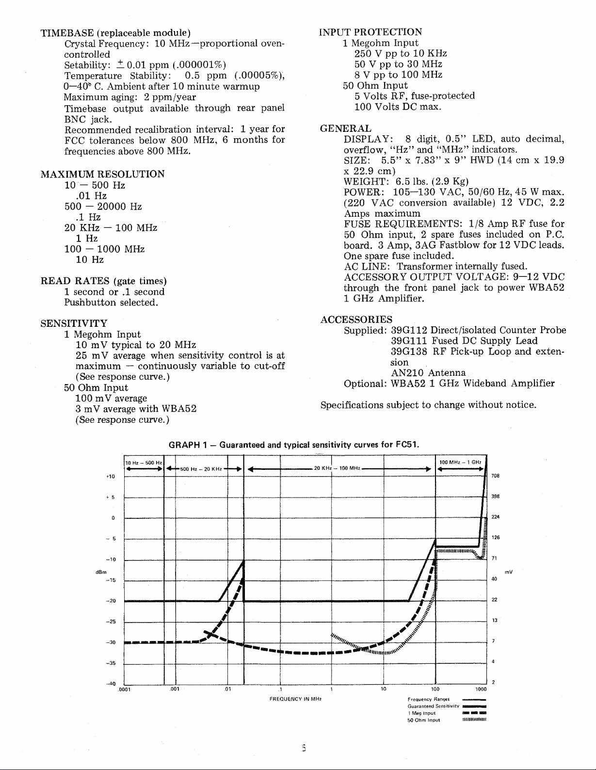
SEN SITI V I TY
1 Megohm Input
10 mV typical t o 20 MHz
25 m V average when sens it i v it y control is at
max i mu m — c on t inuousl y v a r ia ble to cut- off
(See respon s e curv e. )
50 O hm I npu t
100 mV average
3 mV average wi t h WBA52
(See res p onse curv e. )
ACCE S SORIES
Supplied: 39G112 Direct/i sola t ed C ounte r Prob e
39G11 1 Fused DC Supply Lead
39G1 38 RF Pick-up Loo p a nd exten
sion
AN 210 Antenna
Optio nal: WBA52 1 GHz Wideband Amp l i fier
Spec i ficat i o ns subje ct to change without no tice.
GRA P H 1 — Guaranteed and typical sensitivity curves f o r FC51.
F R E QU E N C Y IN MH z Frequency Ranges
Page 5

CONTROLS
LED read ou t , 8-digit wi th au to matic pla cemen t
of d e c i mal f o r all read in gs.
Overflo w ind i c a tor, which sho w s wh en reading
excee ds 99. 9999 99 or 999.99999 MHz.
Vinyl- c l a d steel case, provides full RF shielding
for stabl e readings.
INPU T SELECTOR BUTTON S
Crysta l check inp ut button for te sting crystals
ins erte d i nto soc ket (15).
1 Me g ohm inp ut but ton selects high sensitivity
input jack (14) for me a s urin g f req uenci es up to
100 MHz.
50 Ohm inp ut but ton sele cts high fr equency in
put ja ck (1 1) for p roper te rminati on of higher
inpu t signals. Op e ratin g r a nge 10 MHz—1 GHz,
H and l e/ t ilt stand for po rtable a pp l ication s or for
tilt ing un it on be n c h .
Powe r s w it ch, contro l s unit wh e n ope rate d fr o m
AC or DC inpu t s.
500 Hz—20 KHz range button provides in ter nal
Φ
re so l ution m ult i pli er t o p roduce .1 Hz resolut i on
with a 1 sec on d re a d rat e . Used only with 1 Meg
ohm i nput jack (14 ).
20 KHz —100 MHz ran ge button provides a d i re ct
Φ
(non -pre scal ed) in put for dir ect c ounting t o 1 00
MHz. Wo rk s wit h eit her in put ja c k (11 or 14).
100 MHz—1 GHz range button provides a 10: 1
φ
prescal ed input with automa tic decimal pla ce
me nt. Should be used o n ly with 50 O hm input
jac k (1 1 ).
MHz range li ght use d with aut om atic dec i mal for
direc t readout of frequen c y .
Hz range ligh t used with automat i c d ecimal for
φ
direc t readout of fre quen c y.
REAR PANEL
Timebas e output jac k provides a buf fere d output
/-if fJho 1Π MH7 rpfprAtirp ns Hllat nr fnv* nhw k infr
of the 10 MHz re f eren c e oscilla t o r f or c hecking
Θ
acc urac y wit h another f r e que ncy standard or for
cali brat i n g other less acc urat e coun t ers.
10 Volt accessory ja ck for po we rin g WBA52
1 GHz Wideban d Ampli f ier or o ther accessories.
Ground return is through shield of input jack .
50 Ohm i np ut jack prov id e s prope r termina tio n
for 50 Ohm coa x i a l cable to preven t doub le
co untin g d u e to r e f l ections. RF prot ecti on fuse
is loca ted inside un i t al ong with t wo spar e fuses.
REA D RAT E BUTTONS
.1 se c ond read rate provides appro ximate ly 1 0
readi n g s pe r second for fast updates whe n maxi
mum re s olu tio n is no t necessary.
1 seco n d read ra te provid es approx imately 1 read
ing per second fo r o n e e xt ra di git of resol utio n
and for more st a b l e readin g of “drift y” signals*
Sen s i t i vity adjus t cont rol op erates in conju nction
wi th 1 Megohm inp ut jack (14) to provid e variable
sen s i t i vity for meas u ring signals with n oi s e in
fo rm ati on .
1 Megohm i np ut jack pro v id e s high sensitivity
fo r dire ct signal c onn ections .
Cry stal check s ock et pr o v ides unive rsal sock e t
@ @ @00 © ΟΦΟ Θ Ο 9 φ φ θ
for t estin g crys tal s out of ci rc uit.
Antenna clips f or sto ri n g AN210 ant enn a.
Φ
Spare fuse clip for storing a spare 3 A m p fus e for
Φ
use in the DC supply leads.
AC input lin e cord .
DC i nput j ac k f or supplying 12 VDC ( negative
gro und ) for portable oper ation of counter.
Cord wr apper s for s to r in g AC line co r d a nd test
©
leads.
SUPPLI E D ACC ES S OR IE S
3 AN210 Adjust able Ante nna for picking up off-
the- a i r signals.
39G1 12 C oun te r Probe w ith direct / i solate swi t c h
for use when direct con nection is d es ir ed.
39G1 11 Fused DC Supply Leads fo r po wer i ng
FC51 fro m au to accessory j ack.
39 G138 RF Pick-up Loop for mak ing hig h fre
quenc y or hig h pow er frequ e ncy me asurem ents
whe n a direct c on nection is not des ire d.
OPTIONAL AC CESSORY
FRE QUE NCY RANGE BUT T O NS
10 Hz—5 00 Hz range but ton provide s inter nal
Φ
resolutio n mul ti p l ier to pr oduce .01 Hz resolu
tion wit h a 1 second read rate . Used only w it h
1 Meg ohm inp ut ja c k (14 ).
WBA52 1 GHz Wideband Amplifie r to increase
©
input sensi t i vity of e i t her 50 Ohm or 1 M ego hm
inputs for m e as u r i n g e x t r emel y small signals.
Power e d fro m 10 V o lt accessory jack (,9) on
FC51.
6
Page 6

ο ο σ ο
I. I ι ι
REAR VIEW
------
ACCESS OR IE S
Fig. 1—Location of controls ana features.
Page 7

O PE R AT IO N
INTRODUCTION
Befo r e using your FC51 for the firs t t i me , ta ke a few
mi nut es to read th rough the opera tio ns and app l ic a
tions sectio n of the manu a l c arefu l ly to acquai nt your
self wi t h the fe at u r e s of the FC51 . On c e you are f a m
iliar with the general op erat i ons, most t es ts can be per
fo rm ed with the info r ma t i on provide d on t he FC51’s
front panel .
POWER CONNECTIONS
AC OP ERATION: The FC51 is de s igned to b e oper
at ed f r o m 105 -130 VAC (50/60 Hz). If 210-230 VAC
opera tion is requir ed, the unit may be mo dif i ed (at
ad dit ional cost) by th e Sen core Service D epart ment ,
3200 Sencore Drive, S io u x Falls, SD 57 10 7.
To op erate t he FC51 from a st andard AC lin e:
1. C onn e ct the AC c ord to a 117 VAC (or 2 20
VAC fo r m odified u nits) ou tle t.
2. Turn the power s witch on.
3. The FC51 is i mm e diat e l y ready for frequency
me a sureme n ts. If very pre c i s e me asure me nts are
to be m a d e , the un i t sh ould be all owe d to oper
ate fo r at lea s t t en min utes to allow the tempe r
ature of the cr y s ta l oven to s ta bil iz e.
DC OP ERATION: T h e FC51 m ay be oper ated from
a 12 VDC power source cap a b le of d el iv ering 2. 2 Am p
eres. Po w e r is s u p p lied throu gh th e stand ar d ada pter
jack locate d at th e bottom of th e rear panel . A set of
fus ed DC sup ply leads is supplied with the FC 51 for
DC o per ation. Make sure the pr op er size fuse (see
FUS E RE P LACEMEN T b elow) is in the in-l in e fuse
hol der for prote cti on of yo ur FC51 duri ng DC o p er
ati on.
-----------------------CAUT ION-----------------------------
Observe proper p o la ri ti es (negat ive gr o und) when
connect i ng t he DC p o w e r source. No dama g e
will result if the polarity is reversed, but t he FC51
will not operate wit h a reversed pol a ri ty.
To oper ate the FC51 from 12 Volts DC:
1. Co nne ct the adapt er plug of the supplied
39G11 1 DC p ow er sup ply leads to the DC input
jac k on the back of the FC5 1.
2. Co nne ct t he sta nda rd a utomot i ve a c cesso r y
plug o f the supp l i e d power supply leads to the
sour c e of 1 2 VDC, observing p r oper polarity.
3. Turn th e po wer switc h on.
4. The FC51 is im medi ately ready for f requ ency
measure ments. If very precise me a s ure men t s are
to be m ade, th e un it sho u ld b e al low ed t o op erat e
for at le ast ten min u tes to allow the temperature
of the cry sta l o ve n to stab ilize .
_______
FU SE REPL ACEMENT
---------------------------
Always rep l ace the fuses wit h t he value sp ecif i e d.
Larger val u e fuses may cause in t ernal damage t o
the FC51 o r cause a fire haza r d and will void all
war r anti e s.
If th e FC51 s hould fail t o op era t e when c onn ected t o
a 12 V o lt DC p ow er sou r ce , check the, powe r su pply
fuse. If the fuse continues to b low each time it is r e
plac e d , refer to the service and mai ntenan c e secti on
of the m anual.
AC FUSE: The FC 51 does not require an AC fuse as
th e transformer uses a special in ternall y protected pri
mar y winding.
WARNING
--------------------------
Fig. 2—Connecting the 12 Volt DC supply lead. Be sure
to observe proper polarity (negative ground).
DC FUSE: Th e fu s e f or DC operation is loc ated i n t he
in-line fus e holde r in the 39G111 power supply leads.
Di sconnect the power su p p ly leads fro m t he DC sup
ply before r e movi n g the fuse. The fuse hold er is
open ed by pushing slightly ag ai n st th e t wo sections
of the fus e holder and tw istin g t he two sect ions in
opposi t e d i rec t i ons.
Replac e th e fuse with a 3 Amp Fastblow 3AG fuse
only.
50 OHM INP UT F U S E: The 50 Ohm input is prote ct
ed b y a special R F fuse loca ted inside th e b ot tom
cover o n t he inp ut PC board of t he FC51. F a i l ure of
th e FC51 to stab i li z e an d a lack of sensitiv ity th r ou gh
the 50 Ohm in put ind i c ates possi ble failure of the 50
Ohm inp ut fuse .
3
Page 8

Fig. 5—The fuse in the 39G111 DC supp ly lead is
changed by separating the two halves of the fuse holder.
The pr ocedu res for checking this fu se ar e as f o llows:
1. Connec t one end of the su p plied co nne ct or
cable wit h a BNC co nn ector on each e nd to the
10 MHz refe r ence output j ack located on the
ba ck of the FC 51 . C onne ct th e other e nd o f the
cable to t he 50 Ohm inp ut ja c k .
2. Depress the 50 OHM INPU T bu tton a nd the
20 KHz to 100 MHz F R E Q UENCY RANGE
button .
3. The coun ter should re gister 10.00000 MHz
1 count wh en the 1 SEC READ RATE button
is depre ssed. Failu r e to obt ain a c o r re c t reading
ind i c a t es f use failu r e . For fuse replace me nt in
structions, re fer to th e ma i ntenan c e section o f
thi s m anual.
TABLE 1 - BLOWN FUSE CONDITIONS
FUSE
DC Power
50 Ohm
input
TYPE
3 Amp 3AG Type
1/8 Amp iVlicro-
fuse
CONDITIONS
Unit will not turn on
when DC-operated.
loss of sensitivity at the
50 Ohm input. Unstable
readings in 20 KHz-
100 MHz and 100 MHz-
1 GHz frequency ranges.
Fig. 5—Access to the
50 Ohm inp u t fuse is
obtained by removing
the bo tt o m panel. Two
spare fuses are supplied
Be sure to disconne ct
the AC p o w e r cord be
fore removing the b o t
tom p a ne l
Fig. 4—Th e l O MH z ou tpu t (back panel) provides a con
venient signal source for testing the 50 Ohm in p u t fuse.
The cou nt er should read 10 MHz with good stability.
SIGNAL CONNECTION S
Several metho ds may be used for m e asuring fr equen
cies w i t h the FC 5 1 . In ma ny cases a dire ct conn ec tion
to th e circu it under test is desir e d . The 39G1 12 Fre
qu en cy Co un t er Probe, su pplied with the F C51, al
lows a dire ct or capa ci ti vel y iso lated co nnect i on. Othe r
te sti ng te chniques re quir e i ndi rec t or “l oose” coup
ling to p r event the cou nt er ’s in pu t circuits fro m dis
tu rb in g the circuit being m easured—the 39G1 38 R F
Pick -u p Loo p or the AN2 1 0 A nte nna ar e intend ed to
be used for th i s ap plica tion .
USING THE SUPPLIED
COUNTER PROBE
Th e supplied 39G112 Fr equen cy Cou nter Pr o be al
lows a direc t or capacitively is olate d inp ut. T he ch o i c e
o f th ese two inputs is made with a miniat ure slide
switch built into the probe. The Freq ue ncy Counte r
Probe may be used w it h the 1 MEG INPUT or th e
50 OHM IN PU T.
Fig. 6—S upplie d 39G112 Counter Probe is equ ipped
with a switch to select direct or isolated connections.
9
Page 9

The follo w i ng are guidelines as to whe n to use each
opti on availab le w ith t he 39 G1 12 Freq ue ncy Cou nter
Probe:
1 MEG IN P U T, DIREC T CO NN E C TION
Gene r a lly, this connection is us e d for m eas uri ng fr e
quen cies that require a direct conn ectio n. T he 1 Meg
ohm loa ding of t he FC51 in put will n ot affe ct most
circ u i t s is olat e d from an oscilla t or by at least o ne am
plif i e r (buffer ) stage. This co nnection of fer s t he high
est co unter sensiti vit y for mea s urin g lo w -le v e l signals.
At fre q uencies above 10 MHz, the positioning of the
gro und connection ma y a ffect the stabili ty of th e
reading . If an unstable readi n g is obt ained at the se
higher frequencies , it can g e n e rally b e made more
stabl e by ad j u s t in g the i nput sens it i v it y contro l and /or
movi n g t he gro u n d conne ctions as close as possi b le to
the t est point being m easure d .
1 MEG INPUT, ISOLAT ED CON N E CTION
The i s ola t ed switch p osition of the 39 G112 Cou n t er
Pro b e insert s a 33 p F iso l ation capacitor in series with
the test lead. This series cap aci t anc e reduce s the cap
aci t anc e for me d by the cable run nin g fr om the counter
prob e to t he c ounte r input. This iso l ation allo w s con
nectin g the probe to many o s c il lators t hat b ecom e in
ope r ative when a direct c onn ection is made. As with
the direct conn ection, the position of the ground co n
ne cti on ma y aff ec t the sta bilit y of higher frequ ency
me asu r em ent s .
50 OHM INP UT , DIR ECT CONN ECT ION
The 50 OHM. INPU T pr ev en ts refle cted signals on the
50 Ohm cab l e of the count er pro be. This termin atio n
is esp ec ia ll y i mportant when measur in g signals w it h
fas t transition s such as square waves or logic pulses
fro m s ome digita l circuits. Th e 50 Ohm t er mination
prev e nts cable rin gi n g which may occu r d ue to the
fast rise-time of these signals.
NOTE: The 50 Ohm input may load the o ut p ut of
some logic ICs. See “Special Digital Applic at ion s” for
techniques tha t prevent this circuit loading.
50 OHM I NPUT , IS O L A T E D CONNE CT ION
This opti on is gen er a ll y not used because it offer s no
real advant age over the above connectio n. The input
to the 50 Oh m i nput is AC-coupled to prevent DC
circu i t load ing.
THE 39G138 RF PICK-UP LOOP
The r e are many times when a di rec t count er c onn ec
tion is not desired. Many osci l l a t ors used i n co mmu n
icat i o ns equipm ent can no t be me asur ed with a p r obe
connec ted -eve n with the is ola t ion capacitor in-c ir cuit.
The pr obe’s capa c it a n c e may cause t he fre qu en cy of
the oscillator t o change, or cause t he os cill ator to sto p
runni ng, as the lead cap acit ance is plac ed in parallel
wi t h the o scillator circuit. Trans mit t ers may h ave v o l t
ages exce e ding the protecti on rating of t he 1 Meg in
put a n d the 50 Ohm input. Fo r these applications,
an indu ctive pickup loop ma y be us ed to “sniff ” th e
frequenc y witho ut a direct connecti on elimin a t i ng in-
Fig. 7—The 39G138 pic ku p loop allows signals to be
pic ke d up withou t a direct connection. The supplied
exte nsio n cable and “barrel'’ conn ector provide co m
plete versatility in making connections.
ter fer enc e with th e measure d circ uit an d , at the same
time, pro v i ding inpu t p rot ecti on to the FC51 input
circuit s .
The 39G 138 ma57 be used with eith e r t he 50 Ohm or
1 Megohm inpu t depen ding on the specific a ppl ication.
The 1 Megoh m input provides better sen sitivity at
lower frequenc y ranges (generally 1—80 MHz). Th e
50 O h m input, on th e o t he r h and , provide s a termi n
ati on whi c h will make the 39 G13 8 mor e ef f ective at
higher fr e que nci es. The 50 Ohm input will also ke ep
the amoun t of signal app lied t o th e counter in pu t
lower , which mak e s it better suit ed for use in high
po wer a ppl ica tio ns (over 50 Watts R F).
The 39 G138 is supplied in t hree sections: 1. ) The
pick -u p l oop itse l f w ith a shor t coaxial cable s tub,
2.) An ex tension cabl e with a BNC conne ctor at b oth
ends, and 3. ) A BNC to BNC “barrel” t o allow the
two sections to be con nect ed toge ther. This allows
many option s for pickin g up signals in differ ent lo
cation s .
When the 39G138 Pickup Loop is used with the F C51,
the ex tension cable provides a c onvenie nt leng t h for
most signal tracing. When the 39G138 is use d with
th e optional WBA52 1 GHz Wi de b an d A mpli f i e r , t he
39G13 8 will generall y be used w itho ut the exte nsi on.
This allows the WBA52 to be used as a “handle” for
hold i n g onto th e pi ckup loo p du r ing operati on . The
adva n t a g e to this is th at th e a mou nt of ca b l e leng t h is
kept t o a m inim um a t th e in pu t to the high se n s it i v it y
amp li f i e r to pr event noise picku p .
Ad diti ona l uses o f t he exten s ion cable will be foun d
in testing with the su pp lied an tenna (see “Using the
Page 10

1. Used with 39G138 pick up loop.
2. Used with 39G 112 cou nt er probe.
} © 3 3
.
....
χ
□ ι μ i
» ■> o a cL· eo
3. Used for testing generators with 100 m V out put
Connect
to
10 MHz
output
at back
5. Used with A N 2 1 0 ante nna.
Generator
@
4. Used for testing
50 O hm fuse.
&
A
Fig. 8—Uses o f supplied cables.
AN2 10 An te nna”) and for checking the 50 Oh m inp ut
fuse (see “Fuse Replacement”).
To use t he 39G138 Pick-up Lo o p:
1. Connec t the 39G1 3 8 to th e 1 Meg or 50 Oh m
inpu t of the FC51 , using the ex ten s ion cable.
2. S e lect the desired INPUT, READ RAT E, and
FR EQ UENCY RANGE butto ns .
USING THE 39G138
WITH TRANSMITTERS
OVER 100 WATTS
The 39G138 may be used to measur e t he ou tput fr e
qu ency of extrem ely high-po w e r tr ans mit ters . How
ever, ca re s ho uld be us ed to pre vent pos sib le overload
dam a g e to th e FC51 or a shock ha z ard to th e oper
ator. Always use the 50 Ohm input for t hes e high
pow er a ppl i c atio ns. T he input prote ction fus e will
pro vide addit iona l in put protect ion when making these
me asu r ement s .
When me a suring co mmer c i a l AM, FM, or T V tran s
mitter outputs, the RF pickup loop should be placed
as far fr om t he high-p o wer output circuits as pos si b le.
Begin with the lo op several inc h es from t he signal to
be mea s ured , and then move the lo op t owa rds the ou t
put stage u ntil a sta ble cou nt is registe r ed . If the tran s
mitter is pr ovided with a sampler c i rcu i t which samples
the RF signal an d provides a low-level o ut put, thi s
con ne cti on s hould be used for freq uen cy co unter co n
nections .
USING THE AN210 ANTENNA
It is of ten de sira b le to be able to ma k e fre quency tes ts
with out the need of removing any of t he covers of a
tran smitter, o r to te st th e transmi tte r fre que ncy wit h
o ut removi ng i t f rom service. Exa mples of th is typ e
o f measurem ent are: 1.) Testing the output fr equency
of a walk i e - talkie , 2.) Testing a repe ate r transmit te r
wh i c h ca nno t be removed from service withou t cau s
ing dow n-ti me whi c h w ou ld put the re peate r user s out
of radio con ta ct , 3.) Te st ing a com merc i a l AM, FM,
or TV st ati on wh i ch may o t herw i se require that the
tr ansmitter be turned off, 4.) Measuring t he frequency
of a mobile tr ans mit te r by simply driving up next t o
the trans mit ter and tes t i ng the frequ e ncy without the
nee d of pull ing an otherw ise good transmitter f rom
service. Eac h o f t hes e a p plica t io ns is best s erv ed wit h
the use of t he AN210 Fre quen c y Cou nter An t enna.
3. Place the pic k up lo op nea r a ca pa citor or coi l
in the circui t to be tested. If an unsta ble cou nt
is obtaine d, re-po s it io n the pick up loo p as n ec
essary to stabilize the coun t. If no count is ob
ta i ne d, tur n t he pick u p loo p over (which reverses
the polari ty of the picku p loop’s coil) or sel ect a
diff er ent c ompone nt in the c i rcuit.
4. Th e pickup lo op will work be s t when placed
n ext to or around a coil. However , the h igh sen
sit i vity of the FC51 will also allow signal p i ckup
from capac i t ors, t r a nsistors, or cry s tals i n most
circ uits .
The pick up loop may be used to trace a signal t hro ugh
var i ous stages o f a c i rcuit b y pla ci ng t he coil n ear each
stage. Genera l l y, it is best to start wit h the signal
source (osc i l lator) and work tow ard s t he out pu t stages
wh e n signal tr a c ing.
Fig. 9—The AN 21 0 antenna allows measurements of
off-the-air signals for such applications as testing walkie-
talkies. The length o f the AN21 0 should be adjusted
for best sensiti vity.
11
Page 11

The AN210 is adjustable so that it can be tuned to
various fre q u encie s for ma xim um sen sitivity . The
AN 210 can be used wit h eit her the 50 Oh m or the
1 Megohm input, but is g en erally used wi th the 50
Ohm i nput fo r mea s u r emen t s above 90 MHz. Th e
accomp any ing graph shows the op timu m length for
each freq uen cy to be measur ed. Begin by setti ng the
len gth o f the AN21 0 to t he l engt h sho wn in th e graph
fo r thes e high e r freq u e n c i e s . Fre que ncie s belo w 90
MHz should be measu re d with the anten na fully ex
ten de d. If a stab le c ou nt belo w 90 MHz is not possible
wi th the ant enna con nected to the 50 Ohm inp ut,
mov e it to the 1 Megohm in put and adjust th e ant enna
fo r the most sta b l e reading.
Th e bes t sensiti v ity is possible wit h t he ante nna of the
tr ansmit te r as close as pos si bl e to the AN2 1 0. A 2
Wat t walkie- tal k ie , for example, can u s ually be meas
ur ed for a distance up to 20 feet away from the c ount
er ant enna. Addit i onal s e n s it i v it y provi ded b y the
opti onal WBA52 1 GHz Wideban d Am plifi er allows
the use o f the AN210 for special applic ations req uir
ing greater distan c e s such as po r tab l e test i ng o f m o bile
tra nsmi tte rs.
It is s ome t i mes desirable to ha ve the a nte nna some
dis t ance f rom the counte r . This is especia ll y tr ue
wh e n used in m o b i le appl i c a tion s . Simply us e the ex
tensi on cable and barre l suppl i ed wit h th e 39G13 8
Pi cku p Loop as an ant enna ex t ens i on.
To use the AN 210 An t enn a with th e FC51:
1. L o cat e t he freque n cy coun t er near the sou r ce
of RF signals. T h e op tim um dist a nce will depend
on the specific fre que ncy being m e a su r e d and
th e o utput pow er o f th e transmi tter.
2. Co nnect the antenna to the desired in put us
ing the guid elines co ver ed above.
3. Select the proper INPUT, REA D RATE, a nd
FREQ UE NCY R A N G E but t on s .
4. Adj ust th e antenna length for t he mos t stab l e
readi n g s . Ref er to grap h II for t he proper anten
na leng t h for fre q u e n c i e s above 9 0 MHz. If the
read i n g is no t stabl e , read j ust the an ten na length
or re-positi on t he t ran sm i tter.
5. Re ad the resu l ting frequency .
NOTE: High levels of modulation (either A M or FM)
may cause so me instability in the readings. If such in
stabilities are present, the modulation should be re
duced or removed until the frequen cy measurement
is com ple te . See the ‘'Applications'’ section of this
manual for details on measuring modulated frequencies
I f yo u need to measure frequencies at greater distances,
the WBA5 2 should be used. See “Using the WB A 5 2 ”
section of this manual for details.
GRA P H 2 — Proper antenna length for best sensitivity.
TO MHz
100 MHz 200 400 600 8 00 1 GHz
frequency
Page 12

SELECTING PROPER INPUT
The FC51 of f e r s t hree counter i nputs: A 50 Ohm i n
put, a 1 Mego hm adjust ab le sensit i vity inpu t, and a
cry stal check input. The follo w i n g instruc tion s cover
each inpu t :
5 0 OHM INPUT
-------------------------
The maximu m inp ut th e 50 Ohm input c a n safe
ly dis s ipate is .5 Watts. High er inp ut pow er will
cause th e 50 OHM INPUT protect io n fuse to
blow. The m a ximum DC volta g e that can s afe ly
be connecte d to th e 50 Oh m i nput is 100 Volts.
Th e 50 OHM INPUT is design ed to be used with eithe r
th e 39G 138 RF pic k u p loop or the AN210 adj ustable
anten na for me as ur in g signals with i n t he 10 MHz to
1 GHz range. Fo r details on using e ither the 39 G138
PICKUP LO O P or the A N210 ANTEN NA, refer to th e
“S IGNAL CON N ECTIO N” s ecti on of t his ma nual .
WARNING
------------------------------
Β*?ασ§0θθ-
S E N C O R E " 16H* FBSOUeriCY CQU iitKn
------- /" ftE ftD R ATE —ι .
----
FREQUENCY RAn tCT
1 MEG INPUT AND SENSITIVITY
ADJ UST
I---------------------------WARN I N G
I The 1 Meg lo a d is protecte d ag ai nst ove r load, bu t
1 t he amount of protection changes w it h in put fre-
I q uency. Do not a p p l y m ore input signal tha n
I lis t e d in the tab le below or pos sible damage to
1
I the in put preampl i f ier ma y res u l t . Such o verload
is not covered by Senc ore’s 90-D ay Warran t y or
100% M ade Rig ht Li f e ti me Guarantee .
TABLE II - OVER LOAD PROTECTION
FREQUENCY RANGE
10 Hz - 10 KHz
10 KHz - 30 MHz
30 MHz -10 0
The max i mum DC bias signal th at may be ap plied is
25 0 Volts.
The 1 MEG I N PUT is designed to ac cept signals with
in th e 10 Hz to 10 0 MHz r ange. The connection to
thi s input is usually made with the 3 9 G112 Counte r
Prob e . A slide switch , on the pr o be, selects eithe r a
direct or an is ola t ed input . F or details c onc erni n g the
use of th i s probe , ref er to the “USING SU P P L IED
PROBE” secti on under “SIGNAL CONNE CTIO NS”.
-------------------------------
MAXI MU M INPUT VO L TA GE
250 VP-P
50 VP-P
8 VP-P (3V RMS)
Fig. 10—The 50 Ohm input is generally used with the
39G 138 R F pick up loop or AN2 1 0 antenna fo r meas
uring high frequencies.
To use the 50 Ohm inp ut:
1. Connect t he desired signal t o the 50 Ohm in
p ut jack. See “Signal Connection s” f or det a i l s.
2. Depre ss th e 50 OHM INPUT button on the
fr ont pane l .
3. Sele ct the desired READ RATE and FRE
QUE N C Y RANG E buttons as descr i bed in the
foll o win g sect io ns.
4. Rea d th e resultin g fre que ncy on th e digital
re ad out.
s e n c o r e ish > rn e a u E N ev c o u n t » »
inputs—
----- · -wEfto η η τ ζ facQurracv q a
Fig. 11—The 1 Megohm input is used with the supplied
39G1 12 counter prob e or 39G138 RF pickup loop for
measuring frequencies from 10 Hz through 100 MHz.
Com plex waveforms oft e n p resent d iffic ulty in mea s
ur ement. T he fr equ e ncy co un ter will res po nd to all
of th e f r equen cie s and may have an unstab l e re a ding.
The Sensitiv it y Ad j ustme nt reduces the sens i t i v i t y of
the 1 MEG INPUT so th at it r e s p o n d s on ly to the
large s t amplitude signal.
13
Page 13

To use the 1 Meg i nput and the sens it i v ity ad j ustmen t :
To perf orm the exte r nal CRYSTAL CHECK:
1. Conn e ct th e desired signal to the 1 MEG IN
PUT jack. See “SIGNAL CO NNE CTI ONS ” f or
details .
2. Set t he SEN SIT IV IT Y ADJUST MENT to m ax
imu m. Note: This is its “normal” positi on for
most mea s u rement s .
3. Depress t he 1 MEG IN PUT butt on. Se lect the
desi r ed REA D RATE and FREQUENCY RANGE
but to ns as desc ribed in the follo win g sections.
4. R e a d the resulting fre quency on t he Digital
Readout. An u nstab l e or incorrect r eado ut may
be corrected as fol lo ws:,
A. Graduall y reduce th e sensi tivity wit h the
sensiti v ity adjus t me nt control u ntil the digits
loc k in.
B. Read t he res u lt ing fre quenc y.
CRYSTAL CHECK
The CRYS T A L CHECK functi on all o w s any crystal
wi t h a fun damenta l fr equ enc y of 1—20 MHz to be in
se r ted into the f ront panel universal cry sta l soc ket to
che ck for cryst a l a cti v it y . The cr yst al will be made to
resonate at its f undamental operating frequency.
NOTE : Most crystals used in co mm unic ati ons equip
me nt are designed to operate on an overton e rather
than their fundament al frequency. For exam ple, an
oscillator operating at 2 7.0 00 MHz will use a third
overtone crystal with a fundam en ta l fre quen cy of
.9.000 MHz. In practice, there are few, if any, crystals
with a fundamen tal frequency of over 20 MHz. The
exact operating frequency o f the crystal depends on
the circuit o f which it is part. Measurement of the
exac t operating frequency of the crystal is only pos
sible by measuring the o u tp u t of the circuit in which
it is operating.
1. In s ert the cry s t a l to be tested in t o the front
panel s oc ket mar ke d CRY ST AL CHECK.
2. Sel ect eith er the .IS or I S REA D RATE but
to n.
3. Depress the 20 KHz—100 MHz frequen cy range
but to n.
4. Depress the CRYSTAL CHECK butto n.
5. Read th e fu nda me nta l crys t al fr equen cy on
the digital r ea dout.
Defec t iv e or i noper ative crys ta ls will be indic ate d by
an in termittent or ze r o r ead out .
f ι n j ι i_ ι ι
I m|; I / ·* <( im i I MHr·
S E N C O R E .. 1BHi FREQUENCY COUNTER
-iwpirra —
• · ? MEi iV f
• ■ '"I1111
Fig. 12~~The crystal check reads appr oximate ly the
fundam ent al frequency of the crystal inserted into the
test socket. This fifth overtone crystal normally oper
ates at 55. 16 0 MHz.
-READ BATE-. .
Λ I I I I
am sinsirrmi i v h k
------
FREQUENCY HANG*
-Γ ϊ p·*
SELECTING FREQUEN CY RANG E
The fou r f req uen cy ran ge button s of the FC 51 offer
th ree differen t method s of i nput signal con ditioning
wh ich ar e aut om atic ally selecte d by the FREQUENCY
RANGE b utto ns. Audi o freq uencies (10 Hz—20 KHz)
are automa t ically routed thro ugh a “ reso l ution m u l
ti pl ier” cir cu i t which allows an incre ased nu mbe r of
digits of disp l ay for added a ccu rac y in mea s urin g these
low fre quenci es. The r e sult is a resol ution of .01 Hz
throu gh 500 Hz, and .1 Hz f r om 500-20 KHz. The
deci mal pla ce is a utomatically place d when the reso
lution mu ltiplier circu it s are act i vated.
The res oluti on mu l t i p lier provides addi t iona l filtering
of lo w frequency signals to pr event i nte rference fro m
noise informatio n. This filte ring actio n, co mb i ned
ι r
lOIMQOtiz 5 9flHz 2QKHz 20KM0MHz 100MHz 1GHz
Fig. 13—The fo ur frequency range b uttons au tom ati c
ally pos ition the decimal for direct readouts. No tice
the ranges are listed above each button.
14
F RE Q U E NC Y RAN GE-
1MEG Π
IOHz- iOOMHz
CRYSTAL CHECK
Page 14

wit h the adjustab l e sensi tivit y control asso c ia t e d with
th e 1 Megoh m inp ut, allows the meas ure me nt of au dio
signals that are generally not po ssi bl e to measur e with
oth er high-s en s it ivit y cou n t e rs . Seeth e “Appli catio ns ”
section of this manu al for details abou t the commo n
causes of noi sy signals. The 1 M egohm i nput shou ld
be u s ed fo r all a udio meas u rement s .
Fre quenc ies be t wee n 20 KHz and 100 MHz a r e fed
di r ect ly into t h e count i ng s e c ti on of the F C 5 1 throu gh
a sp ec ia l pre-a mplifi e r . This allows me asurements wit h
re solution d own to 1 Hz for th is frequency range.
The 20 KHz-100 MHz F REQU E N CY RANG E but
ton c an be used with e i th er t he 50 O hm or th e 1 Meg
ohm input. This fr e quenc y ran ge button is also us e d
wi t h the CRYSTA L CHECK function .
move deci mal places for any o f the fre quenc y ranges
covered by the FC5 1 .
It s hou ld be noted tha t t her e is some overlap b etween
the f r equency ranges that is n ot noted on the front
panel. For exa mp le, the 20 KHz—-100 MHz range is
generally usable as low as 1 KHz, and as high as 11 0
MHz. The 1 KHz-—20 KHz por tion o f th is range will
usually not be used, how e v e r , b ec a u se the next lo wer
range (50 0 Hz-~20 KHz) offers on e mo r e digit o f r eso
lut i on, which prov i des more accu r a t e low - f r e quen c y
me a s uremen t s . The follow i n g tab le lists typ i c a l ove r
laps so t hat you know th e ap pro ximat e counting ra n ge
of e ach F REQUE NCY R A N G E bu tton.
The fina l b utt on rout es th e signal throug h an in ternal
10 :1 presc a ler f or measu ri ng frequ e ncies betwee n
10 0 MHz and 1 GHz. This ran ge butto n is o nly used
wit h the 50 Ohm input since the capacitive loadin g of
th e 1 Meg o hm input w o ul d make it less u sefu l above
100 MHz. Signals applied t o th e 1 Megohm input j ack
will not m easure if the 100 MHz—-1 GHz ra n g e button
is sel ect ed. The decimal place in the digital r eadou t
is automa t icall y po sitioned when th e interna l prescal er
is switc hed in , whi ch eliminates the n eed to me ntally
nano 3 o . a
j ι t.iy 1 i'
" I' s a s
Frequencies between 10 Hz and Frequencies between 500 Hz and
500 Hz are multiplied by 1 00. 20 KHz are mu ltip lie d by 10.
T ABLE US
RANGE
SELECTED
10 Hz -5 0 0 Hz
500 Hz-20 KHz
20 K Hz-1 0 0 MHz
100 MHz-1 GHz
ΒΗΏ:D S DO 13.
- TY PIC AL FREQUENCY RANGES
USABLE
RANGE USED
8.5 Hz - 550 Hz
450 H z -21 KHz
1 KHz -1 10 MHz
50 IMiHz -1.1 GHz
INPUT
1 Megohm
1 Megohm
Either
50 Ohm
.
r 113
Frequencies between 20 K Hz and
100 MHz are read direct.
ιτ τ γ ίί
Frequencies bet ween 100 MHz and
1 GHz are divided (prescaled) by 10.
Fig. 14—Al l frequencies are read direct with m ax im um resolution when the
proper range butto n is pressed.
Π Q Li u η n c . 11
■mmI I I · I W l-m l - J I Mitt
1
G Hz FRE Q UE N CY COU NT ER
-IN P U T S
Fig. 15—The “o ve r ” light is like a number “I ” in fr on t of the reading when
frequencies over 1 GHz are read. Here we see a frequency of 1094 MHz or
1.094 GHz.
-R E A D R A T E -
- FRE QUENCY RANGE
Page 15

SELEC TING RE A D RATE
The FC 51 allows the ch o i c e o f two different re ad rates.
In general, the .1 s e c o nd READ RATE but ton is used
when a fast update ti me is de s ir e d . The use of the .1
sec o nd READ RAT E , how e v e r, resul t s in one less digit
of reso l ution for each fre que ncy range com pared to
the 1 secon d READ RATE. Th e .1 second read r a te
will also show a more rap id chan g e in t he r e ad in g if
the test ed signal is c h an gi n g in f requency. An example
of such a changing fre que ncy is one p r ov i ded by an
LC t ank (non-cr y s tal) oscil l a t or circ uit.
The 1 second READ RATE offer s an extra digit of
resolut i on. Since the inp ut frequen cy is cou nted f or
a longer pe r iod of time , frequ enc y changes (s u c h as in
th e LC tan k m enti oned above) will be avera g e d which
of ten pr o v id e s a mor e sta ble count . This frequenc y
averaging often ma kes t he 1 seco nd READ RATE eas
ier to use.
The FC51 offers 8 di ffe rent opt ions of resolu t i on,
depen din g on w hich F R E Q UENCY RANGE and which
READ RATE o ptions ar e us ed. Ta b le IV li sts th e di f
fe rent resolu tio n options that ar e av ai la bl e.
T ABLE IV - FC51 RESOLUTION OPTIONS
1 See
.01 Hz
.1 Hz
READ RAT E
.1 Sec
.1 Hz
1 Hz
100 Hz
FREQUENCY RANGE
10 H z- 50 0 Hz
500 H z -2 0 KHz
20 KHz - 10 0 MHz 1 Hz 10 Hz
100 MHz -1 GHz 10 Hz
/ π “/ π π ~ r r r "7
/ u. ι u U d b c
S^G l Q Re .· · 1 Q H z FR E D U
----------
INPUTS
------
-----
■ ■<? fill * r ilYSTM ! UC I l !l*J.^|!|i> Λ Jli MI· ll*V|i -V
. ,-REAO RATE—' -------
* -- .1.,........ I-1
'NtHl-tSHj AOJBST <GH; lOQMHv
i p#·.i
1 Second R e ad Rate
n i η 7 n n z\ t
id ι l-L J L I U L· D. mr
S E M C O R E ,' . 10HV FREOUEWC^ C O U iii^
Hft l P UTS-'
------
··;::····".···.·.! .Sks···. ■ I Sfi » T O iSKH/ MKto \m
- v rREAD BATE - n ,
FREQUENCY RAWGC
-----
F REQUE NCY RANGE
MO DEL fC/.:
IT T
iCMHclGtfr AQ,RJi!T
MODEL FC51
.1 Se cond Read R ate
Fig. 16—The 1 Second Read Rate provides one extra
digit o f readout and the .1 Second Read Rate provides
faster update s.
INCREASING INPUT SENSITIVITY WITH (OPTIONAL) WBA52
The inp ut s ensitivity of t he FCol has been designed
to provide compl ete troubles ho oti ng cap abilities in al
m ost all appl i cations re q uiring a frequenc y c ounter.
The 50 Ohm inpu t, f or example, h as sufficie nt sen
sitiv it y to allow the use of the supp l i ed 39 G13 8 p ick
up loop to trace signals from os cilla tors, frequen c y
multiplier stages, and output stages o f a t ran sm i t ter .
Ad d ed sensitiv ity can actua l l y be a detri ment in some
of th ese appl i cations, as addi t i onal sen sitivity also in
creases the chanc es of p ic k in g u p n ois e signals wh ich
can lead t o erratic coun t i ng.
There are, howe v e r , a few app l i cat i ons that re q u ir e
ad dit i on al s e n siti v ity. Ex am pl es would i ncl ude me as
uring t he output of a signal generato r that has li m it e d
output, using the AN 210 Ante nna fo r pic king up sig
nals at great e r distance s, or using the 39G13 8 Pic ku p
Lo op for tr a cing signals that are e xt remel y low in a m
pli t ude. T h e optional WBA52 p r ovid e s a pp roxima t e
ly 30 dB (see Graph III for t ypic al gain) of gain fr o m
1 MHz thro ugh 1 GHz for thes e spec ial applica t ions.
The WBA52 simply co nnects to ei th er of the FC51
inpu t ja ck s and receives p o wer fr om the 10 V DC Ac
cessory Output Jack on the FC51 fro nt panel . T he
WBA52 can be used when the FC51 is powered from
eit her the AC li ne or fro m 12 VDC.
~ * > >.
Fig. 17—The WBA provides extra sensitivity fo r special
low-level signal tracing applications. The W BA 52 ii
powered by the FC51 DC ou tp ut jack.
16
Page 16

0.1 1 10 100 IK 10K
FREQUENCY IN MHz
Addi tio nal app l i cati o ns of the WBA52 inclu de boost
ing signal levels from the out put o f an EF generat or
fo r uses oth er tha n countin g wit h the FC51 . These
ap plicat i ons are covered in the WBA52 i ns tructi on
manual.
Th e in put of the WBA52 is te rminated in a well-
m atch ed 5 0 Ohm load so it will opera te pr op erl y
thro ughout its enti r e freq uen c y range. Several signd
input op tions are available, in cludin g :
1. The AN21 0 An ten na may be conne cted direct
ly to th e WBA 52 input for of f -the - air monitor
ing wi t h high sensiti vity .
2. The AN210 Antenn a may be connec ted
throu gh the extens i on cable supplied w ith t he
39G 13 8 pickup loo p for similar mea s urement s,
b ut w i th t he antenna separate f rom the ampli f i e r .
This is especially hand y w h en us in g t he WBA52
and FC 5 1 in portable applic ation s .
3. A receive r antenn a may be moun ted on a car
or truck and conne cted to the WBA52 ( thro ugh
appropriate ada pte r s) to allow you t o drive up
n ext to a transmi tter and m e a s u r e its output.
4. T he sho rt 39G1 38 Pickup L oop may be con
nected di rec t ly to the WBA52 for signal tracing .
The short l oo p offers th e advan ta ge of having a
minim um amount of cabl e to keep noise pic kup
to a m i nimum.
5. The 39G138 Pickup Loo p m a y be used with
the e xte nsi on cable sup plied with the FC51 fo r
getting the loop in to mor e diff i cult to reach
locati ons .
6. Th e o ut put of a generator may be me a s u red
wit h a dire ct c onnection fro m th e genera t or out
put to the WBA52 input . T he BNC/BNC ext en
sion cable suppli ed wit h the FC51 is used wit h
gene r a tors with a BNC out put jack, or use a p
pr opria te adap ter cables for generato r s with o t her
o utp ut connect ors .
You m ay find that so me mea surem e nts using the pic k
up loop result in noi se pi ckup b ec a u se o f the e xtreme
ly high sensiti v it y provid ed by the WBA52. This can
usuall y b e cor recte d by moving th e picku p loop slig ht
ly t o provid e a grea ter amoun t o f signal and less noise.
Signals below 100 MHz may be mea su r e d w it h the
WBA52 conn ect ed to the 1 Megohm inp ut. This al
lows the sensit i v it y con trol t o be us ed to ad just fo r
optimum s ensit i v it y in nois y signal con ditions.
17
Page 17

APPLICATIO NS
Fo r mos t ap p l ic ations, t he techni cia n me r ely connect s
th e test leads to the frequency so urc e, selects t he
pr oper INPUT, FRE QUEN CY R ANG E and READ
RATE butto ns , a n d re ad s the fre qu ency on the digital
re adout . Certain t ypes of signals a r e a lit tle more dif
ficult to measure because of low amplitudes or in ter
fering signals. This s ection will explai n why t he FC51
may give er r a t ic readings on s o me signals, and wha t
the technic ian sh o u ld d o to pr oduce a stab le read in g.
Erra t ic readings generally come from t wo ty pes of
signals. The fir s t is an AM or FM mod ulated signal.
A mo du lated signal can of ten be cou nt ed w itho ut an y
special proce d u r es but i f th e mod ulatio n level is too
high erra t i c counting ma y r e sult. The second cause of
erra t i c co unt i ng is due t o extraneous signals riding on
the desired signal. This c onditi on is most prevalen t in
low er fr e que ncy signals, aud i o th ro ugh a few Mega-
Hertz . Th e FC51 provides buil t-in f eat ure s that allow
m os t of t h e s e signals to be counted. We will discuss
th e causes of the erratic counting and th e p ro per meth
ods of stabiliz ing t he r e a ding in this secti o n of the
ma n ual.
AM MODULATED SIGN ALS
In many cases, the F C 5 1 will p roper l y coun t the c a r
rier of an AM-mod ula te d signal. The exc ep tion is wh en
the mo du lat ion level is very high. High level AM mod
ulati on ma y result in an erra tic count or a freque n cy
reading that is lower t han expe cte d. The reason is that
th e signal level of an AM signal is co nstan tly varying.
Durin g periods of hig h mod ul ati on , a portion of t he
signal Mis close to zero. The FC5 1 will then count
on ly that por tion of th e signal that is la r g er than the
sens i t i vity ratin g o f t he in put circuit s b ut will fail to
count tho se other portions of the signal t ha t are low-
ampl itu de.
The easi e st way to prevent co unti ng err o r s when mea*
uring th e carrie r f requency of an AM transmi tter is t<
“dead -k ey ” th e trans mi t ter or t ran sm it withou t moc
ulation. This can generally be don e witho ut se ri o u s !
aff ecti ng the transm itted signal as t he en tire count cai
be made in two second s or less. If it is not practice
to rem ove the modula t i on for this amount of tim
(as in the case of a co mmerci al AM b r oa dcast s t a tion
the counting e rro r can be min imized by inc r easing th
amount of signal t hat is fed to the count er. You mus
keep th e prot ecti on limits of the coun ter i n mi n d, o
course, when increasing the inp ut signal. Increas in
the input signal will increase the am ount of signal thi
is present du r i ng mod ulat i on peaks wh ich will kee]
the counting error t o a minimum. It will al so help t<
use the 1 seco nd read rate instead of the .1 seconi
read rate, beca u s e the 1 se c o nd m o de will ave ra ge t h
num ber of missed c o unts ove r a mu ch longer perio<
of time t o keep a more s ta bl e reading on the digits
display.
FM MODULATED SIGNALS
An FM signal may cause e r r atic counting because th·
frequen cy o f the' signal is c ons t a ntly cha n g i n g . A
with AM signals, th e best way t o insure a s t able cou n
is to rem ove th e mod ula t ion durin g the perio d of ti m
that the cou nt is taken. If this is not p r a ctica l , be sur
to use the 1 second r e a d r ate. This will average th
amou nt of time t hat the f r equency is h i gh er than th
carri e r wi th the time th at the fr e que ncy is lower thai
the ca r r i er and provides a frequency rea d in g that is ver
close to the a ctu al carrie r fr equency.
Fig. 21—The amplitude o f an AM modula ted signal
may drop below the sensitivity p o i n t of the FC51,
causing part of the signal to be missing by the counting
stages.
+ 50 KH z -5 0 K H z OF F
CEN T E R FR E QU E NC Y
Fig, 22—The frequency of an FM mod ula ted signal u
constantly changing, causing erratic co un tin g due tc
the averaging of dif ferent frequencies.
NOISY SIGNALS
Erratic c ounting of low f r equ ency signals fall i nto four
general cat ego r i e s: 1.) An aud i o signal with cross-over
or h arm oni c dis t ort i on, 2.) A signal w it h an unwa nted
Page 18

secon d freq uen cy (like ripple) su p er-impo s ed on the
desi r ed f req uency, 3.) A digital signal that has som e of
the mi xing or inp ut products mixed wit h t he larger-
amplitud e out put signal, an d 4.) A fa s t ris etime pul s e
wh i ch p rod uces ringing on t he fr equency counter cable.
There ar e t i mes when yo u cannot d etermine the exact
cause of an err atic readi ng bec a use t h e int erf eri ng sig
nal may have too high a fr equen cy, o r to o fast a r is e
time to observe on a s t and a rd osc il loscop e . Th e sy mp
tom of err a t ic countin g , ho wever, a lmost alway s poi nts
to o ne of t hes e fou r condit i ons. Let’s see ho w ea c h
of these signal con d i ti ons cause e r ratic co untin g and
w ha t we can d o to p r e vent e r r ors in ou r frequ ency
readin g s.
DISTORTED SIGNALS
Two types of distort i on tha t can c ause erra tic re a d i n g s
are cross-o v er dist ortion an d harmo nic distorti on. In
ei ther case, the chance of mi s cou ntin g depe nd s o n the
amount of dist ort i on. The sensiti v it y of the F C 5 1 at
audio fre quencie s is genera lly bet te r than 10 mV . A n y
disto rtion that is greater than 10 mV will be coun ted
alon g wit h the f undamenta l f req uen cy. Fig u r e s 23
and 24 show examp le s of dis torted signals. Notice
that th e amou nt of dist ort i on is large enough to trigg er
th e counting circuits .
The sensit i v it y control is sim pl y ad j u st e d until the
FC51 pr oduces a s t a b l e count . The r ea s on that this
ad j us tm ent creates a st a b le count is that t he sensit iv ity
ad j us tm ent red uces t he amplit ude of both th e signal
and the di stortio n. When the control is set properl y,
the dis torti on co mp onent will be smaller than the i n
put sensit i v it y, but the f undamental fr eque ncy will be
large enough to trigger th e counter.
Fig. 25—The sensitivity control of the FC51 allows
stable cou ntin g of distorted or noisy signals.
Fig. 23—A sinusoidal waveform with two type s of
crossover distortion which may cause false cou ntin g .
10 mV
Fig. 24 —Harmonic distortion may cause the reading to
be two or three times that o f the fund am e nta l fre
quency.
Tw o fe atu res of t he FC51 allow signals of this type
to be me asur ed. The first is t he Sen s it i v it y Co ntro l
that is used w i th t he 1 Megohm input circuits, and the
second is the res olution mu ltiplier t hat is automati cal
ly sw i tched i nto circuit whene v e r a Frequency Range
b utton be l ow 20 KHz is used.
The r esoluti on mu ltiplier provides even g r e a t e r sta bil
ity because it uses a Phase Locked Loop (P LL) circui t
to mu l tiply th e incomin g frequency by eith er 10 o r
100 times, dep ending on which Frequ ency Range but
ton is u s ed . The PLL can
at a time , and t he dist ort i on pro duct is of t en times
out s i de th e loc k-in range of the PLL circuits. A fre
quenc y of 40 0 Hz, for exa mple, will have a s eco nd
har mo nic o f 800 Hz, and a t hird harmon i c of 120 0 Hz.
Both of the s e fre quen c ies are ab ove th e lock-in r ange
of th e 10—50 0 Hz range.
only
lock to one fr equ enc y
EXTRA SIGNALS
Erra t ic count ing is often caused b y the circu it under
test eit her gene r atin g or picking up u nexpe cte d signals.
A stereo FM r e c e iver, for ex a mple , may have a small
amount o f 19 KHz o r 38 KHz signal pr e sent along wit h
the audi o output signal. Ot her circuits may act as
radio receiv ers and pick up hi g h - p o w e r e d com merci a l
AM, FM, or TV sta t i ons and m ix these RF signals with
the a udio out put signal. Othe r causes o f inte r fer enc e
incl u de hosp i tals w ith d i ath ermy mac h ines, bru sh- t ype
mo tors, or switching pow e r supplies. In each of t hes e
cases, yo u may no t be able to see the int erfe r i ng signal
with an o s cillo s cope , but the extr eme ly wide ba nd
width (1 KHz—100 MHz) an d high sensitivity o f th e
input ci r cuit s of the FC51 may lock o nto t he inte r
fering signal an d cause an extr eme l y high rea d i n g (such
as 80 MHz) o r a n errat i c cou nt.
The s oluti on fo r this t ype of inte rfe r enc e is the same
as w it h audio di stort ion. The sensitivity control will
allow you t o r educ e the sensitivity suff i cien t l y to al
low the desire d signal t o be coun ted without the in t e r -
21
Page 19

Fig. 26—A n audio signal with a super-audible signal
from the FM mult iplexing superimposed.
the cable t owar ds th e signal sou r c e where it is again
ref lec t ed towa rds t he counter. These r e f l e ctions con
tin ue unti l t he re s is tance of t he cable damps the r in g
ing signal.
T
1 V
fere n c e. The PLL of the res olution mul t iplie r will
usually be most ef fe c t iv e (fo r th ose f r equenci es below
20 KHz) b e cause th e in terf erin g signal is usually in the
RF fr equency range.
DIGITAL NOISE
Digital signals ar e subje c t to noise whic h is caus ed by
a small amo un t of in put signal fee d i n g throu gh to th e
o utput or signals from one stage fe eding to an oth er
th rough the pow er s upp l y lines. Fig. 27 show s a typ
ical TTL signal at t he output of a “ d ivide by ten”
stage. The small a mount of noise rid i n g on t he 4 Volt
signal is a porti on of the in put signal feeding th r oug h
the stage. This is not eno ugh signal to caus e i mp r oper
operatio n of the ne xt stage, b ut is e nough to cause
the frequ ency co un ter to read the higher (inp ut ) fre
qu enc y. The se n s it i v it y control allows t he signal level
applied t o th e counter i nput t o be re du ced en o ugh to
eli min ate the hig he r fre que ncy noise fr om affecting
th e read i n g .
n
ι ι ι ι
25 mV
V
t i 1 1
Fig. 28 —Pulse waveform causing ringing on cable due
to impedance mismatch.
The s ensi t i vity control of t he FC5 1 allows the ringing
signals to be reduc ed to preven t false co un t s. The
noise reduction is fur ther a i ded with t he is ola t i on cap
ac i t or that is included in th e FC51 Fre que ncy Counter
Prob e . This ca pa citor fo rms an integrating filter which
redu c es the ris e - ti me of t he signal passing to the c ount
er an d pr eve n ts t he ringing fr om s ta r t ing in the first
place. Elimination of these ringing pulses ar e imp or t
ant in some circ uits since the ringing signal coming
bac k dow n t he cable from the c ounte r may caus e the
circ u it s fol lowing the test po int to ac t impr ope rly .
4V
hr ι "i.H
Fig. 27—The out p u t o f a digital divide-b y-ten stage
with a small amoun t of inpu t signal superimposed.
PUL SE RINGING
Fa s t ri s e -time pulses may cause erra tic r e a ding s due t o
ringi n g in the coa xia l cab le c onnecte d to t he 1 Megohm
in put. The ringing is a r esult of t he im pedance mis
m atch betw een th e cou nt er in put cable and the 1 Meg
ohm in put . The resultin g r e flec t ed signal passes d own
Ί2
Page 20

IVIM IIN 1 c in h h u c :
-----------------
These servicing instru ctio ns are for u se b y
qualifi ed per sonnel only. To a v oi d electric sho ck,
do not perf orm any servicing ot her than t ha t
con tai ned in the oper a t ing i ns tructio ns u nless
you are qualifi ed to do so.
WARNING' --------------------
INTRODUCTION
This Mainte nance and Service Section will hel p you
ma i nta i n yo ur FC51 within t he publ ished spe c i f i ca
tio ns and assure years of us ef u l a ppl i cati on.
VERIFYING
COUNTER ACCURACY
Th e ac cur a cy of th e FC51 ma y be v e r ified a t any t i me
by inj ecti ng a signal of known fre qu ency w ith at le ast
a .05 ppm (.0 0 0 005%) accuracy . To o btain a full ac
cu rac y check, the freque ncy must be at le ast 10 MHz.
If such a signal is not available, th e colo r subcarr i er of
a televisi on sta t ion will allow a check to wi t hin .2 8
ppm (.000028%) pro v id in g th e local telev ision stati on ' s
signal is lo cked (GEN-LOCKED) to an inc omin g ne t
work signal. A phone call to the lo c a l stat io n will de
te r mi ne if th e bro a dca s t signal is locked to ne twork
sync.
To ver if y the FC 51 ac c u ra cy :
1. R e move t he c abinet of a color TV re c e iver.
-----------------------WARNING
TV rec eivers c onta in possible le t h al voltages at
certai n areas — espe c i a ll y arou nd t he high voltage
sect i o n, boo st and focus voltage s e ct io n s , and
ho riz ontal o utput stages. Use ext r em e cautio n
in mak ing conn ectio ns to avoid d a n g e r o u s shock s
to yours elf or damage to t he F C 51.
2. Locate the output of th e r eceiv er’s bu rst oscil la t o r.
Make sure t his tes t point is iso lated by at lea st on e
amp l i f i e r stage from the 3.58 MHz oscillator to pr ev ent
the FC51 tes t le ads from pull in g the osc illator off fre
quency. The 39 G13 8 Pickup Loo p may be us e d to
prevent c i r cuit loading.
3. Tune in a loca l s t ati on whose signal is l ock e d t o a
network color pr o gram.
4. Fine - tune the r ec eiver fo r a proper c o l or display on
the T V pi cture tube.
5. C onn e ct the 1 Meg input of the FC51 to t he 3 . 58
test point.
6. V er if y th e rec e iver is still prop erl y col or-lo cked
aft er th e co nn ec tio n is mad e.
7. Sele ct t he 1 Hz Read R a t e , and the 20 KHz - 100
MHz Fre quency Ran ge .
8. Re a d the burst os cil l ator’s fre quency.
The proper frequ en cy of the bur st osc i l l a t or is 3 . 579-
545 MHz. A .5 ppm t olerance (. 0000 0 5 %) allows ±_ 3
co unts from this frequenc y. I f the reading is outsid e
thi s range (3 .579 54 2-3.57 95 48 ) t he ti meba s e of th e
FC51 should be reca l ibrat ed.
---------------------------
ACCESS / DISASSEMBLY
I
------------------------------
Alwa y s dis co nn ect the FC51 fro m the AC line
be fore r e movi n g an y covers!
Access to th e inter ior of the FC51 f or recali brati on or
service may be o bta i ned using th e foll o wing proce
dures.
1. Remove t he f our screws (t wo on each side ) holding
the top cover in pla ce.
2. Lif t the t op cover free from the remain der of th e
uni t
3. Rem o v e the four screws (two on each side) that
ho l d th e bottom cove r in place.
4. Lift t he bottom cover fr e e from the r ema i nd er of
th e uni t .
WAR N I NG
------------------:
-------
NOT E: Access is now available to all recalibration
controls and to the 50 Ohm in put fuse.
Fig. 29—The special 50 Ohm load RF fuse is removed
by carefully pulling it out of the special socket. No tic e
the two spare fuses that are included.
23
Page 21

Fo r re-assembly , simply revers e t he a bove pr ocedure.
To r e p lace t he 50 Ohm i nput f use:
1. Rem o v e t he bo ttom co v e r of the FC51 as exp l a ined
in Access/Disassembly.
2. Locate the 50 Ohm in put fus e at the front of t he in
p ut PC boa rd.
3. Gr as p the fuse firm ly and re move ver t i cally taking
care not t o tw i s t it.
4. R e place the fuse wit h on e of the spares (t wo) l ocat
ed a t the rear of the inp ut PC b oa r d.
Always replace the 50 Oh m in put fuse with th e
ty pe an d value spe cified. Larger fuses may cause
inter nal dam a g e to the FC5 1 and you will void
all wa r ran t ies. Additiona l spar e s (Part No. 44G21)
may be obtained throug h the Sencor e Par t s D ept . ,
3200 Senco re Drive, Si o ux Falls, SD 5 7107, fo r
$1.25 .
10 MHz CLOCK & OVEN M ODULE REPLACEMENT
4VARNING-
The accu r a c y o f th e FC51 is d etermi ned by the fre
quen cy of the 10 MHz timebas e oscill ato r . This oscil
la to r is locat ed in a module that contai ns t he crystal,
oscil lator, and the control c ircu i t s for th e pro po r t ion-
ly co ntroll ed oven which mainta i ns a co nstant temper
at ure for the en t ire modul e t o pr even t ac cur acy dri f t
as the amb i ent te mperat ure changes.
You s hould also realize tha t t he a ccura cy of an y f r e
quenc y c ounter is dependant on long - t erm drift o f t he
ref erence crystal’s resonant f requ ency . The drift is
kept to a minim u m inside t he FC51 by the fact tha t
th e cr ystal is always op erated a t the sam e temp eratu re.
Ad diti ona l precautions are tak en d uri ng man ufac t ur
ing and
amount of drift is kep t to a minimum. Th i s drif t f a c
tor determin es h ow oft en th e FC51 shoul d be re-cali
brated . In communi cations wo r k, the F C51 will main
ta i n its accura c y to bett er th an FCC s pec i f i cati ons for
one full y ear if th e f reque ncy band you a r e servicing
falls bel ow 8 00 MHz, and for 6 month s f or frequen c ies
between 800 MHz and 1 GHz. You should chec k the
accuracy at the se intervals to ke ep the stabil i ty of t he
FC51 with i n FCC spe c ificat ions.
One feat ure of t he FC51 that allow s the ea s i st m eth od
of maintaining th i s accur acy is th e r epl acabl e mod u l e.
This modu le is desig ne d to be r emoved from the FC51
by simpl y dis connec ti ng two cab l e connecti on s and
remov i ng two mountin g screws. Re pl acement mod
ules, whic h have been f r esh ly calibrated , ar e available
from the factor y Service Depa rtmen t. You sim pl y
or der a new mo d ule from the factory any time that
factory
re-c alib r ation t o make sure that t he
you fe el you r FC 5 1 should be re c alibr a t ed. You will
be billed for the p r ice of the re plac eme nt mo dule an d
for t he p r ice o f re-calib r at ion. You then excha n g e
module s in yo ur FC51 a nd then have the opt io n of
ret urnin g the o l d m o dule for cred i t (yo u will still be
billed th e r e - c a l ibration c harge) or keep i n g the mod
ule as a spare and paying f or th e m o dule an d ca l ibra
tion. M ost t echn i c ians p ref er t he firs t option which
redu c e s the c os t of m aintaini n g the FC51 acc u r acy.
To r eplace the timeba s e m o dule:
1. Rem o v e th e top cover of th e FC51 following t he
proce dur es liste d in the “ Access and D i sass embly”
section .
2. Disco nnect the two c onn e ctors that are used t o con
ne ct the module to the ot her circu it s in the FC51.
Notice that the conn ecto rs are diff ere nt sizes to pre
ve nt the possibil ity of exch a n g in g the m dur ing insta l
lation. The la rg er con nector plugs into t he main P.C.
boar d, and t he smaller (2-cond uctor) con nects to the
time base P.C. bo ard.
3. Rem o v e the two screws (loc ated in t he rear panel
of the FC51) that h o ld the module in place.
4. R e move t he m odule fro m th e FC51.
5. R ep l a c e the mo dul e with t he s e c o n d c alibrate d mo
dule by f ollo wing the prodedures ou t lined abov e in
the re verse o rder .
RECALIBRATION PROCEDU RES
The FC51 sh ould be check ed at regul ar inte r v a ls (see
the “10 MHz Clock and Oven Mo d u le Re plac eme nt”
section for detail s) to ve r if y perf or mance wi t hin pub
lished sp ec ificat io ns. I f the FC 5 1 is f ound to be out
side of spe c ificat ions, t he Se n c o r e Service Department
(addres s inside bac k cover of th i s manual ) provides
compl ete reca li brat i on f aciliti e s,u s ing standards that
are tracea ble d i r ectly to the N atio nal Bur e au of Stan d
ards, for a no mi nal re c alibr ation charge. If the only
cal i brat i on that is r e q uired is t he timeb a se modu le, a
repla ceme nt mod ule ma y be o rder ed from the Service
D ep artme nt for d i rec t r e pla cement in the f i e ld.
If the pro per st a ndards are available f or recal i bra t i on,
the fol l owing pr ocedure may be used t o re store th e
FC51 to its rated accuracy.
Page 22

--------------------------
Do not attemp t to r e c alibra t e y our FC51 u n less
the pro per e quipm ent and signal so urce s ar e avail
able . T he high a ccurac y o f this unit ca n only be
assu r e d i f the se c onditions are me t .
The fol l owing are the minimum recommend ed spec
ifi cat i ons for the eq uip ment re qui r ed to r eca l i bra te
the FC5 1 :
Equipme nt
Fr eque nc y
St andar d
WARNING-
Minimum Spec i f icat i on
PR EFER RE D: 10 MHz, ,05
ppm a c curac y .
ALTERNATE : 10-100 MHz,
.05/p p m accura c y .
------------------------
2. Conn ect a cu rr ent m ete r capable of reading 100 0 uA
full-scale between th e tw o jumper c onne c t i o ns.
3. Conn ect the osci l lator mo dule to th e FC51 an d al
low t he unit to op erate for a mini mum of 30 min ute s
to make sure that t he oven contr ol ci rcuits have co m
ple t e l y stabil i z e d.
4. The mete r should re ad 330 uA . If it does not, a d
ju st the oven temperatu re contro l (R-50 3 ) for the
pr oper reading. Th i s control is accessible th rou gh th e
cali brat ion access hole in the bottom of th e oscillato r
modu l e .
a. If the cu rr ent re a d i ng is hi, t ur n t he adjustme nt
clockwise about % t urn .
Ad j ustabl e Signal
Sourc e ( s )
SV2 Digit Meter
8.5 Hz-1 G Hz,adjust abl e o ut
pu t fro m 10 raV (-27 dBm)
thr ough 700 mV (+ 10 dBm).
.1% DC v o lt s acc uracy, cap
able of meas uring DC cu rrent
to 1 uA r eso l utio n.
TI MEBASE MODUL E
TE MP ERAT UR E CONTROL
(COAR SE ADJUST ME NT)
The fo l l owi ng pr oced ure is necessary if the module
has bee n open ed for service. It sets the tempe ra tu re
sens in g cir cuits to be close to th e prop er point . The
coar s e adjus tment sho uld always be followed by the
fin e ad justmen t li st ed b el o w . T h e coarse adjustment
should be ma d e with t he oven compa rtment open.
To set the oven tempera tur e a djust ment t o its coarse
setting:
1. C onnect a voltmeter t o pin 3 o f IC1 lo ca ted on the
oscil lat or pri nted ci r c uit board. C onn ect t he c omm on
meter l ead to grou nd.
2. T urn on th e FC51 and adjus t the temper at ure ad
jus tment con trol (R-503) unt i l t he vo lt ag e read is 3. 26
Volts . No t i ce that this cont rol is a multi-t urn adjust
m en t.
TE MP ER AT UR E CONTRO L
(F I NE A D JUSTME N T )
This ad ju stmen t sho u ld be mad e every time t he time-
base module is recalibrate d . If t he mo du l e h as be e n
repaired, the coarse a djust me nt listed ab o v e should be
use d be fore this procedu re so th at the adjus tmen t is
set close to the final calibr a t ion point .
To set th e oven t empera tur e a djustm ent to its fine
setting:
1. Remove t he ju mper wire on the main P.C. boa rd
( Jl). Notice th at thi s jump er is in speci a l soc kets an d
is n ot sol der ed in place.
b. If the cu rr ent re a d i ng is low, turn th e adjustme nt
counter-clockwise a bo ut xk tu rn.
5. Allow the FC 5 1 t o sit for a mini mum of 10 min utes
before ma k ing any additi onal a dju stmen ts to allow
the ove n con trol circuit s t o t ota l ly stabiliz e.
6. Repea t s te ps 4 and 5 as oft en as nec essary to ob
tai n the pr op er oven co ntrol curr ent . As the r e a ding
gets closer to the pr op er current, re duce the a mount
of the adj ustmen t fr o m 1/4 to 1/8 tur n as ind icat e d
by how close you were in y ou r la st reading.
7. D isco nnect the cu rrent met er and rep la ce jumper
Jl.
OSC I L LAT OR FREQUE NCY ADJUSTMENT
NOTE: Do n o t a t te m p t to make this adjustment
until the oven regulator circuits have been proper
ly adjusted.
This adjust ment se t s the fr e que ncy o f the tim e base
oscillator to be within .1 ppm . T wo proce dure s are
listed. Th e fir st uses t he re ad out of the FC51 as an
ind ica t or, an d t he second beats the 10 MHz cl o ck
wit h a 10 MHz signal o f k now n accu r a c y. The second
metho d is prefe rred because i t result s in a set abil i t y
much c l o s e r to t he correc t frequency. You m ust use
a fre que ncy stan da rd th at is accu rate to at least .05
ppm , and .01 ppm is pref e r r e d. This freq uen cy source
should have a fre qu ency of at least 10 MHz. If the
fre que ncy is ex actly 10 MHz or an even m ultiple (such
as 20 MHz), it is possi b le to set the ad justment m ore
acc urat e l y th an with anothe r freque ncy . The referen ce
sour c e must be tr aceable t o t he Nati onal Bureau of
Standards in order to be reliable.
The f o ll o w i n g procedure sh ould be used if the r efer
ence f requency is not 10 MHz:
1. Supp ly the signal t o t he app ropriate inp ut. S e le c t
the 1 Secon d Re a d Rate b ut ton and the freq uency
25
Page 23

range bu tton that gives the bes t resolut i on (most digits
of read out ) .
2. Adjust the freq uenc y adju stme nt capa cit or (C509)
unt il the reading of the FC51 agrees wit h that of t he
fre quency s tanda r d.
PR EFERRED METHOD
The followin g p r oce dure is t he preferred metho d of
cali b r ation. This pr o cedure requ i r es a reference fre
quenc y of 10 MHz an d an o scillosco pe with both v er
tical and hori zonta l inputs that will ope rate at 10 MHz.
The Senco r e PS163 or PS29 scopes will both ope rate
satisfact orily for this procedu r e.
1. Connect th e 10 MHz o utpu t jack on the back o f the
FC51 to th e v er ti ca l i nput of the s c o pe.
2. C onn e ct the 10 MHz ref erence signal to th e h orizon
tal input of t he scope.
3. Adjust t he f r equency a dj ustment capac itor (C509)
unt il t he pattern on the s c ope is mo ving the least
amount possible. The a ctua l pp m error of the time-
base oscilla t o r com pared to th e ref ere nce frequen c y
can th en be ca l cula t ed us ing the fo l l owing pr ocedure:
a. If the lissajous pattern is “turning” very slowly,
measu re the amoun t of ti me for the signal t o go
through 360° phase shift. This is eas i est to do by
measuri n g t he t ime when the signal passes thro ugh
the 0° point twic e as illustrated in Fig. 30.
2. If proc edure 3b was u s ed , the ppm ac cura cy
is de ter mined with t he formul a : ppm=l/ t.
PPM ACC URACY*
Time
(Seconds)
1
2
3
4
5
6
7
8
9
10
20
30
40
50
60
t Cycle
(Slow Change}
.1
.05
.033
.025
.02
.017
.014
.012
.011
.01
.005
.0033
.0025
.002
.0017
10 Cycles
(Fast Change)
1
.5
.33
.25
.20
.17
.14
.12
.11
.1
.05
.033
.025
.02
.017
*NOTE; These accuracies are only correct if the
reference frequency is more accurate than the
calculation poin t. For example, a . 0017pp m is
only accurate if the reference oscillator is accur
ate to 1x 10⁻¹⁰ or better.
SENSI TIVI TY ADJUS TMENTS
AND TESTING
Fig. 30—Use the 0° phase p o i n t as a reference when a
scope is used to measure the accuracy of the FC51.
b. If the lissajous pattern is “t urning” ve r y quickly ,
meas ure t he amou nt of tim e fo r the p atter n to pass
throu gh the 0° phase p oint 11 ti mes.
c. Refe r to the table t o det ermin e th e ppm accu ra cy
or calc u late the accu r ac y as f o ll ow s :
1. If procedure 3a was us ed , the ppm accura cy
is det ermined wi t h t he fo rm ula: ppm=l/( 10t).
The foll o wing pro c e dures li s t bot h t he recalibra t ior
proce dures for adjust ing the inte r n al sensitiv it y adjust·
ments a nd th e signal levels t o use t o verif y propei
ope ration at th e ex treme e nds o f each inpu t range
The tests are also show n in tabular fo r m at the end
oi
the se ction .
FREQUENCY MULT IPLIER PLL
This adjus tme nt sets the lock-i n range o f the phasi
loc ked loop us ed f or the 10 Hz-20 KHz r a n g e s . Wher
this adjustme nt is pro perly set, the PLL will lock ovei
the entire f req uen cy range.
To set the PLL circu it:
1. Set the front panel sensitivity contr ol fully c lock
wise.
2. Set R27 2 on th e i nput bo ard fully clock wise a;
viewed from the fr ont of the un i t.
3. Fe ed 8 . 5 Hz at 50 mV (-13 dBm) into the 1 Megohrr
in put jac k and se lec t the “1 Meg” In put, “ .1 Sec” Reac
Rate, a nd “10 Hz-500 Hz ” Frequency R ang e bu tton s
4. Slo wly turn t he PLL loc k co ntr ol (R2 72) cou nter
clockwise un t il th e dis pla y j us t stabilizes.
26
Page 24

5. Change the i nput f r e q uency to 50 0 Hz, an d se lect
the “ 5 0 0 Hz-20 KHz” F r e quency R a n g e bu tt on . The
display sho uld still s ho w a stab l e readi ng. If it does
not, increase th e se ttin g of the PLL lock co ntrol
(R2 72 ) slightly until the f req u enc y locks.
6. C h eck t he up pe r lock-in range by incre asing the
fre qu ency o f the input signal to 20 KHz. You may
nee d to increase the gene rator output sl i ghtl y . The
signal should be p r oper ly loc ked. If the signal goes
out of lock , the i nput circui ts or P LL cir cu it should
be c hecke d f or proper operatio n.
Jl
Hemove
to measure
heater current
*■ R170. ECL Bias
η π π
___
from
oscillator
FRON T OF U NIT
.1__1__
[ J
____—
Fig. 31—Calibration location diagram, in put P.C, board
Spare O
Fuses” * 0
ί'ΖΤΊ
f —
R272
PLL Lock
R227
J High Frequency
f __J Sensitivity
4
R250
High Frequency
Sensitivity
(50 Ohm Input}
FRONT OF UNIT
(1 Meg Input)
50 Ohm
Input
Fuse - > 0
Fig. 32—Calibration location diagram, main P.C. board.
5. Re peat steps 3 an d 4 until prope r dropout oper
ati on is ob t ained.
6. R e- apply th e 10 0 MHz signal. Re duce the generato r
o utp ut unti l the rea ding goes to zeros.
7. Adj ust t he High Freque ncy Sensitivity cont rol
(R2 2 7) on th e in put P.C. boa r d unt il you get a lock e d -
in rea d in g.
HIGH FR E QUE N CY SENSITIVIT Y
The ad justmen t of these con t r ols provid e s optimu m
sens itivity at high frequencies. Th e s e procedure s re
quire the us e of a gen e r ator that will put out 100 MHz
wit h adjusta ble o ut put levels.
To set for b est sensiti vity :
1. Begin by sett i ng th e ECL Bias control ( R170 on
th e main P.C. boar d) fully c l o ck w is e as viewed f r o m
th e front o f the uni t.
2. I nje ct 10 0 MHz at 0 dBm (224 m V ) in to the 1 Meg
ohm i npu t. Select t he “1 Meg” Inp ut, “.1 S ec” Read
Rat e , an d “20 KHz-100 MHz” Frequency Ran g e but
ton s.
3. Slow ly tu rn the ECL Bias con trol ( R170) u ntil th e
cou nt er j us t begins to read.
4. Remove t he input signal. The read ou t shou ld go t o
all zeros. If not, turn R17 0 slightly clockwise until
th e reading goes to zeros.
8. Repea t step s 6 and 7 un t il no f ur th er i mp r ove men t s
in i nput s e nsiti v i t y is possible.
9. Move t he signal t o the 50 Oh m input.
10. Ad ju st the gen erator for -8 dBm (90 mV).
11. Select t he “50 Ohm” I npu t , “.1 Se c” Read R a t e,
and “1 00 MHz-1 G Hz” Fre que ncy Range but tons.
12. Ad ju st t he Input Det ecti on control (R 250 ) un t il
the coun te r reads the inpu t signal.
13. Re d u c e t he ge ne rat or output to -9 dBm (80 mV).
The reading should go t o all zeros. If not, re adj ust
the contr ol sl i ghtly a nd r epeat steps 10 thro ugh 1 2 to
confir m proper op erati on .
14. Test t he ope ra tion of all range limits using the
followin g c hart as a guide of the min i mum a c cept a ble
spec if i c a t io n s at ea ch f r e que ncy . If the re s u lt s vary
grea t l y from thos e sho wn in the char t , yo u should
trou blesho ot the a s soci ated i nput circuit s.
Page 25

RANGE LIMIT VERIFICATION
INPUT FREQUENCY CORRECT READ OUT FOR INPUT AMPL ITUD E
1 MEG
50 OHM
10 Hz -
500 Hz
500 Hz - LOW: 500 Hz
20 KHz HIGH:
20 K H z- LOW:
100 MHz
20 KH z - LOW:
100 MHz
100 MHz ~ LOW:
1 GHz HIGH:
LOW: 10 Hz
HIGH:
HIGH:
HIGH:
500 Hz
20 KHz
20 KHz
100 MHz
10 MHz
100 MHz
100 MHz
1 GHz
- 2 0 dBm (22 mV)
-2 0 dBm
-2 0 dBm (22 mV)
- 10 dBm (71 mV)
-2 0 dBm (22 mV} None
— 5 dBm
-2 0 dBm (22 mV)
- 5 dBm
- 8 dBm
+ 10 dBm
(22 mV)
(126 mV)
(126 mV)
(90 mV)
(700 mV) None
ADJUSTMENT
PLL Lock Range
R272
None
PLL Lock Range
R272
None
1 Meg Input Sensi
tivity Adj ust R227
None
None
100 MH z -1 GHz
Level Adjust R250
28
Page 26

SERVICE A N D W AR RA NTY
You have jus t purch a sed o ne o f the fines t fr equ ency c ou nte rs on the market toda y . The Sencore
FC51 has been i nspe cted and t ested twice at the fa ctory an d h a s pa s s e d a rugged us e test by our
Quali ty Assurance Depart men t to i nsure the bes t qual i t y ins trume nt to y ou. If somethin g should
hap pen , th e FC51 is covered by t he excl u si v e 100% Made Right Lif etime G uara ntee as e x plaine d
on the warr anty poli c y enc l osed wi th your in s tru me nt.
Senco re ha s o n e ful l y staffed and equippe d N at i o n a l Service Cent er t o serve you . I nst r uments to
be serv ice d should be retu rne d by UPS if possible. Parc el Post should onl y be used as a l ast resor t.
Instruments s h o uld b e packed w ith th e origina l packi n g ma t erial or e qui vale nt, and do ub le b oxed
to insure safe arrival at the Nati onal Service Center. The dis p lay ca rton is not an accepta ble ship
ping co ntai ner. When returning a n in stru ment f o r service, be su r e to st ate th e natu re of th e prob
lem to insure f aste r service.
If yo u wish to r e pair your own FC 51 , w e have include d a sch e mat i c and parts list. Any of th ese
part s ma y be order e d dir ec t ly from th e Na t i onal Service C e n t e r .
We reserve the ri ght to examine def ect i ve components b efore an in-warr anty repla ceme nt is
issued.
Sen c ore Na tiona l Service Cent er
32 00 Sen c o r e Drive
Siou x Fa ll s, So uth Da kota 57107
(605) 33 9-01 00
 Loading...