

Page 1

SMP100
User Guide
V2.0-N
Page 2

SMP00 User Guide
i
Revision History
Date
Version
Description
Author
2/30/2013
1.0
First Draft
AY
12/05/2016
1.06
New UI
MS
6/30/2017
2.0-N
Module Update
HL
This guide contains some symbols to call your attention.
DANGER
The DANGER symbol calls your attention to a situation that, if ignored, may cause
physical harm to the user.
CAUTION
The CAUTION symbol calls your attention to a situation that, if ignored, may cause
damage to Our product.
NOTE
The NOTE symbol calls your attention to important information.
TIP
The TIP symbol calls your attention to additional information that, if followed, can
make procedures more efficient.
Red Arrow
The Red Arrow symbols point to import details mention the context above or below
an image.
Blue Arrow
The Blue Arrow symbol indicates the motion path of an item in an operation step.
Thick Arrow
The thick Arrow symbol calls your attention to a serials of operation steps
mentioned in the context.
This guide also contains the following text conventions.
Bold Italic
The bold Italic text indicates a button to click, an item in the drop-down menu to
select, or a certain item in the UI.
Page 3

SMP00 User Guide
ii
Safety Instructions
Read these instructions
Keep these instructions
Follow all instructions
Heed all warnings
Do not use this unit near water.
Only use a damp cloth to clean chassis
Do not install near any heat sources such as radiators, heat registers, stoves, or other
apparatus (including amplifiers) that produce heat
Do not block any ventilation openings. Install in accordance with the manufacturer’s
instructions
This unit is grounded through the power cord grounding conductor. To avoid electrocution,
do not remove the power cord before the outlet is switched off or unplugged. If the plug does
not fit into your outlet, consult an electrician for replacement of the outlet.
Route power cords and other cables so that they are not likely to be damaged.
Only use attachments/accessories specified by the manufacturer.
Do not wear hand jewelry or watch when troubleshooting high current circuits.
Do not work on the system during periods of lightning.
Refer all servicing to qualified service personnel. Servicing is required when this unit has
been damaged in any way.
Damage Requiring Service: Unplug this product from the wall outlet and refer servicing to
qualified service personnel under the following conditions:
When the power-supply cord or plug is damaged.
If liquid has been spilled, or objects have fallen into the product.
If the product has been exposed to rain or water.
If the product does not operate normally by following the operating
instructions. Adjust only those controls that are covered by the operating
instructions as an improper adjustment of the controls may result in
damage and will often require extensive work by a qualified technician to
restore the product to its normal operation.
If the product has been damaged in any way.
Replacement Parts: When replacement parts are required, be sure the service technician
uses replacement parts specified by the manufacturer. Unauthorized part substitutions made
may result in fire, electric shock or other hazards.
Page 4

SMP00 User Guide
iii
SAFETY PRECAUTIONS
There is always a danger present when using electronic equipment.
Unexpected high voltages can be present at unusual locations in defective equipment and
signal distribution systems. Become familiar with the equipment that you are working with
and observe the following safety precautions.
Every precaution has been taken in the design of the products to ensure that it is as safe as
possible. However, safe operation depends on you the operator.
Always be sure your equipment is in good working order. Ensure that all points of connection
are secure to the chassis and that protective covers are in place and secured.
Never work alone when working in hazardous conditions. Always have another person close
by in case of an accident.
Always refer to the manual for safe operation. If you have a question about the application or
operation contact the provider for assistance.
Electrostatic Discharge (ESD) Caution:
Always wear an ESD-preventive wrist or ankle strap when handling electronic components.
Handle cards by the faceplates and edges only. Avoid touching the printed circuit board and
connector pins.
Avoid touching any electronic components while holding any module in hands.
Danger of explosion if battery is incorrectly replaced.
Page 5

SMP100 User Guide
iv
Contents
PART 1 SMP100 CHASSIS OVERVIEW ···························································································································· 1
1.1 FRONT PANEL ································································································································································· 1
1.2 REAR PANEL ··································································································································································· 1
PART 2 RACK INSTALLATION ········································································································································· 2
PART 3 WEB GUI ··························································································································································· 3
3.1 WEB GUI OVERVIEW ······················································································································································· 3
3.1.1 Connecting to the Management Port ·················································································································· 3
3.1.2 Logging into the Web GUI ··································································································································· 4
3.1.3 Dropdown Menu ················································································································································· 4
3.1.4 Service Configuration ·········································································································································· 5
3.2 BASIC OPERATIONS ·························································································································································· 6
3.2.1 Configuring Network ··········································································································································· 6
3.2.2 Configuring Input ················································································································································ 7
3.2.3 Clear and Bypass the Input ································································································································ 10
3.2.4 Configuring Output ··········································································································································· 11
3.2.5 Delete an Output TS/Program/PID ···················································································································· 13
3.2.6 Version Information/Upgrade ··························································································································· 13
3.2.7 License ······························································································································································· 14
3.2.8 Import/Export Configuration ····························································································································· 15
3.2.9 Login User Management ··································································································································· 15
3.2.10 Log ··································································································································································· 15
3.3 ADVANCED OPERATIONS ················································································································································· 16
3.3.1 Edit Output TS ··················································································································································· 16
3.3.2 Edit Service Information for DVB Output ·········································································································· 17
3.2.2 Upgrading STB through SMP ···························································································································· 24
PART 4 MODULE CONFIGURATION ······························································································································ 25
4.1 INPUT AND OUTPUT MODULES ········································································································································ 25
4.1.1 ASI ····································································································································································· 25
4.1.2 DVBC·································································································································································· 26
4.1.3 DVBS2 ································································································································································ 27
4.1.4 DVBT2 ································································································································································ 28
4.1.5 8VSB ·································································································································································· 29
4.1.6 QAM ·································································································································································· 30
4.1.7 IQAM ································································································································································· 31
4.1.8 OFDM ································································································································································ 32
4.1.9 8VSBM ······························································································································································· 33
4.1.10 HDMI/SDI Decoder ·········································································································································· 34
4.1.11 Decoder-AV ····················································································································································· 35
4.1.12 ASI-Switch ························································································································································ 36
Page 6

SMP100 User Guide
v
4.2 ENCODING MODULES ····················································································································································· 39
4.2.1 EN4AV-4M2B ····················································································································································· 39
4.2.2 EN4SDI-2M2A ···················································································································································· 41
4.2.3 EN4HDMI-xM2A ················································································································································ 43
4.2.4 EN2SDI-2H ························································································································································· 46
4.3 TRANSCODING MODULES ················································································································································ 48
4.3.1 TC4-xM2A ·························································································································································· 48
4.4 SCRAMBLING/DESCRAMBLING MODULES ··························································································································· 51
4.4.1 CI Descrambling ················································································································································ 51
4.4.2 CI-BISS Descrambling ········································································································································ 54
4.2.3 Scrambler ·························································································································································· 55
PART 5 APPENDICES ···················································································································································· 59
APPENDIX A - ABBREVIATIONS ··············································································································································· 59
APPENDIX B – MODULES AVAILABLE IN DIFFERENT REGIONS ······································································································· 61
APPENDIX C - WARRANTY ····················································································································································· 62
APPENDIX D - AFTER-SALES SUPPORT ····································································································································· 62
Page 7

SMP100 User Guide
1
Part 1 SMP100 Chassis Overview
1.1 Front Panel
SMP100 is a 1-U multi-purpose content delivery platform. Equipped with three hot-swappable
modules, SMP100 supports almost any video delivery application with flexible combination of
receiving, de-scrambling, transcoding, re-multiplexing/grooming, scrambling, modulating and IP/ASI
turn around.
1. Indicators ( For Power, ASI, TS/IP and decoder status)
Red or Flashing Red : Error
Green: Normal
Flashing Green: Initialing or loading a board
2. LCD Screen
3. Up, Down, Left, and Right buttons
4. Menu, OK, and Esc buttons
1.2 Rear Panel
Note the position of each slot on rear panel. Fasten the modules in the chassis by screws to avoid
loose connection between the modules and mainboard.
1
2
3
4
Page 8

SMP100 User Guide
2
Part 2 Rack Installation
Rack Installation
The SMP100 is designed to be mounted in a standard 19” rack. It takes 1RU of rack space. To install
it into a rack, please use the following steps:
1. Determine the desired position in the rack for the SMP100. Make sure that the air intake
on the top of the unit and the exhausts on the back of the unit will not be blocked.
2. Install the brackets at desired position if there’s no supporting plate in the rack.
3. Insert the rack mount clips into place over the mounting holes in the rack.
4. Slide the SMP100 into the position in the rack.
5. Secure the chassis to the rack by installing the four supplied screws through the front
mounting holes and tightening.
AC Power Connection
Only use the supplied 3-prong power connector or one with equal specifications. NEVER tamper
with or remove the grounding pin. This could cause damage to the equipment, personnel, or
property. Make sure the power outlet is switched off before plug or unplug the power cable from the
back panel. Power unit is designed to work under condition of AC100~240V, 50/60Hz. Max
consumption is 50W.
When you move this device from a cold condition into a warmer condition, it should be
acclimated to the warm and humidity condition for at least 30 minutes. Powering up a nonacclimated unit may lead to shortcut or other damage to electronic components.
Page 9

SMP100 User Guide
3
Part 3 Web GUI
3.1 Web GUI Overview
3.1.1 Connecting to the Management Port
Factory network settings of the Management Port:
IP address 192.168.1.241
Subnet Mask 255.255.255.0
Gateway 192.168.1.1
Use the following step to access the Web GUI in a browser.
Connect both SMP100’s management port and the computer’s Ethernet port to a switch by
CAT5 straight-through cables. If you do not have a switch, you can connect the computer
directly to SMP100’s management port.
Set the IP address of the laptop/computer in the same network with the SMP100 management
IP address. For example, you can set the computer’s IP address to 192.168.1.242.
Check the physical connection via Command Prompt (Try to click the Windows Menu Icon in
the corner of the desktop, and hit “CMD “, then press “Enter”, you will open the Command
Prompt). Type “ping 192.168.1.241” or “ping 192.168.1.241 –t” and press “Enter” to check reply
status. Stable and constant replies from 192.168.1.242 (management computer’s IP address)
indicate a reliable physical connection. See the following image.
Page 10

SMP100 User Guide
4
3.1.2 Logging into the Web GUI
Type the SMP management IP address into the URL field of any recommended browser (IE8 or
above, Firefox, and Google Chrome) to access the logon page. By default, the admin user account
is admin with password admin. Click Login or strike Enter on the keyboard to login to the GUI.
We use only IE, Firefox and Chrome for testing procedures. If you use other browsers, like
Microsoft Edge, you may encounter incomplete UI layouts, and configure setting in these browsers
may lead to errors.
3.1.3 Dropdown Menu
On the top of the Web UI, you will find a couple of menu items. Move the cursor to each item to
navigate through the dropdown menus. Menu item with a small white arrow on the right contains
submenu items.
Menu Status pages summarize the input and output bitrate in each board.
Menu Module Configuration is where you set input and output parameters for each board.
Menu Service Configuration is where to distribute services.
Menu Equipment Configuration includes the basic settings for a SMP100 unit.
Page 11

SMP100 User Guide
5
3.1.4 Service Configuration
Service Configuration page, see the following image, is the main page to distribute input and
output services. In the input and output areas, only the slots with modules successfully loaded are
visible, except the scrambler which is hidden in Output Area and it is configurable by right-clicking
the programs in output ports. Board 1 in this page refers to the module in slot 1. Board 2 refers to
the module in slot 2, and so on.
Functions of the Main Buttons In this page:
Click Refresh to refresh input and output configuration or parameters. There are also Refresh
buttons of the same function in other pages.
Click Apply to apply the configuration you have just done. There are also Apply buttons in other
pages. Click Apply buttons every time you complete the settings in these pages.
Click Save to save all the configurations into the flash memory. Only in this way will the SMP100 be
able to restore all the configurations after power recycling.
Click Clear All to erase the configurations in Service Configuration. This operation does not
remove the configurations saved in flash memory unless you click Save after Clear All is done.
The login session will expire in 5 minutes without any active operation. Please click Apply at
least once every 5 minutes; otherwise, your work in the last few minutes might be futile because the
login session has stopped without notice.
Menu and Main Buttons
Slot and Module Name
Output Area
Quick Sort
Port and Port Number
Other PID Group
Input Area
TS
Service Group
Program Name
Page 12

SMP100 User Guide
6
3.2 Basic Operations
3.2.1 Configuring Network
Configuring the network parameters is the always the first step to configure a head-end unit. Go to
Equipment Configuration > System. As you can see in the following image, you are able to
assign a static IP address to SMP100.
Click Apply to activate settings in this page.
Click Refresh to acquire the system settings that is applied.
Click Default to restore factory settings. The unit will reboot by itself after factory setting is done.
And only the management IP address will remain after reboot. You may also find Default buttons in
other pages. Click these buttons to perform factory settings for a module seperately If you do not
want to factory set the whole unit. You should always click Reboot after Default is done.
Click Reboot to restart this unit. You may also find Reboot in other pages. Click these buttons to
reboot a module seperately.
If you change the IP address of the SMP100 in System page and click Apply, this unit will restart
itself to activate the new IP address.
Page 13

SMP100 User Guide
7
3.2.2 Configuring Input
Embedded ASI Input
There a four built-in ASI interfaces on the back panel of the SMP100 chassis.
Steps to configure an ASI input:
1. Go to Module Configuration > ASI [Embedded]. Enable an input channel or port. Since the
function of each ASI port is not editable, see the following image, you do not have to open or
close an ASI port. Port 1 and 2 are input ports. Port 3 and 4 are output ports.
2. Connect an ASI cable to ASI 1 IN interface.
3. Go to Status > ASI [Embedded] and verify the input bitrate of ASI port 1.
4. Go to Service Configuration. Right click the TS1 under Board4 [ASI] on the left of this page.
Click Scan TS (DVB) or Scan TS (ATSC) to search the input.
After a few seconds you will see a TS1 under Port 1, Board4. You click the plus icon ( ) in
front of TS1 to see the detailed list of all services. Click the minus icon ( ) to hide the details.
Page 14

SMP100 User Guide
8
Before you configure input, go to Equipment Configuration > System, and set the Output
TS Standard. By default, it is DVB.
Embedded TSIP Input
By default, the input and output TSIP channels are closed.
Steps to configure an IP input:
1. Go to Module Configuration > TSIP [Embedded] > Setup. Set the network parameters of the
built-in TSIP module. Click Apply in this page before next step.
2. Go to Module Configuration > TSIP [Embedded] > Channel (1-16). Check the boxes under
Channel Enable to open IP input channels. Enter the Source IP Address, Source Port and
Protocol (UDP/RTP). Click Apply in this page before next step.
Page 15

SMP100 User Guide
9
3. Connect the IP cable to the TS/IP port on the back panel of the SMP100.
4. Go to Status > TSIP [Embedded]. Verify the bitrates in the input channels.
5. Go to Service Configuration page. Scan the TS1 under Port1, Board5. Click Apply in this
page before next step.
Use Batch Scan in the following image to get more than one input TS’ by one scan step.
Note before you use this shortcut function, go to Status > TSIP [Embedded], verify all the input
channels you are going to Batch Scan present input bitrates.
To configure the input of other modules, follow the similar steps as how you configure ASI and
TSIP input. Summary of the steps:
1. Connect input cables
2. Open input channels and set input parameters.
3. Scan TS
4. Click Apply
Page 16

SMP100 User Guide
10
3.2.3 Clear and Bypass the Input
Clear the input TS
Use the Clear TS option right under Batch Scan to remove an input TS.
Bypass the input TS
Use the Bypass TS option to pass a whole TS to the output port or channel. A bypassed TS will not
be multiplexed. See the following image, a blue *[Bypass TS] follows the TS1 as a mark.
To cancel Bypass TS, right-click the TS and select Cancel Bypass TS.
Page 17

SMP100 User Guide
11
3.2.4 Configuring Output
Embedded ASI Output
Use the following two ways to create output TS:
1. Drag TS to TS
Click an input TS; drag and drop it on an empty output TS. Click Apply. See the following Image.
2. Drag Programs to Programs
Right-click an output TS. Click Add TS to assign Original Network ID and TS ID for this new TS.
Click OK, then an empty TS is created.
Click a service in the input port, drag and drop it on Program (0 Services) in the output area.
Click Apply before next step.
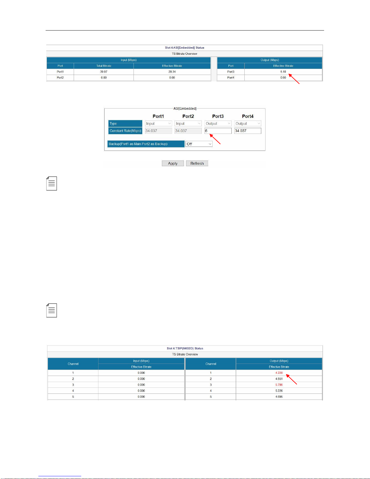
Go to Status > ASI [Embedded]. Verify the output Effective Bitrate of this ASI port.
Page 18
SMP100 User Guide
12
Go to Module Configuration > ASI [Embedded]. Set the Constant rate of this port. Click Apply.
EMM and Other PIDs (EIT, SDT, TDT and other PIDs) can be output by drag-and-drop
procedures.
Embedded TSIP Output
The steps to configure IP output are similar to the ways to configure ASI output:
1. Go to Module Configuration > TSIP [Embedded]. Open output channels and set output
parameters.
2. Distribute services in Service Configuration page.
3. Verify the output bitrate in Status.
4. Set the Constant Rate in Module Configuration for the output channels.
If the Constant Rate is lower than the Effective Bitrate at a time, it will cause packet loss
issue. In that case, the Effective Bitrate of the corresponding output TS will be highlighted in red.
See the following image.
Page 19

SMP100 User Guide
13
3.2.5 Delete an Output TS/Program/PID
Move the cursor to a TS, Program or PID until a red icon ( ) appears. Click the red icon to delete
the service or PID. Click Apply before next step.
3.2.6 Version Information/Upgrade
Version Information/Upgrade page presents the software information. Check Advanced to view
all the software that are loaded in this unit.
Updating software
Click Browse to select the software. Then click Upgrade to start update process.
If it is a mainboard upgrade, SMP100 will reboot itself after upgrade is finished. If it is module
upgrade, Go to Module Configuration and click Reboot to load the module again.
Page 20

SMP100 User Guide
14
Always contact provider if you have any software problem. Do not click Erase All to delete all
the software unless instructed to do so.
Do not upgrade any software unless instructed to do so. Do not disconnect the management
cable or power off the device during update process.
3.2.7 License
License page is where to check and update licenses. Note slot 0 refers to the Mainboard.
Updating License
1. Click Browse to select a license file.
2. Click the circle to select a slot number, then click Export License to save the license in the
computer. Better name the license files as smp241main.License, so that you know which license
is for which module in which unit.
3. Send the license file to the provider for update.
4. Once you have the new license file. Click Browse to select a license file in the computer, then
click Upgrade License to enter update process. When the update process succeeded, a
manual restart is required to activate the new license.
The license file is unique for each module. You are not supposed to export a license file from
one unit and upgrade it in another unit. Contact your provider if you need license updates.
Page 21

SMP100 User Guide
15
3.2.8 Import/Export Configuration
Export the configuration of a unit, then you can Import it to this unit for fast configuration recovery
when needed. To import the whole configuration from the sample unit to other duplicate units, the
module types and their positions in the duplicate units should be exactly the same with that in the
sample unit.
3.2.9 Login User Management
By default, the administrator user name and password are both admin. If the admin password is lost
or admin user is deleted, you will have to perform factory setting on the front panel by pressing the
buttons to restore the default login account. In that case, you will lose the configuration of this unit.
3.2.10 Log
Log records the operations and activities of a SMP100. We may request an exported log file from
user for troubleshooting or other use.
Page 22

SMP100 User Guide
16
3.3 Advanced Operations
3.3.1 Edit Output TS
Right-click any output TS and select Edit TS Info.
When the Output TS Standard in the System page is DVB, you have the following editable items.
Name
Range
Name
Range
Original Network ID
0~65535
Service Type
0~255
TS ID
0~65535
ES PID
32~8190
Service Name
Max 32 letters
Priority
1, 2, 3
Provider Name
Max 32 letters
Running Status
0~7
Service ID
0~65535
Free CA Mode
0~1
PMT PID
32~8190
EIT Schedule Flag
0~1
PCR PID
32~8190
EIT Present Following Flag
0~1
Page 23

SMP100 User Guide
17
PID 8191 is taken as the PID for null (stuffing) packets.
When the Output TS Standard in the System page is ATSC, you have the following editable items.
Name
Range
Name
Range
Service Name
Max 32 letters
ES PID
32~8190
Service ID
0~65535
Running Status
0~7
Channel Number
Format: x-x
Free CA Mode
0, 1
Channel TS ID
0~65535
EIT Schedule Flag
0, 1
PCR PID
32~8190
EIT Present Following Flag
0, 1
Service Type
0~255
3.3.2 Edit Service Information for DVB Output
Right-click an output TS to enter SI Setting (DVB).
Page 24

SMP100 User Guide
18
Add Network Information Table (NIT)
See the following image. Board3 [QAM A/C] is streaming output TS1, TS2 and TS3. Original
Network ID is 1. TS ID’s are 1, 2 and 3. The frequency of TS1 is 474000 KHz, and TS2 482000
KHz, TS3 490000 KHz. Suppose 474 MHz (TS1) is the center frequency.
Steps to add NIT:
1. Right-click NIT Actual to edit Network ID and Network Name.
2. Right-click transport_streams to add TS1 (Original Network ID:1 and TS ID:1) .
Page 25

SMP100 User Guide
19
3. Right-click transport_descriptors in transport_stream_id:1 to add Cable Descriptor for TS1.
4. Repeat Step 2 to add TS2 and TS3. Repeat Step 3 to add cable descriptors for these two TS’.
5. Click Apply, and go to Service Configuration page, click Apply again.
Right-click version_number to change its value if necessary. Once you have added NIT, you
are able to export it. Wherever you can find the cross icon ( ), you can click this icon to delete that
item.
Page 26

SMP100 User Guide
20
Add Logical Channel Number (LCN)
LCN is used to sequence the channels in the Set Top Box. See the following image, we have a SI
tree with Cable Descriptors added in transport_stream_id:1, transport_stream_id:2,
transport_stream_id:3.
Steps to add LCN for the output services (CCTV2, CCTV7, CCTV10, CCTV11, CCTV 12, and
CCTV15):
1. Right-click transport_descriptors under transport_stream_id:1, then select Add LCN
Description to enter edit page.
TS1 with Cable Descriptor
TS2 with Cable Descriptor
TS3 with Cable Descriptor
Page 27

SMP100 User Guide
21
2. Select Board1 [QAM (A/C)], Port1, TS1 by clicking the circle in front of it. Then CCTV2 and
CCTV7 in TS1 will be in Services box on the right side. Click Add in front of CCTV2 (service ID
302) and CCTV7 (service ID 303), they will be added to LCN box. Enter numbers in Logic
Channel Number text field. Click Add, then Exit.
Page 28

SMP100 User Guide
22
3. Check the LCN descriptors of CCTV2 and CCTV7 that you configured.
4. Right-click transport_descriptors under transport_stream_id:2, then select Add LCN
Description. Select Board1 [QAM (A/C)], Port1, TS2 add LCN for CCTV10 (service ID 304)
and CCTV10 (service ID 305). Click Add and Exit.
Page 29

SMP100 User Guide
23
5. Repeat Step 4 to add LCN for CCTV12 and CCTV15 under transport_stream_id:3. Once you
have added LCN for these 6 services, click Apply in the following page.
6. Go to Service Configuration.
Click Apply and Save.
Page 30

SMP100 User Guide
24
3.2.2 Upgrading STB through SMP
To update the software for a number of STB’s, use the following steps:
1. Feed the update stream to SMP by the embedded ASI or IP port.
2. Drag the update PID to QAM output port. See the following image, an update stream is taken as
other PID 8001 in SMP.
3. Add update descriptor in the NIT. Go to SI Edit page of the center TS. Add Network Descriptor
by right click on network_descriptors. Generally, the descriptor is from STB manufacturer.
4. Click OK to confirm. See the following image, the update descriptor is crated under NIT Actual.
5. Go to Service Configuration. Click Apply and Save.
Page 31

SMP100 User Guide
25
Part 4 Module Configuration
4.1 Input and Output Modules
4.1.1 ASI
ASI is a 4-channel ASI I/O module. Each ASI port can be set as either input port or output port
separately.
Module configuration > ASI
Name
Range
Description
Type
Input, Output
Select to determine the port to be input or output.
Constant Rate (Mbps)
0~100
Max rate of ASI is 100Mbps
PCR Adjust Mode
Wellav Adjust Mode
Real-time Stamp Mode
Page 32

SMP100 User Guide
26
4.1.2 DVBC
DVBC is a 4-channel DVBC receiving module.
Module Configuration > DVBC
Name
Range
Frequency (KHz)
48000~870000
Symbol Rate (KSym/s)
3000~7000
Constellation
QAM16/32/64/128/256
Lock Status
Lock/Un-lock
Page 33

SMP100 User Guide
27
4.1.3 DVBS2
DVBS2 is a 4-channel DVBS2 receiving module.
Module Configuration > DVBS2 (V2)
Name
Range
Description
Mode
4CH Mode(Normal)
2CH Mode(Advanced)
4CH Mode: QPSK, 8PSK
2CH Mode: QPSK, 8PSK, 16APSK,
32 APSK.
Symbol Rate (Ksym/s)
1000~45000
Page 34

SMP100 User Guide
28
LNB Type
Single Band, Dual Band
Band Selection
Auto, Forced Low, Forced High
Bias
Disable/Enable
Available in Port2 and Port4
Polarization
13V (V)
18V (H)
Vertical
Horizontal
Lock Status
Lock/Un-lock
To indicate the input is locked or not.
Contact service provider for input information or visit www.lyngsat.com for the latest information of
satellite Radio & TV channels.
4.1.4 DVBT2
DVBT2 is a 4-channel DVBT/DVBT2 receiving module.
Module Configuration > DVBT2
Page 35

SMP100 User Guide
29
Name
Range
Description
Tuner Mode
DVB-T
DVB-T2
DVB-T: QPSK, 16/64QAM
DVB-T2: QPSK, 16/64/256QAM
Frequency(KHz)
48000~862000
Bandwidth
6M, 7M, 8M
Depends on the standard in your country.
PLP Mode
A, B
Available when Tuner Mode is DVB-T2.
PLP ID
Available when PLP Mode is B.
4.1.5 8VSB
8VSB is a 4-channel 8VSB receiving module.
Module Configuration > ATSC
Page 36

SMP100 User Guide
30
Name
Range
Description
Channel
57~803MHz
Refer to American ATSC (8-VSB) Channel List
4.1.6 QAM
QAM module supports modulating 8 adjacent channels. The left connector is for local monitoring.
Module Configuration > QAM
Page 37

SMP100 User Guide
31
Name
Range
Name
Range
RF Level(dBuV)
90~106
Enable
Disable, Enable
Bandwidth
6M, 7M, 8M
Frequency (KHz)
47000~862000
Symbol Rate (KBaud)
4400~6956
Constellation
QAM64/128/256
Spectrum Shaping
Disable, Enable
Max Rate (Mbit)
Automatically calculated
4.1.7 IQAM
IQAM module supports modulating 16 non- adjacent channels.
Module Configuration > IQAM
Page 38

SMP100 User Guide
32
4.1.8 OFDM
OFDM is a 4 channel modulating module. The left connector is for local monitoring.
Module Configuration > OFDM
Name
Range
Name
Range
Bandwidth
6M, 7M, 8M
Guard Interval
1/4, 1/8, 1/16, 1/32
RF Level(dBuV)
90~109
Mode
2k, 8k
Spectrum Shaping
Disable/Enable
Constellation
QPSK, QAM16/64
Enable
Disable/Enable
FEC HP
1/2, 2/3, 3/4, 5/6, 7/8
Frequency (KHz)
40000~862000
Max Rate (Mbit)
Automatically calculated
Page 39

SMP100 User Guide
33
4.1.9 8VSBM
8VSBM is compliant with the modulation method used for broadcast in the ATSC digital television
standard.
Module Configuration > ATSCM
Name
Range
Name
Range
RF level
80~107 dB, -27~0 dBm
Channel Select
57~803 MHz
Spectrum Shaping
Disable, Enable
Frequency (KHz)
44000~999000
Channel Plan
OTA, STD, IRC, HRC
Page 40

SMP100 User Guide
34
4.1.10 HDMI/SDI Decoder
HDMI/SDI Decoder supports decoding 2 programs in two HDMI ports and two SDI ports.
Module Configuration > HDMI/SDI Decoder
Name
Range
Name
Range
Aspect Ratio
Conversion
Automatic
4:3 Letterbox
4:3 Pan and Scan
16:9 Letterbox
16:9 Pan and Scan
Output Resolution
1920x1080_50i/60p/59.94p/
59.94i/60i/30p/29.97p/24p
1280x720_60p/50p/59.94p
720x480_60i
720x576_50i
Audio Volume (0-49)
0~49
One decoder channel decodes only one service.
Page 41

SMP100 User Guide
35
4.1.11 Decoder-AV
Module Configuration > Decoder-AV
Name
Range
Name
Range
Aspect Ration Conversion
4:3 Letterbox
4:3 Pan and Scan
16:9 Letterbox
16:9 Pan and Scan
Audio Volume
0~49
Output Video Resolution
720x576_50i
720x480_60i
Mixer
Stereo, Left, Right,
Mono, Dual
One decoder channel decodes only one service.
Page 42

SMP100 User Guide
36
4.1.12 ASI-Switch
ASI-Switch is a 3in2out board for ASI input redundancy application. The three ports on the right are
primary, secondary (it could be a copy of the main), and fail-safe input. The two ports on the left are
both output 1 and output 2 interfaces.
Steps to get input services:
1. Connect ASI cables with valid signals to the three ASI input ports.
2. Go to Service Configuration, scan the three input TS. You will see the input TS’ as in the
following image.
3. Click Apply and Save button in this page.
4. Go to Module Configuration > SWITCH. Set the switching conditions and thresholds.
Module Configuration > SWITCH > Backup
By default, Switch level settings is Port-level, and Port-switch mode selection is Automatic
switch. See the following image. Automatic switch means this unit will monitor the input according
to the conditions that has been checked in Port-switch condition selection.
Page 43

SMP100 User Guide
37
Some options in Port automatic switch settings:
Automatic switch mode
Use Primary program first, this module will activate switch
function. Select Switch Lock to disable this feature.
Min/Max total bitrate of primary,
secondary and fail-safe port
Configure Minimum and Maximum rates to define the
normal rate ranges for the input ports.
Switch-back delay
Once the primary recovered, this module will switch to
primary input after a scheduled period.
If you use Manual switch for Port switch mode selection, the UI will be the following image.
Page 44

SMP100 User Guide
38
If you choose Program-level for Switch level settings, the UI will be like this:
As you can see in the image above, you have to configure Program-switch condition selection
and Program Setup.
Module Configuration > SWITCH > Output
ASI Out 1 bitrate
Configure the constant bitrate for the output ASI port 1. This constant rate
should be larger than the effective rate of the input streams.
Other output port
bitrate
Configure the constant bitrate for the output ASI port 2. This constant rate
should be larger than the effective rate of the input streams.
Output stream
selection of other
output ports
ASI Switch module will output one of the following four inputs even the whole unit
is off: Same signal output as ASI Out 1, Pass-through ASI In 1 (Primary), Passthrough ASI In 2 (Secondary), Pass-through ASI In 3 (Fail-safe)
Pass-through
mode for power off
ASI Switch module will output one of the following three inputs even the whole
unit is off: Pass-through ASI In 1 (Primary), Pass-through ASI In 2 (Secondary),
Auto
Page 45

SMP100 User Guide
39
4.2 Encoding Modules
4.2.1 EN4AV-4M2B
EN4AV-4M2B is a 4-channel CVBS encoder that supports H.264 and MPEG-2 encoding. It can be
licensed to support MPEG-2 encoding only.
Module Configuration > EN4AV-4M2B
Page 46

SMP100 User Guide
40
Name
Range
Name
Range
Video Encoder Type
H264, MPEG2
PCR PID
32~8190
Audio Encoder Type
OFF,MPEG1_Layer2, MPEG4_AAC
AC3 (optional), MPEG2_AAC
Video PID
32~8190
Video Encode Mode
CBR, VBR
Audio PID
32~8190
Video Max Encode Rate
1.5~2 times of Video Encode Rate
PMT PID
32~8190
Video Min Encode Rate
0~0,75times of Video Encode Rate
Program Name
Max 32 letters
Video Encode Rate
600~6000
Provider Name
Max 32 letters
Audio Encode Rate
64~384
Video Vlc Mode
CABAC, CAVLC
Total Encode Rate
Automatically Calculated
Video Profile
Main, High
Audio Volume
0~8
Video Level
3.0, 3.1, 3.2, 4.0, 4.1, 4.2
GOP Structure
IBBP, IPPP, IBP
Brightness
0~255
GOP Size
6~63
Contrast
0~255
GOP Close
Enable, Disable
Saturation
0~255
Hue
-180~180
Page 47

SMP100 User Guide
41
4.2.2 EN4SDI-2M2A
EN4SDI-2M2A module supports encoding 2 H.264 HD/SD channels or 2 MPEG-2 SD channels via
SDI/CVBS input. AAC and AC3 audio encoding is available with optional hardware and license.
Module Configuration > EN4SDI-2M2A
Page 48
SMP100 User Guide
42
Name
Range
Name
Range
Video Source
SDI
CVBS
Aspect Ratio
Automatic, 16x9_LetterBox
16x9_CutOff, 4x3_PillarBox
Video Encoder Type
H264, MPEG2
Video Standard
Auto, Downscale
Video Encode Rate
(Payload)(Kbps)
600~6000
PCR PID
32~8190
Video Encode Mode
CBR, VBR
Video PID
32~8190
Video Max Encode
Rate (Payload)(Kbps)
1.5~2 times of Video
Encode Rate
Service PID
32~8190
Video Min Encode
Rate (Payload)(Kbps)
0~0,75 times of Video
Encode Rate
PMT PID
32~8190
Audio Source
Program Name
Max 32 letters
Audio Encoder Type
OFF, MPEG1_Layer2
AC3 (optional)
Provider Name
Max 32 letters
Page 49

SMP100 User Guide
43
MPEG2_AAC
MPEG4_AAC
AC3 AC Mode
1+1
Latency adjustment
(ms)
Enter a value to adjust the
audio and video
synchronization. Enter a
positive value to delay audio
encoding.
Audio Encode Rate
(Payload)(Kbps)
64~384
Vlc Mode
CABAC
CAVLC
Belong to
Program-1
Profile
Main, High
Audio Volume
0~8
Level
3.0, 3.1, 3.2, 4.0, 4.1, 4.2
Audio PID
32~8190
Sample Rate
32KHZ, 44.1KHZ,48KHZ
GOP Structure
IBBP, IPPP, IBP
Brightness
0~255
GOP Size
6~63
Contrast
0~255
GOP Close
Enable, Disable
Saturation
0~255
Hue
-180~180
4.2.3 EN4HDMI-xM2A
EN4HDMI-4M2A supports encoding 4 H.264/MPEG-2 SD channels or 4 H.264 HD channels.
EN4HDMI-2M2A supports encoding 2 H.264/MPEG-2 SD channels or 2 H.264 HD channels. AAC
and AC3 audio encoding is available with optional hardware and license.
Page 50

SMP100 User Guide
44
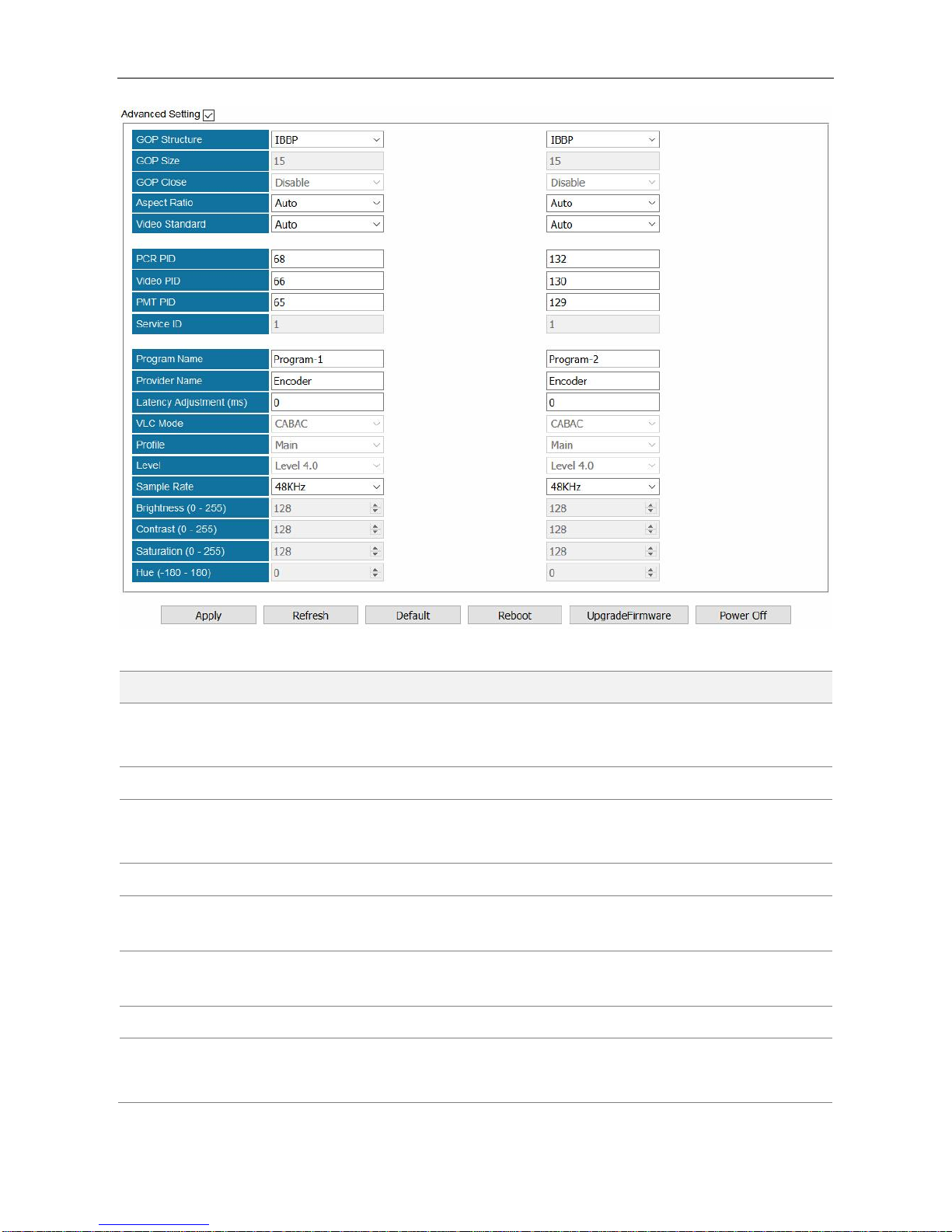
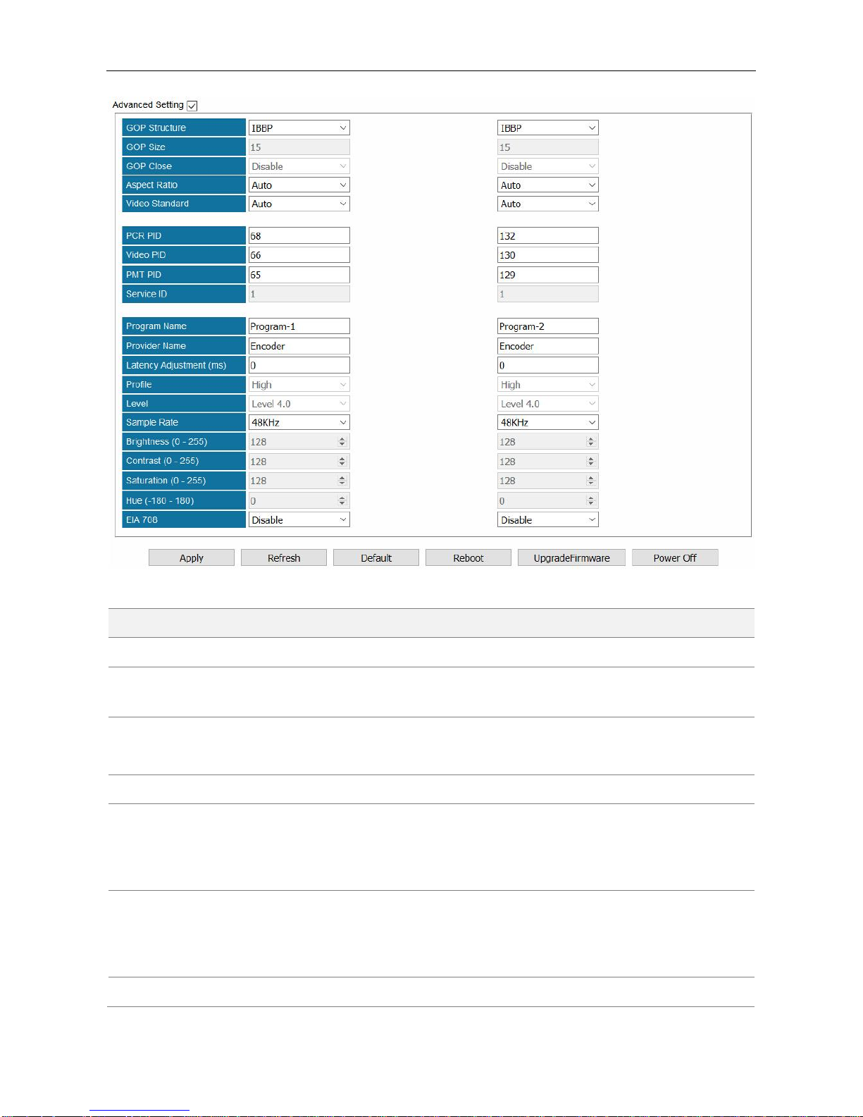
Module Configuration > EN4HDMI-4M2A
Page 51

SMP100 User Guide
45
Name
Range
Name
Range
Video Encoder Type
H264, MPEG2
GOP Structure
IPPB, IPPP, IBP
VLC Mode
CABAC, CAVLC
GOP Size
6~63
Profile
Main, High
GOP Close
Disable, Enable
Level
3.0, 3.1, 3.2,
4.0, 4.1, 4.2
Sample Rate
32KHZ, 44.1KHZ,
48KHZ
Video Encode Rate
(Payload)(Kbps)
Video Standard
Auto
Downscale
Video Encode Mode
CBR, VBR
Aspect Ratio
Automatic
16x9_LetterBox
16x9_CutOff
4x3_PillarBox
Video Max Encode
Rate (Payload)(Kbps)
1.5~2 times of Video
Encode Rate
PCR PID
32~8190
Video Min Encode Rate
(Payload)(Kbps)
0~0,75 times of Video
Encode Rate
Video PID
32~8190
Audio Encoder Type
OFF, MPEG1_Layer2
AC3 (optional)
MPEG2_AAC
MPEG4_AAC
PMT PID
32~8190
AC3 AC MODE
1+1(L, R)
1/0(C)
2/0(L, R)
Program Name
Max 32 letters
Audio Encode Rate
(Payload)(Kbps)
48~448
Provider Name
Max 32 letters
Audio Volume
0~8
Source Check
Disable, Enable
Audio PID
32~8190
Encoder Rate Check
Disable, Enable
The Status >EN4HDMI only presents the Video Resolution when of the input content is
protected by HDCP. In that case, the Total Bitrate and Effective Bitrate will be 0.000 Mbps and
Scan TS will fail.
Page 52

SMP100 User Guide
46
4.2.4 EN2SDI-2H
EN2SDI-2H is a 2-channel H.264/MPEG-2 HD/SD encoder via SDI/CVBS input.
Module Configuration > EN2SDI-2H
Page 53
SMP100 User Guide
47
Name
Range
Name
Range
Video Source
SDI, CVBS
Video PID
32~8190
Video Encoder
Type
H264, MPEG2
PMT PID
32~8190
Video Encode Rate
(Payload)(Kbps)
600~20000
Service ID
0~65535
Video Encode Mode
CBR, VBR
Program Name
Max 32 letters
Audio Source
L1-XLR1-R1,SDIx-Audio1/2
SDIx-Audio3/4,SDIx-Audio5/6
SDIx-Audio7/8
Provider Name
Max 32 letters
Audio Encoder
Type
OFF, MPEG1_Layer2
AC3 (optional), MPEG2_AAC
MPEG4_AAC
Latency
Adjustment (ms)
Enter a positive value to
delay audio encoding.
Belong to
Progrma-1
Profile
Main, High
Page 54

SMP100 User Guide
48
Audio Volume
0~8
Level
3.0, 3.1, 3.2, 4.0, 4.1, 4.2
Audio PID
32~8190
Sample Rate
32KHZ, 44.1KHZ,48KHZ
GOP Structure
IPPB, IPPP, IBP
Brightness
0~255
GOP Size
6~63
Contrast
0~255
GOP Close
Disable, Enable
Saturation
0~255
Aspect Ratio
Auto, 16x9_LetterBox
16x9_CutOff, 4x3_PillarBox
Hue
-180~180
Video Standard
Auto, Downscale
EIA 708
Disable, Enable
PCR PID
32~8190
4.3 Transcoding Modules
4.3.1 TC4-xM2A
TC4-xM2A module refers to TC4-2M2A or TC4-4M2A modules. TC4-2M2A supports transcoding to
2 H.264 HD/SD channels or 2 MPEG-2 SD channels. TC4-4M2A supports transcoding to 2 H.264
HD/SD channels or 4 MPEG-2 SD channels. AAC and AC3 audio encoding is available with
optional hardware and license.
Module Configuration >TC4-XM2A01
Page 55

SMP100 User Guide
49
Name
Range
Name
Range
Video Encode Rate
(Payload)(Kbps)
600~15000
Video Profile
Main, High
Audio Encode Rate
(Payload)(Kbps)
64~384
Video Level
3.0, 3.1, 3.2,
4.0, 4.1, 4.2
Audio Volume
(Transcode)(dB)
0~8
Video Vlc Mode
CABAC, CAVLC
GOP Structure
IPPB
IPPP
IBP
Audio Encoder Type
OFF, MPEG1_Layer2
AC3 (optional)
MPEG2_AAC
MPEG4_AAC
Page 56

SMP100 User Guide
50
GOP Size
6~63
AC3 AC Mode
1+1(L, R)
1/0(C)
2/0(L, R)
GOP Close
Disable, Enable
Aspect Ratio
Conversion
Automatic, 16x9_LetterBox
16x9_CutOff, 4x3_PillarBox
4x3_CutOff
Same PID for PCR
and Video
Video Max Encode Rate
(Payload)(Kbps)
Output Resolution
720x480_60i
720x576_50i
1920x1080_60i/50i
1208x720_60p/50p
Video Min Encode Rate
(Payload)(Kbps)
Video Encoder
Type
H264, MPEG2
Latency Adjustment
(ms)
Enter a value to adjust the audio
and video synchronization. Enter
a positive value to delay audio
encoding. Enter a negative value
to hasten audio encoding.
SDHD
4SD/2HD channel mode.
Drag a program to a TC4 output port for transcoding process. The transcoded program will be in the
corresponding TC4 input port. Then the transcoded program can be sent to an output port.
Page 57

SMP100 User Guide
51
4.4 Scrambling/Descrambling Modules
4.4.1 CI Descrambling
One CI module allows the user to insert two pairs of CAM and smartcard into two independent slots.
The top slot is slot 1. The bottom slot is slot2. The user can either select Auto Reset or click Reboot
to reset CAM modules. MMI button is used to read CAM and smartcard information.
Module Configuration > CI
Configuring Service Descrambling
In the following image, a TS that contains 9 scrambled services comes from ASI input port.
1. Go to Status > CI and check the CAM Insert Status, CAM Initialization status, CAM Name,
and CA System ID. Take the following figure for example, the CAM module is successfully
loaded in CI Port.
Page 58

SMP100 User Guide
52
2. Go to Service Configuration. Bypass the input TS and drag it to output Board3 [CI] on the
right side. Then on the left side in Board3 [CI] Port1 the processed TS is listed as an input
again.
3. Right-click a program in the output CI port to descramble this service by the CAM in Port 1.
[Descramble] follows the service that is descrambled as a mark. To cancel the descrambling
process for the service, right-click it and click Non-descramble. Click Apply.
4. Drag the service that has been descrambled from input Board3 [CI], Port1 to output port.
Page 59

SMP100 User Guide
53
5. Go to Status > CI, check the Service Descramble Status. In the following figure, three services
are descrambled successfully.
Page 60

SMP100 User Guide
54
4.4.2 CI-BISS Descrambling
CI module can be converted to CI-BISS module by a different license and loading CI-BISS module
software. BISS descrambling does not require any CAM module. Use the similar way as in Chapter
4.2.1 CI Descrambling to configure CI-BISS Descrambling.
1. Bypass the input TS and drag it to output CI port.
2. Right-click a program and click BISS-Descramble.
3. Configure BISS Mode and BISS Key (and Injected ID in BISS-E Mode). Click Apply and then
click Back to return to Service Configuration. [BISS_1] and [BISS_E] follow the descrambled
services as a label.
Page 61

SMP100 User Guide
55
4. Drag the descrambled services to output port.
5. Check descrambling status in Status > CI.
To ensure CA PMT is updated in CI, better bypass the input TS before drag it to CI. Otherwise,
descrambling process may fail.
4.2.3 Scrambler
The scrambler module is use to work with CAS systems to encrypt programs. It supports scrambling
up to 150 services. Besides, it support BISS-1/BISS-E scrambling without extra license. AES-CBC
mode is optional.
Page 62

SMP100 User Guide
56
Overview of Scrambler+ menu structure:
Configuring Scrambler+ Setup
Go to Module Configuration >Setup. Enter the IP Address, Subnet Mask, Gateway, and Speed
Mode for this scrambler. The IP Address should be in the same network with that of the CAS
server. The Speed mode should be the same with the Ethernet of CAS server. Turn on CA System
1 and keep unused CA Systems Off. Use a cross-through RJ45 cable to connect scrambler to CAS
server’s Ethernet port. Check the connection by pinging scrambler’s IP address in the Command
Prompt of CAS server.
Configuring ECMG connection.
Enter System ID, Sub System ID (keep it 0 if not required), ECMG IP Address, and ECMG Port.
Click Apply. Check ECMG Communication Status in Status > Scrambler+. When the connection
is liable, the status is a green Connected. See in the following figure.
Page 63

SMP100 User Guide
57
Configuring EMMG connection.
Enter EMMG TCP Port, EMMG UDP Port (keep it 0 if EMM Send Type is TCP), EMM Send Type,
EMM PID, and EMM Bandwidth. Click Apply. Check EMMG Communication Status in
Status >Scrambler+. When the connection is stable, the status should be a green Connected.
Configuring ECM
Add the AC Data that is created in CAS server into ECM List.
Page 64

SMP100 User Guide
58
Scrambling Programs
Once the ECMG, EMMG connection is done and ECM is added, go to Service Configuration and
right-click a program in output port to Program Scramble Setting.
Select Slot (the slot in which Scrambler+ is installed), CA Stream ID for each program and click
Apply to scramble them. Go to Status > Scrambler+ and check ECM Count. The count number
should be the same with the number of scrambled programs.
To cancel the scrambling process for a scrambled program, go to Program Scramble Setting
again, change Slot to None and apply Non-scramble for this program.
BISS-1/BISS-E Scrambling
BISS scrambling does not require a CAS server. Right-click an output program to Program
Scrambling Setting. Select BISS-1/BISS-E in Scrambling Type and enter BISS keys to scramble
the programs.
Page 65

SMP100 User Guide
59
Part 5 Appendices
Appendix A - Abbreviations
8VSB
Vestigial sideband modulation with 8 discrete amplitude levels
16VSB
Vestigial sideband modulation with 16 discrete amplitude levels
AAC
Advanced Audio Coding
AC-3
Also known as Dolby Digital
ASI
Asynchronous Serial Interface
ATSC
Advanced Television Systems Committee
AV
Audio Video
BAT
Bouquet Association Table
BER
Bit Error Ratio
Bit Rate
The rate at which the compressed bit stream is delivered
BNC
British Naval Connector
CAM
Conditional Access Module
CAT
Conditional Access Table
CAT6
Category 6 – Cable standard for gigabit Ethernet
CBR
Constant Bitrate
CI
Common Interface
CVBS
Composite Video Broadcast Signal
dB
Decibel
DVB
Digital Video Broadcasting
EIT
Event Information Table
EPG
Electronic Program Guide
FEC
Forward Error Correction
GOP
Group of Pictures
HD
High Definition
HDCP
High-bandwidth Digital Content Protection
HDMI
High Definition Multimedia Interface
I/O
Input/output
Page 66

SMP100 User Guide
60
Kbps
1000 bit per second
LCN
Logical Channel Number
LNB
Low-Noise Block
LO
Local Oscillator
Mbps
1,000,000 bits per second
MER
Modulation Error Ratio
MIB
Management Information Base
MPTS
Multi-program Transport Stream
NIT
Network Information Table
OFDM
Orthogonal Frequency-Division Multiplexing
PAT
Program Association Table
PCR
Program Clock Reference
PID
Packet Identifier
PMT
Program Map Table
PSI
Program Specific Information
PSU
Power Supply Unit
QAM
Quadrature Amplitude Modulation
QPSK
Quadrature Phase-Shift Keying
SD
Standard Definition
SDI
Serial Digital Interface
SDT
Service Description Table
SI
Service Information
SNMP
Simple Network Management Protocol
SNR
Signal Noise Ration
SPTS
Single Program Transport Stream
TDT
Time and Date Table
TS
Transport Stream
VBR
Variable Bitrate
Page 67

SMP100 User Guide
61
Appendix B – Modules Available In Different Regions
Check the following sheet to find out which modules are available for SMP100 in certain regions.
Module Name
North America
Europe
TSIP+
DVBC
DVBS2
DVBT2
8VSB
QAM-A/C
QAM-B
IQAM
OFDM
8VSBM
HDMI/SDI Decoder
EN4SDI
EN4HDMI
EN2SDI-2H
TC4
CI
CI-BISS
LQAM-A/C
LQAM-B
Available
Page 68

SMP100 User Guide
62
Appendix C - Warranty
We warrants this instrument against defects from any cause, except acts of God and abusive use,
for a period of 1 (one) year from date of purchase. During this warranty period, we will correct any
covered defects without charge.
Appendix D - After-Sales Support
Please contact our sales/regional representatives for any help, product information, and
troubleshooting.
Returning Products for Service
The SMP100 is a delicate piece of equipment and needs to be serviced and repaired by the
manufacturer. In order to expedite this process please carefully read the following items.
Confirm the required component
Before any product can be returned for service, the client ought to contact our sales representatives
and after-sales support department by means of email to confirm the need to return the product or
part of the product.
Collect the Serial Numbers to obtain RMA Number
Serial Number (SN) is printed on a label on the chassis and modules. To create a RMA number, SN
must be submitted to support department. Once the RMA number has been issued to the client, the
unit/component needs to be packaged and shipped back to the manufacturer. It’s best to use the
original box and packaging for the product but if this not available, check with the service
department for the proper packaging instructions. RMA Number should be specified in the delivery
bill or written on the package.
Do not return any power cables or accessories unless instructed to do so.
 Loading...