

Page 1

December 2018
8183A www.sencore.com | 1.605.978.4600 Revision 2.0
DMG 4000
Digital Media Gateway
User Manual
STATUS
USB
D1
10G
D2
10G 1G 1G
D3 D4
CTRL
STATUS
USB
D1
10G
D2
10G 1G 1G
D3 D4
CTRL
MODULAR
HI-DENSITY
HOT-SWAP
DMG
CTRL D1 D2
STATU S
USB
CTRL D1 D2
STATU S
USB
DMG
Page 2

Page | 2
Copyright
© 2018 Sencore, Inc. All rights reserved.
3200 Sencore Drive, Sioux Falls, SD USA
www.sencore.com
This publication contains confidential, proprietary, and trade secret information. No part of this document may be copied, photocopied,
reproduced, translated, or reduced to any machine-readable or electronic format without prior written permission from Sencore.
Information in this document is subject to change without notice and Sencore Inc. assumes no responsibility or liability for any errors or
inaccuracies. Sencore, Sencore Inc, and the Sencore logo are trademarks or registered trademarks in the United States and other
countries. All other products or services mentioned in this document are identified by the trademarks, service marks, or product names
as designated by the companies who market those products. Inquiries should be made directly to those companies. This document may
also have links to third-party web pages that are beyond the control of Sencore. The presence of such links does not imply that Sencore
endorses or recommends the content on those pages. Sencore acknowledges the use of third-party open source software and licenses
in some Sencore products. This freely available source code can be obtained by contacting Sencore Inc.
About Sencore
Sencore is an engineering leader in the development of high-quality signal transmission solutions for the broadcast, cable, satellite,
IPTV, telecommunications, and professional audio/video markets. The company’s world-class portfolio includes video delivery
products, system monitoring and analysis solutions, and test and measurement equipment, all designed to support system
interoperability and backed by best-in-class customer support. Sencore meets the rapidly changing needs of modern media by
ensuring the efficient delivery of high-quality video from the source to the home. For more information, visit www.sencore.com.
Page 3

Page | 3
Table Of Contents
1 Installation and Safety ....................................................................... 5
1.1 The DMG 4200 product ............................................................................................... 5
1.1.1 Ventilation .............................................................................................................. 5
1.1.2 Replacing the power supply module ...................................................................... 5
1.2 The DMG 4100 product ............................................................................................... 6
1.2.1 Ventilation .............................................................................................................. 6
1.2.2 Replacing the power supply module ...................................................................... 6
1.3 Safety Considerations ................................................................................................. 6
1.4 Power .......................................................................................................................... 7
1.4.1 Power supply rating ................................................................................................ 7
1.4.2 DMG 4200 with 1200W AC Power ......................................................................... 7
1.4.3 DMG 4200 with 1500W AC Power ......................................................................... 8
1.4.4 DMG 4200 with 1200W DC Power ........................................................................ 8
1.4.5 DMG 4100 with 750W AC power ........................................................................... 8
1.5 Laser Safety ................................................................................................................ 9
2 DMG Platform Architecture ............................................................. 10
2.1 User Interface ............................................................................................................ 10
2.2 Automation Interface ................................................................................................. 10
2.3 Unit Configuration ...................................................................................................... 10
3 General Configuration ..................................................................... 11
3.1 Connecting to the device ........................................................................................... 11
3.2 Configuration Desktop ............................................................................................... 11
3.3 “User Configuration” Application ............................................................................... 11
3.4 “Maintenance Center” Application ............................................................................. 12
3.5 Interface Configuration .............................................................................................. 12
3.5.1 IP Interface Application ........................................................................................ 12
4 IP Input Application ......................................................................... 14
4.1 Adding a new source ................................................................................................. 14
4.2 Searching for streams ............................................................................................... 17
4.3 Changing existing input(s) ......................................................................................... 17
4.4 Removing existing input(s) ........................................................................................ 17
4.5 Bitrate, CC and RTP indicators ................................................................................. 17
4.5.1 Detailed status (Bitrate and PSI) .......................................................................... 18
5 IP Output Application ...................................................................... 19
5.1 Adding new outputs ................................................................................................... 19
5.2 Source selection ........................................................................................................ 20
5.3 Destination selection ................................................................................................. 21
5.4 Action buttons ............................................................................................................ 22
5.5 Supported mapping modes ....................................................................................... 22
5.6 Changing attributes on active outputs. ...................................................................... 23
6 S2X Input Application ...................................................................... 25
6.1 Configuring a demodulator ........................................................................................ 25
6.1.1 Demodulator settings ........................................................................................... 26
6.1.2 Descrambling settings .......................................................................................... 26
6.2 Status ........................................................................................................................ 27
6.2.1 Demodulator status .............................................................................................. 27
6.2.2 Component status ................................................................................................ 28
7 Conditional Access.......................................................................... 29
7.1 ECM Generators ....................................................................................................... 29
7.1.1 Add new ECMG ................................................................................................... 29
7.2 EMM Generators ....................................................................................................... 30
7.2.1 Add new EMM generator ..................................................................................... 31
7.3 EMM Streams ............................................................................................................ 32
Page 4

Page | 4
7.3.1 Add a new EMM stream ....................................................................................... 32
7.4 Flow Scrambling Application ..................................................................................... 33
7.4.1 Create Access Control group ............................................................................... 34
7.4.2 Edit Access Control group.................................................................................... 35
7.4.3 Edit service ........................................................................................................... 35
8 Encoders .......................................................................................... 37
8.1 Configuration Flow .................................................................................................... 37
8.2 Profiles....................................................................................................................... 37
8.2.1 Encoder Video Profile .......................................................................................... 37
8.2.2 Audio Profile ......................................................................................................... 40
8.2.3 Encoder Colour Profile ......................................................................................... 41
8.2.4 Encoder VANC Profile .......................................................................................... 42
8.3 Encoder Services ...................................................................................................... 44
9 SDI over IP ........................................................................................ 48
9.1 SDI - Configuration application ................................................................................. 49
9.2 SDI - Input / Output flow configuration ...................................................................... 50
9.3 IP-Gateway setup with SDI->IP flows ....................................................................... 51
9.4 IP-Gateway setup with IP->SDI flows ....................................................................... 51
9.4.1 Selecting the source ............................................................................................. 51
9.4.2 Expected format ................................................................................................... 52
9.4.3 Status ................................................................................................................... 53
9.4.4 Status of multiple ports......................................................................................... 53
9.5 SDI TICO UHD (2022-6) ........................................................................................... 55
9.5.1 UHD Encoder ....................................................................................................... 55
9.5.2 UHD Decoder ....................................................................................................... 55
9.6 TICO HD Encoder (2110) .......................................................................................... 57
9.7 Stream Labels ........................................................................................................... 57
9.7.1 SDI input status .................................................................................................... 57
9.7.2 HD TICO Configuration ........................................................................................ 57
9.7.3 The TICO encoder configuration .......................................................................... 58
9.7.4 Audio configuration .............................................................................................. 58
9.7.5 2110-40 Ancillary data ......................................................................................... 59
10 ASI ..................................................................................................... 60
10.1 ASI - Configuration application .................................................................................. 60
10.2 ASI – Input flow configuration ................................................................................... 61
10.3 ASI - Output flow configuration ................................................................................. 61
10.4 ASI output port settings ............................................................................................. 61
10.5 ASI output status ....................................................................................................... 62
11 Decoders .......................................................................................... 63
11.1 Configuration Flow .................................................................................................... 63
11.2 Profiles....................................................................................................................... 63
11.2.1 Decoder Video Profile .......................................................................................... 63
11.3 Add Decoder Services ............................................................................................... 65
11.3.1 Input Service Selection ........................................................................................ 65
11.3.2 Decoder Selection ................................................................................................ 65
12 S2X Output Application ................................................................... 68
12.1 Port profiles ............................................................................................................... 69
12.2 Carrier ID ................................................................................................................... 69
12.3 Precorrection ............................................................................................................. 70
12.4 Adding services to a mux .......................................................................................... 70
12.4.1 Supported mapping modes .................................................................................. 70
12.5 Changing output attributes ........................................................................................ 71
Page 5

Page | 5
1 Installation and Safety
The DMG 4000-series products are designed to offer operators reliability and flexibility, and consists of a chassis in which a
number of modules can be installed. To cater to specific system requirements, the chassis can be configured to host functional
modules best suited for a given scenario.
DMG 4000-series products can be delivered in two chassis versions - 2RU chassis and a 1RU chassis. The product model DMG
4200 represents the 2RU chassis, while the product model DMG 4100 represents 1RU chassis.
1.1 The DMG 4200 product
The 2RU chassis has a total of 14 slots all of which can host functional insertion blades. Slot number S1 and S2 in the front are
dedicated to host the control/switch blades. The unit can be delivered with 1 or 2 control/switch blades. The remaining 12 slots
are identical and can be occupied by any of the other functional insertion blades available. A 2RU chassis including control/switch
blades, power supply connectors, and slots for insertion blades in the back, is shown in Figure 2.1 and 2.2. Power modules are
inserted from the back (figure 2.2, while the fan module is inserted in the front (placed above the control/switch blades). The
chassis can hold 2 power supply modules for redundancy purpose
STATUS
USB
D1
10G
D2
10G 1G 1G
D3 D4
CTRL
STATUS
USB
D1
10G
D2
10G 1G 1G
D3 D4
CTRL
MODULAR
HI-DENSITY
HOT-SWAP
DMG
Slot 1
Slot 2
Control/switch blade
Redundant control/switch blade
Slot #1A
OK
FAIL
OK
FAIL
Slot #3A
Slot #4A
Slot #1B
Slot #2B
Slot #3B
Slot #4B
Slot #1C
Slot #2C
Slot #3C
Slot #4C
3
9
12
1B4
7
10
13
5
8
11
14
6
1.1.1 Ventilation
The DMG 4200 product has forced air flow from front to back in the chassis, allowing for multiple units to be stacked above each
other with no space in between. However, adequate space must be provided in front of and behind the unit for effective
ventilation.
The DMG 4200 has 5 fans in front. Fan speed is temperature controlled. If one fan fails, remaining fans will increase speed to
compensate. The whole Fan module, containing all 5 fans, can be hot swapped. If, during fan module replacement, the
temperature on the inserted modules exceeds a certain critical temperature, the unit will shut down, to prevent damage of the
inserted modules.
1.1.2 Replacing the power supply module
The power supply modules for the DMG 4200 are hot-swappable. Under normal operating conditions they operate in load share
mode. In case of one power supply unit is failing, or there is a failure causing loss of power to one of the power supply units, the
Page 6

Page | 6
other power supply unit can feed the entire DMG 4200 product. Replacing one power supply will not affect the operation of the
unit. It is recommended to connect each power supply module to different circuits.
1.2 The DMG 4100 product
The 1RU chassis for the DMG 4100 holds of a total of 8 slot positions all of which can host functional insertion blades. Slot
number S1 and S2 in the front is dedicated to host the control/switch blades. The unit can be delivered with 1 or 2 control/switch
blades. The remaining 6 slots are identical and can be occupied by any of other the functional insertion blades available. A 1RU
chassis including control/switch blades, power supply connectors, and slots for insertion blades in the back, is shown in Figure
2.3 and 2.4. Power modules are inserted from the back (figure 2.4), while the fan module is inserted in the front (next to the
control/switch blades). The chassis can hold 2 power supply modules for redundancy purpose
Slot S1: Mandatory control/switch blade
CTRL D1 D2
STATU S
USB
CTRL D1 D2
STATU S
USB
DMG
Slot S2: Redundant control/switch blade
Slot #2A
Slot #1A
Slot #2B
Slot #1B
Slot #2C
Slot #1C
1A
2A2A
1B
2B2B
1C1C
2C
1.2.1 Ventilation
This DMG 4100 has forced air flow from front to back allowing for multiple units to be stacked above each other with no space in
between. However, adequate space must be provided in front of and behind the unit for effective ventilation.
The DMG 4100 has 6 fans in front. Fan speed is temperature controlled. If one fan fails, remaining fans will increase speed to
compensate. The whole Fan module, containing all 6 fans, can be hot swapped. If, during fan module replacement, the
temperature on the inserted modules exceeds a certain critical temperature, the unit will shut down, to prevent damage of the
inserted modules.
1.2.2 Replacing the power supply module
The power supply modules for the DMG 4100 are hot-swappable. Under normal operating conditions they operate in load share
mode. In case of one power supply unit is failing, or there is a failure causing loss of power to one of the power supply units, the
other power supply unit can feed the entire DMG 4100 product. Replacing one power supply will not affect the operation of the
unit. It is recommended to connect each power supply module to different circuits.
1.3 Safety Considerations
The unit must be connected to a grounded power connection. The power input connector) is a disconnect device. To remove
the power from the device, the power cables needs to be physically removed from the power input connector.
Mandatory Safety Instructions
Page 7

Page | 7
1
The equipment must be installed by a qualified person.
2
For that equipment with grounding, connect the driver before connecting the
power cord. For removal, the opposite must be done and the power cord
removed before removing the driver of the ground.
3
The equipment must be installed in a restricted area where:
• Only qualified technicians should have access.
• Access to the area where the devices are installed will be using a tool, lock
and key, or any other safety device, and in addition the site will be
controlled by an authorized person.
警告:接続ケーブルのプラグは、切断するためのものです。
電源プラグが常に手の届きやすい場所にくるように設置してください。
1.4 Power
1.4.1 Power supply rating
The DMG 4100 and DMG 4200 can be supplied with one of 3 different power supply options referred to as 1) 1200W AC power,
1500W AC power and 3) 1200W DC power.
Their ratings are:
1) 100-240V AC 50/60Hz 12-9A, Max load: 1200W for 200-240VAC / 800W for 100-200VAC
2) 100-240V AC 50/60Hz 15-10A, Max load: 1500W for 120-240VAC / 1260W for 100-120VAC
3) -48 to -60V DC Imax 36.2A, Max load: 1200W
The DMG 4100 is supplied with a 750W AC Power supply rated: 100-240 VAC 50/60Hz Imax 8.7A
1.4.2 DMG 4200 with 1200W AC Power
The 2RU chassis holds two power supplies with independent power inlet for the two supplies. The power inlet connector is IEC
type C14, requiring a Power cable with IEC type C13. Both supplies shall be connected and active. In case of one power supply
unit is failing, or there is a failure causing loss of power to one of the power supplies, the other power supply unit can feed the
entire DMG 4200 product.
Page 8

Page | 8
OK
FAIL
OK
FAIL
1.4.3 DMG 4200 with 1500W AC Power
The 2RU chassis holds two power supplies with independent power inlet for the two supplies. The power inlet connector is IEC
type C16, requiring a power cable with IEC type C15. Both supplies shall be connected and active. In case of one power supply
unit is failing, or there is a failure causing loss of power to one of the power supplies, the other power supply unit can feed the
entire DMG 4200 product.
OK
FAIL
OK
FAIL
1.4.4 DMG 4200 with 1200W DC Power
The 2RU chassis holds two power supplies with independent power inlet for the two supplies. The power inlet connector is a
screw terminal. Both supplies shall be connected and active. In case of one power supply unit is failing, or there is a failure
causing loss of power to one of the power supplies, the other power supply unit can feed the entire DMG 4200 product.
OK
FAIL
-
+
OK
FAIL
-
+
1.4.5 DMG 4100 with 750W AC power
The 1RU chassis holds two power supplies with independent power inlet for the two supplies. The power inlet connector is IEC
type C14, requiring a Power cable with IEC type C13. Both supplies shall be connected and active. In case of one power supply
unit is failing, or there is a failure causing loss of power to one of the power supplies, the other power supply unit can feed the
entire DMG 4100 product
Page 9

Page | 9
1.5 Laser Safety
The Optical SFP and SFP+ modules used in the DMG 4100 and DMG 4200 products are classified as class 1 laser products
according to IEC 60825-1 and are classified as class 1 laser products per CDRH, 21 CFR 1040 Laser Safety requirements.
Depending on the products configuration, the DMG 4100 and DMG 4200 products can be equipped with multiple insertion
modules containing housing for optical SFP and SFP+ modules.
When installing SFP/SFP+ modules, please ensure that the module be placed correctly in the housings present on the insertion
blades. Once inserted, the SFP/SFP+ module will become active.
Page 10

Page | 10
2 DMG Platform Architecture
The unit is designed with reliability and flexibility in mind. It consists of a chassis in which a number of hot-swappable
cards can be installed. The chassis can be configured to host interface and processing cards according to the customer’s
requirements.
Each switch module provides a backplane communication path which is used for data-transfer and inter-card
communication. Units with dual switch cards will thus provide two communication paths on the backplane. If one of the
switch modules fails, the other communication path is still active and communication and data-transfer between the
remaining cards will not be affected (seamless switching is applied internally).
2.1 User Interface
The main access point of a DMG device is via the control port of one of the switch cards. Once the username and
password are entered correctly the desktop will be accessible. The desktop is the main application launcher window.
Configuration of the unit is done via opening relevant applications. Card specific applications are running on the cards
themselves, so opening an application is essentially a web-redirect to the local card. Thus, it does not matter if you access
the card via switch card in slot 1 or 2, you end up on the same place anyway; on the card itself.
2.2 Automation Interface
The DMG platform offers an automation API (JSON) that supports all features offered via the WEB interface of the unit.
For easy integration with NMS systems the DMG unit also supports sending SNMPV2 traps to external NMS’s.
For details regarding the interface please contact Sencore.
2.3 Unit Configuration
All system configurations are store in a central database on the switch card. In the case of dual switch cards, the
databases are synchronized.
Page 11

Page | 11
3 General Configuration
3.1 Connecting to the device
In order to connect to the unit, you must first the control port to the PC/Network. The default IP address of the unit is
192.168.1.100.
• Set the IP address of the PC’s Ethernet to a fixed address in the same segment, e.g. 192.168.1.99
• Type the default IP address of the unit: https://192.168.1.100 in the web browser to display the user interface.
• Use default login user admin, without a password.
If the IP setting has been lost, a DIP Switch can be used to restore factory defaults.
3.2 Configuration Desktop
The desktop is the main application launcher and system status window. The upper part shows the hardware
configuration and key status regarding received and transmitted bitrate of the cards.
The centre part is the application launcher section. As applications are launched, they will appear along the lower edge of
the desktop for easy access later. In case of many applications the search window can be used to search for applications.
To revert to the desktop from an application press the icon in the lower left corner.
In the lower right corner, there is a red circle with a number. This represents the number of active alarms. Clicking the
circle will bring up the Alarms menu. The alarm history is accessible via the bell symbol, and the person symbol provides
info about the current user.
3.3 “User Configuration” Application
The user configuration application manages the user accounts. Custom users can be created and there are 4 different
user profiles available.
• Admin: All rights
• Expert: As Admin, but not allowed to configure interface IP addresses.
Page 12

Page | 12
• Engineer: As Engineer, but not allowed to add and remove flows in the system, only to change the content.
• Operator: View only rights.
To add a new user, press the + sign in the desired profile and add the credentials.
3.4 “Maintenance Center” Application
The Maintenance Centre application provides the toolkit for doing maintenance of the unit. The maintenance centre is a
global application interacting with all modules in the unit.
• Upgrade modules with new software
Please see the Upgrade Guide document for further information.
3.5 Interface Configuration
3.5.1 IP Interface Application
The IP interfaces application manages the IP interfaces of a module.
Open the IP interface application for the respective slot. For a switch card the control port will be listed in addition to the
data ports.
Page 13

Page | 13
For each port the following parameters are configurable:
Label
Assign a label for the port. This label will then be displayed in other views were
the port is referenced.
IPV4
Address
The IP address of the port. NB: For the IPV4 the address block 169.254.0.0/16
is reserved
Gateway
Gateway address of the interface
Netmask
Netmask of the interface in CIDIR subnet mask notation
I.e. /24 = 255.255.255.0
Port Mode
Select the physical format. RJ45, SFP(1Gbps) or SFP+ (10Gbps).
RX
Enable this if the port will be used to as an input port.
Only ports that are RX enabled will be a selectable port on the input configuration
application.
TX
Enable this if the port will be used as an output port.
Only ports that are TX enabled will be a selectable port on the input configuration
application.
Page 14

Page | 14
4 IP Input Application
The “IP input” application controls the IP input path of the IP chain.
When opening the application, it will list currently active inputs.
Enabled
The enable checkbox lets the operator easily disable an input. In a
multicast environment the IGMP message will not be sent such that
data is not forwarded from the switch.
Label
The label can be added during input definition, and changed directly
from the list view.
Mode
Indicates what type of content the system expects.
RTP / DVB/ MPEG
Services
The services detected in the streams. Valid for DVB and MPEG
sources only.
Interface
The actual interface where the stream is being received.
UDP
port
The port of the incoming stream.
Bitrate
Green of any bitrate is detected on the stream.
CC
errors
The number of times the CC counter has not been continuous.
RTP
errors
The number of times the RTP counter has not been continuous.
Red
Circle
Action button to remove streams
4.1 Adding a new source
To add new sources then left-hand pane can be expanded by hitting the arrow on the left-hand side of the page
Page 15

Page | 15
Label
Assign a label for the port. This label will then be displayed in other views
were the port is referenced.
No of Streams
The input application supports adding multiple sources simultaneously. The
maximum number of inputs: 2000
Increment
IP, Port or Port Groups
When adding multiple sources in a single operation this setting defines
which parameter to automatically increment
IP: The IP address will be increases
Port: The UDP port will be increased
Port Groups: The UDP port will be increment in groups.
Step Size: The increment within the group
Group Size: How any to add before a GAP in the count.
Group GAP: How many UDP port should be skipped between each
group.
Type
This tells the system what type of input is expected, hence what kind of
analysis may be performed on the incoming stream.
Additionally, it will affect the type of mapping that is supported by the
system. The IP source address will be re-generated by the DMG 4000.
DVB: Analyze PAT/PMT/SDT of the service
MPEG: Analyze PAT/PMT of the service
RTP: No analysis is performed. RTP inputs which are mapped out of the IP
chain will preserve the IP headers from the input.
Page 16

Page | 16
De-jitter
The de-jitter setting configures the de-jitter configurations depending on the
type of input data.
DVB/MPEG inputs
OFF: No de-jittering applied.
CBR->Bitrate: Optional parameter-. If the input rate is known, setting this
parameter will cause the input chain be quicker to get the rate-control
accurate.
PCR->Preferred PID: Optional parameter. If not set the unit will use one
which is signaled in the PMT.
RTP inputs
OFF: No de-jittering applied.
RTP: The RTP header is used for de-jittering. Note currently the timing
model supported is for 2022-6 content only. i.e. TS based sources cannot
be De-jittered using RTP mode.
De-jitter
Buffer(ms)
Both the MPEG/DVB and RTP inputs have a configurable input de-jitter
buffer. The default value of this buffer when not set is 100ms.
This buffer should be set to the jitter that needs to be compensated for,
allowing for an additional overhead.
In PCR dejitter mode the time should be set to at least twice the (PCR
interval + network jitter).
Seamless
input
When enabled the system is prepared to receive the same content via two
interfaces. The seamless input is linked to ports pairs. Both the 10G and
1G ports may be used with this mode.
Seamless mode:
Floating: The seamless logic will change the source only when the
currently selected source is faulty.
Path 1: The seamless logic will use input path1, if this source is not faulty
Path 2: The seamless logic will use input path2, if this source is not faulty
Seamless buffer size: Buffer size in milliseconds. 1->420 ms.
Buffer size assigned to the seamless input buffer logic. This buffer is in
before the dejitter buffer in the input chain.
Interface
Select the input interface. This list included the interfaces which are tagged
as RX enable in the interface configuration page.
IP / Port
The IP address and port of the incoming stream. This could be a multicast,
or a unicast. In the case of unicast, then use the IP address of the selected
interface.
IGMPV3
Source IP
In networks where PIM is not used, use this field to enter the source IP
address.
Page 17

Page | 17
4.2 Searching for streams
For an ever-increasing number of flows through a unit searching for information gets critical. In the DMG applications this
has been put into the system from the very start. On top of the input application pane there is a search field which enables
the operator to search and filter the list view in order to find the correct sources.
It is possible to search for text or dynamic attributes. Typical valid searches would be to look for a specific input multicast,
or look for all inputs with an alarm. The below picture shows some searches that are possible to do.
The result is a list view with a filtered amount of flows. Note that the search is a fuzzy search. So, the result will not
necessarily return only a 100% match, but will return the most relevant on top.
4.3 Changing existing input(s)
Once a source has been added it may be changed by selecting the stream to change from the list view. Multiple inputs
may be selected simultaneously for multi-edit operations Once a stream or multiple streams are selected the edit dialog
will be visible on the right-hand pane. The parameters are a subset of the parameters described above.
4.4 Removing existing input(s)
To remove an input, click on the red circle to the right in the list view. The selected stream will be stroked out with a red
line. Then hit Save at the bottom of the page.
Input analysis features
4.5 Bitrate, CC and RTP indicators
The IP-input application provides some basic input analysis of its defined inputs. The list view indicates if the input
contains any bitrate, cc errors or RTP errors. If bitrate is present then the bitrate indicator is green. If not its read.
Additionally, if any alarms are present, they will be displayed on the input view directly. Pointing to the Alarm indicator will
present more details.
To clear the CC and RTP counters us the “Clear counters” button at the bottom of the page.
Page 18

Page | 18
4.5.1 Detailed status (Bitrate and PSI)
On the right-hand side more stream details are shown. For MPEG/DVB sources the total bitrate for the input is shown.
The PID view lists the components signalled in the PMT, not the PIDs detected on the input. I.e. if there are any
unreferenced PIDs these will not be listed. If signalled PIDs are not present this will also generate a PID missing alarm.
For RTP sources the only status on the bitrate measurement.
Page 19

Page | 19
5 IP Output Application
To launch the IP output applications, locate the “IP Output (Slot Number)” application on the desktop for the slot in
interest and click the icon.
The start page of the output application lists the defined outputs.
Enabled
The enable checkbox lets the operator easily disable an output. The stream is still
defined in the system, but the stream output is muted.
Label
The label can be added during definition, and changed directly from the list view.
Mode
Indicates what type of content the system transmits.
• MPEG
• DVB - includes SDT
• RTP - TS over IP
• RTP (SMPTE2110)
• RTP(SMPTE2022-6)
Content
This column will display the service id + name (if available) for MPEG/DVB content.
For other types of content this column will list the type of mapping that is performed.
Interface
The actual interface where the stream is being transmitted.
IP
The destination IP address of the outgoing stream.
UDP port
The RTP port of the outgoing stream.
Red
Circle
Action button to remove streams from the output.
5.1 Adding new outputs
As for the input the output application the action buttons are located behind the expansion arrow on the left-hand side. To
add a new output, expend the left pane and select the source to be added. Add or change the required settings, then
press save to commit the changes. To discard non-saved changes, close the application.
Page 20

Page | 20
When the expansion dialog is open the next steps are to Select the source to add, select the destination of the source,
then the action buttons will be used to do the actual work. The following sections will dive into the details of each step.
5.2 Source selection
The source selection is the starting point to add new content. Start by selecting the type of content that shall be added.
The way content is added will tell the system how to map the data within the unit.
Source types
Service
Selecting the service selector then all services known to the system will be listed. Then
the source service of interest can be picked from the service list view.
TS
TS selector will show all MPEG/DVB transports known to the system. The source
transport of interest can be selected from the list of transports in the source list view.
When a TS source is mapped to an output the entire MPEG/DVB transport stream will be
mapped, including NULL packet.
Use the expansion arrow
to add locate sources
and add new content
Select the type of source to add.
Use the search engine to limit the number of sources
presented in the source list view.
Source list view. To change sort
ordering click the Column headers
The number of sources listed in the
source list view
Action button to add sources to and
output will activate when a source(s)
has been selected.
Use pagination buttons to see more
sources.
Page 21

Page | 21
Autofirst
In some system configurations the input is not present at the time of configuration of the
system. This is typically for VOD systems were the source is activated by the end user.
For this scenario the system must be configured in the same way as a service mapping,
only that the service to choose will be the first one that is detected on a source.
When doing an auto-first mapping the output service ID is by default set to 1 by the
backend software. This value can be overwritten by changing the outgoing service ID in
the edit output configuration dialog.
RTP
This type field will show only if RTP content is actually available in the unit. When
selecting the RTP source type the system will list all RTP flows in the system. This could
be input streams defined to be RTP, or it could be streams available from the SDI over IP
input card.
SMPTE
2110
The SMPTE2110 source type is a group where all the flows of a 2110 service are
encapsulated. Adding such a source will add all the flows part of the 2110 service. This
source type is delivered by the 2110 TICO HD encoder, but will also be constructed by
the IP input card when the TICO decoder is ready.
EMM
As for the RTP the EMM type selector is available only if EMMs are detected by the
system. Either from an input or from the scrambler card.
5.3 Destination selection
Where to output a source is decided by selecting the destination in the main list view. If a new output shall be created,
then simply use the create output action button. If the source shall be added to or replacing an existing output element
use the appropriate action button. The action buttons available at any given time depends on the selected input and
output elements.
The following figures shows how the action buttons varies in different in/out selection scenarios.
• With no destination selected the only action button available is the Create output
Page 22

Page | 22
• With a selected DVB output, then the Add to Multiplex action button appear
• With a selected output service, the Add to Multiplex disappears, and the Replace Content action button
appears.
5.4 Action buttons
Create output
Finalize the configuration before the changes are committed to the system.
Before the action is completed it is possible to review and complete the last pieces of the configuration. It is also possible
to do more advanced configuration such as component mapping etc. When all parameters are correct, use the Save
button in the lower right corner to commit the stream to the output.
5.5 Supported mapping modes
The action button which maps the selected source material to the output will change depending on the type of data to be
mapped, and depending on the destination of the content.
Cloned Output Enable this to mirror the output of Path1 to
path2.
Add Mode: The mode dictates how to generate the overall
attributes of the output.
SPTS: IP increment => Create SPTS output(s), increment the
IP address for each source if multiple sources are selected.
SPTS: Port increment => Create SPTS output(s), increment
the Port address for each source if multiple sources are
selected.
SPTS: Preserve Source Port => Create SPTS output(s), set the
Label: Add a label to the output flow.
Interface: Select the IP interface to which the output shall be
mapped. Cloned outputs are mirrored pairs. D1 is mirrored
on D2, D3 is mirrored on D4.
IP, Port and source address: Enter the destination IP
Add / Cancel: Add the selection to the output main page.
Note the action will not be committed until the save button
on the list view is applied.
Page 23

Page | 23
The system offers the following mapping modes.
Source
Action
Mapping action
Service
Create output
When a source service is created then a new DVB output is created.
By default, it is a VBR stream.
Service
Add to existing
output
With a service to transport mapping, use the Add to multiplex action
button, then the service will be added to the selected output transport.
Service
Replace a
service
Use the replace service to replace the destination service with the
selected source service.
TS
Create an
output
When a TS source is created the entire MPEG/DVB transport stream
will be mapped, including NULL packet.
Autofirst
Create/add or
replace
In some system configurations the input is not present at the time of
configuration of the system. This is typically for VOD systems.
When doing an auto-first mapping the output service ID is by default
set to 1 by the backend software. The source service selected is any
service detected on the source. If the source transport contains
multiple services any of the services, but only one, will be selected.
This value can be overwritten by changing the outgoing service ID in
the edit output configuration dialog.
RTP
Create an
output.
This type field will show only if RTP content is actually available in the
unit. When selecting the RTP source type the system will list all RTP
flows in the system. This could be input streams defined to be RTP, or
it could be streams available from the SDI over IP input card.
SMPTE
2110
Create an
output
The SMPTE2110 source type is a group where all the flows of a 2110
service are encapsulated. Adding such a source will add all the flows
part of the 2110 service. This source type is delivered by the 2110
TICO HD encoder, but will also be constructed by the IP input card
when the TICO decoder is ready.
EMM
Add to an
output
As for the RTP the EMM type selector is available only if EMMs are
detected by the system. Either from an input or from the scrambler
card.
5.6 Changing attributes on active outputs.
Configured outputs are listed in the main list view when opening the IP output application. The list view shows all streams.
As in the input application the search dialog can be used to limit the active selection.
To edit an output, click the object and the edit dialog will appear on the right-hand side.
Page 24

Page | 24
For DVB outputs
the transport layer edit dialog contains both the DVB transport and the IP specific parameters. Use multiselect to edit
multiple output streams simultaneously.
Selecting a service object will produce the following edit dialog.
Service ID
Optional. Use this to override the output service ID.
Service Name
Optional. Use this to override the output service ID.
Component filer
Use the component filter to stop and remap component PID values. Th e filter
can operate in PID to PID mapping or component type to PID mapping. The
filters are applied on chronological order.
For DVB services layer the edit dialog contains the DVB service parameters only.
Page 25

Page | 25
6 S2X Input Application
The “S2X input” application configures the demodulators on a given module. Each demodulator is represented as a row
in the main table view. Each row includes a subset of configuration and status of a demodulator. Expanding a row shows
a list of the services in the TS with service name and service ID. The “S2X interfaces” application configures the number
of demodulators per module and the LNB frequencies per port, as described in section X.X.X. When mapping a service
from the S2X input card to an output card; the slot, port, satellite frequency and TS label are used as source reference.
Enabled
The enable button lets the operator easily disable an input.
Port
The physical port in use. The label of the port is defined in the “S2X
Interfaces” application.
Label
A label of the transport stream (TS).
Mode
The configured analyze mode can be either MPEG or DVB.
Services
The number of services detected in the transport stream.
Satellite
Frequency
The configured satellite frequency.
Modcod
Status of detected modulation standard, constellation scheme and
FEC rate.
Symbol
rate
The configured symbol rate.
Lock
Green circle if the demodulator has achieved lock.
CC errors
The number of times the CC counter of any PID in the TS has not
been continuous.
6.1 Configuring a demodulator
Select a demodulator to display the “Details” pane on the right-hand side. Select the “Edit” tab to change configuration.
Page 26

Page | 26
6.1.1 Demodulator settings
Enabled
Enable or disable the demodulator.
Label
Assign a label for the transport stream. Other views will display this label
when referencing this TS.
Port
Each demodulator can select a transponder from 2 physical input ports.
The first half of the demodulators can select P1 or P2, while the second
half can select P3 or P4.
Satellite
Frequency
Set the transponder frequency. The sum of LNB frequency and satellite
frequency is used to derive the actual L-band frequency on the input
connector.
Symbol Rate
Configure the symbol rate.
PL
Scrambling
Mode
Select a mode to define the PL Scrambling.
Preferred scrambling sequence: Select from a set of preferred Gold
sequence index defined in ETSI EN 302 307-2.
Gold Sequence Index: Enter Gold sequence index directly. Default index
for broadcasting services is 0.
PL root: Enter the 18-bit PRBS root.
Analyze Mode
This tells the system what type of input is expected, hence what kind of
analysis may be performed on the incoming stream.
DVB: Analyze PAT/PMT/SDT of the service
MPEG: Analyze PAT/PMT of the service
6.1.2 Descrambling settings
Enabled
Select to enable descrambling.
Page 27

Page | 27
Descrambling
Method
Raw Fixed Key: Enables manual selection of descrambling algorithm.
BISS-1: CSA with 48-bit control word
BISS-2: AES DVB-CISSA with 128-bit control word
Control word
Enter control word used for descrambling. The control word will be applied
to all PIDs in the TS that are scrambled on the input.
6.2 Status
Select a demodulator to display the “Details” pane on the right-hand side. Select the “Status” tab to view status.
6.2.1 Demodulator status
Lock
The lock state of the demodulator.
Effective
Bitrate
The accumulated bitrate of all PIDs in the TS that are not the NULL PID.
Total Bitrate
The total bitrate of all PIDs including NULL PIDs.
Page 28

Page | 28
Modulation
Standard
The detected modulation standard can be S, S2 or S2x
Constellation
The detected symbol constellation, signaled in the PLHEADER for S2/S2x.
Code Rate
The detected FEC code rate, signaled in the PLHEADER for S2/S2x.
Frame length
The size of the FEC frame. Not applicable for DVB-S.
Roll-off
The detected roll-off of the SRRC filter, signaled in the BBHEADER for
S2/S2x.
Pilots
The detected pilot configuration, signaled in the PLHEADER for S2/S2x.
Input power
The power level of the transponder.
CNR
Carrier to noise ratio.
EbN0
Information bit energy to noise ratio.
PER/BER
DVB-S: Bit error rate during the last X bits.
DVB-S2(x): TS Packet error rate during the last X TS packets
Carrier Offset
The offset of the input carrier frequency to the configured frequency.
Symbol Rate
Offset
The offset of the input symbol rate to the configured symbol rate.
Spectrum
Inverted or normal.
6.2.2 Component status
The lower section of the status pane shows detailed MPEG TS status. The PID view lists the components signalled in the
PMT, not the PIDs detected on the input. I.e. if there are any unreferenced PIDs these will not be listed. Signalled PIDs
that are not present will generate a PID missing alarm.
Page 29
Page | 29
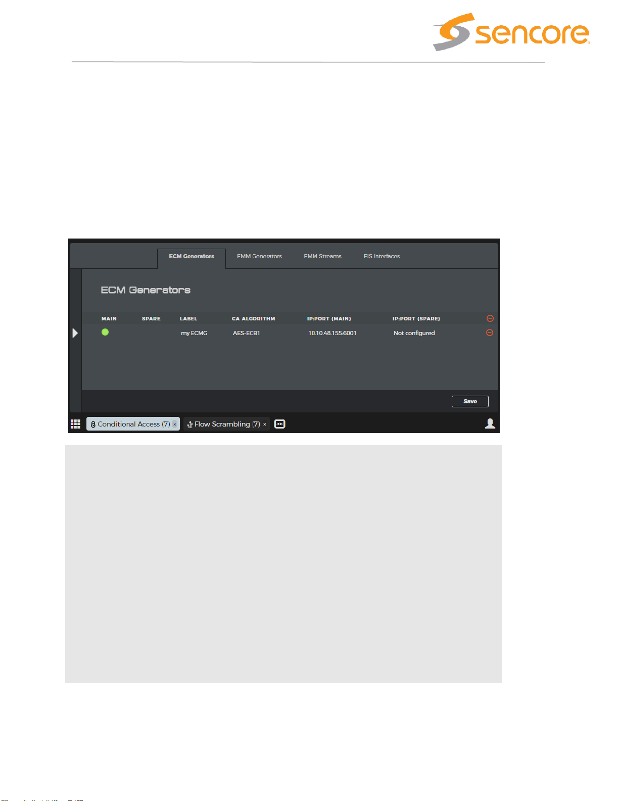
7 Conditional Access
The conditional access application has 4 tabs to configure; ECMG, EMMG, EMM streams and EIS. Add a new
configuration by expanding the left window pane with the arrow on the left-hand side. Edit a configured entry by closing
the “Add” pane and selecting an entry from the center window pane. The parameters available in the “Add” pane are also
available in the “Edit” pane.
7.1 ECM Generators
An ECMG (Entitlement Control Message Generator) is an external CA server that generates ECMs containing the control
word and entitlement information. Several ECMGs from different CA systems can be used at the same time, converting
the same control words to unique ECMs, by the use of DVB Simulcrypt.
Main
Status LED to indicate the state of the ECMG connection
Spare
Status LED for the spare ECMG connection.
main disconnects.
Label
A user defined label of the ECM generator.
CA
algorithm
The scrambling algorithm used to scramble services that use this ECMG.
IP:port
The TCP socket for each ECMG server.
7.1.1 Add new ECMG
Page 30

Page | 30
Label
A user defined label of the ECM generator.
CA algorithm
The scrambling algorithm used to scramble services that use this ECMG.
Channel ID
The ID of the ECM Simulcrypt channel.
CA system ID
The CA system ID allocated by DVB to identify copy protection systems.
Redundancy
mode
main (SCS1) and spare (SCS2). While main is in use, only a test connection
is established to the spare server. If the main servers disconnect, the spare
server will be used instead.
CA subsystem ID
Defines the Super CAS id in combination with the CA system ID, which
uniquely identifies the ECMG.
7.2 EMM Generators
An EMM generator can produce EMM streams that specifies the authorization levels for subscribers of the transport
streams. The EMM stream produced by the generator is described in the “EMM Streams” section.
Page 31

Page | 31
State
Green: Connected to server.
Red: Not connected to server.
Last
connected
IP
The IP address of the last EMMG server connected to the module.
Label
A user defined label of the ECM generator.
TCP port
The local TCP port of the module to which the server can connect.
Remote IPS
A list of server IP addresses that can connect to the module.
7.2.1 Add new EMM generator
Label
A user defined label of the EMM generator.
Page 32

Page | 32
Connection
Select connection type to the EMM server. TCP, UDP or TCP/UDP. With TCP/UDP
the initial setup uses TCP while data transfer is using UDP as defined by the
Simulcrypt standard.
TCP port
The local TCP port of the module to which the server can connect.
CA system
ID
The CA system ID allocated by DVB to identify copy protection systems.
CA
subsystem
ID
An identifier per connection in redundancy mode where there is multiple connection
to an EMMG with the same CA system ID.
Remote IP
Enter the EMM server’s IP address. Click the green “plus” button to add more
server IP addresses for redundancy.
7.3 EMM Streams
Label
A user defined label of the EMM generator.
UDP port
Local UDP port of the module used by the EMMG. Defined only if the EMMG is in
UDP or TCP/UDP mode.
RX bytes
Accumulated byte counter for received data.
7.3.1 Add a new EMM stream
Page 33

Page | 33
Label
A user defined label of the EMM generator.
EMM
Generator
Select a generator defined on the “EMM Generators” tab.
EMM stream
ID
An ID defined by the EMM server that identifies the stream.
Max bitrate
The maximum bitrate for the EMM stream.
CAT private
data
(Optional) User defined HEX string inserted in the private data section of the CAT
table.
PID
(Optional) The EMM packet identifier.
7.4 Flow Scrambling Application
The flow scrambling start page shows a list of all defined access control groups. An access control group is a group of
services that share the same ECMGs and Access Criteria.
To add new groups or services, expand the left window pane. To edit an existing group or service, select it in the center
pane, such that the edit pane appears on the right-hand side.
A special access control group named “Clear group” is predefined. No scrambling will be applied to services in this group
and no ECMs will be generated. This group can be useful during initial setup to test service routing before enabling
scrambling. When using EIS this group is a holding area for services that are not configured with scrambling.
Page 34

Page | 34
Label
A user defined label of the AC group. The label is only used by the GUI and will not
affect the stream.
Services
A group row displays the number of services in this group. A service row shows the
name of the service.
Source
The source slot number and multicast address per service.
CA
algorithm
The algorithm used from scrambling all services in the given group.
Number of
AC
Number of Access Criteria in each group.
Number of
ECMG
Number of ECM generators used in each group.
CP#
Crypto period counter that increments when the crypto period changes.
7.4.1 Create Access Control group
Expand the left window pane by pressing the arrow on the left-hand side. Highlight the input services that should be
included in the AC group and click "create AC group". To add services to an existing AC group, highlight the existing
group and click "Add to AC Group".
Page 35

Page | 35
Label
A user defined label of the AC group.
Mode
Select ECM or fixed-key scrambling.
ECMG
Select an ECMG from a list defined in the Conditional Access application.
Preferred
PID
(Optional) Define the ECM packet identifier.
CP duration
(Optional) Define minimum crypto period in seconds. Minimum value is 5 seconds.
AC type
Select the AC type, HEX or 32-bit INT.
Access
Criteria
An ID used by the CA system to manage access rights for the services in the AC
group.
Private Data
User defined HEX data added to the CA descriptor in the PSI.
7.4.2 Edit Access Control group
Click on a defined AC group to enable the edit pane on the right-hand side. All the parameters that was defined when the
AC group was created can be edited in this view.
Click the save button on the bottom of the centre window to apply changes.
7.4.3 Edit service
Expand the AC group in the overview window and click on a service. An edit pane on the right-hand side appears with
service specific settings.
Changes are applied after clicking the save button on the bottom of the centre window.
Page 36

Page | 36
Components
Select what type of PIDs to scramble.
Partial
Scrambling
Reduce the number of packets to scramble. No packets will be scrambled if set to
0%, but ECM and PSI are still generated.
PES header
in clear
If enabled, the PES header and a user defined number of packets the number of
packets in clear after the PES header must be configured. If the number of packets
is set to 0, then only the PES header will be sent in clear.
AC Group
Select an Access Control group to move the selected service(s) to that group.
Page 37

Page | 37
8 Encoders
Encoders are configurated using the Encoding applications in the dashboard. When an encoder has been configured and
enabled it will deliver a service to the backplane. This service can be picked up and sent out through an output interface.
8.1 Configuration Flow
Much of the Configuration of an Encoder is done through reusable Profiles. This way the same encoder configuration can
be applied to multiple services. If a Profile is altered, the change is automatically applied to all the services using the
Profile.
Profiles define parameters that are likely to be identical for many services. In contrast, service specific parameters are not
configured through Profiles but rather on an individual service level. Examples of service specific parameters are which
physical SDI input connector is used, service ID, language codes etc.
The starting point of building a service is to first define the necessary profiles, alternatively reuse existing Profiles.
Typically, and as a minimum, a video profile and an audio profile are required to build a service.
Typical Service Configuration Sequence:
Step 1 – Define one or more Video Profiles
Step 2 – Define one or more Audio Profiles
Step 3 – Define one or more Color Profiles
Step 4 – Define one or more VANC profiles
Step 5 - Configure Service using specific module and input connector, and the profiles defined
above.
Step 6 – Repeat Step5 to configure multiple services
8.2 Profiles
8.2.1 Encoder Video Profile
Page 38

Page | 38
The Encoder Video Profile defines the output characteristics of a video component. Encoder Video Profiles are defined
using the Encoder Video Profile App on the dashboard.
8.2.1.1 Encoder Video Profile - General
General
Label
Name of the Profile.
Latency
Latency mode. Use Normal for highest VQ.
8.2.1.2 Encoder Video Profile - Video
Video
Frame Rate
Frame rate in frames per second (fps). Note that HD 1080i and SD are 25fps or
29.97fps.
Page 39

Page | 39
Vertical
Resolution
Vertical resolution of encoded video.
Horizontal
Resolution
Horizontal resolution of encoded video.
Chroma
Sampling
Use 4:2:0 for applications transmitting to consumer equipment.
Bit Depth
Use 8-bit for AVC applications transmitting to consumer equipment.
Scanning
Mode
Progressive or Interlaced.
Aspect Ratio
Configures display aspect ratio of encoded video.
Fallback
Aspect Ratio
Configures display aspect ratio of encoded video when input is lost.
8.2.1.3 Encoder Video Profile – HEVC
Codec HEVC
Profile
Profile controls stream complexity. Available Profiles is restricted by Chroma
Sampling and Bit Depth above.
Level
Auto – Encoder selects appropriate Level based on resolution, bitrate etc.
Tier
Main or High Tier. The choice affects bitrate range allowed.
IDR
Frequency
Selects how frequently I frames are upgraded to IDR frames. Value of ‘0’ means no
IDR frames. Value of 4 means every 4th I frame is upgraded to IDR frame.
Bitrate
Elementary stream bitrate. Configurable range depends on resolution, tier, latency
mode etc.
GOP Mode
In Dynamic mode encoder alters GOP to optimize VQ.
GOP
Structure
Selects GOP composition. (Latency mode restricts options.)
Max B
Frames
Maximum number of successive B frames.
GOP Size
GOP size. Average distance between I/IDR frames.
Hierarchical
GOP
Enables hierarchical GOP. (Also referred to as Reference B frames.)
LDB
Low Delay B frames.
Page 40

Page | 40
8.2.1.4 Encoder Video Profile – AVC
Codec - AVC
Profile
Profile controls stream complexity. Available Profiles is restricted by Chroma
Sampling and Bit Depth above.
Level
Auto – Encoder selects appropriate Level based on resolution, bitrate etc.
CABAC
Selects entropy coding mode. CABAC off results in CAVLC being used. Less
computational complexity for the decoder.
IDR
Frequency
Selects how frequently I frames are upgraded to IDR frames. Value of ‘0’ means no
IDR frames. Value of 4 means every 4th I frame is upgraded to IDR frame.
Bitrate
Elementary stream bitrate. Configurable range depends on resolution, tier, latency
mode etc.
GOP Mode
In Dynamic mode encoder alters GOP to optimize VQ.
GOP
Structure
Selects GOP composition. (Latency mode restricts options.)
Max B
Frames
Maximum number of successive B frames.
GOP Size
GOP size. Average distance between I/IDR frames.
8.2.2 Audio Profile
The Encoder Audio Profile defines the output characteristics of an audio component. Encoder Audio Profiles are defined
using the Encoder Audio Profile App on the dashboard. Note that if a service consists of multiple audio tracks, multiple
audio profiles may be used for the same service.
Depending on audio codec, different parameters are available for configuration.
Page 41
Page | 41
8.2.2.1 Encoder Audio Profile – General
General
Label
Name of the Profile.
Codec
Codec
MPEG1, AAC LC, AAC HEv1, AAC HEv2, Dolby Digital, Dolby Digital Plus.
Channel
Mode
Stereo (2.0), 5.1 or 7.1 (Available options depending on codec)
Bit Rate
Bitrate (Available range depending on codec.)
Container
ADTS or LATM (for AAC codecs only.)
8.2.2.2 Encoder Audio Profile – Dolby
Codec parameters available for Dolby codecs.
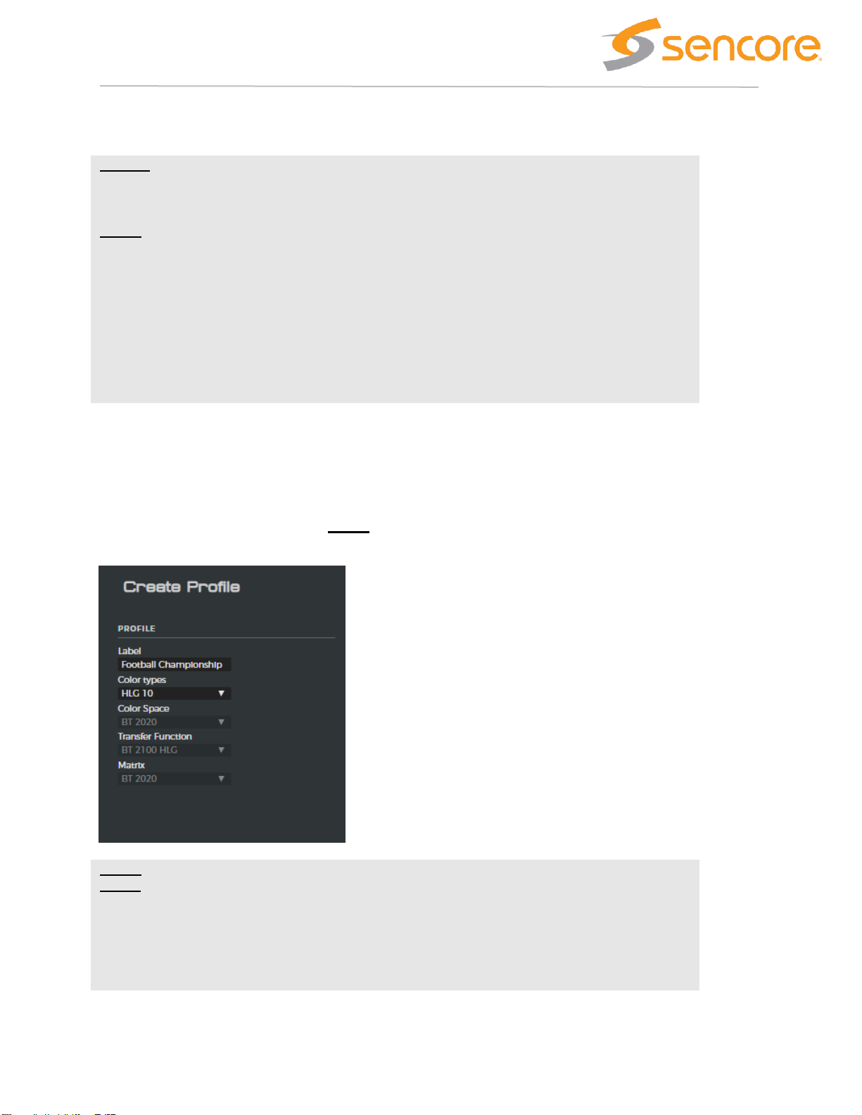
8.2.3 Encoder Colour Profile
The Encoder Colour Profile defines the output colour space, transfer function (SDR/HDR/WCG) characteristics of the
video component.
Create
profile
Label
Name of the Profile.
Colour types
Choose between predefined combinations (commonly used SDR and HDR modes)
or Manual.
Page 42

Page | 42
BT709, BT 2020 (WCG)
Transfer
Function
BT 2100 HLG (HDR), BT 2100 PQ (HDR), BT 2020 (SDR)
Matrix
BT709, BT 2020 (WCG)
8.2.4 Encoder VANC Profile
The Encoder VANC Profile defines how to process incoming VANC data.
8.2.4.1 Encoder VANC Profile – General
General
Label
Name of the Profile.
Profile Type
Two types of output data can be generated Digital Program Insertion (SCTE 104 to
SCTE 35 translation), or EN301775 Teletext.
8.2.4.2 Encoder VANC Profile – DPI
DPI
Heartbeat
Interval
Enables/disables heartbeat messages and defines interval between heartbeat
messages if enabled.
PTS Offset
Allows a PTS offset to be added to the output data.
Index
Configures a unique source index for the DPI data.
Page 43

Page | 43
8.2.4.3 Encoder VANC Profile – EN301775 TTX
EN301775
VANC
Standard
Configures format of the source VANC data. OP47 or SMPTE2031. All VANC lines
containing correctly formatted data will be processed.
Pages
Configures pages for Start, Subtitle, and Hearing-Impaired Subtitles together with
languages.
Line Filter
Allows captured input data to be filtered allowing unwanted data to be removed.
Page 44
Page | 44
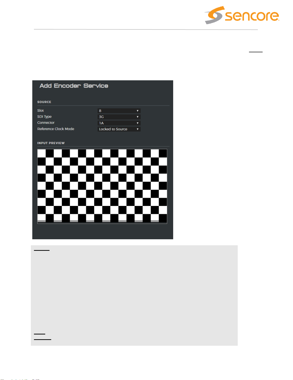
8.3 Encoder Services
Once audio and video profiles have defined, services can be configured. Service configuration links physical inputs (SDI
ports) to profiles. Services are defined using the Encoder Service App.
If there is a mismatch between input resolution (e.g. HD) and configured output resolution (e.g. SD) the encoder will try to
convert resolution. When resolution conversion is not possible, alarms will be raised.
Source
Slot
Selects the physical encoder where the service should run.
SDI Type
Selects the port mode. 12G SDI (used for UHD) or 3G SDI (used for FHD/ HD/SD)
or Quad Link used for quad link UHD (2SI or four quadrants).
Connector
Select between available connectors. Only 1A and 2A supports 12G SDI. For Quad
Link UHD, connectors 1ABCD or 2ABCD are combined.
Reference
Clock Mode
Select between Locked To Source (standard operation) or Video Alignment where
all services with the same group ID are aligned in terms of PTS/PCR.
Group ID
Used together with Video Alignment to create multiple aligned groups.
Input
Preview
Shows thumbnails of the video present on the input. If no input is available, the
thumbnail will show a checkered board.
Page 45

Page | 45
When the input source of a service has been selected, press save and continue to next step.
8.3.1.1 Encoder Service – Video
Source/Video
Enable/Disable
Enables/Disables service.
Profile
Selects which Encoder Video Profile to use.
Colour Profile
Selects which Encoder Colour profile to use.
Page 46

Page | 46
Colour Bars
Selects what the encoder should produce when no SDI input is present. Select
between Colour Bars and Black.
8.3.1.2 Encoder Service – Audio Passthrough
Note that when a passthrough component is generated, no Audio Profile is used since no audio encoding is performed.
Audio
Passthrough
Source
Codec
Dolby Digital, Dolby Digital Plus, Dolby E
Source
Channels
Selects data source in embedded audio.
Language
Define which language to signal for the audio component.
Audio Type
Select which audio type to signal for the audio component.
Lip Sync
Adjust
Allows lip sync adjustment to compensate for offsets in the input.
8.3.1.3 Encoder Service – Audio Encode
Audio
Source
Codec
PCM (uncompressed), Dolby E. In the case of Dolby E input, source will be
transcoded to the codec defined in the Profile used.
Source
Channel
Mode
Selects channel mode for source data.
Source
Channels
Selects data source in embedded audio.
Source
Channel
Mapping
Defines channel mapping/layout in source.
Profile
Selects which Encoder Audio Profile to use.
Language
Define which language to signal for the audio component.
Audio Type
Select which audio type to signal for the audio component.
Lip Sync
Adjust
Allows lip sync adjustment to compensate for offsets in the input.
8.3.1.4 Encoder Service – VANC Components
VANC
Components
Multiple VANC components can be added. Select VANC profiles to configure.
Page 47

Page | 47
8.3.1.5 Encoder Service – Service Parameters
Service
Service
Name
Configures service name in PSI/SI
Service
Provider
Configures Service Provider in PSI/SI.
Service ID
Configures Service ID in PSI/SI
PCR Interval
Configures PCR interval (average)
Audio # PID
Configures PID for each audio component
VANC # PID
Configures PID for each VANC component
Video PID
Configures PID for Video Component
PCR PID
Configures PID for PCR. Can be same as Video PID.
PMT PID
Configures PID for PMT for service.
Page 48

Page | 48
9 SDI over IP
The SDI input/output module is a converter module for running uncompressed video over IP. The board is fitted with 8
HD-BNC female connectors that can be individually programmed as input or output ports.
The configuration of the card is split into two application
• SDI Configuration – this is initial setup where the usage of the plugs is defined.
• SDI Input / Output – this is the setup of the SDI flows.
The SDI over IP module also support TICO lightweight compression. When used with compression then the cards are
unidirectional, and the SDI configuration applications will not be required for the initial setup.
The SDI HW currently supports the following products.
Hardware
Product
SIx100
SDI
SIx100
SDI TICO HD 2110 Encoder
SIx100
SDI TICO UHD Encoder
SIx100
SDI TICO UHD Decoder
SIx200
SDI Optical
SIx200
SDI Optical TICO HD 2110 Encoder
SIx200
SDI Optical TICO UHD Encoder
SIx200
SDI Optical TICO UHD Decoder
Page 49

Page | 49
9.1 SDI - Configuration application
The SDI Configuration application essentially determines the flow direction of the ports. This configurability is available for the
pure SDI products only.
The alternative modes are:
Input
The plug is an input type
Passthrough
This option is valid for even numbered ports where the previous port (n-1) is an
input port. Pass-through mode returns the content of port n-1.
Output
The plug is an output type.
Cloned
The plug is a copy of the output of plug n-1.
Page 50

Page | 50
9.2 SDI - Input / Output flow configuration
Once the port mode has been defined then the streams can be configured. Once the input ports are enabled the Thumbnail view
will display the detected input and the status on the right-hand side of the main list view will present basic input analysis info.
Enable
Enable the input stream analysis.
Note that disabling input ports will prevent routing of data to the backplane, but the
thumbnails will still be active.
Port
The input port ID
Mode
Reflects the settings done in the SDI Configuration application.
Label
A label for the stream.
Expected
format
Define the expected format of the input. If the input of the plug does not match the
setting then the card will raise an alarm. The source will not be blocked by an
unexpected input format.
Formats examples are supported.
* 1080i50
* 720p25
Source
Valid for output flows only. Drop-down dialog to choose the source from an input
card.
P. s: Only inputs to the unit of type RTP (As listed in the IP-IN application) will be
listed as valid sources for the SDI output plugs.
Page 51

Page | 51
9.3 IP-Gateway setup with SDI->IP flows
Once the SDI input is configured correctly the SDI feeds can be mapped out of the unit as IP flows. To do this, go to the
respective IP output location and select the RTP type sources. The ports configured as inputs will then be listed as valid sources.
Please refer to the IP output application description for a more detailed explanation on how to do this.
9.4 IP-Gateway setup with IP->SDI flows
In order to receive and SDI over IP flow to the SDI card the first step is to configure the IP input. Make sure the input is defined as
an RTP input, then the RTP input will be listed as a valid selection for the SDI output port.
9.4.1 Selecting the source
Once the input is defined in the IP input application it is possible to select the source in the SDI configuration app.
Open the SDI application…
And select the defined source.
Page 52

Page | 52
Once selected the service will be routed from the input card to the SDI where the IP->SDI conversion will take place.
Note the bitrate display in the flow view. In this example the SDI is taken from port 1 slot 14, sent out on the IP card in slot 4 port
D1, returned back to slot 4/D2 then sent back to the SDI card in slot 14 out on port 5….
9.4.2 Expected format
The expected format is an optional setting which will cause an alarm to be raised if the format of the selected source does not
match the expected format. Note that the output will not be affected by this setting, the alarm generation only.
Page 53

Page | 53
9.4.3 Status
The Status presented is extracted from the SDI content of the IP source.
The Port status bracket indicates how many flows currently selected. In this
case (1)
The port actually selected is shown next to the cog-wheel and is in this case
“SDI 5”.
9.4.4 Status of multiple ports
Multi-select is supported in the SDI application. This provides an easy overview of the status for all ports. In this case 6 ports are
selected in the main flow view…
Page 54

Page | 54
Page 55

Page | 55
9.5 SDI TICO UHD (2022-6)
The TICO UHD encoder/Decoder is a unidirectional card. I.e. the flow direction is defined by the software image loaded to the
card. Hence the flow direction we find in the SDI product has not meaning here.
The UHD encoder encapsulates the SDI inti IP according to 2022-6. I.e. the entire SDI is placed into one IP flow.
The UHD encoder/decoder will automatically TICO encode the signal if a 12G source is detected. If not, the card will operate as if
it was an SDI card. The 12G sources must be connected to port 1 and 5 only. For Quad signals 4 ports are used per service.
The UHD encoder and decoder applications are separate apps listed on the start page.
As for the SDI products the flows can be labeled and configured with an expected format qualifier. If the content does not match
the expected format an alarm will be raised.
9.5.1 UHD Encoder
9.5.2 UHD Decoder
Page 56

Page | 56
The status of the decoder indicates if the source is TICO encoded and with which profile.
Page 57

Page | 57
9.6 TICO HD Encoder (2110)
The TICO HD encoder is quite different from the UHD by the fact that the HD signal is encapsulated into IP according to SMPTE
2110. This means each part of the SDI (the essences) is encapsulated into separate IP flows. This makes the configuration
process of the IP flows different from the 2022-6 case.
9.7 Stream Labels
In a ST2110 configuration all the SDI components will be transferred as unique flows. The label will be configured for the SDI
input, just like the standard SDI in/out cards. This input label will then be mapped to the individual flows according to the type of
data.
Example: Label the stream NRK. Then the label of the components will be
• NRK.Video
• NRK.Audio.1&2, NRK.Audio.3&4 ...etc.
• NRK.Anc
9.7.1 SDI input status
Once the HD signal is connected to the SDI input the card will perform basic analysis of the input signal. This is helpful to see
what video format is present, and also where the audio is located in the SDI source.
9.7.2 HD TICO Configuration
To configure the TICO encoder, select the Edit tab above the thumbnail.
Page 58

Page | 58
If the TICO license is not installed the card can still be used for 2110 encapsulation, but the actual TICO encoding will not be
available. With the TICO license the TICO compression can be enabled.
9.7.3 The TICO encoder configuration
• Supported Input formats, 1080i or 720p50
• Uses a TICO Profile 2 encoder
• Compression ratio, default 4:1, configurable [2:1, 4:1, 5:1].
The bitrate will be auto-adapted by the system based on the format of the source.
• Encoding characteristics can be optimized for PSNR or Visual.
• RTP encapsulation according SMPTE RDD35 35:2016
9.7.4 Audio configuration
The audio configuration is per audio stream. Each audio stream will be mapped to separate RTP flows where the following
configuration must be set.
Page 59

Page | 59
• Select source channel Source:
o Stereo channels from
(1&2) -> (15&16)
o 5.1 channels from
(1->6), (3->8) and (9->14)
• Audio packet repetition rate
o Packet rate: (1 ms or 125 us).
▪ SMPTE 2110 Conformance Level B requires support for both repetition rates. Level A = 1ms.
• Output encapsulation format:
o AES67(SMPTE 2110-30):
▪ Valid audio sources: Uncompressed only. AES67/PCM
▪ Stereo or 5.1
o Compressed (SMPTE 2110-31):
▪ Valid for both compressed AND uncompressed input. Dolby-E, AES67/PCM
▪ Stereo only….
9.7.5 2110-40 Ancillary data
No parameters to configure. The ancillary data is by default included in the encoder. Stopping this essence is off course
possible to do when mapping the essences to the IP destination addresses on the IP output card.
Page 60

Page | 60
10 ASI
The ASI module uses the same hardware as the SDI over IP products. As for the uncompressed SDI over IP product the ASI
card has a bi-directional capability where the port directions are configurable.
The configuration of the card is split into three applications
• ASI Configuration – this is initial setup where the port directions are defined.
• ASI Input – this is the configuration of the ASI input streams
• ASI output – this is the setup of the ASI output streams.
10.1 ASI - Configuration application
The ASI Configuration App is located as part of the Configuration apps on the main desktop view.
The ASI Configuration application must be used to configure the flow direction of the ports. Any port listed as input will be
available in the ASI input application, and similarly the once set to output will be available in the ASI output application.
Page 61

Page | 61
The alternative modes are simply Input or Output.
10.2 ASI – Input flow configuration
The configuration of an ASI input card is simply to enable / disable a port and configure the analysis mode to be MPEG or DVB.
Once a port is enabled the system will start to analyze the input PSI accordingly.
10.3 ASI - Output flow configuration
The configuration of the ASI output is essentially to add define the attributes of the ASI port, and then to add services to the port
itself. Please refer to the IP output application description for an explanation on how to add content to an output.
10.4 ASI output port settings
For each ASI output port the following parameters must be set.
Page 62

Page | 62
Enabled
The enable checkbox lets the operator easily disable an output. The stream is still
defined in the system, but the stream output is muted.
Label
The label can be added during definition, and changed directly from the list view.
TS ID
The MPEG transport stream ID which will be signaled in PAT.
Bitrate
If enabled the output transport is set to a fixed CBR rate. In Burst mode the output
may be configured all the way up to 213 Mbps, while in Spread byte mode it is limited
to 72Mbps.
Packet
size
188 or 204
Byte
mode
The ASI output supports both Spread byte mode and or Burst byte mode.
10.5 ASI output status
The ASI status pane on the output configuration page shows both the Effective and total transport stream bitrate. The Total
bitrates equals the effective bitrate with the additional NULL-packets.
Page 63

Page | 63
11 Decoders
Decoders are configured using the Decoding applications in the dashboard. When a decoder has been configured and
enabled it will deliver decoded video and audio through the SDI output connectors. The input to the decoder comes from
one of the input interfaces in the chassis and is delivered to the decoder over the backplane.
11.1 Configuration Flow
Parts of the Configuration of a Decoder is done through reusable Profiles. This way the same decoder configuration can
be applied to multiple services. If a Profile is altered, the change is automatically applied to all the services using the
Profile.
Profiles define parameters that are likely to be identical for many services. In contrast, service specific parameters are not
configured through Profiles but rather on an individual service level. Examples of service specific parameters are which
physical SDI output connector is used, audio output format etc.
The starting point of building a service is to first define the necessary profiles, alternatively reuse existing Profiles.
Typical Service Configuration Sequence:
Step 1 – Define one or more Video Profiles
Step 2 - Select which input service to decode
Step 3 - Configure Service using specific module and output connector, and a profile defined
above.
Step 4 – Repeat from Step2 to configure multiple services
11.2 Profiles
11.2.1 Decoder Video Profile
The Decoder Video Profile defines the output characteristics of a video component.
Page 64

Page | 64
11.2.1.1 Decoder Video Profile - General
General
Label
Name of the Profile.
Latency
Latency mode. This should match the latency mode of the Encoder. For broadcast
applications use Normal.
11.2.1.2 Decoder Video Profile - Video
Video
Frame Rate
Frame rate in frames per second (fps). Note that HD 1080i and SD are 25fps or
29.97fps.
Vertical
Resolution
Vertical resolution of encoded video.
Horizontal
Resolution
Horizontal resolution of encoded video.
Bit Depth
Use 8-bit for AVC applications transmitting to consumer equipment.
Page 65

Page | 65
Scanning
Mode
Progressive or Interlaced.
Aspect Ratio
Configures display aspect ratio of encoded video.
Fallback
Aspect Ratio
Configures display aspect ratio of encoded video when input is lost.
11.3 Add Decoder Services
Once video profiles have been defined, services can be configured. Service configuration links service inputs to decoder
profiles and physical outputs. Services are defined using the Decoder Service App.
11.3.1 Input Service Selection
The source view lists all services available from all active input interfaces in the chassis.
TODO: Add picture with service list.
11.3.2 Decoder Selection
If there is a mismatch between input resolution (e.g. HD) and configured output resolution (e.g. SD) the decoder will raise
an alarm.
Page 66

Page | 66
Output
Enabled
Enable/Disable decoder.
Slot
Selects the physical encoder where the service should run.
SDI Type
Selects the port mode. For UHD output use 12G SDI, Quad Link Square Division or
Quad Link Two Sample Interleaved. For FHD/ HD/SD use 3G SDI
Connector
Select between available connectors. Only 1A and 2A supports 12G SDI. For Quad
Link UHD, connectors 1ABCD or 2ABCD are combined.
Reference
Clock Mode
Select between:
• Locked To Source (standard operation
• Genlocked (Black burst reference on switch)
• Video Alignment where all services with the same group ID are aligned in
terms of PTS/PCR.
Group ID
Used together with Video Alignment to create multiple aligned groups.
Page 67

Page | 67
Genlock
offset
Used together with Genlock mode to allow alignment adjustment in pixels.
Input
Preview
Shows thumbnails of the video present on the input. If no input is available, the
thumbnail will show a checkered board.
When the input source of a service has been selected, press save and continue to next step.
11.3.2.1 Audio
Multiple audio components can be added by pressing the ‘+’ icon. The input component filter allows automatic
filtering/selection between multiple audio components based on PSI/SI data.
Input Component
Component Type
Selects component based on type (codec)
PID
Selects component based on PID.
Language
Selects component based on Language ISO.
Audio data output is put into SDI embedded audio.
Embedded Audio
Channel Mode
Output decoded audio as Stereo or 5.1|
Destination
Selects data in embedded audio.
Level Adjustment
Allows audio level adjust after decode.
Page 68

Page | 68
12 S2X Output Application
To launch a S2X output application, locate the “S2X Output (Slot Number)” application in the “Output” row on the
desktop and click the icon.
The start page of the output application lists the defined outputs.
Enabled
The enable checkbox lets the operator easily disable an output. The stream is still
defined in the system, but the data stream is stopped and the RF output is muted.
Modulator
The physical RF port where the stream is being transmitted.
Label
The label can be added during definition, and changed directly from the list view.
Alarms
Each output will get a red balloon in this column if an alarm is raised that affects this
output.
Frequency
Carrier frequency of the RF signal.
Symbol
Rate
Symbol rate of the modulated signal.
Source
The internal source of each service in the output mux.
Content
This column will display the service id + name (if available) for MPEG/DVB content.
Red Circle
Action button to remove streams from the output.
The configuration process starts by creating three types of templates that can be used many times over to configure
modulators quickly. The three templates include:
1. Port profiles define RF parameters and modulator settings to make it possible to define settings for say Hotbird
transponder 1. A second template can be built to define Hotbird transponder 2 etc. The port profiles make it easy
to predefine parameter sets, minimising the chance of human error and greatly increasing the speed of set-up.
2. Pre-correction parameter settings for amplitude linearity and group delay. These settings are normally
transponder specific and mainly defined by the satellite specific IMUX / OMUX filters.
3. Carrier ID profiles can be used to predefine operator information and apply the same parameter set to both RF
outputs.
Page 69

Page | 69
12.1 Port profiles
The first step in configuring a modulator output is to define a port profile. Select the port profile tab and expand the left
pane with the arrow button.
A port profile can be defined without being applied to a modulator or it can be applied to both modulators at the same
time. If the configuration of a profile in use is changed, the change propagates to the affected modulators immediately. A
port profile can link to Carrier ID and precorrection profiles completing the full RF and modulation configuration.
12.2 Carrier ID
DVB Carrier ID is defined as profiles in the Carrier Identification tab to be able to apply and change one configuration for
both outputs. Multiple profiles can be defined for fast and easy reconfiguration.
Page 70

Page | 70
12.3 Precorrection
Add a precorrection profile by expanding the left window pane and select either linear gain or linear group delay. The
distortion specification is defined as coordinates in the edit pane on the right-hand side. The entered coordinates are
visualized in a graph for verification. Both types of precorrection are symmetric filters, hence the channel response only
needs to be defined from the center frequency to the highest frequency component. The channel response can be
defined independent of the actual bandwidth in use.
12.4 Adding services to a mux
To add a new output, expand the left pane in the Modulator Settings tab and select the sources to add. Select an output
mux and click the add button at the bottom of the pane. Selecting a service row instead of a TS row enables the “Replace
Content” button that can remove an existing service and add the new service in one operation. To discard non-saved
changes, close the application.
12.4.1 Supported mapping modes
The action button which maps the selected source material to the output will change depending on the type of data to be
mapped, and depending on the destination of the content.
The system offers the following mapping modes.
Source
Action
Mapping action
Service
Add to existing
output
With a service to transport mapping, select destination modulator row
and use the Add action button, then the service will be added to the
selected output transport stream.
Page 71

Page | 71
Service
Replace a
service
Use the replace service to replace the destination service with the
selected source service.
TS
Create an
output
When a TS source is added the entire MPEG/DVB transport stream
will be mapped, including NULL packet.
Autofirst
Create/add or
replace
In some system configurations the input is not present at the time of
configuration of the system. When doing an auto-first mapping the
output service ID is by default set to 1 by the backend software. The
source service selected is any service detected on the source. If the
source transport contains multiple services any of the services, but
only one, will be selected. This value can be overwritten by changing
the outgoing service ID in the edit output configuration dialog.
Source
Action
Mapping action
Service
Add to existing
output
With a service to transport mapping, select destination modulator row
and use the Add action button, then the service will be added to the
selected output transport stream.
Service
Replace a
service
Use the replace service to replace the destination service with the
selected source service.
TS
Create an
output
When a TS source is added the entire MPEG/DVB transport stream
will be mapped, including NULL packet.
Autofirst
Create/add or
replace
In some system configurations the input is not present at the time of
configuration of the system. When doing an auto-first mapping the
output service ID is by default set to 1 by the backend software. The
source service selected is any service detected on the source. If the
source transport contains multiple services any of the services, but
only one, will be selected. This value can be overwritten by changing
the outgoing service ID in the edit output configuration dialog.
12.5 Changing output attributes
To edit an output, click the object and the edit dialog will appear on the right-hand side. Use multiselect to edit both
modulator outputs simultaneously.
Page 72

Page | 72
PORT SETTINGS
Enabled
Enabled/disable RF output.
CW Carrier Test
Mode
Enable CW test mode to disabled modulation and only output a single carrier
wave.
RF Source
Status showing the active source of the RF output. The status can be Main,
Backup or Mute.
Front Switch
Status of the front switch position. Switch position can be Auto, Main, Backup
or Mute.
Software Switch
Dropdown to select RF source. Only applicable if Front Switch is set to Auto. If
Software Switch is set to auto the backup can be switched in if the backup is
present and the “failure index” is above 100, SEE REDUNDANCY
CHAPTER.
Backup Present
Threshold
Define RF level threshold for backup present detection.
Backup
Backup present status. Status is Present if measured RF level of backup is
higher than configured threshold.
Backup Port
Level
Status of current measured backup RF level.
Page 73

Page | 73
Switchback
Threshold
Set failure index threshold of when the RF output shall switch from Backup to
Main.
Reference Output
10MHz
Enable embedded 10MHz output that is synchronous to the modulated RF
output.
DC Output 24V
Enable embedded 24V DC output.
PORT PROFILE
Port Profile
Select a predefined port profile from the dropdown. The profiles are defined in
the Port profiles tab and includes all modulation parameters.
Profile overrides
Selected parameters from selected Port Profile can be override by enabling
the checkbox and changing the parameter value.
TS bitrate for
config
Calculated TS bitrate for the current configuration. This status is updated
immediately when configuration is changed without the need to save the
configuration.
BITRATE
STATUS
TS bitrate
Current TS bitrate, including null packets.
Effective bitrate
Current measured effective bitrate, not including null packets.
TRANSPORT
SETTINGS
TS ID
Define the TS ID
Scrambling
enabled
Enable embedded scrambling on the TS.
Scrambling
Method
Select scrambling method: Raw Fixed Key, BISSv1 or BISSv2.
Selecting a service object will produce the following edit dialog.
Service ID
Optional. Use this to override the output service ID.
Page 74

Page | 74
Service Name
Optional. Use this to override the output service ID.
Scrambled
Components
Optional. Use to select what PID types to scramble.
Service Priority
Define the value to increase the “error index” when this service has a critical
alarm. Set a value less than 100 to prevent switch to backup when this service
has issues.
Page 75

Sencore Inc.
3200 Sencore Drive
Sioux Falls, SD 57107 USA
www.sencore.com
Copyright © 2018 Sencore Inc. 1.605.978.4600
 Loading...