

Page 1

DMG 3200
MODULAR
HI-DENSITY
HOT-SWAP
Status
Control
SWITCH
IPIO Control
Sync In
Data A Data B
DMG 3200
DATA A
DATA BCONTROL
DMG 3200/3100/3000
Digital Media Gateway
User Manual
8037A www.sencore.com | 1.605.978.4600 Revision 2.0
December 2014
Page 2

DMG 3200/3100/3000 – User Manual
Copyright
© 2014 Sencore, Inc. All rights reserved.
3200 Sencore Drive, Sioux Falls, SD USA
www.sencore.com
This publication contains confidential, proprietary, and trade secret information. No part of this document
may be copied, photocopied, reproduced, translated, or reduced to any machine-readable or electronic
format without prior written permission from Sencore. Information in this document is subject to change
without notice and Sencore Inc. assumes no responsibility or liability for any errors or inaccuracies.
Sencore, Sencore Inc, and the Sencore logo are trademarks or registered trademarks in the United States
and other countries. All other products or services mentioned in this document are identified by the
trademarks, service marks, or product names as designated by the companies who market those products.
Inquiries should be made directly to those companies. This document may also have links to third-party web
pages that are beyond the control of Sencore. The presence of such links does not imply that Sencore
endorses or recommends the content on those pages. Sencore acknowledges the use of third-party open
source software and licenses in some Sencore products. This freely available source code can be obtained
by contacting Sencore Inc.
About Sencore
Sencore is an engineering leader in the development of high-quality signal transmission solutions for the
broadcast, cable, satellite, IPTV, and telecommunications markets. The company's world-class portfolio
includes video delivery products, system monitoring and analysis solutions, and test and measurement
equipment, all designed to support system interoperability and backed by best-in-class customer support.
Sencore products meet the rapidly changing needs of modern media by ensuring the efficient delivery of
high-quality video from the source to the home. More information about Sencore is available at the
company’s website, www.sencore.com
All trademarks and registered trademarks mentioned herein are the property of their respective owners.
.
Page 2 (306)
Page 3

Date
Version
Description
Author
01/09/12
1.0
Initial Release
ACD
12/01/14
2.0
DMG 3200 Release
ACD
Revision History
DMG 3200/3100/3000 – User Manual
Page 3 (306)
Page 4

DMG 3200/3100/3000 – User Manual
FCC Class A Information
The DMG 3200/3100/3000 has been tested and found to comply with the limits for a
Class A digital device, pursuant to Part 15 of the FCC Rules. T hese limits are designed
to provide reasonable protection against harmful interference when the equipment is
operated in a commercial environment. This equipment generates, uses, and can radiate
radio frequency energy and, if not installed and used in accordance with the instructions,
may cause harmful interference to radio communications. Operation of this equipment in
a residential area is likely to cause harmful interference in which case the user will be
required to correct the interference at his or her own expense.
Shielded cables must be used with this unit to ensure compliance with the Class A FCC
limits.
Warning: Changes or modifications to this unit not expressly approved by the
party responsible for compliance could void the user’s authority to operate the
equipment.
Page 4 (306)
Page 5

DMG 3200/3100/3000 – User Manual
WARNING
PLEASE OBSERVE THESE SAFETY PRECAUTIONS
There is always a danger present when using electronic
equipment.
Unexpected high voltages can be present at unusual locations in defective equipment
and signal distribution systems. Become familiar with the equipment that you are
working with and observe the following safety precautions.
• Every precaution has been taken in the design of your 3200/3100/3000 to ensure
that it is as safe as possible. However, safe operation depends on you the
operator.
• Always be sure your equipment is in good working order. Ensure that all points of
connection are secure to the chassis and that protective covers are in place and
secured with fasteners.
• Never work alone when working in hazardous conditions. Always have another
person close by in case of an accident.
• Always refer to the manual for safe operat ion. If you have a question about the
application or operation call SENCORE for assistance.
• Never allow your equipment to be exposed to water or high moisture
environments. If exposed to a liquid, remove power safely (at the breaker) and
send your equipment to be serviced by a qualified technician.
Page 5 (306)
Page 6

DMG 3200/3100/3000 – User Manual
1) Documentation CD
2) Quick Install Guide
3) AC Power Cable
Package Contents
The following is a list of the items that are included along with the DMG 3200/3100/3000:
1. User Manual
2. Quick Install Guide
3. AC Power Cable (2 for DMG 3200 and 3000, 1 for DMG 3100)
Note: If any option cables were ordered with the DMG 3200/3100/3000, they will be
included in the box as well.
If any of these items were omitted from the packaging of the DMG 3200/3100/3000
please call 1-800-SENCORE to obtain a replacement.
Page 6 (306)
Page 7

DMG 3200/3100/3000 – User Manual
Table of Contents
1 Introduction ................................................................................................... 12
2 Installation and Safet y .................................................................................. 13
2.1 Installation and Safety ...................................................................................................... 13
2.1.1 The 4RU Chassis ......................................................................................................... 13
2.1.2 1RU Chassis DMG 3200.............................................................................................. 15
2.1.3 Safety Considerations .................................................................................................. 16
2.1.4 Installation .................................................................................................................... 17
2.1.5 Information on Disposal ............................................................................................... 20
2.1.6 Laser Safety ................................................................................................................. 20
3 Physical Module Configuration ................................................................... 22
3.1 Connecting switch modules ............................................................................................. 22
3.1.1 Switch module with MMI .............................................................................................. 22
3.1.2 Switch module with MMI and IP IO .............................................................................. 22
3.2 MMI MicroSD Installation ................................................................................................. 23
3.3 Connecting Input Signals ................................................................................................. 23
3.3.1 IP Input ......................................................................................................................... 23
3.3.2 ASI Input ...................................................................................................................... 24
3.3.3 DVB-S/S2 Input ............................................................................................................ 24
3.3.4 COFDM Input ............................................................................................................... 24
3.3.5 DVB-T/T2 Input ............................................................................................................ 25
3.3.6 QAM A/C Input ............................................................................................................. 25
3.3.7 8VSB Input ................................................................................................................... 25
3.3.8 QAM-B Input ................................................................................................................ 25
3.3.9 SDI Encoder ................................................................................................................. 25
3.3.10 Analog Encoder ........................................................................................................... 27
3.4 Connecting Output Signals .............................................................................................. 28
3.4.1 IP Output ...................................................................................................................... 28
3.4.2 ASI Output ................................................................................................................... 28
3.4.3 QAM Output ................................................................................................................. 28
3.4.4 COFDM Cable Output.................................................................................................. 29
3.4.5 DVB-T/T2 Output ......................................................................................................... 29
3.4.6 DVB-S/S2 Output ......................................................................................................... 29
4 Administrative Settings Configuration ....................................................... 29
4.1 Accessing the Web Interface ........................................................................................... 29
4.1.1 Assigning an IP Address .............................................................................................. 33
4.1.2 IPv6 Address Support .................................................................................................. 35
4.1.3 Management over IP-Data Port and VLANs ................................................................ 37
4.1.4 Broadcast Firewall ....................................................................................................... 38
4.1.5 Internal Time Clock Setting / Network Time Protocol (NTP) Server ............................ 38
4.1.6 Automatic Daylight Saving ........................................................................................... 39
4.1.7 Password Protection in the GUI ................................................................................... 40
4.1.8 Changing the Password for the GUI ............................................................................ 40
4.1.9 Optional Languages ..................................................................................................... 41
4.2 Configuration of Clock reference module ......................................................................... 41
4.3 Licensing .......................................................................................................................... 42
4.3.1 Ordering a License File ................................................................................................ 43
4.3.2 Installing a License File................................................................................................ 43
Page 7 (306)
Page 8

DMG 3200/3100/3000 – User Manual
4.3.3 Demo Licenses ............................................................................................................ 44
5 Input Configuration ...................................................................................... 44
5.1 The Inputs Node ............................................................................................................... 44
5.2 Input Analysis ................................................................................................................... 45
5.2.1 Input Port Analysis ....................................................................................................... 46
5.2.2 Input Service Filtering and Analysis ............................................................................. 47
5.2.3 Input PID Analysis ........................................................................................................ 48
5.3 Manual PSI ....................................................................................................................... 50
5.3.1 MPTS Support ............................................................................................................. 51
5.3.2 PSI Modifications of input services .............................................................................. 52
5.3.3 Defining a component type for an incoming PID. ........................................................ 52
5.3.4 Changing the language descriptor of an incoming audio ............................................ 53
5.3.5 Edit options on existing manual PSI ............................................................................ 54
5.4 Input Modules ................................................................................................................... 55
5.4.1 DVB-S/S2 Input ............................................................................................................ 55
5.4.2 ASI Input ...................................................................................................................... 60
5.4.3 QAM/DVB-C Input ........................................................................................................ 63
5.4.4 COFDM / DVB-T Input ................................................................................................. 67
5.4.5 IP Input ......................................................................................................................... 72
5.4.6 Seamless IP Input ........................................................................................................ 81
5.4.7 Dual IP Input ................................................................................................................ 84
5.4.8 8VSB Input ................................................................................................................... 85
5.4.9 QAM-B Input ................................................................................................................ 86
5.4.10 DVB-T2 Input ............................................................................................................... 88
6 Conditional Access Configuration .............................................................. 92
6.1 Descrambling – Common Interface Module ..................................................................... 94
6.1.1 Descrambling a Service ............................................................................................... 94
6.1.2 Transporting a Descrambled Service to Multiple Output Modules/Ports ..................... 94
6.1.3 CAM Configuration ....................................................................................................... 94
6.1.4 Alt CAM Mode .............................................................................................................. 96
6.1.5 CAM Interface .............................................................................................................. 97
6.1.6 Navigation .................................................................................................................... 97
6.1.6.1 Multiple Users and CAM access .................................................................................. 98
6.1.7 Error Handling .............................................................................................................. 99
6.2 Bulk Descrambling ......................................................................................................... 100
6.2.1 Verimatrix Configuration ............................................................................................ 101
6.2.2 BISS Scrambling and Descrambling .......................................................................... 103
6.2.3 SIM bulk Descrambler................................................................................................ 105
6.3 Scrambling ..................................................................................................................... 109
6.3.1 Scrambler Module Configuration ............................................................................... 110
7 Digital Output Configuration ...................................................................... 120
7.1 Input Stream Selection ................................................................................................... 121
7.2 Auto Service Modes ....................................................................................................... 123
7.2.1 Configuring an output with Auto All Services ............................................................. 123
7.3 Transport Stream Generation ........................................................................................ 125
7.3.1 Transport Settings ...................................................................................................... 129
7.3.2 Port Settings .............................................................................................................. 131
7.3.3 EMM ........................................................................................................................... 131
7.3.4 HbbTV Apps ............................................................................................................... 132
7.3.5 PSI ............................................................................................................................. 132
Page 8 (306)
Page 9

DMG 3200/3100/3000 – User Manual
7.3.6 EPG............................................................................................................................ 134
7.3.7 Service ....................................................................................................................... 134
7.3.8 Components ............................................................................................................... 137
7.3.9 Scrambling ................................................................................................................. 143
7.4 Output Port Settings ....................................................................................................... 145
7.4.1 IP Output module ....................................................................................................... 145
7.4.2 Cloned IP Output Module .......................................................................................... 147
7.4.3 Dual IP Output ........................................................................................................... 150
7.4.4 ASI Output Module ..................................................................................................... 151
7.4.5 QAM Output Module .................................................................................................. 153
7.4.6 COFDM Output Module ............................................................................................. 155
7.4.7 DVB-S/S2 Output Module .......................................................................................... 157
7.4.8 DVB-T2 Output Module.............................................................................................. 160
7.5 Output Options ............................................................................................................... 161
7.5.1 Enable/Disable Services in Outgoing MPTS. ............................................................ 161
7.5.2 Virtual MPTS Output .................................................................................................. 161
7.5.3 MPTS Transparent Mode .......................................................................................... 162
7.5.4 MPTS Semi-Transparent Mode ................................................................................. 163
7.5.5 Service Filtering in Semi-Transparent Mode ............................................................. 165
7.5.6 Service Prior it y Se lec t io n ........................................................................................... 166
7.6 PSI/PSIP Configuration .................................................................................................. 168
7.6.1 Editing the PSI Network configuration ....................................................................... 170
7.6.2 Editing the PSI Default Values ................................................................................... 171
7.6.3 Editing the Logical Chanel Descriptor (NIT) .............................................................. 172
7.6.4 Editing the BAT table ................................................................................................. 174
7.6.5 Editing the TOT Local Time Offset Descriptor ........................................................... 174
7.6.6 PSI Synchronization ................................................................................................... 175
7.6.7 Inserting Generic Descriptors .................................................................................... 177
7.6.8 Inserting DVP STP ..................................................................................................... 179
7.6.9 PSI Generation Setup ................................................................................................ 180
7.6.10 DVB ATSC, ATSC DVB Con versi on ................................................................ 181
7.6.11 SI Domain Support ..................................................................................................... 182
8 Encoder and Transcoder Configuration ................................................... 183
8.1 General information ........................................................................................................ 183
8.2 Encoder Configuration ................................................................................................... 184
8.2.1 Source Parameters .................................................................................................... 186
8.2.2 Pre Processing Parameters ....................................................................................... 187
8.2.3 Audio Parameters ...................................................................................................... 188
8.2.4 VBI/VANC Parameters............................................................................................... 190
8.2.5 Service Parameters ................................................................................................... 193
8.2.6 Analog Encoder Configuration ................................................................................... 195
8.2.7 Logo Insertion ............................................................................................................ 196
8.3 Transcoder Configuration ............................................................................................... 198
8.3.1 Source Parameters .................................................................................................... 199
8.3.2 Pre-Processing Parameters ....................................................................................... 200
8.3.3 Audio Parameters ...................................................................................................... 202
8.3.4 Configuring a service for transcoding. ....................................................................... 204
8.4 Common Encoder/Transcoder Configuration ................................................................ 206
8.4.1 Video Parameters ...................................................................................................... 206
8.4.2 Video Extended Parameters ...................................................................................... 208
Page 9 (306)
Page 10

DMG 3200/3100/3000 – User Manual
8.4.3 MPEG-2 Parameters .................................................................................................. 210
8.4.4 H.264 Parameters ...................................................................................................... 210
8.5 Universal Broadcast Transcoder Configuration ............................................................. 212
8.5.1 Source Parameters .................................................................................................... 214
8.5.2 Pre-Processing Parameters ....................................................................................... 216
8.5.3 Video Parameters ...................................................................................................... 217
8.5.4 Video Extended Parameters ...................................................................................... 218
8.5.5 MPEG-2 Parameters .................................................................................................. 220
8.5.6 H.264 Parameters ...................................................................................................... 221
8.5.7 Audio Parameters ...................................................................................................... 221
8.5.8 Subtitling Parameters ................................................................................................. 223
8.5.9 Logo Insertion ............................................................................................................ 224
8.6 Universal Multiscreen Transcoder Configuration ........................................................... 225
8.6.1 Video Parameters ...................................................................................................... 227
8.6.2 Audio Parameters ...................................................................................................... 228
8.6.3 Profile Parameters ..................................................................................................... 230
8.6.4 Configuration Copying ............................................................................................... 233
8.7 Statistical Multiplexing .................................................................................................... 235
8.7.1 Modules Supported .................................................................................................... 235
8.7.2 Statmux group configuration ...................................................................................... 235
8.7.3 StatMux service output configuration ......................................................................... 240
8.8 Adding Logo Images ...................................................................................................... 241
8.8.1 Uploading Logo to the MMI ........................................................................................ 241
9 Digital Processing Modules ....................................................................... 242
9.1 Audio Leveling Module ................................................................................................... 242
9.2 Electronic Program Guide (EPG) ................................................................................... 244
9.2.1 EPG Status ................................................................................................................ 244
9.2.2 Setting up EPG .......................................................................................................... 246
9.3 Adding EPG information to a Transport Stream ............................................................ 249
9.3.1 Playout Rate, Playout Limit, and Priority ................................................................... 250
9.3.2 EIT Source Setup ....................................................................................................... 252
10 Redundancy Support .............................................................................. 252
10.1 Input Redundancy .......................................................................................................... 252
10.1.1 Configuring Service-based Input Redundancy .......................................................... 254
10.1.2 Configuring Port-based Input Redundancy ............................................................... 254
10.1.3 Alarms that cause Switching ...................................................................................... 255
10.1.4 Input Redundancy and the MMI ................................................................................. 256
10.1.5 Seamless Input Redundancy ..................................................................................... 257
10.2 Internal Redundancy ...................................................................................................... 259
10.2.1 Dual backplane configuration .................................................................................... 259
10.2.2 Hardware Requirements ............................................................................................ 259
10.2.3 Configuring Modules for Internal Redundancy .......................................................... 259
10.2.4 QAM/COFDM/IP/ASI Output Internal Redundancy ................................................... 261
10.3 Output Redundancy ....................................................................................................... 262
10.3.1 Non-IP cards Output Redundancy ............................................................................. 262
10.3.2 IP Output Redundancy............................................................................................... 265
10.3.2.1 Global Settings ...................................................................................................... 266
10.3.2.2 Stream specific settings ......................................................................................... 267
10.3.2.3 Mute on Error ......................................................................................................... 269
10.4 N+m Module Redundancy.............................................................................................. 270
Page 10 (306)
Page 11

DMG 3200/3100/3000 – User Manual
10.4.1 Redundancy Group Configuration ............................................................................. 272
10.4.2 Redundancy Module Configuration ........................................................................... 272
10.4.3 Manual Switching ....................................................................................................... 276
10.4.4 SDI Input switch configuration ................................................................................... 276
10.5 MMI Redundancy ........................................................................................................... 279
10.5.1 MMI Redundancy Configuration ................................................................................ 279
10.5.2 MMI Switching Criteria ............................................................................................... 283
10.5.3 Configuration Database Synchronization .................................................................. 283
10.5.4 Link between MMIs .................................................................................................... 283
10.6 Conditional Access (CA) Redundancy ........................................................................... 285
10.6.1 ECMG Redundancy ................................................................................................... 285
10.6.2 Redundancy Configuration ........................................................................................ 285
10.6.3 Manual Switching ....................................................................................................... 286
10.6.4 EMMG Redundancy ................................................................................................... 286
11 Control And Monitoring .......................................................................... 287
11.1 System Status ................................................................................................................ 287
11.1.1 Service View .............................................................................................................. 287
11.1.2 Output View ............................................................................................................... 289
11.1.3 Hardware View ........................................................................................................... 291
11.1.4 Active Alarms ............................................................................................................. 292
11.1.5 Alarm History ............................................................................................................. 293
11.1.6 Alarm Setup ............................................................................................................... 294
11.1.7 Root Cause Filter ....................................................................................................... 295
11.1.8 Monitoring Setup ........................................................................................................ 295
11.2 SNMP ............................................................................................................................. 296
11.2.1 Configuration of SNMP Alarm Filter via the GUI ....................................................... 296
11.2.2 Configuration of SNMP Trap Destination Table via the GUI ..................................... 296
11.2.3 Configuration of Trap Destination Table via SNMP ................................................... 296
11.2.4 Interpretation of Traps................................................................................................ 296
11.3 SOAP XML Interface ...................................................................................................... 297
12 Maintenance ............................................................................................ 297
12.1 Software Upgrades......................................................................................................... 297
12.2 Hot-Swapping ................................................................................................................. 297
12.2.1 Performing a Hot-Swap.............................................................................................. 297
12.2.2 Switch+MMI Module Hot-swap .................................................................................. 298
12.2.3 Other Module Hot-swap ............................................................................................. 298
12.3 Adding, Replacing, or Removing Modules ..................................................................... 298
12.4 Importing and Exporting Chassis Configuration ............................................................. 300
12.5 Restoring the Default IP Address ................................................................................... 301
12.6 Restoring the Default IP Address for 1RU (3200). ......................................................... 302
12.6.1 Resetting IP address using USB Cable ..................................................................... 302
12.6.2 Resetting IP address with DIP switch: ....................................................................... 302
Appendix A – Notices ........................................................................................ 304
Appendix B – Alarm messages......................................................................... 304
Appendix C – Warranty ..................................................................................... 304
Appendix D – Support and Contact Information ............................................. 305
Page 11 (306)
Page 12

DMG 3200/3100/3000 – User Manual
1 Introduction
Thank you for purchasing the DMG 3200/3100/3000. This manual describes how to install,
configure, and operate your new equipment. It is written for professional operators of video distribution
systems and assumes a prerequisite level of technical knowledge.
Page 12 (306)
Page 13

DMG 3200/3100/3000 – User Manual
2 Installation and Safety
2.1 Installation and Safety
The unit is designed to offer operators reliabi lity and flexibility. It consists of a chassis in which a
number of modules can be installed. To cater to specific system requirements, the chassis can be
configured to host functional modules best suited for a given scenario.
Sencore products can be delivered in different chassis variations - 1RU chassis and a 4RU
chassis. The produc t models DMG 3000 and DM G 3200 represents the 4RU chassis, while the
product models DMG 3100 and DMG 3200 represents 1RU chassis.
2.1.1 The 4RU Chassis
The 4RU chassis consists of a total of 18 slots all of which can host functional modules. Slot
number 0 is dedicated to host the switch module and slot number 17 can only host multi-slot input
modules. Alternatively a second sw itch module can be placed in slot 17 for some redundancy
configurations. The remainin g 16 slots are ident ical and can be occ upied by any of th e functional
modules available. A 4RU chassis including a mandatory switch module, power supply
connectors, and module slots is shown in Figure 2.1 and 2.2. Power modules and fan m odules
are inserted from the back (figure 2.3 showing the DMG 3200 4RU).
Figure 2.1 – 4RU chassis (DMG 3000) with power connectors, switch module and available
Page 13 (306)
slots.
Page 14

DMG 3200/3100/3000 – User Manual
DMG 3200
MODULAR
HI-DENSITY
HOT-SWAP
Status
Control
SWITCH
IPIO Control
Sync In
Data A Data B
Figure 2.2 – 4RU chassi s (DMG 3200) with front view
Figure 2.3 – 4RU chassi s (DMG 3200) with rear view
2.1.1.1 Product models
4RU chassis models: DMG 3000 and DMG 3200
2.1.1.2 Ventilation
The 4RU chassis with Telco mounting has forced air flow from front to back in the chassis,
allowing for multiple units to be stacked above each other with no space in between. However,
adequate space must be provided in front of and behind the unit for effective ventilation. For
Broadcast mounting, air flow will be from back to front.
2.1.1.3 Replacing the power supply m odule
The 4RU chassis can be installed with one or two power supply modules (DMG 3200 always
comes with two power supply modules). The modules can be exchanged from the rear of the
unit. The chassis delivered with a single power module can be updated by acquiring additional
power module.
If power is lost in one of the Power supplies, the other can feed the entire chassis. It is
recommended to connect each input power at different circuits.
Page 14 (306)
Page 15
DMG 3200/3100/3000 – User Manual
DMG 3200
DATA A
DATA B
CONTROL
Slot #
1
Slot #
2
Slot
#3
Slot #
4
Slot
#5
Slot #
6
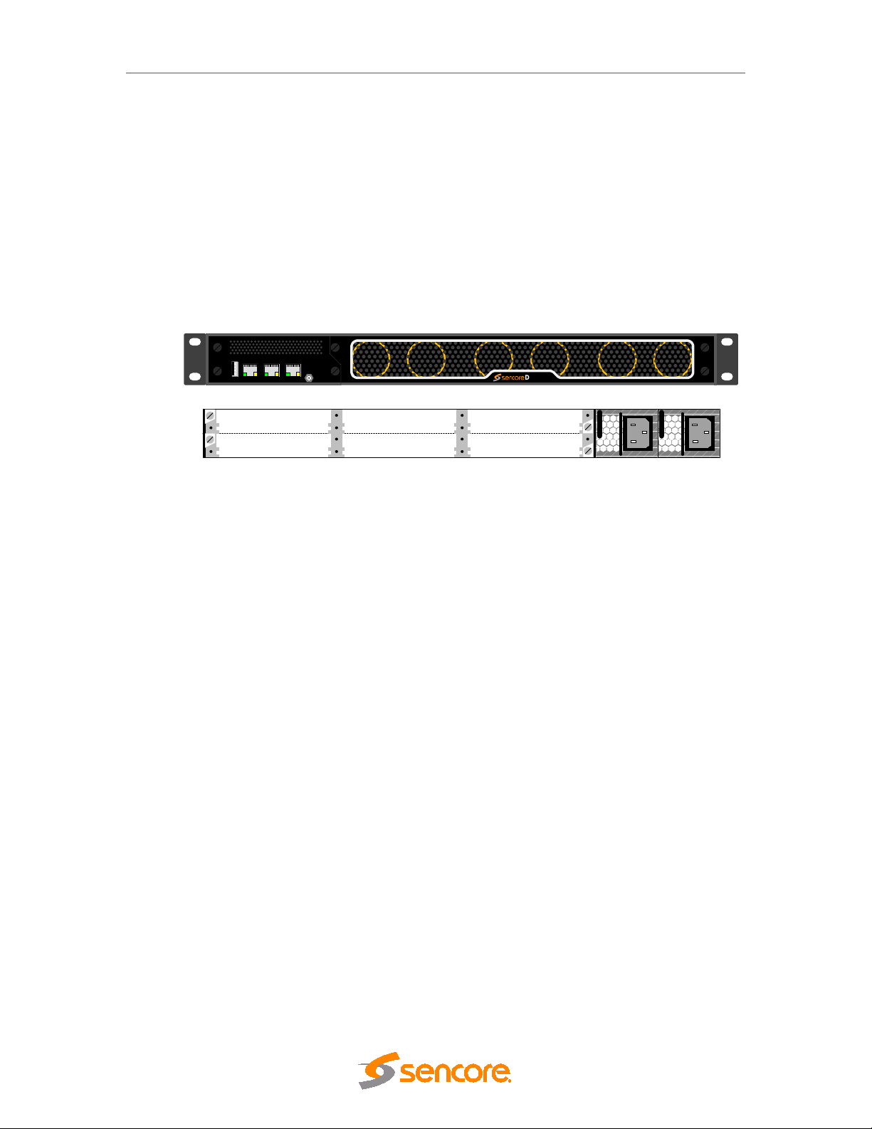
2.1.2 1RU Chassis DMG 3200
The 1RU chassis for the DMG 3200 holds of a total of 6 slot positions plus a slot for the
Switch/IP module. The Switch/IP module is inserted in the front of the chassis, while the
modules for the other 6 positions are inserted in the back of the chassis. All modules are hotswappable, including power supplies and the fan module in front.
The 1RU chassis is equipped with dual 400W AC or 500W DC power supplies
Figure 2.5 shows the front and rear view of the 1RU chassis including a mandatory switch
module, power supply connectors, and module slots.
Figure 2.5 - 1RU chassis for DMG 3200 with dual power, switch module and available slots;
front and rear view.
This chassis can hold 2 power supply modules for redundancy purpose
2.1.2.1 Ventilation
This DMG 3200 has forced air flow from front to back allowing for multiple units to be stacked
above each other with no space in between. However, adequate space must be provided in
front of and behind the unit for effective ventilation.
The DMG 3200 has 6 fans in front. Fan speed is temperature controlled. If one fan fails,
remaining fans will increase speed to compensate. The whole Fan module, containing all 6
fans, can be hot swapped. If, during fan module replacement, the temperature on the inserted
modules exceeds a certain critical temperature, the unit will shut down, to prevent damage of
the inserted modules.
2.1.2.2 Replacing the power supply m odule
This 1RU chassis can be installed with one or two hot swappable power supply modules. The
modules can be exchanged from the rear of the unit. The chassis delivered with a single power
module can be updated by acquiring additional power module.
If power is lost in one of the Power supplies, the other can feed the entire chassis. It is
recommended to connect each input power at different circuits.
Page 15 (306)
Page 16

DMG 3200/3100/3000 – User Manual
and key, or any other safety device, and in addition the site will be
2.1.3 Safety Considerations
The unit must be connected to a grounded power connection. The power input connector is a
disconnect device. To remove the power from the device, the power cables needs to be
physically removed from the power input connector.
Mandatory Safety Instr uctions
1 The equipment must be installed by a qualified person.
2 For that equipment with grounding, connect the driver before connecting the power
cord. So opposite the power cord must be removed before removing the driver of
the ground.
3 The equipment must be installed in a restricted area where:
• Only qualified technicians have access or who know the most important
safety measures.
• Access to the area where the devices are installed will be using a tool, lock
controlled by an authorized person.
Page 16 (306)
Page 17

DMG 3200/3100/3000 – User Manual
2.1.4 Installation
2.1.4.1 Power supply rating
The 4RU chassis is supplied with either a 100-240V AC 50/60 Hz power or -48V DC power.
The 100-240V AC 50/60 Hz power supply is rated for maximum 300W, 400W or 800W
48V DC power is rated for maximum 400W. Figures 2.6. 2.7, 2.8, 2.9, 2.10, 2.11 and 2.12
below shows the power supply inlets.
The 1RU chassis is supplied with a 100-240V AC 50/60 Hz power rated for maximum 200W
for product models DMG 3100.
The 1Ru chassis, product model DMG 3200, is supplied with single or dual 100-240V AC, 4763Hz , 400W power, or with single or dual -48V DC, 500W power.
2.1.4.2 4RU chassis with 300 and 400W AC Power
The chassis can be hold two power supplier for redundancy and has independent power inlets
for the two supplies.
1
. The -
Figure 2.6 - Power Input for 4RU chassis with 300 and 400 Watt AC power
1
Contact Sencore for more information.
Page 17 (306)
Page 18

DMG 3200/3100/3000 – User Manual
2.1.4.3 4RU chassis with 800W AC Power
The chassis has two power supplies for redundancy with independent power inlets. The
power supplies and power inlets are located at the back of the chassis.
Figure 2.7- Power input for 4RU chassis with 800W power supplies
Page 18 (306)
Page 19

DMG 3200/3100/3000 – User Manual
2.1.4.4 4RU chassis with 400W DC (-48Volt) Power supply
The chassis can be hold two power supplier for redundancy and has independent power inlets
for the two supplies.
Figure 2.8– Front plate of dual 48V Power Supply in a DMG 3000
Figure 2.9 - Layout of 48V DC Power Supply Connector
2.1.4.5 1RU chassis Product model DMG 3200 with AC power
The power input connectors are located at the back of the unit.
Figure 2.10 Power Input Connector for 1RU Chassis, product models DMG 3200 with AC power
Page 19 (306)
Page 20

DMG 3200/3100/3000 – User Manual
0 Volt
-48
volt
Chassis Ground
2.1.4.6 1RU chassis Product model DMG 3200 with DC power
The power input connectors are located at the back of the unit.
Figure 2.11 Power Input Connector for 1RU Chassis, product models DMG 3200 with DC power
2.1.5 Information on Disposal
This product must not be disposed of with other household waste. According
to the WEEE-directive, everyone that sells electrical and electronic products
shall ensure that the same products are disposed of in an environmentally
sound manner.
2.1.6 Laser Safety
The Optical SFP modules used in the DMG 3000/3100/3200 products are classified as class 1
laser products according to IEC 60825-1 and are classified as class 1 laser products per
CDRH, 21 CFR 1040 Laser Safety requirements.
Depending on the products configuration, the DMG 3000/3100/3200 products can be
equipped with multiple insertion modules containing housing for optical SFPs.
When installing SFP modules, please ensure that the module be placed in the housing present
at the front of the IP input/output module. Once inserted, the SFP module will become active.
Page 20 (306)
Page 21

DMG 3200/3100/3000 – User Manual
Max output power
(1)
Finisar
FTLF8519P2xCL
850 nm
-3 dBm
Finisar
FTLF8519P2xNL
850 nm
-3 dBm
Finisar
FTLF8519P2xTL
850 nm
-2.5 dBm
Finisar
FTLF1318P2xCL
1310 nm
-3 dBm
Finisar
FTLF1318P2xTL
1310 nm
-3 dBm
Finisar
FTLF1419P1xCL
1310 nm
5 dBm
Finisar
FTLF1518P1BTL
1550 nm
5 dBm
Finisar
FTLF1519P1xCL
1550 nm
5 dBm
Finisar
FTLF1519P1xNL
1550 nm
5 dBm
Finisar
FTLF1619P1xCL
1550 nm
5 dBm
Finisar
FWLF15217Dxx
1471, 1491, 1511,
1591, 1611
5 dBm
Finisar
FWDM16197Dxx
1471, 1491, 1511,
1591, 1611
5 dBm
Avago
Technologies
AFBR-5710Z
850 nm
-3 dBm
Avago
Technologies
AFBR-5715Z
850 nm
-3 dBm
Avago
Technologies
AFCT-5710Z
1310 nm
-3 dBm
Avago
Technologies
AFCT-5715Z
1310 nm
-3 dBm
OCP
TRXAG1SX
850 nm
-4 dBm
OCP
TRPEG1KVX-
E1G
1550 nm
5 dBm
(1) Class 1 Laser Safety per FDA/CDRH and EN (IEC) 60825 regulations
2.1.6.1 FDA/CDRH Compliant SFP modules
The below list of Optical SFP modules have been selected with regards to the FDA/CDRH
laser safety requirements as the only optical modules allowed used with the Sencore products
in the USA, and any other countries and states that require compliance according to
FDA/CDRH laser safety regulations.
Manufacturer Model wave length [nm]
2.1.6.2 Warning: Radiation
1531 1551, 1571,
1531 1551, 1571,
Caution – use of controls or adjustment or performance of procedures other
than those specified herein may result in hazardous radiation exposure.
Page 21 (306)
Page 22

2.1.6.3 Labels
DMG 3200
MODULAR
HI-DENSITY
HOT-SWAP
Status
Control
SWITCH
IPIO Control
Sync In
Data A Data B
DMG 3200
DATA A
DATA BCONTROL
The following illustrations show the labels attached to the Sencore products, according to
the standards.
A classification label is attached to the top cover of the DMG 3000/3100/3200 products.
DMG 3200/3100/3000 – User Manual
Figure 2.12 - classification label
3 Physical Module Configuration
3.1 Connecting switch modules
Configuration, management and monitoring of your Sencore unit is done via the management
port on the switch module. The switch module will contain the database for the full configuration
of the unit. One switch module (in some configuration two switch modules) must be installed in
all 1 RU and all 4 RU chassis.
Please refer to product datasheets for module identification.
3.1.1 Switch module with MMI
The switch module is equipped with one electrical connector (RJ45) for management.
Automatic sensing of 10/100/1000Mbit Ethernet connections is supported. For a 1000Mbit
connection, the Ethernet cable must be a category 6 cable.
The management port should be connected to your management network. Please refer to
section 4 for configuration.
3.1.2 Switch module with MMI and IP IO
Page 22 (306)
Page 23

DMG 3200/3100/3000 – User Manual
The switch module with management and two data ports is equipped with three electrical
connectors (RJ45) or one electrical connector (RJ45) and two SFP connectors. Two RJ45
electrical connectors or two SFP connectors are for data. The last RJ45 electrical connector is
for management
Automatic sensing of 10/100/1000Mbit Ethernet connections is supported on all RJ45 ports. For
a 1000Mbit connection, the Ethernet cable must be a category 6 cable.
The management port should be connected to your management network and the data port to
you data network carrying the video streaming content. Please refer to section 4 for
configuration.
Each port have a unique IP address and both data ports can be used at the same time as
wither 2 IP input ports (seamless or standalone), 2 IP output ports (cloned or standalone) or 1
IP input and 1 IP output port.
3.2 MMI MicroSD Installation
In order to enable Logo Insertion for the Encoder modules, a MicroSD card will need to be
installed in the MMI module. This will require physical removal of the MMI module from the unit.
Once the module has been removed, you will need to take the MicroSD card provided by
Sencore and insert this into and ‘click’ this into the MicroSD holder as shown below:
Figure 3.1 – MicroSD slot
In order to remove the MicroSD card, this can be pushed and then removed.
3.3 Connecting Input Signals
Please refer to product datasheets for module identification.
3.3.1 IP Input
This applies to the following modules::
• Standalone IP Input
• Dual IP module (Input mode)
The standalone IP input module is equipped with two electrical connectors (RJ45) and one SFP
connector. One RJ45 electrical connector and the SFP connector are for data. The second
Page 23 (306)
Page 24

RJ45 electrical connector marked “control” is not in use. It is not required to configure the IP
address or connect the port to the IP network.
The Dual IP module is equipped with two electrical connectors (RJ45) and two SFP connector.
Automatic sensing of 10/100/1000Mbit Ethernet connections is supported. For a 1000Mbit
connection, the Ethernet cable must be a category 6 cable.
The IP address for both the electrical (RJ45) and the optical (SFP) connectors for data is the
same. Consequently both connectors cannot be used simultaneously. These inputs are
automatically activated by IP connection. The first port activated (by establishing a link to the
router) will be the active port. To activate the other port, remove the cable from the active port.
3.3.2 ASI Input
Each ASI input module has three independent ASI inputs. The ASI connector is a 75Ω BNC
connector. The maximum input rate per connector is 212Mbit/s in burst mode.
The ASI module is equipped with an electrical connector (RJ45) marked “control” that is not in
use. It is not required to configure the IP address or connect the port to the IP network.
3.3.3 DVB-S/S2 Input
DMG 3200/3100/3000 – User Manual
The DVBS-S/S2 supports both DVB-S (QPSK) and DVB-S2 (with DVB-S2 license). Each DVBS/S2 input module has 4 independent L-Band inputs. Each input is a 75Ω F that can be
connected either directly to an LNB, an L-Band distribution amplifier, or switch. The maximum
input level is -25dBm. The recommended input level is between -30dBm and -40dBm.
One ASI output port is available for monitoring. Any of the four L-Band inputs can be copied to
the ASI output without affecting the services in use. The ASI connector is a 75Ω BNC
connector.
The DVB-S/S2 module is equipped with an electrical connector (RJ45) marked “control” that is
not in use. It is not required to configure the IP address or connect the port to the IP network.
3.3.4 COFDM Input
Each COFDM input module has one 75Ω F connector. The input is distributed to four tuners
internally, so each module can receive four independent frequencies. The maximum input level
is -15dBm. The recommended input level is between -30dBm and -50dBm. (An older version of
this module exists with different input levels.)
One ASI output port is available for monitoring. Any of the four COFDM inputs can be copied to
the ASI output without affecting the services in use. The ASI connector is a 75 Ω BNC
connector.
Page 24 (306)
Page 25

The COFDM module is equipped with an electrical connector (RJ45) marked “control” that is
not in use. It is not required to configure the IP address or connect the port to the IP network.
3.3.5 DVB-T/T2 Input
Each DVB-T/T2 input module has one or four 75Ω F connector. For the module having one
input connector, the input is distributed to four tuners internally, so each module can receive
four independent frequencies. For the module with 4 inputs, each input is directly connected to
a tuner. The maximum input level is -10dBm (both modules). The recommended input level is
between -20dBm and -40dBm (optimal lever will depend on modulation used).
3.3.6 QAM A/C Input
Each QAM input module has one 75Ω F connector. The input is distributed to four tuners
internally, so each module can receive four independent frequencies. The maximum input level
is -15dBm. The recommended input level is between -30dBm and -50dBm.
One ASI output port is available for monitoring. Any of the four QAM inputs can be copied to the
ASI output without affecting the services in use. The ASI connector is a 75Ω BNC connector.
The QAM module is equipped with an electrical connector (RJ45) marked “control” that is not in
use. It is not required to configure the IP address or connect the port to the IP network.
DMG 3200/3100/3000 – User Manual
3.3.7 8VSB Input
Each 8VSB input module has four independent 75Ω F connectors.
One ASI output port is available for monitoring. Any of the four 8VSB inputs can be copied to
the ASI output without affecting the services in use. The ASI connector is a 75Ω BNC
connector.
The 8VSB module is equipped with an electrical connector (RJ45) marked “control” that is not in
use. It is not required to configure the IP address or connect the port to the IP network.
3.3.8 QAM-B Input
Each QAM-B input module has four independent 75Ω F connectors.
One ASI output port is available for monitoring. Any of the four QAM-B inputs can be copied to
the ASI output without affecting the services in use. The ASI connector is a 75Ω BNC
connector.
The 8VSB module is equipped with an electrical connector (RJ45) marked “control” that is not in
use. It is not required to configure the IP address or connect the port to the IP network.
3.3.9 SDI Encoder
The SDI Encoder module has 4 BNC inputs that vary in functionality depending on the mode.
These functions are as follows:
• SD Encoder – Port A, B, C and D are in SDI mode and link to the 4 corresponding
• HD Encoder – Port A and B are in HD-SDI mode and link to the 2 corresponding
Page 25 (306)
internal encoder ports
internal encoder ports
Page 26

DMG 3200/3100/3000 – User Manual
• HD + AES Encoder – Ports marked HDSDI A and AES A link to channel A internally
while HDSDI B and AES B link to channel B
Page 26 (306)
Page 27

DMG 3200/3100/3000 – User Manual
Pin #
Function
1
A Right +
2
A Right -
3
B Right +
4
B Right -
5
GND
6
C Right +
7
C Right -
8
D Right +
9
D Right -
10
GND
11
GND
12
AES 1 +
13
AES 1 -
14
GND
15
AES 2 +
16
AES 2 -
17
GND
18
GND
19
A Left +
20
A Left -
21
B Left +
22
B Left -
23
C Left +
24
C Left -
25
D Left +
26
D Left -
3.3.10 Analog Encoder
The Analog encoder module has 4 High Density BNC input ports which correspond to the
internal ports. As well as this, there is one HD DSUB 26 male connector for audio. The pin-out
for this is as follows:
Page 27 (306)
Page 28

DMG 3200/3100/3000 – User Manual
Data from backplane
MOD 1
MOD 2
MOD 3
MOD 4
QAM Modulator board
The QAM modulator consists of
four modulator chips, each
carrying up to
4 carriers. The
frequency is set only for the first
carrier of each modulator. The
remaining three carriers per
modulator follow regular spacing.
3.4 Connecting Output Signals
3.4.1 IP Output
This applies to the following modules:
• Standalone IP Output
• Dual IP module (Output mode)
The standalone IP output card is equipped with both an electrical connector (RJ45) and one
optical (via the SFP module) for data. The RJ45 connector marked “control” is not in use. It is
not required to configure the IP address or connect the port to the IP network.
The Dual IP module is equipped with two electrical connectors (RJ45) and two SFP connector.
Automatic sensing of 10/100/1000Mbit Ethernet connections is supported. For a 1000Mbit
connection, the Ethernet cable must be a category 6 cable.
The IP address for both the electrical (RJ45) and the optical (SFP) connectors for data is the
same. Consequently, both connectors cannot be used simultaneously. These inputs are
automatically activated by IP connection. The first port activated (by establishing a link to the
router) will be the active port. To activate the other port, remove the cable from the active port.
3.4.2 ASI Output
Each ASI output module has four independent ASI outputs. The ASI connector is a 75Ω BNC
connector. The maximum output rate per connector is 212Mbit/s in burst mode.
3.4.3 QAM Output
Each QAM output module has two 75Ω F connectors which carry up to sixteen frequencies.
Page 28 (306)
Figure 3.2 - QAM Modulator
Page 29

DMG 3200/3100/3000 – User Manual
3.4.4 COFDM Cable Output
Each COFDM output module has two 75Ω F connectors which carry up to four frequencies.
3.4.5 DVB-T/T2 Output
The DVB-T/T2 output module has 4 50 Ohm BNC outputs, two for output A and two for output
B. Both outputs have a RF and Test port. The RF port will output the level configured in the
system while the Test port will be 20 dB lower and can be used for monitoring.
3.4.6 DVB-S/S2 Output
There are two variations of the DVB-S/S2 output module:
• L-Band Output – This module has two SMA RF outputs (50 Ohm), one for each of the
output channels A and B, and two monitor ports which are F-Type connectors (75
Ohm). The RF level of the monitor ports is 20 dB below that configured in the GUI for
the RF outputs.
The RF output can be muted with an external unit by applying 5V to the mute
connector. Channel A and Channel B can be muted individually. The connector for
Mute is a 2.5 mm headphone jack. For more information on this functionality, contact
Appear TV’s Support Team.
• IF Output – This module has 4 F-Type connectors which are 75 Ohm outputs. For
each port there is a RF and Test port. The RF port corresponds to the output power
level configured in the GUI, while the Test is the same level -20dB.
4 Administrative Settings Configuration
This chapter describes how to conduct initial configuration of the unit, such as setting its IP
address, changing the GUI’s password, setting the unit’s time as well as handling licenses for
the modules in the unit.
4.1 Accessing the Web Interface
All modules in the unit are controlled via the web interface provided with it. The unit Man
Machine Interface (MMI) software runs on the switch module via the connector marked as
“Control”
Default MMI IP address is 192.168.1.100. To change the network settings of the device please
follow the steps described below.
Connect a PC directly to the device (the Ethernet port marked “Control” on the switch module)
with an Ethernet cable.
Set the IP address of the Ethernet adapter of the PC to a fixed address in the same segment
(e.g. 192.168.1.99). Refer to the operating system’s manual for details on setting the IP address
on the PC.
Start an internet web-browser and type 192.168.1.100 in the address field.
Page 29 (306)
Page 30

DMG 3200/3100/3000 – User Manual
Ensure that caching is disabled in the web browser.
If you have previously connected to a unit with the same IP address, the ARP table
on your computer might be inaccurate. To delete the old ARP entry, type arp-d
192.168.1.100 in a command prompt.
Page 30 (306)
Page 31

DMG 3200/3100/3000 – User Manual
The following screen will appear though the exact configuration of the unit will vary.
The screen area is divided into several sub-areas: a Navigation Pane on the left, a main
display page on the right and footer at the bottom of the page. The Navigation Pane is used to
access various nodes, while the footer displays alarms. Please note that the alarm area can be
expanded by clicking on the arrow in the right bottom corner.
The button highlighted in the above figure toggles between the auto-hiding and always visible
Navigation Pane modes. In auto-hide mode, the Navigation Pane frees up the space for the
main pane. This is useful not only for devices with smaller screens such as netbooks but also
for viewing large tables of data on the main pane.
By default, this feature is disabled, and the Navigation Pane is always visible.
Figure 4.1 - Web Home Page
Page 31 (306)
Page 32

DMG 3200/3100/3000 – User Manual
Figure 4.2 - Minimized Navigation Pane when auto-hide is enabled
Figure 4.3 - Hovering mouse over the minimized Navigation Pane will show the full pane
Page 32 (306)
Page 33

DMG 3200/3100/3000 – User Manual
4.1.1 Assigning an IP Address
Click on the Admin node in the Navigation Pane and the window in Figure 4.4 will be
displayed. This window shows all installed modules with their respective network settings; the
MMI module is in slot 0 or slot 17 (marked as mmi in Type).
Figure 4.4 - Admin View
Select the switch module hosting the MMI and a module configuration similar to the one below
Figure 4.5 will be displayed.
Page 33 (306)
Page 34

DMG 3200/3100/3000 – User Manual
Figure 4.5 - Admin Properties View
In the Admin Properties view, it is possible to configure the Default Interface, Control Port,
and Data Port. Control ports on all input, output and processing except scrambling, bulk
descrambling and EPG modules do not need to be configured.
Default Interface This parameter allows you to select the Management Port to be
used for managing the Web GUI.
For Switch modules with IP interfaces, the Management Port can
be the Control Port, Data Port, or a VLAN (previously added).
Control Port
IP Address
Gateway Address
Subnet Mask
DNS Server
Data Port
IP Address
Gateway
Address
Subnet Mask
Auto Negotiation
Link Speed
IP address used solely for management. It cannot be used for
multicast reception as it is not for data input.
Gateway address of the network used for management
Subnet mask
Specify DNS Server for Control port applications (ie NTP)
IP address used for multicast reception
Gateway address of the network used to access external resources
Subnet mask
Enabled or disabled
Choose from:
• Max
• 100
• 1000
Current Link
Speed
Enable ICMP
Page 34 (306)
Current detected link speed of the Ethernet interface
By default all ports on the Dataport are closed (ie firewall). Enabling this
option enables the port for ‘ping’ to be open. See further details in 4.1.4.
Page 35

DMG 3200/3100/3000 – User Manual
VLANs
Save the settings and connect the unit to your local network. Reconnect to the Web GUI using
the MMI address.
The IP Input port can support up to 25 Virtual LANs (VLANs) depending on
the module type and they can be defined in the Admin Properties view.
The VLANs may then be associated with IP input streams when configuring
input multicasts. To add and remove VLANs, click edit. The dialog below
will be displayed:
Figure 4.6 - Setting up Virtual LANs
Click to add VLAN tags and to remove them.
If an active VLAN is removed, the associated IP inputs are reset so that they
will not be part of that particular VLAN group.
Please note that the following addresses ranges are reserved for internal use
and not available to be configured:
Switch: 192.168.0.xxx
Switch w/ IP: 192.168.0.xxx and 192.168.2.xxx
4.1.2 IPv6 Address Support
IPv6 support is available for management and data port s of the Switch module, both Contr ol
and IP versions. The following options are supported:
• Support for simultaneous IPv4 and IPv6 addresses, both for management and data
ports.
• Management (GUI/SNMP) using IPv6 address
• IP inputs using IPv6 addresses
• IP output using IPv6 addresses
4.1.2.1 Management GUI
Page 35 (306)
Page 36

DMG 3200/3100/3000 – User Manual
Figure 4.7 – IPv6 Address in Admin Page
Figure 4.8 – Manual IPv6 Address
Page 36 (306)
Page 37
DMG 3200/3100/3000 – User Manual
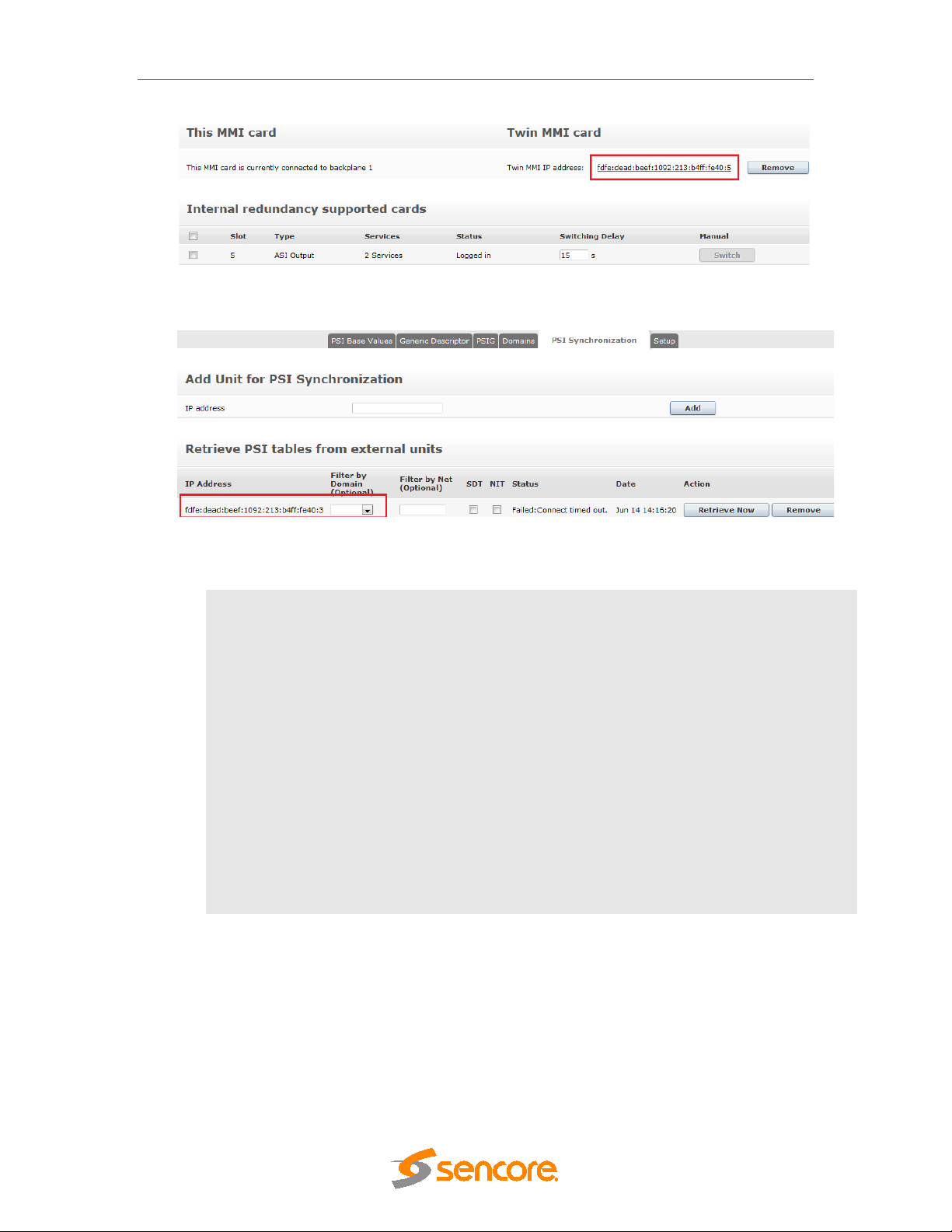
Figure 4.9 – IPv6 Internal Redundancy
Figure 4.10 – IPv6 PSI Synchronization
Default interface
Auto IPv6 Address
Manual IPv6
Address
IPv6 NTP server
Internal Redundancy
PSI Synchronizati on
Default interface for Management interface. This can be selected
between control and dataports, as well as any configured VLANs.
All interfaces will automatically get an IPv6 address which is generated
based on router advertisements. The address will have a correct prefix,
and be unique on the connected network.
When enabling Manual IPv6 Address, the port can be configured with a
manual IPv6 Address. Prefix length and Gateway address is also set.
The unit can connect to an IPv6 NTP server by inserting a valid IPv6
address in the “NTP server” field.
The twin MMI card can use an IPv4 or IPv6 address.
The PSI Synchronization units can use an IPv4 or IPv6 address
4.1.3 Management over IP-Data Port and VLANs
In the Admin section of the MMI card, it is now possible to set the default interface for the
Management interface. This includes the GUI, Maintenance Center and SOAP operations.
This will allow you to configure the IP dataports on the switch card, or a configured VLAN for the
default management interface.
After configuring VLANs we can see it in the drop down list in the control port refer below figure.
Page 37 (306)
Page 38

DMG 3200/3100/3000 – User Manual
Figure 4.11 - Setting up Virtual LANs via Management port
4.1.4 Broadcast Firewall
Each IP Dataport is by default configured with IP Firewall features. This has the following
configuration in terms of ports:
• Secure (Default)
o ARP open by default
o ICMP (ping) - by default closed, but able to be opened
o IGMP -enabled on the IP input card
o OSPF - enabled for output ports when OSPF is selected for Output
Redundancy
o PIM - enabled for output ports when the PIM is enabled for Output
Redundancy
o UDP Filter –Any UDP traffic that is not a configured multicast is blocked
• Public (Enabled when data-port is set as MMI port in the Admin Page)
o All protocols open
4.1.5 Internal Time Clock Setting / Network Time Protocol (NTP) Server
The unit internal time may be configured manually, or it may be configured with a Network
Time Protocol (NTP) server to set and update the system’s date and time.
Open the Admin view in the Navigation Pane and select the module hosting the Man Machine
Interface (MMI).
To configure the NTP Server settings, enter the following data below:
IP Address
Local Timezone
Page 38 (306)
IP address of the NTP server
Your local timezone
Page 39

DMG 3200/3100/3000 – User Manual
To set the internal time manually, simply click on Edit time & date to produce the dialog below.
Figure 4.12 – Setting the Time and Date
Set the date and time accordingly.
Once the internal time has been configured, it will be displayed in the Current Time field, under
the Time and Date section.
4.1.6 Automatic Daylight Saving
The Time Zone can also be selected on the Admin page for automatic updates of daylight
savings for the system time.
If you required the Time Zone file for a given region, please contact procare@sencore.com
This file can be installed from the Maintenance Center, by selecting and uploading to the MMI
slot.
.
Page 39 (306)
Page 40

DMG 3200/3100/3000 – User Manual
Figure 4.13 - Login Management Section
4.1.7 Password Protection in the GUI
For enhanced security the Web interface supports password protected access. This feature is
disabled by default but may be enabled easily from the GUI.
To authenticate GUI access, in the MMI Admin view, click Change under the Password
Protection entry in Login Management. Check the appropriate checkbox and click Apply.
Reboot the MMI module for this change to take effect.
Figure 4.14 - Login Management Section
Figure 4.15 Password Configuration
The Exclude status from authentication option is provided in cases where only certain parts of
the GUI need to be protected. If this checkbox is checked, only the Service View, Hardware
View and Active Alarm View will be excluded from authentication. All other pages, including
Alarm History will require authentication to be viewed.
4.1.8 Changing the Passwor d for the GU I
Page 40 (306)
Page 41

DMG 3200/3100/3000 – User Manual
The secure login supports one pre-defined user account – the admin user. The password
protects the web GUI only, i.e., the SOAP interface is not password protected.
User
Default password
To change the password click Change. The following dialog will appear:
Type in the new password and click Set. Finally, click Close to exit the dialog. Reboot the MMI
module for the new password to take effect.
4.1.9 Optional Languages
It is possible to specify one or two default languages which will always be available when
configuring decoder modules. Since the drop-down list of available languages only includes
languages currently present in the transport stream, this enables the operator to select
languages expected to be present in the transport stream at a later point in time.
admin
admin
Figure 4.16 - Changing the Password
Open the Admin view in the Navigation Pane and select the module hosting the MMI.
Figure 4.17 - Optional Languages
Enter up to two additional languages for the Optional Languages field. Language codes should
be separated by a comma, e.g., nor,dan.
Language codes are defined in the ISO 639 specification.
4.2 Configuration of Clock reference module
Please refer to the Terrestrial Solution Configuration Guide for more information on this module
and its configuration.
Page 41 (306)
Page 42

4.3 Licensing
Licenses for modules in the unit are hosted by individual cards. Hence, the available features
will not be determined before the cards are registered or logged into the MMI board. The table
below lists all available licenses:
Module License Description
audiolevel number-of-audio-pids Enables the number of audio PIDs with audio leveling.
DMG 3200/3100/3000 – User Manual
bulkdscr number-of-
cofdmoutcable
dvbs2 dvbs2 Enables the DVB-S2 demodulation options
epg epg Enables EPG.
asiout mip-inserter Enables MIP on the ASI output port.
switch/ipin ipin-pro-mpeg-fec Enables the reception of IP FEC streams on supported hardware
switch/ipout ip-out-mpts
descrambled-services
verimatrix Enables communication with the Verimatrix CA system
latens Enables commnunication with Latens system
modulation-cofdm Enables COFDM modulation for the output.
num-ts Enables the number of maximum possible output multiplexes.
dvbs2-input-multistream Enables Multistream reception option for the DVB-S2 module
seamless-ip-in Enables IP input seamless switching
Enables the number of services for bulk descrambling.
MPTS refers to Multiple Program Transport Stream. Without the ip-out-mpts
license, only SPTS (Single Program Transport Stream) is available.
qamout-a modulation-qam Enables QAM modulation for the output.
dvb-t2 dvbt2-input Enables the DVB-T2 demodulation options.
encoder number-of-hd-encoders Enables the number of HD services to be encoded.
transcoder number-of-hd-encoders Enables the number of HD services to be transcoded.
Page 42 (306)
ip-pro-mpeg-fec Enables IP Forward Error Correction (FEC) option supported hardware
output-redundancy Enables output redundancy for the module.
num-ts Enables the number of maximum possible output multiplexes.
number-of-sd-encoders Enables the number of SD services to be encoded.
number-of-statmuxchannels
Number of channels with Statistical multiplexing enabled
Page 43

DMG 3200/3100/3000 – User Manual
scrambled and the corresponding
Module License Description
number-of-sd-encoders Enables the number of SD services to be transcoded.
number-of-statmuxchannels
transcoderms
scrambler number-of-scrambled-
hd-encoding Enables HD encoding of input source
Dolby Digital Plus
Professional Decoder
services
aes-cbc-irdeto Vendor specific scrambling license.
pvr-mode, pes-clear Enables PVR mode for the scrambler and ensures that the pes headers are not
Table 1 - Types of Licenses availab le
If a licensed feature is used without the correct license installed, the system will produce a
License Violation warning. Use the License node to find which licenses are acquired and
available.
4.3.1 Ordering a License File
Number of channels with Statistical multiplexing enabled
Enables decoding of Dolby Digital ( A C-3) and Dolby Digital Plus (E-AC-3) inputs,
Enables the number of services to be
encryption algorithm.
scrambled.
* pes-clear and pvr cannot be active simultaneously
Use the License node to order a license file. Flag the required licenses using the check boxes.
The Order License button will produce a license order file which should be sent to Sencore. A
matching license file will then be returned.
4.3.2 Installing a License File
A valid license file may contain licenses for one or several cards. This means that one license
file may be used for several units. The installation process will scan the file and if a matching
serial number is found the license will be installed on the respective card within the unit. The
license file is signed; if edited, it will be invalid.
Figure 4.18– Licensing
Page 43 (306)
Page 44

Usually, the license file will be sent in a ZIP file and can be loaded directly to the GUI.
Once a license file is available from a machine with access to the web GUI, select the file and
click Install License. If no warnings are displayed, the additional privileges should now be
available.
4.3.3 Demo Licenses
When required, a time limited demo license can be provided in order to evaluate licensed
features. The procedure to load a demo license is the same as a purchased license.
Once installed, the GUI will notify the user by creating an alarm about the presence of the demo
license and what date it expires. When the demo license expires, then the card will be rebooted
at 4 AM UTC time. After the card has rebooted, the demo license is no longer present on the
card.
DMG 3200/3100/3000 – User Manual
5 Input Configuration
This chapter describes the Inputs node in the GUI and how to analyze the available inputs.
5.1 The Inputs Node
The unit can be configured to host a number of different input m odules. Open the Inputs node
from the Navigation Pane to view all available input modules
Page 44 (306)
Figure 4.19 – Demo License
Page 45

DMG 3200/3100/3000 – User Manual
Figure 5.1 - Inputs Node
The following information is available in the Inputs node:
Slot
Slot position in the chassis
Type
Services
Total TS
Rate [Mbps]
CC Errors
TS Errors
RTP
Sequence
Errors
Output Rate
[Mbps]
Each input module available in the unit has some common ana lysis features; they all suppor t
manual definition of input PSI. The coming sections will describe these common features
followed by details on how each input module can be configured.
Type of input module
Number of services present in the transport stream
Total bandwidth of the incoming transport stream
Number of Continuity Count er (CC) errors detected on all input ports since las t
reset; CC errors indicate that one or more packets are lost.
Number of Transport Stream (TS) errors detected on all input ports. TS errors
indicate problems with the incoming TS structure of the streams
Real-time Transport Protocol sequence errors since last reset (applies to IP only)
Rate of active services transmitted to the backplane
5.2 Input Analysis
For each input module the unit provides detail ed MPEG/DVB/ATSC trans port stream anal ysis
for all available input streams. The following information is provided by the input analysis
engine:
• Port specific status
• PSI/SI analysis of all input services
Page 45 (306)
Page 46
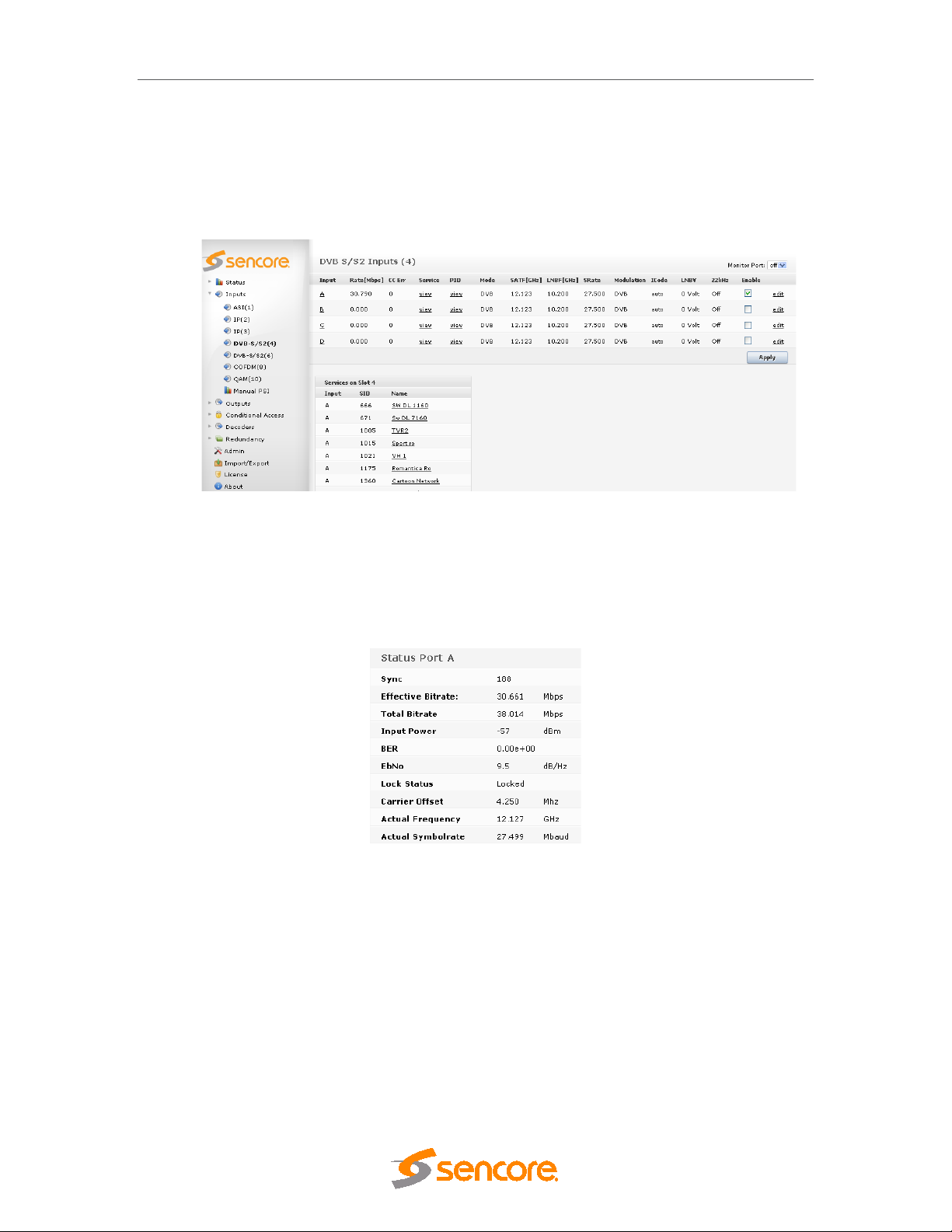
DMG 3200/3100/3000 – User Manual
• PID display – listing al l input PIDs f or each input, with implicit highlighting of CC errors ,
PCR flag and scrambling bits (odd/even)
This information is accessible by expanding the Inputs view in the Navigation Pane. The
following example (Figure 5.2) is based o n a DVB-S/S2 i nput module, but the s ame applies to
all input modules.
Figure 5.2- Example of DVB-S/S2 Inputs
5.2.1 Input Port Analysis
Within the Inputs node, it is possible to access lower level information, e.g. port specific
information. To obtain port specific information for input modules with demodulators, click on the
port letter in the Input column.
Figure 5.3 - DVB-S/S2 Port Detailed View
For more details on actual parameters, refer to the configuration section for the respective input
type in this chapter.
Page 46 (306)
Page 47
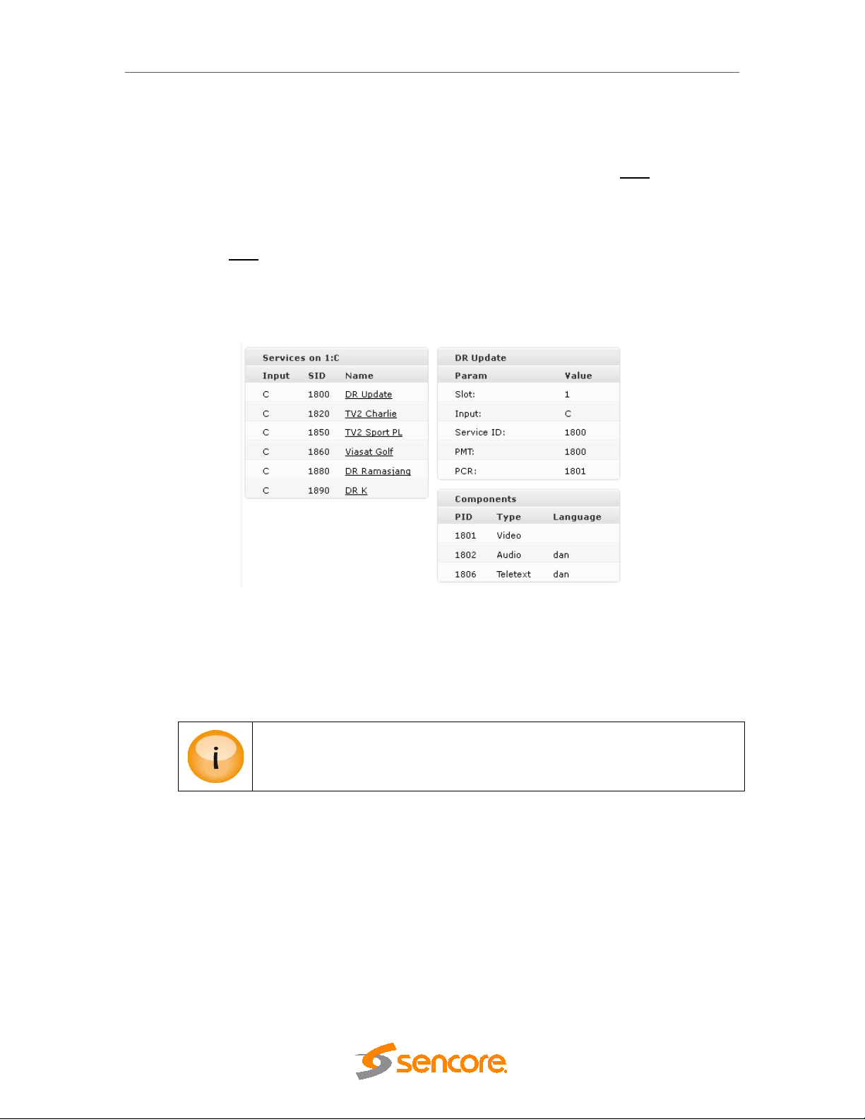
DMG 3200/3100/3000 – User Manual
5.2.2 Input Service Filtering and Analysis
It is possible to apply filters on information displayed in the GUI. Clicking on view in the Service
column for a selected multicast, results in only services associated with this multicast being
displayed. Clicking on one of the listed s ervices will display more detailed inf ormation about the
different PIDs like PMT, PCR, video, audio, etc.
Click on view in the PID column for ASI inputs will display only PIDs associated with the
selected input. Simply choose any PID to obtain more detailed information.
To access detailed PSI/SI analysis of the input services, click the respective service in the lower
pane. The detailed analysis result will appear next to it, on the right.
Figure 5.4 - Detailed PSI/SI Analysis of Input Services
The Audio language descr iptor is decoded. I n Figure 5.4, the audio is lis ted as dan, ie Danish.
However, if no language descriptor is present the unit will auto-generate a descriptor for internal
usage and they will be named A01, A02, etc.
Details of the PSI/SI an alysis are not 10 0% DVB com pliant, but it does includ e
the most commonly used tables and descriptors.
Page 47 (306)
Page 48

DMG 3200/3100/3000 – User Manual
5.2.3 Input PID Analysis
The PID view lists a ll PIDs d etec ted f or a g iven por t. This list is accessible via the PID s c olumn
in the top pane.
Figure 5.5 - PID Scrambled with Even Control Word
Figure 5.6 - PID Scrambled with Odd Control Word
For an input containing scram bled ser vices the color of the scr am bled PIDs will togg l e bet ween
Blue and Red as the ODD/EVEN bit toggles.
In Figure 5.5 and Figure 5.6 we can for example see that PID 521:
• is scrambled as it is colored,
• contains PCR as it is bold, and
Page 48 (306)
Page 49

DMG 3200/3100/3000 – User Manual
• no CC errors have occurred since none of the PID numbers are inverted in color.
It is possible to res et the CC error counters. This r es et is a gl oba l o per ation for all inputs and is
done with the Reset CC button in the Inputs node.
To obtain PID specific details, simply click on view in the PID column.
Figure 5.7 - Selecting PID 20
Selecting PID 20 (Figure 5.7), we see that it is a TDT PID. Also, its bitrate and num ber of CC
errors are presented.
Selecting PID 550 gives a slightly different info as it is a video PID:
Figure 5.8 - Selecting PID 550
Page 49 (306)
Page 50

5.3 Manual PSI
• Manual
To manually define input P SI se lect Inputs Manual PS I from the N avigation P ane.
In case the input PSI information is not available, a predefinition of the PSI is necessary in order
to configure a service that is occasionally available. This could be used, for instance, to
predefine some services for dynamic VOD usage.
DMG 3200/3100/3000 – User Manual
Figure 5.9 - Manually define Input PSI
In the Manual PSI node, click Add Service and enter the appropriate values matching the
incoming stream. The following information is displayed:
Service Id
PCR PID
PMT PID
Type
PID
Service ID for the manual service
PCR PID for the manual service
PMT PID for the manual service
Select one of the following component types:
• Video (MPEG-2)
• H264
• Audio (MPEG-2 audio)
• AAC
• AC-3
• Private Sections
• PES Private
PID number for the component
Properties
Page 50 (306)
Additional information for the component, if necessary.
Page 51

DMG 3200/3100/3000 – User Manual
The PMT PID may be defined with any value from 32 to 8190, but ensure that
it is unique in an MPT S configurati on scenario. Also, if this input is par t of an
outgoing digital stream, the PMT PID here is the PID value that will be
assigned for the outgoing PMT.
When an input service is defined the following tables are generated:
• PAT
• PMT
All other table analysis is ca nc elle d f or this input port. T he r esult is liste d in t he G UI ( s ee Figure
5.10).
Figure 5.10 - Table Analysis when an Input Service is defined
This entry may be edited or deleted later using the corresponding icons on the left.
5.3.1 MPTS Support
If multiple services are defined for one input, they effectively represent a MPTS.
To check that the manuall y defined input has entered th e system correctly, select th e Inputs
node and ensure that the service information is present. In t he example below (Figure 5.11)
Service number 30 (under the Services panel) is represented with P SI even though the input
has not yet been added to the system.
Page 51 (306)
Page 52

DMG 3200/3100/3000 – User Manual
Figure 5.11 - Verifying manually defined Inputs
If manual PSI is defined f or an input port, all incoming ser vices must be defined.
It is not possible to define o nly one service m anually an d use t he incom ing P SI
to represent the rest.
5.3.2 PSI Modifications of input services
This PSI modification feature allows the user to modify existing incoming PSI, keeping
the other PSI information intact. The feature is currently implemented to solve two
specific scenarios.
• Add signaling to incoming “DVB Subt itling” and “EBU teletext” components in PMT.
Other component types can also be added but without any descriptors only.
• Change audio language descriptor of an incoming audio component.
5.3.3 Defining a component type for an incoming PID.
To define the PSI for an incoming PID
1) Select the input reference from the Input->PSI navigation Page.
2) Press the Add button and insert the appropriate information.
Page 52 (306)
Page 53

DMG 3200/3100/3000 – User Manual
• aac_latm
Figure 5.12– Defining Manual PSI
Figure 5.13– Defining component for service
Component PID
Component Type
Descriptor Type
Enter the PID value of th e incoming PID to which the s ignaling shall
be defined.
Specify the type of component.
Depending on the type of c om ponents differ ent descr iptor options will
emerge.
5.3.4 Changing the language descriptor of an incoming audio
PID
Type
Page 53 (306)
Figure 5.14 – Edit Language descriptor
The input PID to update.
The audio type where the language descriptor shall be replaced.
• Any
• mpeg-audio
• ac-3
Page 54

DMG 3200/3100/3000 – User Manual
• aac_adts
• e-ac3-e
Language
Override
The language signaled on the input. If this is not a filtering criteria then use
wildcard “*”
The new language descriptor to be used for the incoming component.
Note
• If several PIDs are matching the input filtering criteria’s, then the signaling for all
these components will be updated.
• If the input signaling is dual mono, and no Lan guage (source) is specif ied, then the
right channel descriptor will be replaced.
5.3.5 Edit options on existing manual PSI
Under the Manual-PSI node all current manual PSI rules will be listed. Not all rules can be
changed once they are defined. These are indicated with a blue circle with the “?” mark. To
change these components they need to be removed and re-added. The rules indicated with a
pencil can be changed without remove / add operation.
Figure 5.15 – Editing existing Manual PSI
Page 54 (306)
Page 55

DMG 3200/3100/3000 – User Manual
5.4 Input Modules
5.4.1 DVB-S/S2 Input
The DVB-S/S2 module supports both DVB-S and DVB-S2 inputs. The DVB-S2 functionality is
licensed and will only be visible in the GUI if a correct license is installed for the module.
The hardware revision 2.0 DVB-S/S2 input module includes a new advanced DVB-S2
demodulator. This input module is compatible with the DVB-S/S2 input card. The hardware
revision of the module is available on the About page in the web GUI.
In addition to the standard DVB-S2 the advanced module supports
• 16_APSK and 32_APSK mode.
• Multistream input
• Auto modulation detection mode.
Each DVB-S/S2 module can receive up to four individual L-Band satellite input streams. To
configure the module:
Switch to the Inputs node in the Navigation Pane
Select DVB S/S2 to display the module configuration (see Figure 5.17). Services available on
all four input ports will be listed in this view.
Figure 5.16- DVB-S2 Input
The DVB-S/S2 node sho ws all major configuration settings as well as the c urrent bitrate and
service information. The following parameters are available:
Page 55 (306)
Page 56

DMG 3200/3100/3000 – User Manual
Input
Rate [Mbps]
CC Err
Mode
SATF [GHz]
SRate
Modulation
ICode
LNBV
Port on the DVB-S/S2 input module
Incoming data rate
Continuity Counter Error – indicates that one or more packets are lost
PSI/SI Analysis mode.
Satellite Frequency
Symbol Rate – specify the symbol rate of the incoming DVB-S/S2
signal. The demodulator’s range is 950 – 2150 MHz.
Select one of the following modes:
Auto (only for HW Rev. 2.0)
DVB-S
DVB-S/S2_QPSK
DVB-S/S2_8PSK
DVB-S/S2_16APSK (only for HW Rev. 2.0)
DVB-S/S2_32APSK (only for HW Rev. 2.0)
Inner Code – specify the FEC overhead fraction
LNB Voltage – select the output voltage from the dropdown box
22kHz
Enable
The above list of parameters can be conf igured by clicking on the edit link to the right of each
input. The pop up dialog below will be displayed:
Switch the 22kHz output signal on or off
Enable the corresponding input port
Page 56 (306)
Page 57

DMG 3200/3100/3000 – User Manual
PLS Sequence
• 0.20
Figure 5.17 - Edit DVB-S/S2 Port Configuration
In this dialog, additional parameters can also be modified depending on the configured mode
and hardware version.
Pilot
Enable Multistream
type
Input Stream ID
PLS
Name
Activates the use of distribut ed pilot symbols (of the DVB-S/S2 standard)
for fine frequency estim ation and for detection of the presence of strong
phase noise. This is available on HW revision 1.0 only
Enable the Multistream
Either ‘gold’ or ‘root’ mode can be selected.
Multistream Input Stream ID. Note it is only possible to tune into one
Stream ID
Multistream PLS (Physical L ayer Scrambling). PLS is often ref erred to as
the ‘gold’ or ‘root’ code and will be pr ovided by your content provider if
required. Default value is 0
This parameter allows for eac h port in a module to be labeled. This label is
visible as a tooltip when the mouse cursor hovers over the port. Port
names are shown in the alarms when a non-empty string is set as the
name..
Page 57 (306)
Roll Off:
Select one of the following options:
• 0.15
Page 58

DMG 3200/3100/3000 – User Manual
• 0.25
• 0.35
• 5 MHZ
• Inversed
Acquisition range
Spectrum
Inversion
T2MIDe-encapsulation
T2MI PID
T2MI PLP
Preferred PCR pid
CBR if transparent
Select one of the following options:
• Auto
• 1 MHZ
• 2 MHZ
• 2.5 MHZ
The following options are available:
• Auto
• Normal
T2 de-encapsulation specifies to extract one PLP from T2MI stream
This is T2MI stream PID
This is T2MI stream PLP ID of the requires stream
This allows you to set a PC R PID in the inp ut multiplex as a priorit y
to use for de-jittering. If this PID is n ot available, then the next valid
detected PCR will be used. This is only valid for transparently
mapped streams.
This de-jitter mechanism will use the incoming CBR total bitrate as a
guide for the clock source of the stream. This is only valid for
transparent mapped and PID imported outputs.
Reduced input buffer size
To monitor any of the dem odulated DVB-S/S2 input signals, one of the DVB-S/S2 input ports
can be assigned to the output ASI m onitor interfac e. The demodulate d DVB-S/S2 input signal
will then be copied onto the monitor port for further analyzing or monitoring of the transport
stream. Normal operation will not be affected if the monitoring port is used.
Refer to the general input analysis description at the start of this chapter to analyze the input.
Click on the letter representing the input channel (A, B, C or D) to display the status parameters
for the specific input port. The resulting display is shown in the figure below.
Enable or disable Reduced Input Buffer for introducing a low latency
dejitter function.
Page 58 (306)
Page 59

DMG 3200/3100/3000 – User Manual
Figure 5.18 – DVB-S/S2 Status View
The following information is displayed:
Sync
Effective Bitrate
Total Bitrate
Input Power
EbNo
BER
SNR
Carrier Offset
Actual Frequency
Actual Symbolra te
Actual Modulation
MPEG sync number: 188 or 204
Effective bitrate of the input stream
Total bitrate of the input stream
Input power for the DVB-S/S2 signal in dBm
Energy per bit/(Noise per 1Hz BW)
Bit Error Rate
Signal to Noise Radio, indicated in dB
Carrier offset
Frequency reported by the demodulator
Symbol rate reported by the demodulator
Modulation reported by the demodulator
Lock Status
The status parameters EbNo and SNR will be 0 when the tuner is not locked.
In this dialog, additional parameter is present with only DVB-S Modulation:
Page 59 (306)
Lock status of the tuner
Page 60

DMG 3200/3100/3000 – User Manual
Pre-FEC_BER
5.4.2 ASI Input
The ASI input module can receive up to three/four individual ASI input streams depending on
the hardware revision. Each ASI input can support up to 213Mbit/s. To configure the module:
• Switch to the Inputs node in the Naviga tion Pane
• Select the ASI module you want to configure to display the module configuration.
Services available on all three ASI input ports will be listed in this view.
Bit error rate on the channel, before any FEC decoding.
Figure 5.19 - ASI Input
The ASI node shows all configurable settings as well as the current bitrate and service
information. The following parameters are available:
Input
Rate [Mbit/s]
CC Err
Mode
Enable
Port on the ASI input module
Incoming data rate
Continuity Counter Error – indicates that one or more packets are lost
Select one of the following modes:
o DVB
o DVB (SDT)
o MPEG
o ATSC
o OFF
The default mode is DVB. If the incom ing transport stream is not DVB
compliant, use MPEG mode instead.
Enable the corresponding input port
Page 60 (306)
Page 61
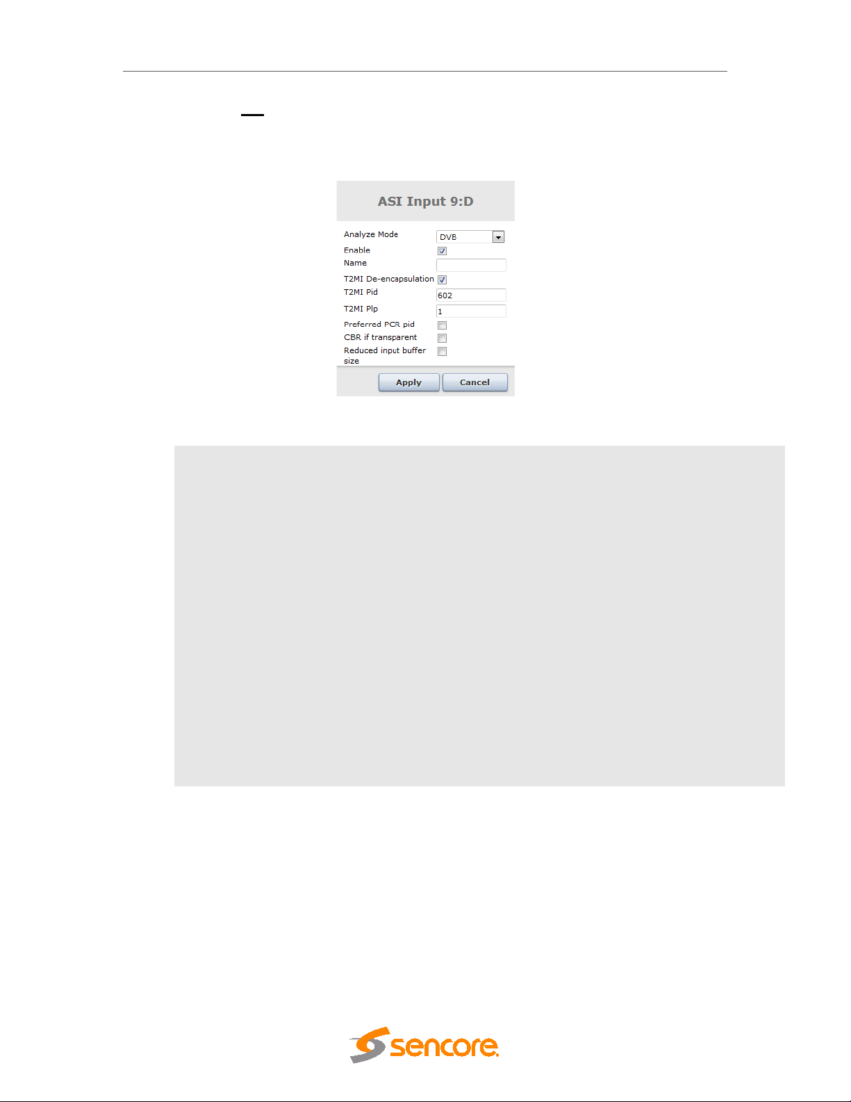
DMG 3200/3100/3000 – User Manual
T2MIDe-encapsulation
T2MI PID
T2MI PLP
Preferred PCR pid
CBR if transparent
Reduced input buffer
Enable or disable Reduced Input Buffer for introducing a low latency
Clicking the edit link on the r ight d isplays the dialog below, allowing f or the Mode, Enable, and
Name parameters to be edited.
Figure 5.20- ASI Edit Dialog
Name
size
The status parameters for the ASI module are shown in the f igure below. Click on the letter
representing the input channel (A, B or C) to display the status parameters for the specific input
port. The resulting display is shown in figure below.
This parameter allows for eac h port in a module to be labeled. This la bel is visi ble as
a tooltip when the m ouse cursor hovers o ver the port. P ort names are s hown in the
alarms when a non-empty string is set as the name..
T2 de-encapsulation specifies to extract one PLP from T2MI stream
This is T2MI stream PID
This is T2MI stream PLP ID of the required stream
This allows you to set a PCR PID in the input multiplex as a priority to use
for de-jittering. If this PID is not available, then the next valid detected
PCR will be used. This is only valid for transparently mapped streams.
This de-jitter mechanism will use the incoming CBR total bitrate as a
guide for the clock s ourc e of the str eam. This is only valid f or tr anspar ent
mapped and PID imported outputs.
dejitter function.
Page 61 (306)
Page 62
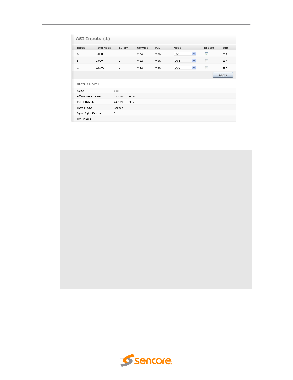
DMG 3200/3100/3000 – User Manual
guarantees that each data byte is preceded with two idle
Figure 5.21 - ASI Status View
The following information is displayed:
Sync
Effective
Bitrate
Total Bitrate
Byte Mode
Sync Byte
Errors
Bit Errors
MPEG sync number: 188 or 204
Effective bitrate of the input stream
Total bitrate of the input stream
The byte mode specifies how the TS data is transported over the AS I
link.
Burst Mode – Al l TS data bytes are sent without any idle s ymbols in
between
Spread Mode – The SI specification requires at least one idle byte
between each data byte, and each packet start indicator (0x47) is
preceded with at least two idle b ytes. The ASI output stream in Spread
Mode
symbols. This effectively reduces the maximum data rate to 1/3 of the
maximum ASI output rate, i.e. (213/3) Mbps. If higher rates are required,
use Burst Mode.
Number of sync byte errors on the incoming stream
Number of bit errors on the incoming stream
Page 62 (306)
Page 63
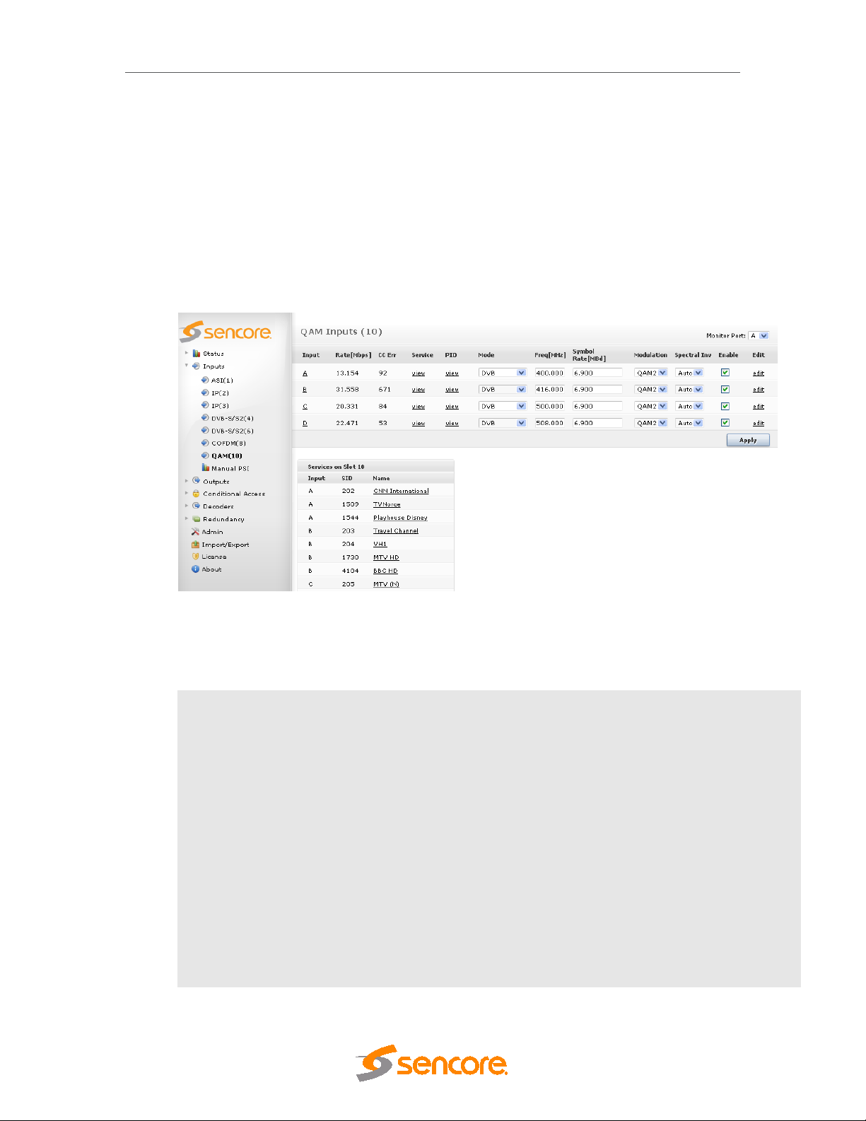
DMG 3200/3100/3000 – User Manual
5.4.3 QAM/DVB-C Input
The QAM/DVB-C input module can receive up to four individual QAM frequencies. The
QAM/DVB-C input modules com es in 2 HW versions; a 2 slot version referred to as Q AM input
and a 1 slot version referred to as DVB-C input. To configure the module:
• Switch to the Inputs node in the Navigation Pane
• Select the QAM module you want to configure and the module configuration window will
be displayed (see figure bel ow). The ser vices availab le on all four QAM inp ut port s will
be listed in this view.
Figure 5.22 - QAM Input
The QAM/DVB-C input window shows all configurable settings as well as the current bitrate and
service information. The following parameters are available:
Input
Rate [Mbps]
CC Err
Mode
Freq [MHz]
Port on the QAM input module
Incoming data rate
Continuity Counter Error – indicates that one or more packets are lost
Select one of the following modes:
o DVB
o DVB (SDT)
o MPEG
o ATSC
o OFF
The default mode is DVB. If the incoming transport stream is not DVB compliant,
use MPEG mode instead.
Specify the QAM frequency in MHz, valid range is 170k – 887Mhz
Page 63 (306)
Page 64

Symbol Rate
[MBd]
o QAM256
DMG 3200/3100/3000 – User Manual
Specify the Symbol Rate in MBd, valid range is 0.452 – 7.23 MBd
Modulation
Spectral Inv
Enable
Clicking the edit link on the right displays th e d ialog bel o w, allo wing f or the Mode, Freq [MHz],
Symbol Rate [MBd], Modulation, Spectral Inv, Name, and Enable parameters to be edited.
Specify the type of modulation, select from one of the following:
o QAM16
o QAM32
o QAM64
o QAM128
Specify the Spectral Inversion, choose from Auto, Normal, or Inverted
Enable the corresponding input port
Figure 5.23 - QAM Edit Dialog
Name
The status parameters for the QAM m odule are shown in the figure below. C lick on the letter
representing the input chann el (A, B, C or D) to display the status param eters for the specific
input port.
This parameter allows for each port in a module to be labeled. T his label is
visible as a tooltip when the mouse c ursor hovers over th e port. Por t names
are shown in the alarms when a non-empty string is set as the name..
Page 64 (306)
Page 65

DMG 3200/3100/3000 – User Manual
Figure -5.24 - QAM Status View'
Page 65 (306)
Page 66

DMG 3200/3100/3000 – User Manual
o Unknown
The following information is displayed:
Sync
Effective
Bitrate
Total Bitrate
Frequency
Symbol Rate
Modulation
BER
SNR
State
MPEG sync number: 188 or 204
Effective bitrate of the input stream
Total bitrate of the input stream
Currently tuned frequency in MHz
Symbol Rate in MBd
Modulation of the currently tuned channel
Bit Error Rate
Signal to Noise Ratio
Current state – possible values are:
o Not Initialised
o Initialised
o Tuning
o Scanning
o Idle
Carrier Status
Frontend
Locked
Additional parameters for DVB-C Input card (1 slot version).
Frequency
Offset
Timing Offset
Spectral Inv
Status of the tuning process
Lock status of the tuner
The value of frequency offset is in KHz, will depend on the input stream.
The Value of timing offset is in ppm, will depend on the input stream.
The Spectral Inversion can be from Auto, Normal, or Inverted.
Page 66 (306)
Page 67

DMG 3200/3100/3000 – User Manual
o ATSC
5.4.4 COFDM / DVB-T Input
The COFDM / DVB-T input m odule can rec eive up to f our individua l COFDM frequencies. The
COFDM / DVB-T input modules comes in 2 HW versions; a 2 slot version referred to as
COFDM input and a 1 slot version referred to as DVB-T input. To configure the module:
• Switch to the Inputs node in the Navigation Pane
• Select the COFDM module you want to configure and the module configuration window
will be displa yed. Services availab le on all four COFDM input frequencies will be listed
in this view.
Figure 5.25 - COFDM Input
The COFDM / DVB-T input window shows all configurable settings as well as the current bitrate
and service information. The following parameters are available:
Input
Rate [Mbps]
CC Err
RF Freq [MHz]
Bandwidth [MHz]
Spectral Inv
Mode
Port on the COFDM input module
Incoming data rate
Continuity Counter Error – indicates that one or more packets are lost
Specify the COFDM frequency in MHz, valid range is 47 – 862Mhz.
Specify the bandwidth, select from 6, 7, or 8MHz
Specify the Spectral Inversion, choose from Auto, Normal, or Inverted
Select one of the following modes:
o DVB
o DVB (SDT)
o MPEG
Page 67 (306)
Page 68

DMG 3200/3100/3000 – User Manual
o OFF
The default mode is DVB. If the incom ing tr ansport s tream is not DVB
compliant, use MPEG mode instead.
Enable
Clicking the edit link on the right displays th e d ialog bel o w, allo wing f or the Mode, Freq [MHz],
Symbol Rate [MBd], Ban dwidth [M Hz], Spectral Inv, Enable, and Name param eters to be
edited.
Name
This parameter allows f or each port in a module to be labeled. This label is
visible as a tooltip when the mouse cursor hovers over t he port. Port names
are shown in the alarms when a non-empty string is set as the name..
Enable the corresponding input port
Figure 5.26 - COFDM Edit Dialog
The status parameters for the COFDM module are shown in
Figure 5.24 below. Click on the letter representing the input channel (A, B, C or D) to display the
status parameters for the specific input port.
Page 68 (306)
Page 69

DMG 3200/3100/3000 – User Manual
Figure 5.27 - COFDM Status View
Page 69 (306)
Page 70

DMG 3200/3100/3000 – User Manual
o Unknown
Sync
Effective Bitrate
Total Bitrate
Frequency
Frequency Offset
Bandwidth
Spectral
Inversion
Modulation
Guard Interval
FFT
BER
MPEG sync number: 188 or 204
Effective bitrate of the input stream
Total bitrate of the input stream
Currently tuned frequency in MHz
Offset between the configured frequency and the actual lock in kHz
Bandwidth of the currently tuned channel
Current spectral inversion, Normal or Inverted
Modulation of the currently tuned channel
Guard Interval of the currently tuned channel
Current FFT size of the downstream signal
Bit Error Rate – represents the amount of bits that have errors in
relation to the total number of bits received in transmission. The BER is
usually expressed in ten to a negat ive power. (The value displayed is
prior to Viterbi corrections.)
CBER
SNR
Power Level
State
Carrier Status
Frontend Locked Lock status of the tuner
Channel Bit Error Rate is the Bit Error Rate post Viterbi corrections,
indicating strength and quality of the original signal.
Signal to Noise Ratio – represents how much the signal has been
corrupted by noise.
Power level of the COFDM input signal. This value refers to the
COFDM module’s power level, not the input power level.
Current state – possible values are:
o Not Initialised
o Initialised
o Tuning
o Scanning
o Idle
Status of the tuning process
Page 70 (306)
Page 71

DMG 3200/3100/3000 – User Manual
Additional parameters for DVB-T Input card (1 slot version).
Timing
Offset
Stream
Hierarchy
Code rate
The value of timing offset is in ppm, will depend on the input stream.
Input Stream.
Hierarchy of the currently tuned channel.
Code rate of the currently tuned channel.
Page 71 (306)
Page 72
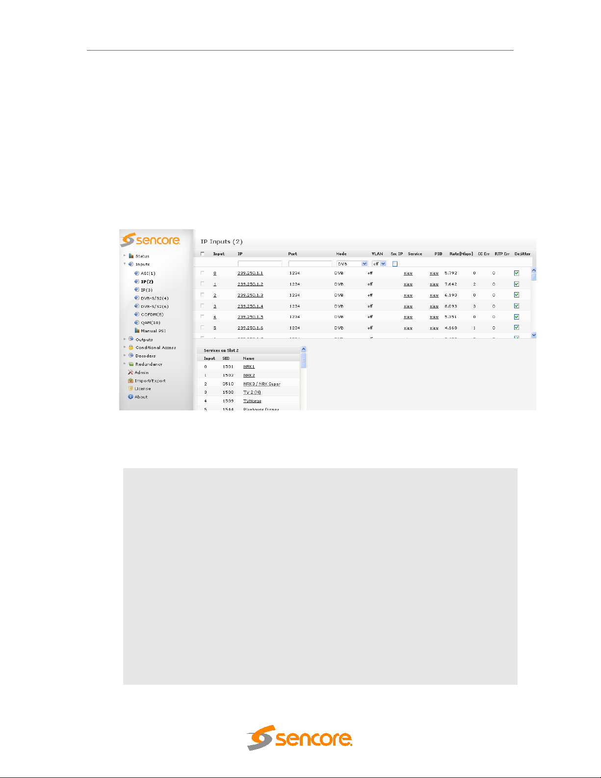
DMG 3200/3100/3000 – User Manual
o OFF
o Port by 2
5.4.5 IP Input
There are two different types of modules supporting IP input, the switch with IP module and the
standalone IP module (with and without FEC option). The following description is valid for all.
The input streams can be either SPTS (VBR or CBR mode) or MPTS. To configure the module:
• Switch to the Inputs node in the Navigation Pane
• Select the IP input module you want to c onf igure a nd the module configuratio n w indo w will be
displayed (see Figure 5.28). Services available on all inputs will be listed in this view.
Figure 5.28 - IP Input
When adding an IP input, the following parameters are available:
IP
Port
Src IP
Mode
Increment After a multicast is added, the current IP and Port values will be incremented
IP address corresponding to the input
Port corresponding to the input
Check to enable Source filtering (IGMPv3 / SSM)
Select one of the following:
o DVB
o MPEG
o ATSC
o DVB (SDT)
by one of the following:
o IP
o Port
Page 72 (306)
Page 73

DMG 3200/3100/3000 – User Manual
VLAN
The IP input window shows all configurab le settings as well as the current bitrate an d service
information. The following parameters are available:
Input
IP
Port
Rate [Mbps]
CC Err
RTP Err
Displays available VLANs; the default value is off.
Select a suitable VLAN if required.
Port on the IP input m odule – as signed autom atically when join ing a unicast
or multicast.
For Switch with IP modules, the Port A will use i nput num bers 0 to 249, Port
B will use input 1000 to 1249.
IP address of the multicast or unicast
Port of the multicast or unicast
Incoming data rate
Continuity Counter Error – indicates that one or more packets are lost
Real-time Protocol Error – represents the number of discontinuities on the
RTP counter if RTP is enabled on source. If RTP is not enabled on the
source, N/A is displayed.
Mode
De-Jitter
For IP input modules, clicking on the IP address under the IP column allows for the IP, Port,
Mode, Dejitter, Name, IGMPv3/SSM, and VLAN parameters to be edited.
The mode of the input stream.
Checking this check box activates the de-jitter algorithm on the input port.
Enabling this algorithm is recommended in order to achi eve the best results.
However, in some cases, if the input quality is very poor or missing PCR PID,
a better result may be achieved by disabling this feature. Note that the output
from the streamer will be very poor as well.
Page 73 (306)
Page 74
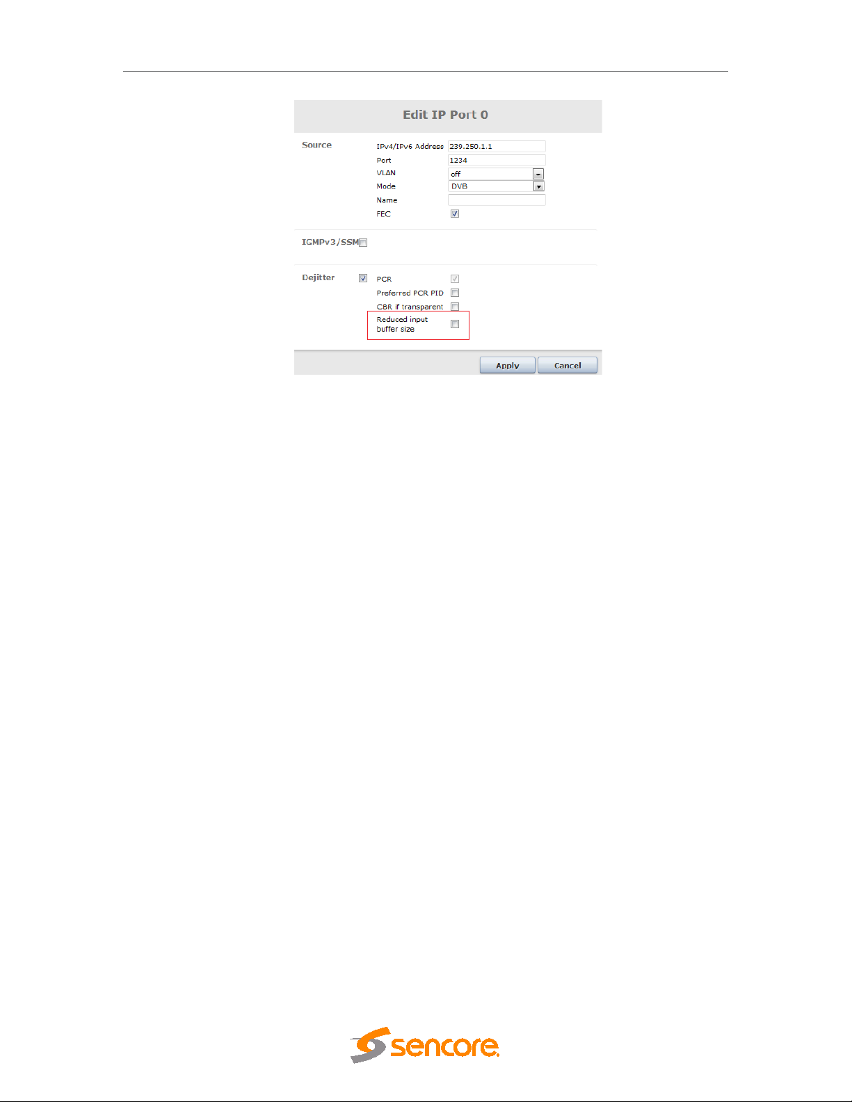
DMG 3200/3100/3000 – User Manual
Figure 5.29 - Edit IP Port
Page 74 (306)
Page 75

DMG 3200/3100/3000 – User Manual
The following additional parameters are available for configuration:
Name
IGMPv3/SSM
Dejitter
Reduced
Input Buffer
The status parameters for the IP module are shown in Figure 5.30 below.
This name is displayed as a toolt ip whe n the mouse cursor hovers over the
port.
Enable or disable IGMP v3/SSM on the port, Please see 5.4.5.3 for m ore
information and options
If input de-jittering is enabled, the following options are displayed:
o PCR. This is automatic for regular streams
o Preferred PCR PID. T his allows you to set a PCR PI D in the input
multiplex as a priority to use for de-jittering. If this PID is not
available, then the next valid detec ted PCR will be used. This is
only valid for transparently mapped streams.
o CBR (if transparent). This de-jitter mechanism will use the
incoming CBR total bitrate as a guide for the clock source of the
stream. This is only valid for transparent mapped and PID imported
outputs.
This feature is only available on the Switch+IP module.
Enable or disable Reduced Input Buffer for introducing a low latency IP
dejitter function on the Switch+IP and Dual IP modules.
The following parameters are available:
Sync
Effective Bitrate
Total Bitrate
Active Source
Page 75 (306)
Figure 5.30 - IP Input Port Status
Interval of the sync byte, usually 188
Effective bitrate of the input stream
Total bitrate of the input stream
IP address for the MPTS/SPTS source (Used for IGMP v3)
Page 76

DMG 3200/3100/3000 – User Manual
5.4.5.1 Setup of IPv6 input
The Switch+IP input module suppor ts IPv6 multicast and unicas t inputs. When using standar d
IPv6 address syntax (128 bits, ‘:’ instead of ‘.’), the G UI will interpret the address as an IPv6
address.
The VLAN setup is independent on the choice of IPv4 or IPv6.
Source IP address has to match the IP format used for the destination IP address.
5.4.5.2 Modification of input
The defined inputs m ay be modif ied to use another I P address. The new IP address m ay
be chosen freely between IPv4 and IPv6 addresses.
Figure 5.31 -Setup of IPv6 input
5.4.5.3 Source filtering on Switch IP input.
On the IP input, it is possible to use diff erent mechanisms in order to filter on the Source IP
address of the incoming multicast.
Source filtering (relevant where 1 source is specified) is only available in Switch+IP input cards .
Page 76 (306)
Page 77
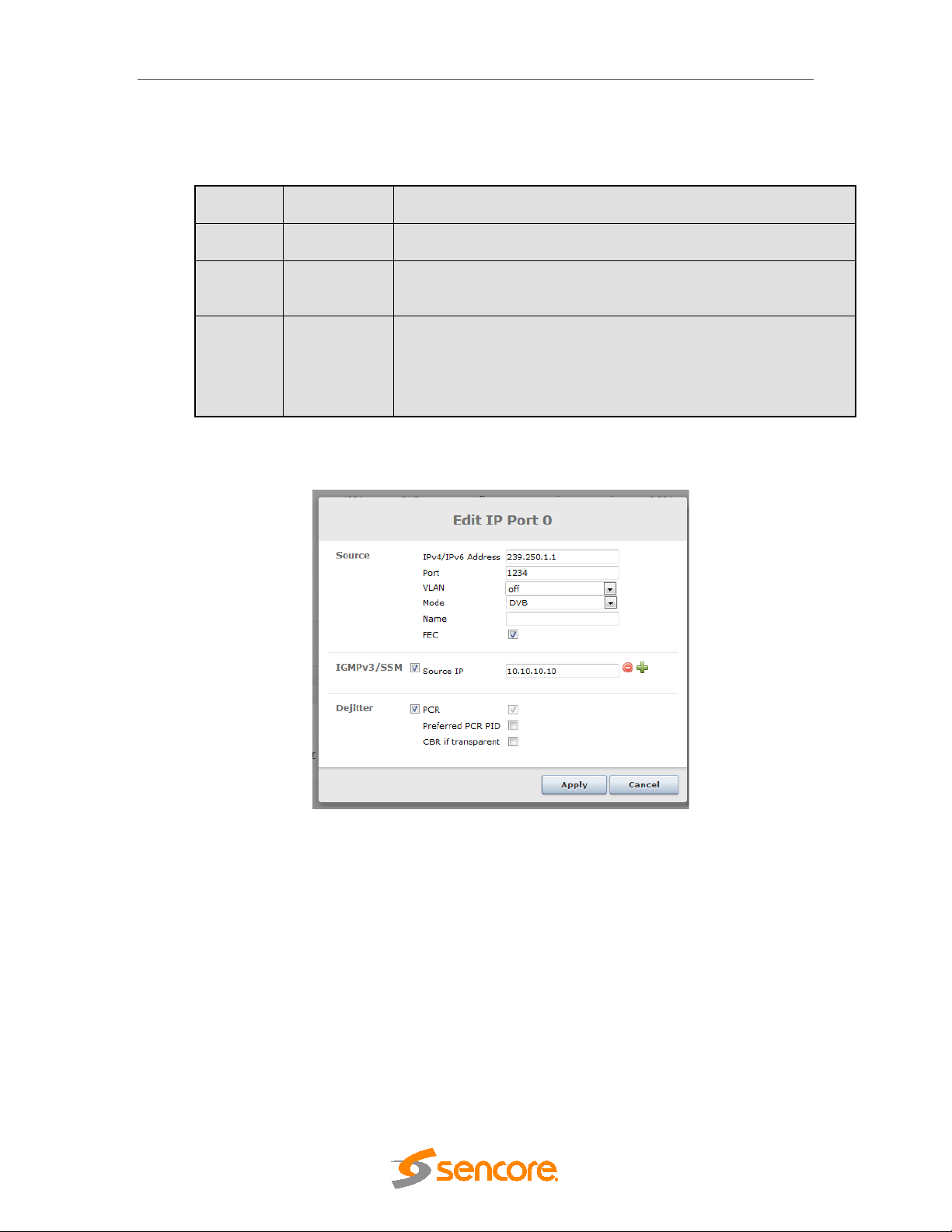
DMG 3200/3100/3000 – User Manual
Please note, only one of these sources should be active at a given
System behavior for different combinations of IGMP (version 2 or 3) input configurations:
Sources Source filter Comment
0 Off GUI has not enabled filtering and no source is specified.
1 On
>1 Off
IGMPv3/SSM Source filtering is shown in figure below
Only the multicast with t he matching source addres s is available on
the input. This does not require IGMPv3
In this mode all IGMP v3 s ou r ces ar e mapped to the same port. I.e. it
is not possible to reuse the MCAST:PORT pair on other inputs
time.
Figure 5.32 - Edit IP Port for IGMP source filtering
If it is required that multiple sources of the same multicast be enabled concurr ently, then these
will need to be subscribed to on unique input ports, each specifying their source IP address.
5.4.5.4 IP Input with FEC
For IP input modules w ith F EC, th e in put w indo w has an additional column with a c h eck box f or
each stream, allowing you to enable FEC.
Page 77 (306)
Page 78
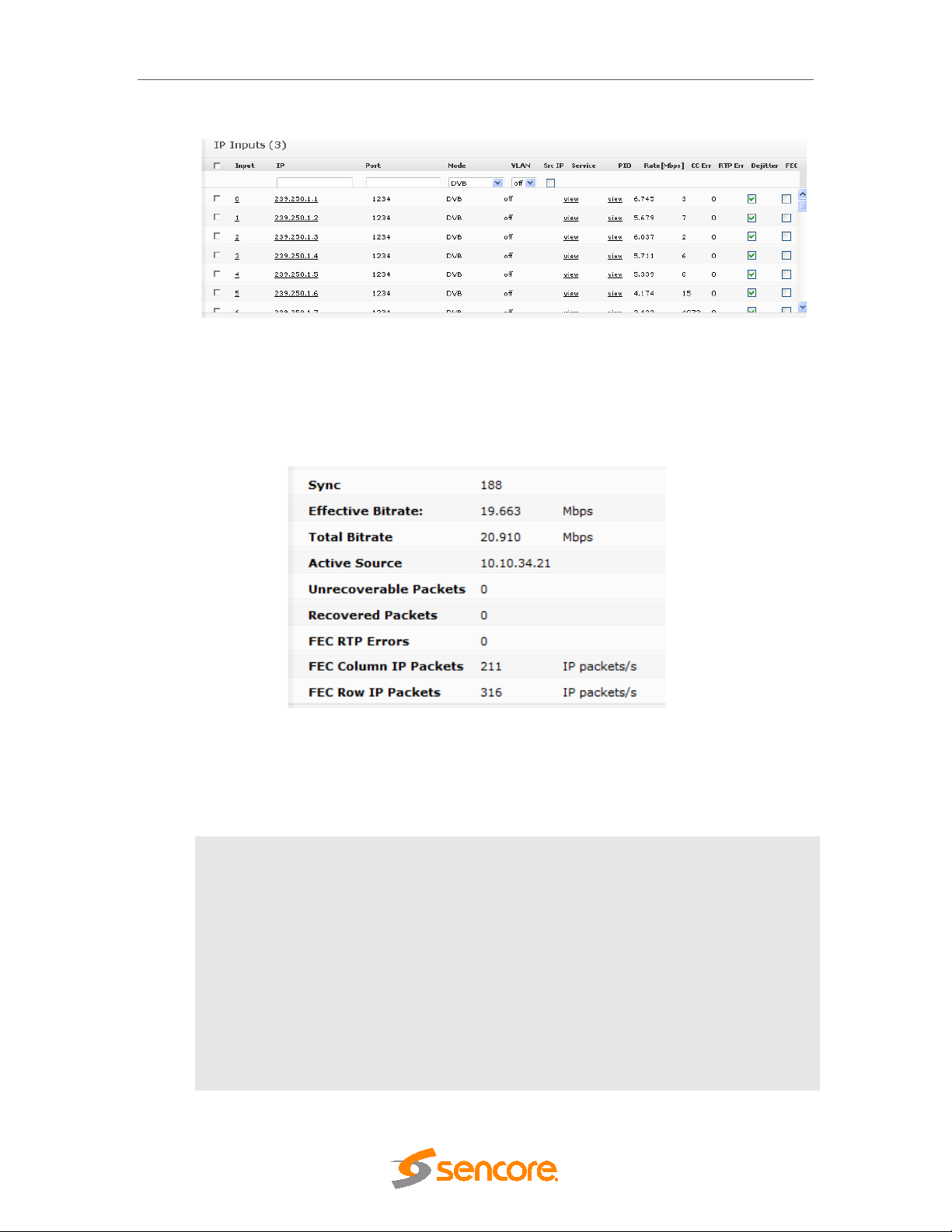
DMG 3200/3100/3000 – User Manual
Figure 5.33 - IP Input Page (for Modules with FEC)
For the IP input module with FEC there are additional status parameters are available, on top of
the generic Sync, Effective Bitrate, T otal Bitrate, and Active Source, as shown in Figure
5.34.
Figure 5.34- IP Input Port Status (for Modules with FEC)
The additional parameters are described in further detail below:
Unrecoverable
Packets
Recovered
Packets
FEC RTP Errors
FEC Column IP
Packets
FEC Row IP
Packets
Number of lost data packets that cannot be recovered with FEC
Number of data packets recovered with FEC
Number of missing FEC packets
Number of Column FEC packets per second (packet rate)
Number of Row FEC packets per second (packet rate)
Page 78 (306)
Page 79

DMG 3200/3100/3000 – User Manual
FEC Matrix Rows
(D)
FEC Matrix
Columns (L)
The combination of Unrecoverable Packets, Recovered Packets, and FEC RTP Errors is a
good indication of network quality.
Number of rows in the FEC matrix of the incoming stream
Number of columns in the FEC matrix of the incoming stream
5.4.5.5 Adding a New Input Stream
In the Input Control pane add the multicast/unicast I P address and por t. Click Add. The input
module will now issue an IGMP join request for the selected multicast and start to anal yze the
incoming stream. The service found on the selected multicast will be listed in the service view in
the lower part of the input page.
5.4.5.6 Removing a Multicast Input
Select the input to be removed by clicking on the check box on the left of the inp ut e ntry (in the
Existing IP Inputs pane).
Click the Remove button in the Remove section to remove a selected input.
Please note that you can only remove inputs that are currently not in use. To delete these
streams, the associated output service must first be removed/disabled.
5.4.5.7 T2MI De-encapsulation
The following additional information is displayed in edit option for Dual IP modules configured in
dip-t2mi-decap mode.
T2MIDe-encapsulation
T2MI PID
T2MI PLP
T2 de-encapsulation specifies to extract one PLP from T2MI stream
This is T2MI stream PID
This is T2MI stream PLP ID of the requires stream
Page 79 (306)
Page 80

DMG 3200/3100/3000 – User Manual
Figure 5.35- T2MI De-Encapsulation for IP Input configuration
Page 80 (306)
Page 81

DMG 3200/3100/3000 – User Manual
Slot
Slot position in the chassis
Type
Type of input module : ipswitch
Services
Number of services present in the transport stream
Effective Rate
Total bandwidth of the incoming transport streams.
CC Errors
Number of Continuity Counter (C C) errors detected on all input ports
TS Errors
Number of Transport Stream (T S) errors detected on all input ports.
RTP Errors
Real-time Transport Protocol sequence errors since last reset (applies
BP Rate
Rate of active services transmitted to the backplane
5.4.6 Seamless IP Input
The Seamless IP input module allows two input interfaces to be connected to different
network sources, but for the system, this is a single module. The same multicasts are
subscribed to on both interfaces. These multicasts must come from the same so urce.
All function and status nor mally associated with IP input cards are pres ent for the logical
module. In addition data rate, sequence errors, and relative delay for each stream are
reported for every input.
Moreover, alarms related to the network interface and stream alarms (e.g. “No bitrate”)
appear as warnings if the y occur onl y on a single inter fac e. “Link down on interf ace A or B”
is a major alarm . If alarms appear on both interfaces, they will act as for normal IP input
cards, and be a single alarm with the same alarm ID as used on other IP input cards.
The following information is displayed in status parameters for Seamless IP Input configuration:
Module
Input Rate
A and B both will be displayed.
Input Rate of active services for both A and B will be displayed.
since last reset; CC errors indicate that one or more packets are lost.
TS errors indicate problems with the incoming TS structure of the
streams
to both Port A and port B)
Figure–5.36 IP Input Seamless module Status Parameter view
Page 81 (306)
Page 82

DMG 3200/3100/3000 – User Manual
Seamless Relative delay
Seamless relative delay in ms will be displayed.
Active source
Source IP address
Input Bitrate
Source Input Bitrate in Mbps.
Sequence Protocol
Seamless protocol in use, either RTP or UDP.
Sequence Errors
Source sequence errors since last reset
Port Status
Either Master or Slave depending on which is the main port
Figure–5.37 IP Input Seamless module Status Parameter detailed view.
Additional status parameters for IP Input seamless module:
Page 82 (306)
Page 83

DMG 3200/3100/3000 – User Manual
5.4.6.1 Unique Configuration of input ports
IP settings can be configured different on the two IP ports in Seamless Input mode. If required
to be different from port A, the checkbox can be enabled and the new parameter entered.
Enabled
IP
Port
Source Port
Source IP
VLAN
Figure - 5.38 Unique configurations on two ports.
Specify that which Port is enabled.
IP address of the Port A and Port B
IP port number
The IP source port of the output multicast
The source IP address override feature allows configuration of the
source address of an IP output multicast or unicast to any IP address.
Displays available VLANs; the default value is off.
Select a suitable VLAN if required.
Page 83 (306)
Page 84

DMG 3200/3100/3000 – User Manual
5.4.6.2 Non-Syncronized Inputs
With the Seamless IP Input module, it is possible to configure two non-s ynchronized multicasts.
In this mode it is required to enable the ‘Filter input synch ronization’ option f or the port in order
to filter the normally present alarm.
In this mode, the behavior differs from the Seamless IP mode in that the current source will
switch if there is a 100ms with 0 bitrate on the input multicast.
More details on this can be found in Chapter 12.1.5.
5.4.7 Dual IP Input
The Dual IP input module allows two individual input interfaces to be connected to network
sources, but for the s ystem, this is exactly as two IP input cards. The input streams can be
either SPTS (VBR or CBR mode) or MPTS. to configure the module.
All function and status normall y associated with IP input cards are pr esent for the module but
the total Inp ut Bitrate for bot h IP ports cannot exc eed 850 Mbps or 250 servic es, ie the limit is
shared between the two ports.
An alarm (“Back-plane bitrate exceeded. Pack et dropped.”) will be raised when the 850Mbps
backplane limitation is exceeded.
Figure - 5.41 Dual IP Input Configurations
Page 84 (306)
Page 85

5.4.8 8VSB Input
The 8VSB input m odule can r eceive up to f our individual 8VSB input streams. To configure the
module:
• Switch to the Inputs node in the Navigation Pane
• Select the 8VSB module you want to configure to display the module configuration (see
Figure 5.42). Services available on all four 8VSB input ports will be listed in this view.
DMG 3200/3100/3000 – User Manual
Figure 5.42- 8VSB Input
The 8VSB input window shows all configurable settings as well as the current bitrate and
service information. The following parameters are available:
Input
Rate [Mbps]
CC Err
Mode
Port on the 8VSB input module
Incoming data rate
Continuity Counter Error – indicates that one or more pack ets are
lost
Select one of the following modes:
o DVB
o ATSC
o MPEG
o No PSI analysis
The default mode is AT SC. I f t he incoming transport stream is not
ATSC compliant, use MPEG mode instead.
Freq[MHz]
Enable
Page 85 (306)
Specify the currently tuned frequenc y in MHz, valid range is 47 –
861MHz.
Enable the corresponding input port
Page 86

DMG 3200/3100/3000 – User Manual
To monitor any of the demodulated 8VSB input signa ls, one of the 8VSB input ports can be
assigned to the output ASI monitor inter face. The demodulated 8VSB input sign al will then be
copied onto the monitor port for further analyzing or m onitor ing of the trans port str eam . Normal
operation will not be affected if the monitoring port is used.
The status parameters for the 8VSB module are shown in below. Click on the letter
representing in the input channel (A, B, C or D) to dis play the status parameters for the specif ic
input port.
Figure 5.43- 8VSB Status View
The following information is displayed:
Sync
Effective Bitrate
Total Bitrate
Lock Status
Level
MER
MPEG sync number: 188 or 204
Effective bitrate of the input stream
Total bitrate of the input stream
Lock status of the tuner
RF level measured in dBmV
Modulation Error Radio in d B - a typical g ood reading is between
30 and 40 (the higher the better).
5.4.9 QAM-B Input
The QAM-B input module ca n rec eive up to four individual QAM-B input streams. To configure
the module:
• Switch to the Inputs node in the Navigation Pane
• Select the QAM-B module you want to configure to display the module configuration .Services
available on all four QAM-B input ports will be listed in this view.
Page 86 (306)
Page 87
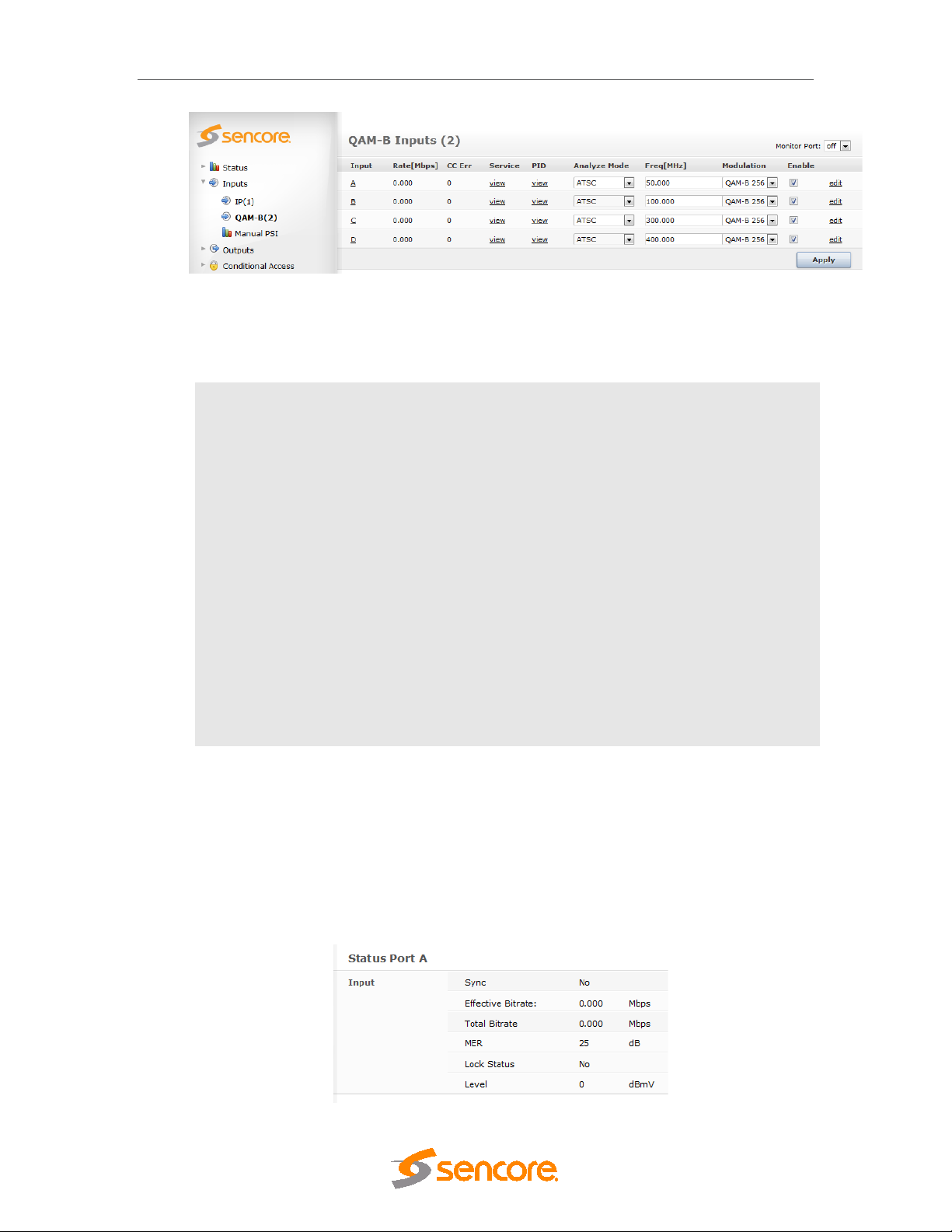
DMG 3200/3100/3000 – User Manual
Figure 5.44 – QAM-B Input
The QAM-B input window shows all configurable settings as well as the current bitrate and
service information. The following parameters are available:
Input
Rate [Mbps]
CC Err
Mode
Freq[MHz]
Enable
To monitor any of the demodulated QAM-B input signals, one of the QAM-B input ports can be
assigned to the output ASI monitor interface. The demodulated QAM-B input signal will then be
copied onto the monitor port for further analyzing or m onitor ing of the tr ansport s tream . Normal
operation will not be affected if the monitoring port is used.
Port on the QAM-B input module
Incoming data rate
Continuity Counter Error – indicates that one or more packets are lost
Select one of the following modes:
o DVB
o ATSC
o MPEG
o No PSI analysis
The default mode is ATSC. If the incoming transport stream is not ATSC
compliant, use MPEG mode instead.
Specify the currently tuned frequency in MHz, valid range is 47 –
861MHz.
Enable the corresponding input port
The status parameters for the QAM-B module are shown in below. Click on the letter
representing in the input channel (A, B, C or D) to dis play the status parameters for the specif ic
input port.
Page 87 (306)
Page 88

DMG 3200/3100/3000 – User Manual
Figure 5.45 – QAM-B Status View
The following information is displayed:
Sync
Effective Bitrate
Total Bitrate
Lock Status
Level
MER
MPEG sync number: 188 or 204
Effective bitrate of the input stream
Total bitrate of the input stream
Lock status of the tuner
RF level measured in dBmV
Modulation Error Radio in dB - a typical good reading is between 30
and 40 (the higher the better).
5.4.10 DVB-T2 Input
The DVB-T2 input module can receive up to four individual Frequencies. It comes in two
different HW configurations. One version has a single input connector that is distributed to the 4
demodulators internally while the second version has 4 input connectors; one for each tuner. To
configure the module:
• Switch to the Inputs node in the Navigation Pane
• Select the DVB-T2 module you want to configure to display the module configuration (see
Figure below). Services availabl e on all four DVB-T2 input ports will be listed in this view for
each port type.
• Supports PLP input selection. Note that in multi PLP environment it can only tune one PLP at a
time.
Figure 5.46- DVB-T2 Input
The DVB-T/T2 mode shows all m ajor configuration settings as well as the curr ent bitrate and
service information. The following parameters are available:
Page 88 (306)
Page 89

DMG 3200/3100/3000 – User Manual
DVB-T2
Input
Rate [Mbps]
CC Error
Service
PID
Mode
Modulation
Frequency
Port on the DVB-T2 input module
Incoming data rate
Number of Continuit y Counter (CC) err ors detected on all input ports
since last reset.
CC errors indicate that one or more packets are lost.
Number of services present in the transport stream
Listing all input PIDs for each input.
The mode of the input stream , either:
o DVB
o MPEG
o ATSC
o DVB (SDT)
o OFF
Select any of the following modes.
• DVB-T
•
Specify the DVB-T/T2 frequency in MHz, valid range is 42 – 870Mhz.
Bandwidth [MHz]
Spectral Inv.
PLP ID
Enable
The above list of parameters can be conf igured by clicking on the edit link to the right of each
input. The pop up dialog below will be displayed:
Specify the bandwidth, select from 6, 7, or 8MHz
New T2 Module can specify the bandwidth 5, 6, 7, or 8 Mhz.
Checking this check box activates the spectral Inversion.
Specify the PLP from the input.
Enable the corresponding input port.
Page 89 (306)
Page 90

DMG 3200/3100/3000 – User Manual
Figure 5.47 – DVB-T/ Input Port Configuration
Name
The status parameters for the DVB-T/T2 module are shown in the figure belo w. Click on the
letter repr esenting the input channel (A, B, C or D) to display the status parameters for the
specific input port.
This parameter allows for each port in a module to be labeled. This label is
visible as a tooltip when the mouse cursor hovers over the port. Port
names are shown in the alarms when a non-empty string is set as the
name..
Figure 5.48 – DVB-T Status Parameter view
Page 90 (306)
Page 91

DMG 3200/3100/3000 – User Manual
The following information is displayed in status parameters for DVB-T/T2:
Locked Status
Effective Bitrate
Total Bitrate
Modulation Error
Rate
Signal Noise
Ratio
Pre-Viterbi BER
Pre-RS BER
Hierarchy
FFT Mode
Guard Interval
Constellation
Code rate
Lock status of the tuner
Effective bitrate of the input stream
Total bitrate of the input stream
Modulation Error Radio in dB - a typical good reading is between 30
and 40 (the higher the better).
Signal to Noise Ratio – represents how much the signal has been
corrupted by noise.
Bit error rate before Viterbi error correction.
Bit error rate after Viterbi / before Reed Solomon error correction
Hierarchy of the currently tuned channel.
Fast Fourier Transform Mode of the currently tuned channel.
Guard Interval of the currently tuned channel.
Constellation of the currently tuned channel.
Code rate of the currently tuned channel
Page 91 (306)
Figure–5.49 DVB-T2 Status Parameter view
Page 92

DMG 3200/3100/3000 – User Manual
Additional status parameters for DVB-T2 demodulation:
Pre LTPC BER
Pre BCH BER
Number of PLPs
PLP Id
Rotated Constellation
FEC
Bit error rate before LDPC error correction
Bit error rate after LDPC / bef ore BCH err or correc tion, should <10
7.
Specify the count of PLPs
Specify the PLP Id
Rotated Constellation of the currently tuned channel.
Forward Error Correction.
6 Conditional Access Configuration
The unit supports descrambling and scrambling given that the required modules have been
installed. Descrambling and scrambling are processing elements; hence they are not listed in
the Input or Output nodes. These functions are found as part of the output service
configuration.
-
The Conditional A cce ss node displays existing configuration for CAMs, SCSs, Scramblers
and Descramblers.
The following parameters are available:
CAM:
Services
Page 92 (306)
Figure 6.1 - Conditional Access Node
Number of services being descrambled by the CAM
Page 93

DMG 3200/3100/3000 – User Manual
CAM Name
PIDs
Input Bitrate
Output Bitrte
Scramblers:
Algorithm
Descramblers:
Algorithm
Select the correct algorithm to be used for bulk descrambling based on the
currently installed licenses.
If you feel your chosen algorithm is missing, please contact Sencore support.
Name/provider of CAM module
Number of PIDs currently being descrambled
Input bitrate into the CAM module
Output bitrate from the CAM module
Select the correct algorithm to be used for Scrambling based on the currently
installed licenses.
If you feel your chosen algorithm is missing, please contact Sencore support.
Page 93 (306)
Page 94

DMG 3200/3100/3000 – User Manual
6.1 Descrambling – Common Interface Module
The unit is capable of descrambling a number of incoming services with the installation of a
descrambler module. The descrambler module comes with two Common Interface slots and
can therefore host two Conditional Access Modules (CAM’s). Each Common Interface slot
supports the descrambling of one or more services depending on the CAM module used.
6.1.1 Descrambling a Servi c e
To descramble a service first insert the CAM into an available Common Interface slot, then
insert your Smart Card into the CAM.
To assign the Common Interface slot to a service to be descrambled, double click on that
service and within the Outputs page to display the Service Properties dialog (Figure 6.2).
Figure 6.2 - CAM Configuration within the Service Properties Dialog
6.1.2 Transporting a Descrambled Service to Multiple Output Modules/Ports
A descrambled service may be sent to up to four individual outputs. In other words, if the unit is
configured with an IP output module and a QAM output module, then the descrambler module
will be able to copy the descrambled service and send it to both the IP output and QAM output
destinations. Alternatively, the same service can be sent to different ports on the same output
module.
When an input service is configured to be sent to different outputs, the configuration is
automatically performed by the system – as long as the same descrambler is selected. This
copy function is based on per service, i.e. if a Smart Card is able to descramble up to 10
services, then the maximum number of output streams from the descrambler will be 40 (10 x
4).
6.1.3 CAM Configuration
The CAM configuration page below (accessible by selecting Conditional Acces s CAM in
the Navigation Pane) displays the following:
Page 94 (306)
Page 95
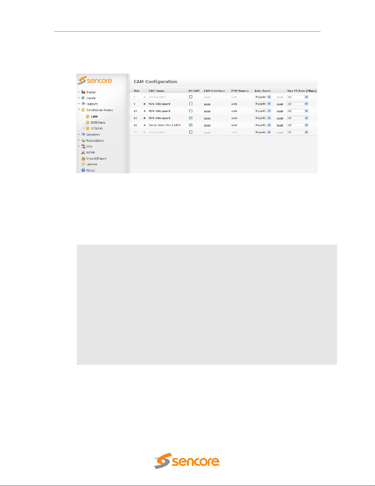
DMG 3200/3100/3000 – User Manual
• A list of available CAM modules with its corresponding name,
• The chassis slot where the Descrambler module is installed, and
• The CAM slot (each Descrambler module has two CAM slots labeled A and B).
Figure 6.3 - CAM Configuration Page
If there is no CAM module in the Descrambler module, CAM Name will be displayed as not
available.
The Alt CAM Mode, CAM Interface, EMM Source, Auto Reset, Reset and Max TS Rate are
the configuration fields available in this page (Figure above).
Slot
CAM Slot
CAM Name
Alt CAM Mode
CAM Interface
EMM Source Displays the source of the EMM, the default value is auto.
Slot in which the Descrambler is installed
Slot in which the CAM module is installed – either slot A or B
Name of the CAM module
Activate sending of the entire input stream to the CAM without PID
filtering - explained in detail in Section 6.1.4.
Displays the menu defined by the CAM manufacturer – explained in
detail in Section 6.1.5.
Page 95 (306)
Page 96

DMG 3200/3100/3000 – User Manual
Auto Reset
Man Reset
MAX TS rate
[Mbps]
Automatic CAM Reset – enables the CAM to reset if there are failures in
the descrambling process. This helps the CAM to recover automatically
without requiring the user to reset manually. Auto Reset provides the
following options:
Off – automatic reset is disabled; the CAM can be reset manually.
One – if one or more services have descrambling failures, the CAM will
reset.
Majority – if more than half the services configured to be descrambled in
the CAM fail, the CAM will reset.
All – in this mode, the CAM will simply reset if all services configured in
the CAM fail to be descrambled.
Manual CAM Reset – sometimes resetting the CAM Module is
necessary, e.g. if the CAM is not responding. Click reset to power
recycle the CAM module.
Maximum Transport Stream Range can be used if the rate of the
transponder exceeds the default CAM input rate. The user can choose
one of three values:
• 43 Mbps
• 58 Mbps
• 68 Mbps
6.1.4 Alt CAM Mode
In a normal configuration, when an input stream is sent to the CAM, only a selection of PIDs
that comprise the services being descrambled are actually transmitted, together with CArelated PIDs listed in the PSI.
In Alt CAM Mode, the entire input stream is sent to the CAM without PID filtering. This feature
can be useful in the following scenarios:
Some CA systems do not list all the required PIDs in the PSI. Often this will involve the EMM
PIDs, resulting in problems keeping the subscription updated over time. Alt CAM Mode can
prevent this problem.
Sending all the PIDs changes the packet timing of data streaming into the CAM to more
closely resemble that of the input. Testing has shown that very few CAMs require this to work
reliably over time.
Not filtering PIDs sent to the CAM simplifies the input card configuration due to all input PIDs
being sent. This may slightly improve response time on service changes. The effect may be
marginal, but it could be of value, especially for inputs where most of the services are
descrambled in the same CAM anyway.
The default value is 43; however, not all CAMs support these rates.
The drawback of Alt CA M Mode is increased bandwidth usage from the input card(s) into the
system. In most systems, this is not a significant limitation; however, it should be taken into
consideration for large systems.
Page 96 (306)
Page 97

It is generally advised to disable Alt CAM Mode as this creates a higher bandwidth
requirement in the unit.
We recommend you enable this option if you have problems with:
o descrambling a service
o keeping the subscription updated reliability
6.1.5 CAM Interface
Each CAM Module has its own menu structure defined by its manufacturer to access module
information, e.g. subscription status and to insert configuration data, e.g. a new PIN Code,
maturity rate, and a key to descramble a service.
The CAM Interface feature allows operators to access and interact with these menus
easily via the web GUI. By clicking on Open under the CAM Interface column, a pop-up
box appears over the C A M Configuration page. This is the CAM Interface dialog.
6.1.6 Navigation
DMG 3200/3100/3000 – User Manual
Based on Figure 6.1, the standard CAM Interface provides two buttons at the bottom and
a list of clickable menu options.
• The Back/Exit button returns to the previous menu
• If the Back/Exit button is pressed on a top-level menu, the same menu screen
will be displayed
• The Close button stops interaction with the CAM Module, closes the CAM
Interface dialog, and displays the CAM Configuration page
Figure 6.5 - Example of a Menu from Conax
It is possible that the dialog above varies depending on the CAM manufacturer. Menus
that do not allow user interaction are called Lists. Since Lists are bottom-level menu
items, possible operations are either to go back to the previous menu or close the CAM
Interface.
Page 97 (306)
Page 98
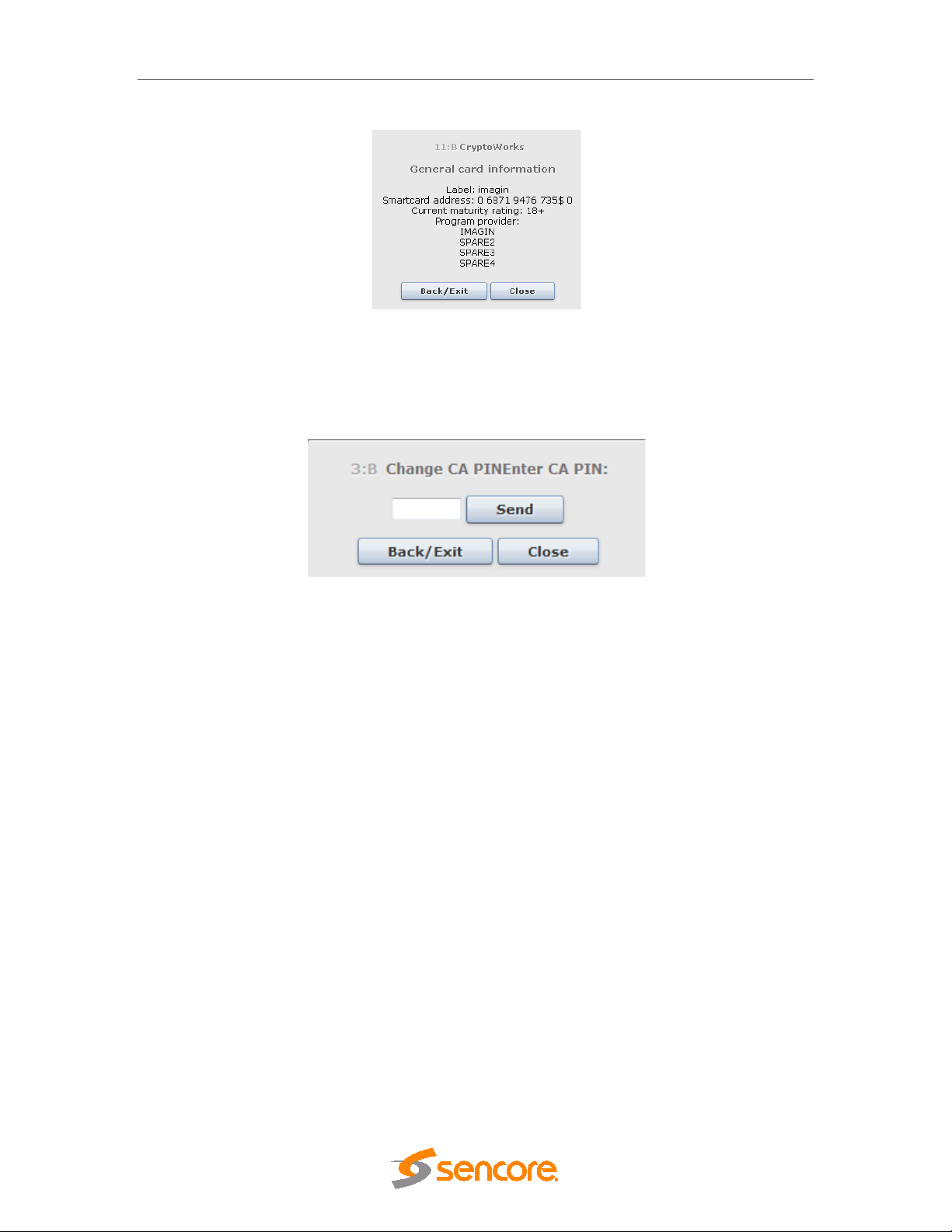
DMG 3200/3100/3000 – User Manual
Figure 6.6 - Example of List from CryptoWorks
Another type of dialog is the Enqu iry dialog (
the CAM Module requires us er input suc h as a PIN code. The CAM defines the max imum
length of the input data and whether actual characters are displayed as the user types.
Figure 6.7 - Example of Enquiry
6.1.6.1 Multiple Users and CAM access
The CAM Interface supports multiple users but not multiple sessions. This means that it
is possible to access the CAM Interface of the same CAM Module from different
computers or browsers simultaneously, but users cannot be on different levels of the
menu. For this reason the CAM Interface is refreshed every 10 seconds to request the
current valid menu screen.
Due to this synchronization scheme the menu screen will change for all current users
even if just one of them interacts with the CAM Interface dialog.
Multiple users interacting with a single CAM Module can lead to synchronization errors.
For instance, when one user tries to access a menu that has not been refreshed after
another user has interacted with it, a synchronization error will occur. This will display a
Status error. This and other errors are handled by the CAM Interface to provide safe
and consistent interaction.
Figure 6.7). This dialog is displayed when
Page 98 (306)
Page 99

6.1.7 Error Handling
When a situation results in an error and does not permit proper communication with the
CAM Module, an error message will be displayed. There are different conditions that can
lead to errors. Table 1 lists the possible error messages and their descriptions.
Error Message Description
DMG 3200/3100/3000 – User Manual
Error: No session.
Refresh to recover
communication
Error: Session ID.
Refresh to recover
communication.
Error: Status. Refresh
to recover
communication.
Error: Invalid message
format.
Error: CAM No
response. Refresh to
recover
communication.
No CAM/PC Card in
slot.
CAM not identified, or
identified as non-CAM.
The user is trying to answer a menu or enquiry and the s ession has
been closed.
The user is trying to access a session that is no longer available.
The status count value received from GUI is not the same as the one
in the CAM Interface. T his means that the GUI could be in another
level of the menu which can lead to a non desired operation.
The message parsing process is not successful.
Within a specified timeout, the CAM Interface failed to respond.
There is no CAM Card in the slot.
The PC Card is not identified, or identified as non-CAM.
Table 2 - Error Messages and th eir Des cripti ons
When an error message is displayed, the Back/Exit button is replaced by Refresh. The
operator can either close the CAM Interface, or try to Refresh the session. If a
synchronization error occurs, Refresh is the ideal solution. Otherwise, the operator can
wait for the CAM Interface to request a Refresh automatically.
Page 99 (306)
Page 100

DMG 3200/3100/3000 – User Manual
6.2 Bulk Descrambling
Sencore’s bulk descrambler is able to descramble up to 250 services per card. Actual
descrambling is performed in firmware while extraction of the Control Word from the ECMs is
done by integrated soft clients provided by the CA vendors. The bulk descrambler runs on a
dedicated module, providing an external Ethernet port used for the communication between the
soft client and the CA server for exchange of access criteria.
The maximum number of ECMs that can be descrambled depends on the processing power
requirement of the CA client.
Currently the descrambler algorithms supported are: DVB-CSA or AES-ECB; but not both
simultaneously.
Below are the CA systems integrated with the bulk descrambler module:
CA System Number of Services Supported
BISS 250 services
Latens 250 services
Verimatrix 250 services
Preparing the bulk descrambler module to descramble services requires some initial
configuration to establish a link to the CA vendor’s server. To be able to view the GUI and enter
necessary parameters, the correct licenses must be installed as the bulk descrambler
functionality is licensed together with the number of services.
Figure 6.8 - Setting up the Bulk Descrambler Module
Page 100 (306)
 Loading...