

Page 1
: INSTRUCTION MANUAL
For The
CG126 COLOR GENERATOR
Page 2
INSTRUCTION MANUAL
for the
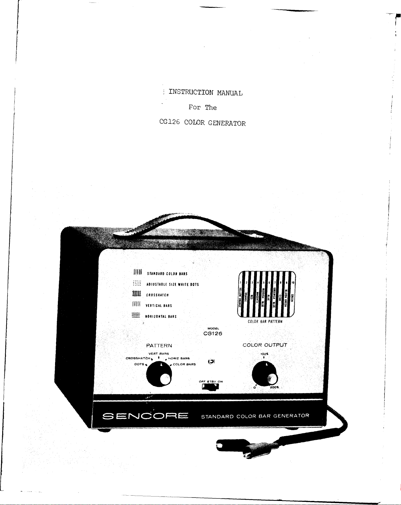
CG126 COLOR GENERATOR
Recognizing the need for a stable, low cost generator that produces
all necessary patterns for accurate convergence and trouble shooting in
the home, SENCORE has developed the CG126 Standard Color Bar Generator.
The CG126 is the smallest, lightest, and least expensive generator
of any on the market and yet it provides the same stable patterns of
generators costing twice as much. The CG126 provides the following
patterns:
Ten Standard Color Bars: The type and phase that is fast becoming the
standard of the industry. Crystal controlled keyed bars (RCA type with
30 degrees phase change between each) as explained in most service lit
erature, offer a complete gamut of colors for every color circuit test.
Adjustable Size White Dots: New stabilized dots, a must for convergence,
are created by new SENCORE counting circuits. The size of the dots are
adjustable from the rear of the unit.
Crosshatch Pattern: A basic requirement for fast CRT convergence, and,
also, for sweep linearity and "overscan" adjustments.
Vertical and Horizontal Bars: An added feature to speed up convergence,
not found on many other color generators.
SPECIFICATIONS
RF Output: Frequency i s factory set to Channel 4 . It can easily be
changed to Channel 3 or Channel 5, if Channel 4 is used in your
area.
Modulation: Any one of five patterns: Color Bars, Dots, Crosshatch,
Vertical Bars, or Horizontal Bars.
Tube Complement: 6-12AU7A, 2-12AZ7, 1-12BE6
Diode Complement: 2-1N295
Crystal Complement: 1-189KC t .005% for timer, 1-3563.795KC ί .001%
for color Lars.
Power Consumption: 35 watts at 117 VAC line .
Size: 11 inches wide by 8 inches high by 6 inches deep.
Net Weight: 9 1/2 pounds.
CONTROLS ON THE CG126
The CG126 is an extremely easy generator to set up and use. Only three
front panel controls are needed in normal use. These are the AC power switch,
the Pattern switch and the Color Output control. Additional adjustments for
the timing circuits, and for dot size, are available on the rear of the unit,
but these are all factory set and normally do not need to be changed.
2
Page 3
AC Power Switch: The AC power switch is used to turn the unit ON and OFF.
It also has a middle STANDBY position which is used whenever you wish to
disable the pattern and RF carrier, but still keep the tube filaments hot
for instant use.
Pattern Switch: The pattern switch selects one of the five patterns avail
able to modulate the RF carrier. Composite sync is fed to the modulator at
all times s o that the patterns will not jump or fall out of sync when
switching from one pattern to another. The following patterns are available
on the CG126, each for a specific function.
1. Dots - There are 117 small size dots available, primarily for DC
convergence. A color TV set that is properly converged will have
white dots in the center of the picture tube (all three guns hit
ting the same spot on the CRT). Static (or DC) convergence is
controlled by the 3 small magnets spaced at 120 degrees around
the neck of the color CRT plus the blue lateral positioning magnet.
2. Crosshatch - In the crosshatch position, 9 vertical and 13 hori
zontal visible bars are generated. The crosshatch pattern is used
for dynamic convergence adjustments, overscan adjustments (height
and width) and for linearity adjustments.
3 . Vertical Bars - Nine vertical bars are generated in the vertical
bar position. These are used primarily when adjusting the dynamic
vertical convergence controls.
4 . Horizontal Bars - Thirteen horizontal bars are provided and are
used primarily when adjusting the dynamic horizontal convergence
controls.
5. Color Bars - Ten color bars are generated for color alignment and
trouble shooting in the color circuits of the TV receiver. The
color output is controlled with a separate control. The colors
which would be displayed on a normal color set are shown on the
upper right of the panel.
Color Output Control: The color output control changes the amount of color
signal that is fed to the modulator. It is used primarily to check the color
sync abilities of the receiver. A setting of 100 percent is normal. With
most receivers, the control can be turned to almost zero percent before the
set will lose color sync. This i s indicated by diagonal bands of color
(barber pole effect) within each color bar .
The 200 percent setting of the control is used to force a defective
set to sync while trouble shooting.
OPERATING THE CG126
To use the CG126, plug the AC cord into a 117V AC outlet, turn the
unit on and let the generator warm up for approximately 10 minutes. Connect
the output cable to the antenna terminals of the TV set . Tune the TV set to
Channel 4, or to the same channel as the CG126 i f the CG126 has been reset
3
Page 4
to some other channel.
Turn the pattern switch to the desired pattern.
Sharp, well defined patterns are necessary for convergence adjust
ments and for trouble shooting. Since the settings of the TV controls
will affect the quality and sharpness of the patterns produced by the
CG126, we will discuss briefly how these TV controls should be set. In
all of the following steps, the CG126 is on and the output cable is con
nected to the TV antenna terminals. The TV is set to Channel 4 .
Fine Tuning - Turn the CG126 to color bars and adjust the TV fine tuning
control for sharp, clear bars with a minimum of smearing on the edges.
This is the best tuning point for the TV and the control should be left
at this setting for all black and white patterns, also.
Occasionally, however, a higher dot contrast range (dot brightness
versus background) can be achieved by mistuning the TV slightly to favor
the dot frequency.
Contrast and Brightness Controls - Since the CG126 has a minimum amount
of background "hash" on any of the patterns, the settings of the contrast
and brightness controls can be set to your liking. However, for conver
gence adjustments it is desirable to have a high contrast between the
pattern and the background level in which case the contrast control should
be turned to near maximum.
When viewing color bars it is sometimes desirable to eliminate the Y
signal completely by turning the contrast control to zero.
Vertical Hold - All color TV sets have vertical retrace blanking. If the
vertical hold is not adjusted properly, retrace lines can be seen in the
upper part of the picture. Adjust the vertical hold control for the mini
mum number of retrace lines consistent with good vertical hold.
Horizontal Hold - On some sets there may be a slight "fanning" at the top
of the picture of all vertical lines in the pattern if the horizontal hold
control is not adjusted properly. These can be virtually eliminated by
adjusting the horizontal hold control. A high contrast setting may also
cause this effect.
SETTING UP AND TROUBLE SHOOTING COLOR TV WITH THE CG126.
Setting up and trouble shooting color TV is easy with the CG126. In
addition to a good generator, however, an established procedure should be
followed so that time will not be wasted in following misleading conditions.
We like to think of color TV trouble shooting as a three step approach.
The first step is to be sure that the color CRT and associated circuits
are operating properly. This involves checking for purity and convergence.
The second step in the procedure is to get a good black and white picture.
If the trouble is not solved by the first two steps then it must be in the
color circuits which brings up the third step of trouble-shooting the color
section of the receiver
4
Page 5
Let’s see how this works with the following example. If a color set
is tilted on its side or even tilted up as little as 30 degrees the purity
of the CRT will go off (the electron beams from each gun will hit all three
colors of phospher dots instead of just their own color). Under this
condition the black and white patterns from the CG126 (do t s, crosshatch etc.)
will look quite presentable and you may not even be able to detect anything
as being wrong. However, if you switch to color bars, the colors will be
strange or completely gone and your first impression would be to start
analyzing the color circuits. Thus, you can see the importance of checking
for proper purity and convergence first.
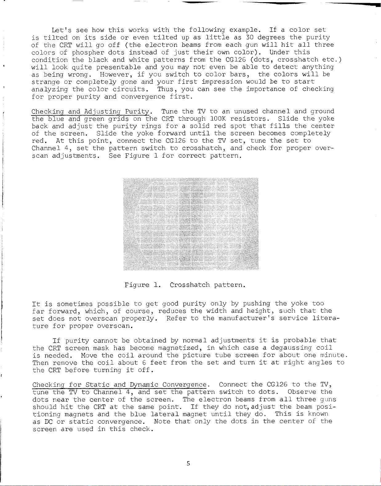
Checking and Adjusting Purity. Tune the TV to an unused channel and ground
the blue and green grids on the CRT through 100K resistors. Slide the yoke
back and adjust the purity rings for a solid red spot that fills the center
of the screen. Slide the yoke forward until the screen becomes completely
red. At this point, connect the CG126 to the TV set, tune the set to
Channel 4, set the pattern switch to crosshatch, and check for proper over
scan adjustments. See Figure 1 for correct pattern.
Figure 1. Crosshatch pattern.
It is sometimes possible to get good purity only by pushing the yoke too
far forward, which, of course, reduces the width and height, such that the
set does not overscan properly. Refer to the manufacturer’ s service litera
ture for proper overscan.
If purity cannot be obtained by normal adjustments it is probable that
the CRT screen mask has become magnetized, in which case a degaussing coil
is needed. Move the coil around the picture tube screen for about one minute.
Then remove the coil about 6 feet from the set and turn it at right angles to
the CRT before turning it off.
Checking for Static and Dynamic Convergence. Connect the CG126 to the TV,
tune the TV to Channel 4, and set the pattern switch to dots. Observe the
dots near the center of the screen. The electron beams from all three guns
should hit the CRT at the same point. If they do not, adjust the beam posi
tioning magnets and the blue lateral magnet until they do. This i s known
as DC or static convergence. Note that only the dots in the center of the
screen are used in this check.
5
Page 6
For dynamic convergence the crosshatch, vertical bar and horizontal
bar patterns are used. Dynamic convergence procedures are slightly dif
ferent for each color set and to make these adjustments to specifications,
the service literature for the set should be followed.
The second part of the procedure is to check all of the circuits which
will affect the black and white picture. These circuits in color TV sets
do not differ appreciably from the circuits found in black and white sets
except for an additional group of controls used for black and white track
ing adjustments. This group consists of separate controls for the screen
voltage on each CRT gun plus a B gain, G gain and a CRT bias control. In
older sets "background" controls took the place of the B gain, G gain and
CRT bias controls.
To adjust these controls you should refer to service literature for
the set, but basically the screen controls are adjusted for equal intensity
of each color whereas the B gain, G gain and CRT bias controls are adjusted
for the best black and white picture, throughout the normal range of the TV
brightness and contrast controls.
Other slight differences in color TV circuits are a regulated high
voltage supply to reduce blooming and loss of convergence, a separate focus
voltage supply and a wider IF response to pass the color information.
If the CRT is functioning properly and a good black and white picture
can be obtained, then the third step on a defective color set is to check
the color circuits. The color circuits are not difficult to service if you
understand the various functions that they perform. They consist of the
following:
Band Pass Amplifier - The band pass amplifier is used to separate
and amplify, from the video signal, the band of frequencies from
3 to 4.1 megacycles. All of the transmitted color information is
within this band.
3.58 Megacycle Reference Oscillator - The reference oscillator
is used to restore the color carrier in the demodulator circuits
of the color TV set. It is kept in phase with the original car
rier at the transmitter by controlling it with the color bursts
which are on the horizontal back porch. The oscillator provides
two signals separated by a 90 degree phase shift for the demodu
lators .
Demodulators - The demodulators beat the reference oscillator
signals against the chroma signal from the band pass amplifier
to produce color information signals for the CRT grids. In Zenith
sets the color gun grids are driven directly from the demodulator
plates. In other sets, the color signals are amplified in R-Y,
G-Y and B-Y amplifiers before being applied to the grids.
Burst Amplifier - The burst amplifier separates and amplifies the
burst pulse from the video signal to control the 3.58 megacycle
reference oscillator.
6
Page 7

Color Killer - The color killer circuit produces a negative bias
in the absence of a color signal to cut off the.band pass ampli
fier. It is controlled by the output of the phase detector.
Phase Detector - The phase detector compares the burst signal
from the burst amplifier with the reference oscillator signal.
It controls the phase of the reference oscillator signal and,
also, controls the color killer.
To troubleshoot these circuits, you need the CG126 set to the color
bar pattern and a good wide band service oscilloscope with a low capacity
probe such as the SENCORE Model PS120.
Let's start with the band pass amplifier. Zenith uses a two stage
amplifier, See Figure 2 , whereas RCA uses a single stage amplifier, See
Figure 3 . Waveforms (Wl , W2 etc.) that you should get with the CG126 are
shown at each input and output of the amplifiers.
1 V PP
4V PP
8V P P
Fig. 2. T wo -sta ge bandpa ss amp lifie r in Zenith Chassis 27 KC 20 receives input from video detector.
7
Page 8

50 V PP
t '
νΛΛΛΛΛΛΛΑΑ |ΐ»ι»»Μ
» 6.5V PP
Fig. 3 In RCA Chassis C TC 1 2 , c h ro m a sign al passes t h ro u g h first vid e o am p li fi e r an d on e b a n d pa s s stage.
Some of the main differences between the circuits are these: (1) Zenith
picks up the color input from the video detector; RCA from the first video
amplifier, (2) Zenith has the burst pickoff after the signal passes through
the 1st chroma amplifier; RCA picks off the burst at the input to the band
pass amplifier, (3 ) The burst signal appears at the output of the Zenith
amplifier whereas in the RCA it is gated out because of a positive gate
pulse applied to the amplifier cathode, (4 ) Zenith has an additional feature-
ACC (Automatic Color Control) applied to the grid of the first amplifier
which keeps the gain of this stage constant during minor changes in the
amplitude of the incoming color signal.
The waveform at the plate of the burst amplifier is shown in Figure 4.
This signal will exist only when color is being transmitted. If you switch
the CG126 to a black and white pattern, the burst will disappear although
the base line will still show traces of the horizontal gate pulse.
8
Page 9

Figure 4. Waveform at plate of burst amplifier.
The waveforms at the output of the 3.58 megacycle reference oscillator
and the waveforms at the oscillator inputs to the demodulators are continuous
3.58 megacycle sine wave signals and are present at all times. Refer to the
service literature for the amplitude of these signals. The waveforms at the
output of the demodulators or at the CRT grids in those sets that use ampli
fiers are shown in Figure 5 . The demodulator phasing adjustments can be done
with an oscilloscope or quite accurately without an oscilloscope. The latter
method is faster while the scope method is more positive.
123454719 10
I 2 3 * 5
*—Y
«7 β » 10
3 4 9*78
U U υ Ί . ·
Fig. 5 . Displays at red,^.
blue and green grids (top
to bottom) as seen with
scope.
Demodulator Phasing Adjustment Without Scope
1. Set the tint control in the TV for mid range.
2. Ground the blue and green color gun grids through 100K resistors. The
sixth bar from the left of the screen on the color bar pattern should blend
with the background. If the sixth bar does not blend with the background,
adjust the burst amplifier transformer slugs so that blend is correct.
3. Return the blue gun to normal and ground the grids of the red and green
guns through 100 K resistors. The third and ninth bars of the pattern should
blend with the background. If not, adjust the "CW,T driver transformer to
obtain correct blend.
Page 10

4. Return the green gun to normal and ground the grids of the red and blue
guns through 100K resistors. The first and seventh bars of the pattern
should blend with the background. If this is not obtained, repeat the com
plete demodulator phasing adjustment procedure above.
When using an oscilloscope to make these adjustments, proceed as above
but make the grid patterns identical to those shown in Figure 5.
THE CG126 PRODUCES STANDARD COLOR BARS
The color bar pattern, used in the above trouble shooting procedure,
is fast becoming the standard of the industry. It is simple to use for
analyzing and adjusting color TV circuits, because one pattern covers the
full color range eliminating confusion and guesswork.
The principle behind this type of pattern is simple. An oscillator
that is operating at a frequency of 3563795 cycles (the color carrier fre
quency 3579545 cycles minus the horizontal line frequency) will appear as
a 3.58 megacycle signal that is constantly changing in phase, when com
pared to the 3.58 megacycle reference oscillator signal in the TV, such
that there is a complete change in phase of 360 degrees for each horizontal
line o f sweep. Thus, a complete range of colors is produced during each
horizontal line . Each line displays all colors the same since the phase
difference between both oscillators at the beginning of the sweep is always
zero. (If the phase changes 360 degrees during one sweep starting with
zero phase difference at the beginning of the sweep, then it will also be
zero at the beginning of the next sweep, etc.).
By gating the 3.56 megacycle oscillator at a frequency 1 2 times
than the horizontal sweep frequency, color bars can be produced that
exactly 3 0 degrees apart all around the color spectrum. When viewed
picture tube in a normal operating set, they will appear as shown in
_ Ο σ ® _*(£
+- + Ϊ + + i T +
Fig. 6. Color Bar Pattern.
higher
are
on the
Figure 6 .
Note that of the 12 gated bursts only 10 show on the picture tube as
color bars. This is because one of the bursts occurs at the same time as
the horizontal sync pulse and, thus, is eliminated and the other occurs
immediately after the horizontal sync pulse and becomes the color sync
burst, which is used to control the 3.58 megacycle reference oscillator in
the TV set.
10
Page 11

MAKING CG126 AD JU ST MEN TS
Adjusting the Timer. The timer on the CG126 has been designed with
the fewest number of countdown stages of any generator on the market. This
has one very important advantage; it permits the timer to be adjusted without
taking the unit apart and it does not require an oscilloscope to make these
adjustments. If the timer on the CG126 should become unlocked from the
crystal controlled master oscillator (usually indicated by a weaving in the
pattern) it is easy to reset the timer using an operating TV set. The timer
adjustments are on the rear of the unit.
1. Set up the TV set from a station and center the horizontal hold and
vertical hold controls within the locking range.
2. Remove the antenna from the TV set and feed in a signal from the
CG126. Set the pattern switch to crosshatch and let the generator warm
up for approximately 15 minutes.
Before proceeding with the adjustments, a discussion of what a "locked”
pattern is should be explained. The CG126 produces interlace scanning just
like a TV station and will cause the horizontal lines to appear as a fast
intensity variation. In other words, the pattern will appear soft or have
a slightly dulled appearance as opposed to a pattern that is not locked in
and consequently not interlaced.
3. If the pattern has just a slight weave, mark tne position of each
of the controls, except the 15750, on the back of the unit, and then
adjust each one slightly in each direction until the pattern locks.
If the timer is too far out o f adjustment proceed with Step 5 .
4. If the vertical lines in the pattern slope to the left or right,
adjust the 15750 cycle control until 9 vertical bars are present on the
picture tube. (If the raster on TV were pulled in, you would see 11
bars). Set the control to the center of the locking range.
5. Set the 60 cycle, 900 cycle and 13 50 0 cycle controls fully counter
clockwise. Adjust the 60 cycle control for the slightest amount of
weaving in the pattern.
6 . Adjust the 900 cycle control for 13 horizontal bars on the picture
tube. (If the raster on the TV were pulled in , you would see 1 4 bars).
7 . Repeat the adjustments of the 60 cycle and 900 cycle controls until
you can get 13 bars with the slightest amount of weaving in the pattern.
8. Adjust the 13500 cycle control on the CG126 until the pattern be
comes locked (does not weave), and the horizontal lines have a soft
appearance as described above.
9. Set the 60 cycle, 900 cycle and 13500 cycle controls to the center
of the locking range.
If you should desire to use an oscilloscope to set the timers, observe
the waveforms on the common cathodes of each of the multivibrators (See
Figure 7). Set the 15750 cycle MV (V 6 ) for a 12 to 1 countdown; the 13,500
cycle MV (V2) for a 14 to 1 countdown; the 90 0 cycle MV (V3) for a 15 to 1
countdown and the 60 cycle MV (V 4) for a 15 to 1 countdown.
11
Page 12

fl II
56 K
η
MODEL CG 126 SCHEMATIC DIAGRA M
Page 13

Dot Size Adjustment. The CG126 has an external dot size adjustment,
on the back of the unit, which can be used to change the width of the dots
or the vertical lines, in the dot, crosshatch and vertical bar patterns.
The smaller the dots are made, the more readily you can notice convergence
errors. However, the dots should not be made so small that they are diffi
cult to see clearly. You should adjust the dot size trimmer to your own
liking while observing the pattern on a TV.
Color Frequency Adjustment. The frequency of the color carrier must
be quite accurate. This can be adjusted without using laboratory equip
ment by using the bursts from a color program as a standard.
To do this you must first tune in a color program on an operating
color TV set. Remove the correction voltage to the 3.58 megacycle refer
ence oscillator in the TV and adjust the reference oscillator in the TV
until a beat is seen in the picture. Connect the CG126, after it has
warmed up for approximately 10 minutes, to the color set and adjust for
a color bar pattern. With the correction voltage to the 3.58 megacycle
reference oscillator in the TV still disabled, adjust C14 (See Fig. 7)
for a zero beat in the color bar pattern. For best results you should go
through this procedure twice.
Modulation Level. The modulation level control (R53) can be adjusted
while observing the crosshatch pattern on a TV set. Observe the points in
the pattern where the horizontal and vertical lines cross. Notice that as
the modulation level control is turned up , a point is reached where the
brighter crossover points start to compress (get dimmer). This represents
100 percent modulation and the control should be backed off from this point
slightly for the proper setting.
You may desire to eliminate the bright crossover dot by turning the
modulation level up. This can be done without any harmful effects to the
other patterns.
RF Oscillator Adjustment. The RF oscillator can be adjusted using a
TV set or, for more accuracy, with a frequency standard to beat against.
The oscillator is set at the factory to 67.25 megacycles (Channel 4). If
Channel 4 is used in your area and is quite strong, such that it interferes
with the patterns, it would be best to change the CG126 frequency to Channel
3 or to Channel 5.
To do this using a good color TV set, proceed as follows: First, tune
the TV to the station signal on Channel 4 . Without moving the fine tuning
control,switch the set to Channel 3 or 5. Connect the CG126 to the set and
set the Pattern switch to color bars. Adjust trimmer C32 on the CG126 until
the color bar pattern is properly displayed on the screen. Check other
patterns to see that they are also tuned in properly.
Disassembly Instructions. To remove the CG126 panel and chassis from
the case, remove the two screws that hold the cord wrapper on the back of
the unit, and remove the two screws that hold the panel to the bottom of the
unit. The panel and chassis will then slip out from the front of the case.
13
Page 14

CIRCUIT DESCRIPTION
Timer.
The heart of the CG126 is the timer which consists of five separate
oscillators, (See Fig. 7) ; a 189 kc crystal controlled Pierce oscil
lator and four countdown or dividing stages. A sine wave from the
plate (p in 1 ) of the 189 kc oscillator is coupled through capacitor
divider C3 S- C4 to the grid (pin 2) of the 13,500 cycle multivibrator V2.
V2 synchronizes to every 14th pulse from the 189 kc osc. and generates
new pulses at a 13,500 cycle rate. In other words, the 189 kc frequency
is divided by 14 and the result is a new frequency at 13,500 cycles.
Each of the three other countdown multivibrators operate in exactly the
same way. The 900 cycle MV V3 synchronizes to every 15th pulse from V2
(13,500 MV) and the 60 cycle MV V4 synchronizes to every 15th pulse
from V3 (900MV). The 15,750 cycle MV V6 synchronizes to every 12th
pulse from the 189 kc oscillator. Since all of these oscillators are
locked to the 189 kc crystal controlled oscillator, the pattern and sync
signals which are developed from them will all be locked together and
will be in the correct time relationship to each other.
Each of the four countdown oscillator circuits are cathode coupled
multivibrators and are identical except for the components that deter
mine the frequency.
The frequency of each countdown multivibrator is controlled by changing
the voltage to the grid of the 2nd section with controls R10, R17, R24
and R37. This changes the rate at which the grid rises and, thus, con
trols the frequency.
A sharp negative pulse is available at the 2nd section plate of each
multivibrator pin 6 . The pulses from the 15,750 cycle and 60 cycle
multivibrators will be mixed to generate sync pulses. The pulse from
the 900 cycle multivibrator is used for part of the video signal, and is
also used to sync the 60 cycle MV. The pulse from the 13,500 cycle MV
is used only to sync the 900 cycle MV.
A signal from pin 2 of VI the 189kc oscillator is fed through C2 to
the grid of the 2nd section of VI . This stage is a shaping stage which
is driven into saturation on the positive half cycle and into cutoff on
the negative half cycle of the signal, generating a square wave in the
output. The output, pin 6 of VI is used in three ways. First, the
square wave is differentiated by C22, C23 and R39 when generating dots,
crosshatch and vertical bar patterns. Second, it is used to drive the
3.56 MC gate, 2nd section of V5, when generating the color bar pattern.
The 3.56 megacycle oscillator is a crystal controlled Pierce type
oscillator that generates a 3.56 MC sine wave. It is turned on when the
pattern switch SI is in the color bar position by applying B+ to the
plate load resistor R27. The signal from the plate, pin 1 , is coupled
rhrough C16 to the grid, pin 7 , of the second section of V5. The 189 kc
square wave also feeds the same grid through C17 and R30. The two sig
nals are added across R28. The negative cycle of the 189 kc square wave
14
Page 15

drives the tube into cutoff so that on the plate, pin 6 , bursts of 3.56
signal are riding on the negative portion of the 189'kc square wave
that is present. The signal is coupled through C18 to R31, the chroma
control and thence to the signal mixer. C18 and R31 differentiate the
189 kc portion of the signal such that when color bars are displayed on
the TV the leading edges of the bars are bright and the trailing edges
are dark.
Signal Mixers.
Now that we have seen how the required signals have been generated in the
crystal oscillators and multivibrators we will see how they must be mixed
to produce the composite color TV signal. The sync signals are mixed or
added together across the common grid resistor R47, of the video inverter
stage V8. These signals are both sharp negative pulses, one a 15.75 kc
pulse fed through isolating resistor R52 and the other a 60 cycle pulse
fed through R25. At the same time V8 receives video signals from the
Signal Mixer stage (V7) through a resistive-capacitive network R46, R47
and C27. In the "Dot Pattern" position, a diode CR2 is switched in series
with this network which allows only the most positive peaks to pass through
it which produces white dots in the output.
The output of V8 is fed to the modulator through C30. The modulation
level is controlled by R53.
The Signal Mixer stage V7 consists of two triodes of which each grid is
fed with, a different signal. The mixed output appears across the common
plate load resistor R42. R43 attenuates the signal from the second triode
section so that equal outputs from each triode section appear across R42.
The seco.i d triode section receives a sharp negative 900 cycle pulse from
V3. This signal is shorted out when vertical bars or color bars are
selected to prevent interference. The input to the first triode section
depends on the setting of the pattern switch. In the first 3 positions
of this switch 189 kc square wave pulses are applied through a differen
tiating circuit C22, C23 and R39 to the control grid of V7. CR1 removes
the positive spike developed by the differentiating circuit which is
undesirable. Without CR1 a black vertical bar would appear between every
white vertical bar. In the 4th position (Horizontal bars) the grid is
grounded. In the last position of the pattern switch (Color Bars) the
3.56 me osc. is turned on and a 3.56 me signal gated at a 189 kc rate is
applied to the control grid of V7. This is the color pattern with black
bars separating each color. The amount of signal is selected with the
color output control.
Power Supply.
The power supply is of conventional design consisting of a half wave
silicon rectifier followed by pi filters, R49 is a surge limiting and
protecting resistor. B+ is distributed through 3 resistor-capacitor
networks to the various stages in the CG126 to provide adequate filter
ing and good isolation. R64 and C28D constitute a low frequency boost
circuit for the video inverter to insure even background intensity on
all patterns.
15
Page 16

Tuner. The tuner in the CG126 consists of one half of V8 which is
used as an RF oscillator, and V9 which is the modulator and output
tube.
The RF oscillator is of the Hartly type and is tuned with C32
across LI. The frequency is set at the factory to 67.25 megacycles
(Channel 4). C29 is an RF bypass condenser from the plate of the
oscillator (pin 6) to ground.
The modulator receives RF signals from the oscillator through C33
to the grid (pin 1 ) and composite video signals to the second con
trol grid pin 7. C34 bypasses the screen (pin 6) for RF frequencies.
The output of the modulator appears across plate load resistor R60
and across the output cable through C36. R61, R62, and R63 serve
to terminate the cable properly such that there are no standing
waves.
CG126 TROUBLE CHART
NOTE: Make certain TV set is operating correctly before determining trouble
definitely is in the CG126.
Symptom
Vertical lines
slant to the
left or right
Slow horizontal
wiggle of ver
tical line
Pattern has
rapid wiggle
in both
directions
Pattern has slow
wiggle in both
directions
Probable Cause
15.75 kc MV V6
900 MV V3
60 MV V4
13.5 Kc MV V2
Corrective Measure
Adjust Freq. control R37. If trouble can
not be corrected, remove unit from case .
Check waveform at cathode (Pin 3) of V6 ;
See Fig. 7 . Replace V6. Check value of
R32, R35 and R36 and check C19, C20 and
C21 for leakage using ohmmeter.
Adjust Frequency control R17. Check
waveform at cathode (pin 3) of V3. See
Fig. 7. Replace V3. Check value of R12,
R15 and R16 and check C6, C7 , C8, C9 and
CIO for leakage using ohmmeter.
Adjust Freq. control R24. Check waveform
at cathode (pin 3) of V4. See Fig. 7.
Replace V4. Check value of R19, R21 and
R23 and check C9, Cll and C12 for leakage
using ohmmeter.
Adjust Freq. control RIO. Ch^ck waveform
at cathode (pin 3) of V2. See Fig. 7 .
Replace V2. Check value of R5, R 8 , and
R9 and check C3, C4, C5 and C6 for leakage
using ohmmeter.
Faint cross-
hatch appears
in Dot posi
tion of Pat
tern Switch
Brightness set
ting too high
on TV set. Leak
age through
diode CR2
Reduce brightness of TV set. Check for
ward to reverse resistance of CR2 and
replace if required.
16
Page 17

CG126 TROUBLE CHART (Cor^t.)
Symptom
____ __ __
Excess snow
in Pattern
No color bars
Loss of detail
in patterns
Faint light
or dark band
moves verti
cally thru
pattern
Probable Cause
Incorrect tuning
of TV set. RF
osc. V8, modula
____________ ___
Retune fine tuning on TV set to remove
snow. Check V8 and V9 and replace if
necessary.
Corrective Measure
tor V9.
Color output
Increase Output with output control check
control set to V5 and replace if necessary; check patteri
low, 3.56 me
switch SI for poor contacts.
osc., pattern
switch
Incorrect tuning
of TV set. Video
mixer stage V8,
Retune fine tuning on TV set to improve
pattern detail. Check V8 and replace if
necessary. Check frequency of RF osc.
Setting of C32. and reset if necessary.
Pickup on output
Make connection between 1 antenna termi
cable. nal and TV chassis ground.
Patterns
weak
Dead set
(no output)
V9 , R53
On-Off switch
S2, rectifier
CR 3 , R49, C28
Check and replace V9 and V8 i f necessary.
Check R53 value and setting.
Check if S2 is in stdby position. Check
CR3 and replace if necessary. Check
value of R49 and check sections of C28
for excess leakage using ohmmeter. Also,
check for B+ short.
CG126
PARTS LIST
CAPACITORS
Ref. N o.
Cl, C2, C31
Description
100MMF 20% 500V
Stock No.
24G82
C3, C 6 , C15 ,
C18, C19, C22
33 MMF 10% 500V 24G83
C4 , C20 100MMF 5% 500V 24G70
C5
27MMF 5% 500V
C7 330MMF 5% 250V
C8
270MMF 5% 250V 24G79
24G7 5
24G78
C9, CIO 220MMF 20% 600V 24G25
Cll .001 MF 5% 250V
24G80
C12 .0062 MF 5% 250V 24G81
C13 390MMF 10% 500V 24G49
C14
C16
5-50MMF trimmer
10MMF 10% 500V
24G47
24G86
17
Page 18

CG126 PARTS LIST ( C o n Tt.)
CAPACITORS
Ref. No. Description Stock No.
C17,
C36
C21
C23
C2 4, C30
C25
C26
C27, C33
C28
C2 9,
C34, C35
C32
RESISTORS
Rl , R 1 8 ,
R57
R 2 , R58
R 3 , R4 6,
R 4 , R26
R5, R32
R 6, R13 ,
R 2 8 , R33
R47
R 7 , R21,
R 8 , R2 2 ,
R 9 , R 1 6 ,
R36
RIO , R 1 7,
R37
R ll
R12
R1 4, R 15 ,
R34
R19
R 2 5 , R52
R 2 7 , R41,
R31
R 3 8 , R44
R40
R42
R43
R45
R49
R50
R51
R53
R54
R59
R60
R61, R6 2 ,
R64
R48,
R56
R20,
R39.
R35
R29
R23,
R2 4 ,
R30,
R55
R63
. 0015MF 20% 600V
20MMF 5% 500V
5-5-MMF trimmer with bracket
.1 MF 20% 200V
.0022 MF GMV 1000V
.5MF 20% 200V
4MMF 10% 500V
120, 10 0, 35, 3MF § 17 5 , 150 , 12 5 ,
10 OV
.00 5MF 20% 500V
1.5-10MMF trimmer
10OK %W 10%
1.5 Meg %W 10%
2.7K 10%
330K i$W 10%
1.5 Meg 5%
39K ijW 10%
1.8K 10%
1.2K %W 10%
10 Meg %W 5%
250K pot lin 30%
56K %W 10%
5.6 Meg %W 5%
2.2K %W 10%
8.2 Meg %W 5%
27K %W 10%
33K %W 10%
2K pot lin 10%
10 Meg %W 10%
10K %W 10%
2.7K 1W 10%
4.7K %W 10%
3.3 Meg %W 10%
27 ohm %W 10%
IX 5W 10%
IK 1W 10%
IK pot lin 10%
IK 10%
5. 6K 10%
100 ohm 10%
110 ohm %W 5%
18K 10%
24G74
24G77
24G98
24G27
24G26
24G30
24G72
24G97
24G9
24G99
14G39
14G189
14G18 5
14G20
14G184
14G16
14G2
14G82
14G85
15G27
14G38
14G187
14G78
14G188
14G15
14G36
15G24
14G48
14G34
14G37
14G46
14G64
14G66
14G174
14G60
15G28
14G1
14G53
14G74
14G190
14G3 5
18
Page 19

MISC.
Ref. No ■
CG126 PARTS LIS T (C o n ’t.)
Description
Stock No.
LI
51
52
T1
CR1j CR2
CR3
.35 micro H coil
4P5P rotary switch
2P3P slide switch
Power transformer
IN295 diode
.5A § 400PIV rect.
Knob
189 KC crystal
3563.795 KC crystal
46G 7
25G67-1
25G64
28S23-1
19G2
16 S 5
21G13
47 G 1
47G3
19
L
 Loading...