

Senco SHS51XP Installation Instructions Manual
Verpa Senco BV
Pascallaan 88
8218 NJ Lelystad
The Netherlands
EMEA: www.senco-emea.com
© 2015 by Senco Brands, Inc.
Installation Instructions
(Translation of Original Instructions)
Installatie handleiding
(Oorspronkelijke installatie handleiding)
Smart Load SHS51XP
Smart Load
SLM_10-02-2015

2
GB
NL
English 3
Nederlands 15
3
GB
TABLE OF CONTENTS
1 Foreword 4
2 Introduction 4
2.1 Users 4
3 Purpose and function of the Smart Load 4
4 Safety 5
4.1 Symbols used 5
4.2 Safety rules 5
5 Getting Smart Load ready for use 6
6 Maintenance 6
7 Malfunctions 7
8 Scrapping of Smart Load 7
9 Technical data 7
10 Parts of Smart Load 8
10.1 Smart Load assemby 8
10.2 Smart Load housing site 9
10.3 Smart Load Tacker with upper- and vertical plate 10
10.4 Smart Load remote control 11
10.5 Smart Load changing magazine 11
10.6 Smart Load steel-housing and staple transport 12
Guarantee 26
EC Declaration of Conformity 27
Please read these installation instructions and the installation instructions for the installed tool carefully
before using the machine!

4
GB
4
1 Foreword
This documentation comprises installation instructions that describe the mechanical aspects of the Smart Load.
This documentation is part of the Smart Load. When transferring the installation, the documentation must be handed over.
Keep this documentation in a safe place; it contains information that can be useful or necessary later, for example, for
repair work or maintenance.
Work activities that must be performed by personnel from Senco are not included in this documentation.
Using this documentation.
The instructions are categorised according to the type of user of the installation.
The following terms are used:
User
This is the daily user of the installation.
Service personnel
Persons with training, experience and tools that are required for the described work activities.
Safety ofcer
The person who is responsible for the working conditions in the company of the user. If nobody has been appointed for
this purpose, this will be the employer himself.
Work activities that are not included in this documentation must be performed by Senco personnel.
FOREWORD
INTRODUCTION
2 Introduction
This installation is designed and constructed so that it can be safely maintained and used. This applies to the use, the
conditions and the regulations, as described in this documentation. Reading and adhering to this documentation and
complying with the instructions are therefore necessary for everyone who works with or on this installation. In the event of
professional use, the safety ofcer or employer is responsible for ensuring that the relevant persons are fully familiar with
and comply with these instructions.
In this documentation, a distinction is made between normal use and other work activities. The reason for this is that,
especially with regard to safety, the service personnel are subject to other requirements than the users.
The adjustments and/or settings must be performed by qualied service personnel.
2.1 Users
The installation can be operated by any adult person who is familiar with and observes the contents of safety and
operating instructions. The safety ofcer veries whether the user is capable of using and has adequate knowledge of the
installation.
3. Purpose and function of the
The Smart Load is a built-in tacker with a storage compartment for staples,
which allows you to work longer without having to load new staples.
PURPOSE AND FUNCTION OF THE SMART BRIDGE
Warnings
Warnings on the Smart Load must remain clearly legible. And, if necessary, be replaced.
5
GB
5
4 Safety
4.1 Symbols used
Danger
Ignoring this warning can result in injury.
Warning
Ignoring this warning can result in injury or severe damage to the device.
Caution
Ignoring this warning can result in minor damage to the device.
Info
Important information.
4.2 Safety rules
• The user has read and is fully familiar with the manual!
• Only fasteners from Senco are used. These are tested by Senco for these devices.
• The Smart Bridge receives the correct maintenance (see Maintenance chapter).
• The user and the employees who work on the Smart Bridge or in the vicinity wear safety glasses and the correct
hearing protection.
• Before a button is operated, the user must check that he can safely press this button.
• The operating pressure does not exceed 8 bar.
• The devices never tack 2 x in the same location (the tacks can ricochet off the tacks that are already present).
• The devices and sensors are rmly secured and correctly adjusted (see adjustments)!
• No people on the worktable.
• No objects may be placed on the Smart Bridge or table which the Smart Bridge has to pass over or that can
obstruct the passage of the Smart Bridge.
• You must ensure that the sheet material lies at so that it does not obstruct the passage of the tacking machines.
• If deviating cases are encountered, you must immediately inform Senco.
• Ensure that children do not have access to the installation.
• During maintenance, disconnect the compressed air.
• Only persons who have read and are fully familiar with operating instructions may operate the installation.
• Safety precautions may not be removed or rendered inoperative.
• Do not place anything on or underneath the installation.
• Ensure that there is sufcient ambient lighting.
• During the work, always ensure that 1 or more persons are present.
• The installation may not be put into use before all settings and adjustments have been properly made.
• Do not reach into the installation with your hands or with objects.
• In the event of malfunctions, service personnel must be deployed.
• Work may not take place without hearing protection.
• Nothing on the installation may be modied.
• Warning signs on the installation must remain clearly legible and, if necessary, renewed.
• The system in which the Smart Load is installed must have its own safety feature to prevent unexpected stapling.
• The system in which the Smart Load is installed must have safety features and/or safety instructions to make
working with the system safe! Verpa-Senco cannot be held liable for this!
SAFETY

6
GB
5 Getting Smart Load ready for use
GETTING SMART LOAD READY FOR USE
6 Maintenance
MAINTENANCE
Daily:
- Clean the storage compartment.
- Spray moving parts with silicon spray.
- Check if the tacker is properly attached.
- Verify that the air pressure is 7 bar.
- Check for any leakage
At the top of the Smart Load there are two attachment options.
Secure the Smart Load to the installation using the M12 bolt in the middle of the attachment unit.
The tightening torque is 125 Nm.
IMPORTANT!
THE GUIDE BODY MUST NOT TOUCH THE
MATERIAL WHILE MOVING (distance: 2 - 4mm))
➀ Template thickness 2-4mm
Ensure sufcient air supply (hose diameter at least 10mm)
Set the adjustable plate staple length (no. 50 in parts diagram
‘Steel housing and staple transportation’) to the correct position.
In the correct position, some space (
➁) remains between the staples and the black plate
after loading staples in the compartment.
➂ Staple opening
Check the staple compartment of the tacker. Then ll the staple compartment. (The
staple compartment must not contain any broken bars.)
Connect the compressed-air system. The feeding system automatically loads the
staples.
Connect the 6-pole plug.
IMPORTANT!
ENSURE APPROPRIATE SAFETY FEATURES ARE IN PLACE BEFORE USING THE EQUIPMENT.
The Smart Load is now ready for use.
M10 bolt M12 bolt (other location)
1
2
3
7
GB
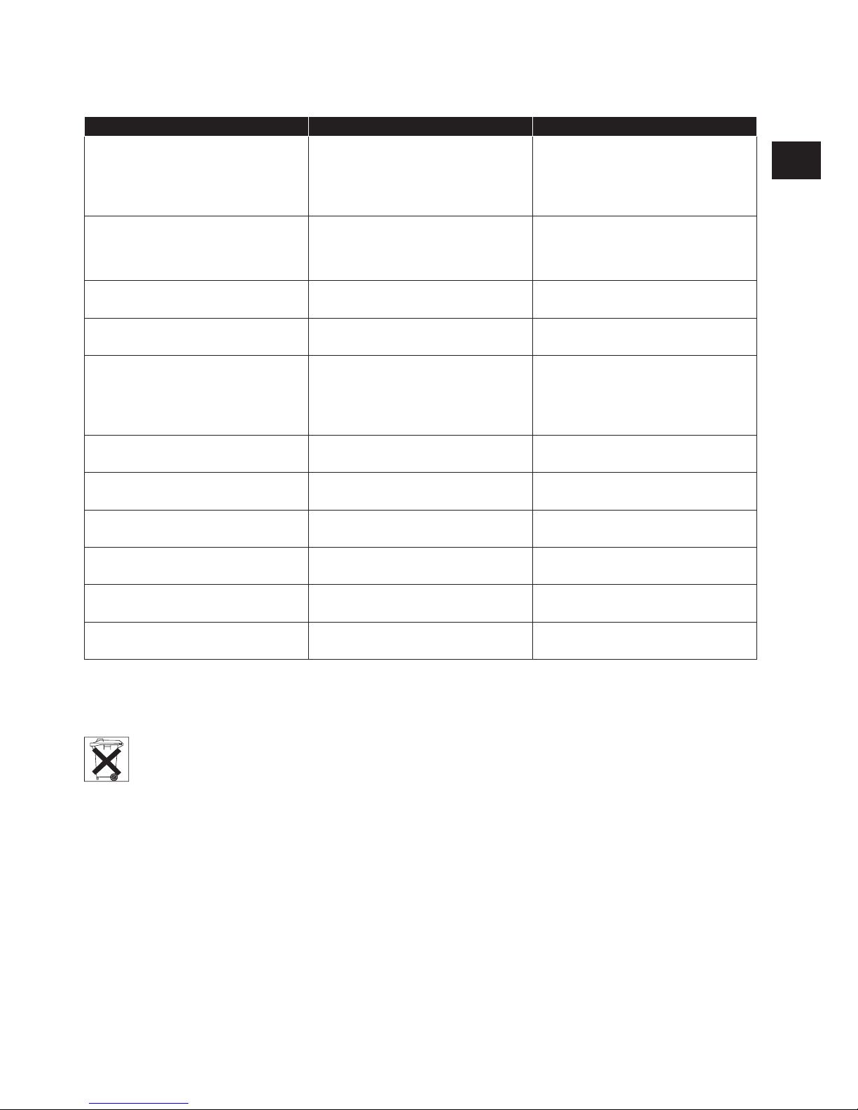
7 Malfunctions
MALFUNCTIONS
DESCRIPTION CAUSE ACTION
Attachment unit does not work Staple sensor does not register any
staples.
Check if the sensor works properly
by placing a staple bar on the loading
plate. The red light of the sensor must
now switch on, and switch off again
when you remove the bar.
Staples stuck in staple compartment. Pressure in the loading cylinder is ei-
ther too high or too low. The pressure
can be adjusted by the Senco service
engineer.
Staple stuck in guide body. Open the nozzle and remove the
staples.
No or insufcient compressed air. Check the compressed air (7-8 bar)
Material sensor does not register any
material.
This can be checked by detaching the
hose from the remote control. If air
escapes from the hose during operation of the tacker the tacker needs to
be repaired.
Compartment empty Fill the compartment
Control unit does not work Contact the supplier
Attachment unit stalls during moving Stapling is too deep. Increase distance between guide body
and material.
Stapling depth is uneven Insufcient supply of compressed air The pressure at the Smart Load
needs to be stable
Compressed air pressure too low The pressure is 7-8bar.
Material is too hard or its structure is
too uneven
8 Disposing of the Smart Load
When the system is scrapped, the regulations for waste disposal in force at the location and time of scrapping
must be observed. The system is constructed only of generally known materials. At the time of construction,
there were possibilities for waste processing and there were no known special risks for people responsible
for scrapping. The attachment unit and tools must be handed in to a sustainable recycling company (see
European Parliament and Council Directive 2012/19/ EU)
9 Technical data
Dimensions
Length: 444 mm
Width: 123 mm
Height: 280 mm
Weight: 10 kg.
Noise: >100 dB(A)
TECHNICAL DATA
Pneumatic
Compressed air: 6-8 bar
Consumption: 2,5 litres/ tacking
Load capacity: Vertical compartment for 21 staple bars
Operation: 24 Volts DC
8
GB
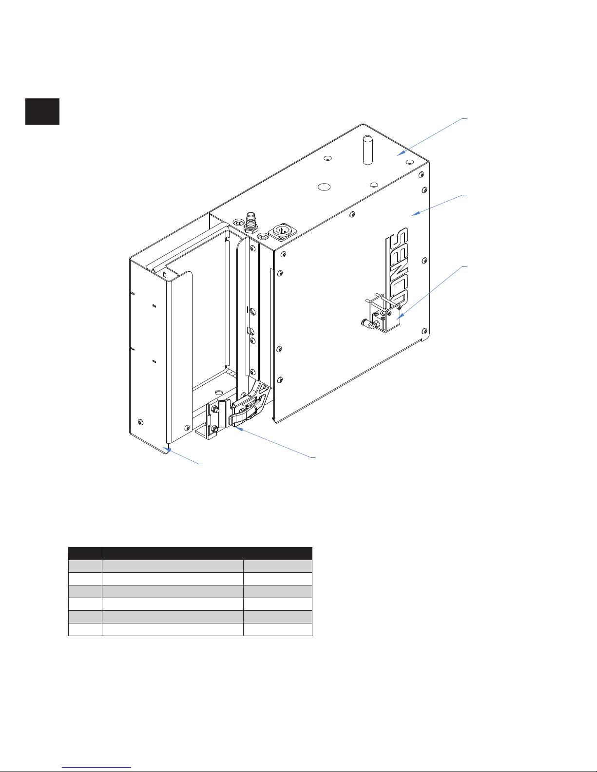
10.1 Smart Load assemby
PARTS OF SMART LOAD
10 Parts of Smart Load
Position Description Order number
A Tacker with upper- and vertical plate VSP-00319
B Site cover VSP-00212
C Remote control SHS51XP VSP-00239
D Changing magazine SHS51XP VSP-00228
E Steel-housing and staple transport VSP-00320
F Bolts VSP-00247
A
B
C
D
E

9
GB
1
2
10.2 Smart Load housing site
Position Description Order number
1 Site housing VSP-00212
2 Bolts VSP-00247
 Loading...